

Page 1
ENGLISH
ENGLISH
Operator’s Manual
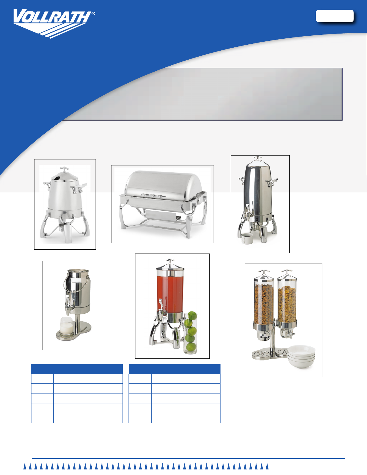
SOMERVILLE BUFFET SERVICE
Item Description
4634010 9 qt. Full-size Roll Top Chaffer
4635710 7 qt. Soup Urn
4635410 4 qt. Gravy Urn
4635310 3 gallon Coffee Urn
4635510 5 gallon Coffee Urn
Thank you for purchasing this Vollrath equipment. Before operating the equipment, read and familiarize yourself with the following operating and
safety instructions. SAVE THESE INSTRUCTIONS FOR FUTURE REFERENCE. Save the original box and packaging. Use this packaging to
ship the equipment if repairs are needed.
Item Description
4635110 Milk Dispenser
4635810 Juice/Cold Beverage Dispenser
4635210 Double Cereal Dispenser
4634110 6 qt. Round Drop-In Chafer
4635610 6 qt. Round Roll Top Chafer
Item No. 2350039-1 en Rev 02/12
Page 2
Buffet and taBletop Service
Safety PrecautionS
To ensure safe operation, read the following statements and
understand their meaning. This manual contains safety precautions
which are explained below. Please read carefully.
WARNING
Warning is used to indicate the presence of a hazard that can cause
severe personal injury, death, or substantial property damage if the
warning is ignored.
CAUTION
Caution is used to indicate the presence of a hazard that will or can
cause minor personal injury or property damage if the caution is
ignored.
NOTE
Note is used to notify people of installation, operation, or maintenance
information that is important but not hazard-related.
For Your Safety!
These precautions should be followed at all times. Failure to follow
these precautions could result in injury to yourself and others or
damage the equipment.
To reduce risk of injury or damage to the unit:
Equipment should only be used in a at, level position.
Do not store or place any materials below the unit or near the heating
source.
Always turn off and unplug electric chafer heaters when not in use.
Always use a snuffer paddle or saucer to extinguish ame when using a
chafer fuel heating source.
Allow equipment to cool before moving or cleaning.
Do not operate unattended.
Do not operate without water in the water pan body.
WARNING
Burn Hazard.
Do not touch heating surfaces, liquid, or while unit
is heating or operating.
and liquids can burn skin. Use gloves, mitts or
pot holders if it is necessary to handle hot pans,
plates and equipment.
Hot food, surfaces, steam
WARNING
Fire Hazard.
Use only chafer fuel designed for chafer use.
Do not install chafer fuel near combustible material.
Fire could occur.
WARNING
Electrical Shock Hazard.
Keep water and other liquids from entering the
inside of the heater. Liquid inside the heater could
cause an electrical shock. Do not damaged power
cord.
A
C
D
H
B
C
function and PurPoSe
This equipment is intended and designed to keep food at proper serving
temperatures. This equipment is not intended or designed to cook raw food or
to reheat prepared food. This equipment is not intended or designed to chill
beverages or food. Food and beverages must be prepared and placed into the
chafers, urns or dispensers at proper serving temperatures.
unPacking the equiPment and initial SetuP, all modelS
Carefully remove crating or packaging materials from the unit. When no longer
needed, dispose of all packaging materials in an environmentally responsible
manner. Follow any special instructions for specic models.
oPeration, tabletoP hot food and beverage
This equipment is designed to heat with an electric chafer heater or chafer fuel
designed specically for chafer application.
If using an electric chafer heater, we recommend that a Vollrath Universal
Chafer Heater is used.
If using fuel, use only high quality chafer gel fuel. Always follow the
manufacture’s recommendations for safety and usage.
2
OperatOr’s Manual
F
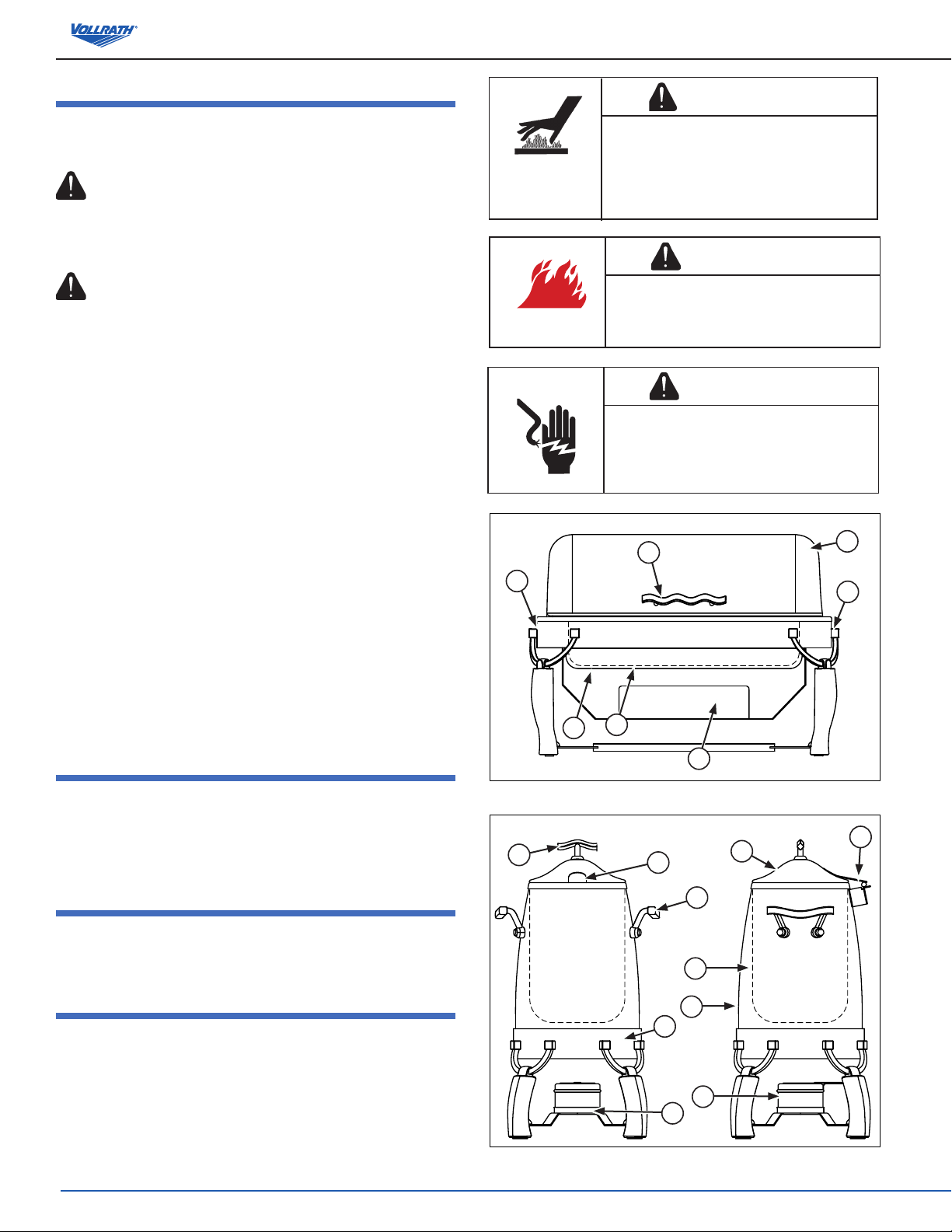
Figure 1. Chafer Features and Controls.
A
L
I
K
F
B
J
E
G
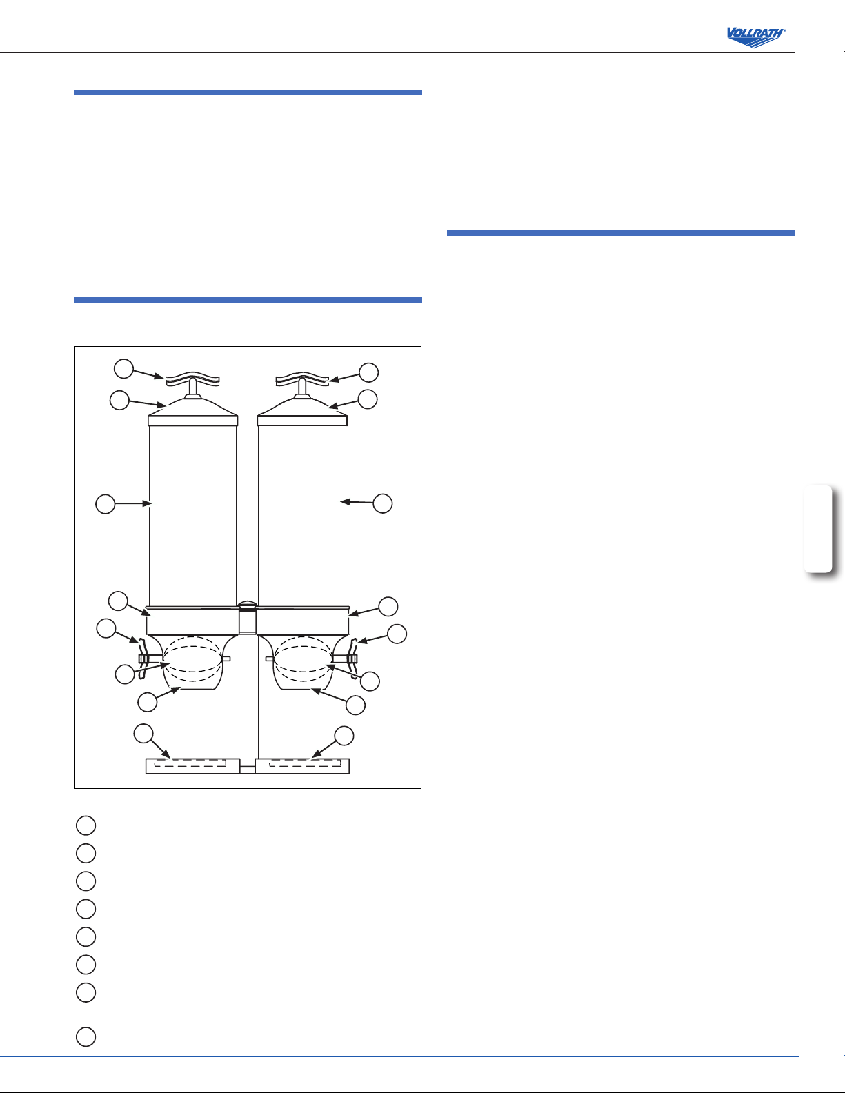
Figure 2. Soup Urn or Gravy Urn Features and Controls.
C
Page 3
A
O
N
K
F
B
J
M
G
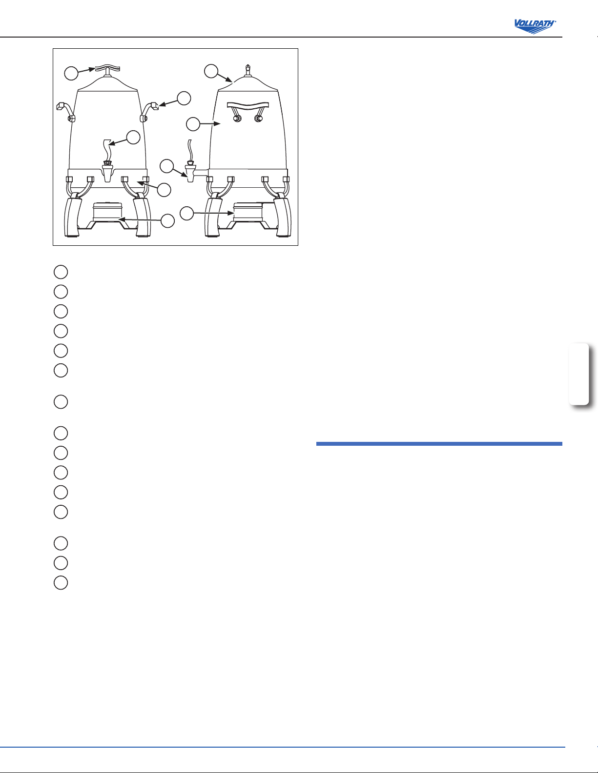
Figure 3. Coffee Urn Features and Controls.
A
COVER HANDLE. Used to open and close the cover.
B
COVER. Covers the food/beverage product.
C
HINGE. Allows the cover to rotate.
D
FOOD PAN. Holds the food product.
E
INSERT. Holds the food product.
F
HEATER/FUEL TRAY. Holds the electric chafer heater or
chafer fuel.
G
FUEL HOLDER with COVER. Designed to hold chafer fuel.
Includes a paddle for extinguishing the fuel ame.
H
WATER PAN. Holds the water.
I
URN BODY. Holds the water.
J
HANDLE. Used to lift the urn body.
K
BASE. Supports the urn body or beverage body.
L
UTENSIL CUTOUT. Opening that allows the handle of a
serving utensil remain in the insert with the cover closed.
M
BEVERAGE BODY. Holds the beverage product.
N
FAUCET. Opening that the beverage ows through.
O
FAUCET HANDLE. Controls the ow of beverage.
Buffet and taBletop Service
1. Remove the food pan (D) from the water pan (H) or remove the insert (E)
from the urn body (I). See Figures 1 and 2.
2. Pour about 2 quarts (2 L) of clean fresh water into the water pan (H) or
urn body (I).
NOTE:
Follow the manufacture’s instructions for usage and safety for the
electric chafer heater of chafer fuel.
3. Put the cover (B) in the closed position. Preheat the water by using a
universal electric chafer heater on “HI” or by using chafer fuel for 30
minutes.
4. Open the cover (B).
5. Place the food pan (D) or insert (E) containing food product that is
already at proper serving temperatures into the water pan (H) or urn
body (I). Close the cover (B).
NOTE:
Monitor food temperature closely for food safety. The United States
Public Health Service recommends that hot food be held at a minimum
of 140 ºF (60 ºC) to help prevent bacteria growth.
6. Regularly check the food temperature.
7. If necessary adjust the electric chafer heater between “HI” and “LO” to
maintain correct food temperature.
8. When nished with the equipment turn the electric chafer heater to the
“OFF” position and unplug or extinguish the ame on the chafer fuel
source.
ENGLISH
9. Open the cover (B). Remove the food pan (D) or the insert (E). When
removing hot food containers from unit use gloves, mitts or pot holders to
protect hands. See Figures 1 and 2.
10. Allow ample time for the water to cool. Remove the water pan (H) or the
urn body (I) and dispose of water.
cleaning, tabletoP hot food and beverage
To maintain the appearance and increase the service life, clean your
equipment daily.
1. Unplug the electric chafer heater or extinguish the ame on chafer fuel
and let it completely cool.
2. Remove the heating source.
3. Wipe the unit exterior with a clean damp cloth.
4. For coffee urns: Thoroughly clean the inside of the beverage body (E)
with hot water and mild soap. Run the hot soapy water through the faucet
(H). Rinse the beverage body (E) and faucet (H) completely with warm
water. Dry the equipment thoroughly.
5. Do not use abrasive materials, scratching cleansers or scouring pad to
clean the unit. These can damage the nish.
6. Thoroughly wipe off any mild soap or chemical cleaners. Residue could
corrode the surface of the unit.
OperatOr’s Manual
3
Page 4
Buffet and taBletop Service
oPeration, cold beverage diSPenSerS
This equipment is designed to help keep beverages chilled and at proper
1. Remove the cover (A) and ice tube(D). See Figure 4 and 5.
2. Place the pre-chilled beverage product into the beverage body (E). Leave
serving temperature.
3. Fill the ice tube (D) with ice and place into the beverage body (E).
B
I
D
E
NOTE:
Monitor food temperature closely for food safety. The United States
Public Health Service recommends that cold food/beverage be held at a
maximum of 41 ºF (5 ºC) to help prevent bacteria growth.
4. Regularly check the beverage temperature.
5. Remove the drip cover (G) from time to time and clean any spilled
I
H
6. When nished using the equipment remove cover (B). Remove and drain
7. Remove and empty the beverage body (E).
F
G
cleaning, cold and beverage
To maintain the appearance and increase the service life, clean your
equipment daily.
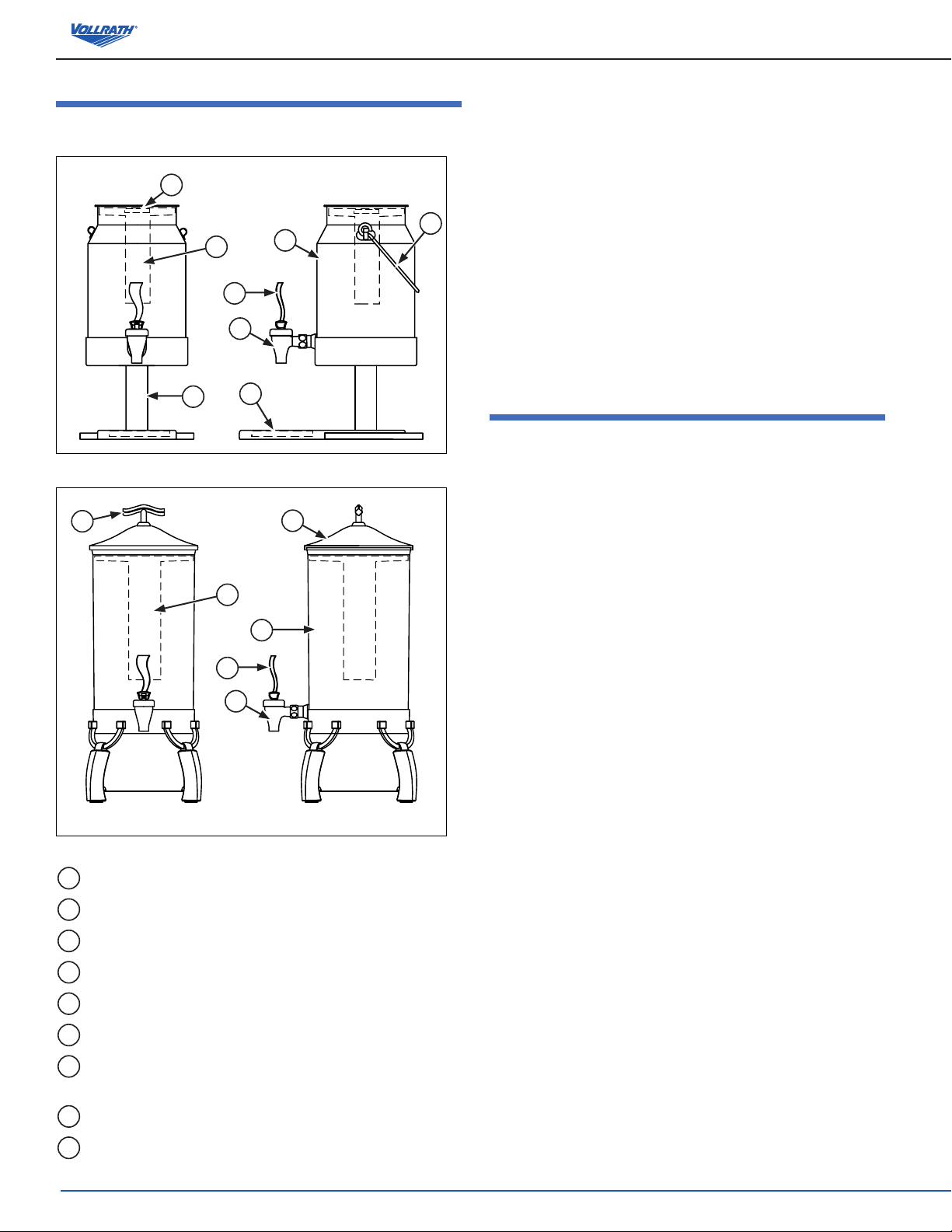
Figure 4. Milk Dispenser Features and Controls.
NOTE:
Do not use ammonia based cleaners on acrylic or plastics. Do not use
abrasive materials, scratching cleansers or scouring pad to clean the
A
B
unit. These can damage the nish.
1. Wipe the unit exterior with a clean damp cloth.
2. Thoroughly clean the inside of the beverage body (E) with hot water and
D
E
3. Thoroughly wipe off any mild soap or chemical cleaners. Residue could
I
room for the ice tube (D).
beverage.
the ice tube (D).
mild soap. Run the hot soapy water through the faucet (H). Rinse the
beverage body (E) and faucet (H) completely with warm water. Dry the
equipment thoroughly.
corrode the surface of the unit.
H
Figure 5. Juice and Beverage Features and Controls.
A
COVER HANDLE. Used to open and close the cover.
B
COVER. Covers the food/beverage product or ice tube.
C
HANDLE. For lifting or carrying the milk beverage body.
D
ICE TUBE. Holds ice to keep the beverage products cold.
E
BEVERAGE BODY. Holds the beverage product.
F
BASE. Supports the beverage dispenser.
G
DRIP COVER. Covers the drip trough on the base. Can be
removed for cleaning.
H
FAUCET. Opening that the beverage ows through.
I
FAUCET HANDLE. Controls the ow of beverage.
4
OperatOr’s Manual
Page 5
Buffet and taBletop Service
SetuP, cereal diSPenSer
Carefully remove crating or packaging materials from the unit. When no
longer needed, dispose of all packaging materials in an environmentally
responsible manner.
1. Set the food chute (F) into the base (D). See Figure 7. The food chute (F)
is wider at the bottom. It ts onto the base (D) one way.
2. Set the paddle (H) into the food shoot (F) and align the holes.
3. Push the dispensing handle (E) through the holes of the paddle (H) and
food chute (F).
4. Set the food tube (C) onto the base (D) and set the cover (B) into place.
oPeration, cereal diSPenSer
This equipment is designed to dispense cereal type food product. A variety of
food products may be used with this dispenser.
1. Remove the cover (B) and place the food product into the food tube (C)
and return the cover (B). See Figure 7.
2. Place a bowl or other container under the food chute (F).
3. Rotate the dispensing handle (E) until the desired amount of food
product has been dispensed.
4. Remove the drip cover (G) from time to time and clean any spilled food
product.
cleaning, cereal diSPenSer
To maintain the appearance and increase the service life, clean your
equipment daily.
NOTE:
Do not use ammonia based cleaners on acrylic or plastics. Do not use
abrasive materials, scratching cleansers or scouring pad to clean the
unit. These can damage the nish.
1. Slide the dispensing handle (E) out of the food chute (F) and paddle. See
A
B
A
B
Figure 7.
2. Lift the food tube (C), food chute (F) and cover (B) out of the base (D).
3. Remove the cover (B). Store or discard the food product following local
food handling and storage codes. Retain the paddle (H) for reuse.
4. Thoroughly wash the components with hot soapy water and a soft cloth.
Wipe the unit exterior with a clean damp cloth.
C
D
E
H
F
G
F
G
Figure 7. Cereal Dispenser Features and Controls.
A
COVER HANDLE. Used to open and close the cover.
B
COVER. Covers the food/beverage product.
C
FOOD TUBE. Holds the food product.
D
BASE. Holds food tube and dispensing mechanism.
E
DISPENSING HANDLE. Dispenses food product when rotated.
F
FOOD CHUTE. Area where the food product is dispensed.
G
DRIP COVER. Covers the drip trough on the base. Can be
removed for cleaning.
H
PADDLE. Controls the ow of food product.
ENGLISH
C
D
E
H
OperatOr’s Manual
5
Page 6

Buffet and taBletop Service
initial SetuP, droP-in chafer
Carefully remove crating or packaging materials from the unit. When no longer
needed, dispose of all packaging materials in an environmentally responsible
manner.
For new installations:
Cutout dimensions are for reference only. Vollrath recommends that actual
cutouts be made when the chafer is received. Small variances in chafer
dimensions can happen and it is best to mate the chafer with the counter-top
before cutting.
1. Cut out counter opening using chafer and Figure 6.
19” (48.25 cm)
Figure 6. Cutout Dimensions.
2. Remove the food and water pan from the chafer.
3. Remove two (2) nuts from beneath spacer on underside rim of chafer.
4. Gently place chafer into the opening.
5. Decide which mounting clips are appropriate for your application (short clips
for thin counters and long clips for thicker counters).
6. Using the hole that is already threaded start threading the thumbscrew
into the clip approximately 1/2”. Do not thread too far or you may not have
enough room to insert the clip under the chafer in the next step.
7. From below, slide the clips over the studs where you removed the two nuts
in step 3, so that the clip hangs down and points out from the chafer rim.
Reattach nuts to the studs and tighten. Finish threading thumbscrews to
tighten the chafer to the bottom side of the counter. This will work with either
composite or stainless steel countertops.
8. Attach the heater tray assembly to the inside band of the chafer. Remove
Phillips head screw from each side of band by hinge. Attach tray bracket so
the tray is under the counter with the tray facing. Reattach screws.
9. Follow the steps in the OPERATION, DROP-IN CHAFER Section of this
manual.
For Retrot Installations:
NOTE:
Always size the hole and make sure it meets min/max cut out
dimensions below. Always receive the chafer and retrot kits prior
to cutting any countertops. Due to changes in manufacturer’s
specications, and to different installation requirements, Vollrath’s
retrot kits will t a majority of installations. Extreme care must be made
to measure cut out holes prior to ordering and installation.
Identify the model that you are replacing and measure the opening.
Round Adaptor Ring: Part# 46281 - Sized to replace Many round chafers of
approximately 6 quart capacities.
Minimum Cutout Dimension: 18 5/8” diameter.
Maximum Cutout Dimension: 19-1/2” diameter.
NOTE:
6 qt. Chafers are far less standardized in size than rectangle chafers.
Measure everything carefully and conrm measurements with actual
chafer before making nal cut.
10. Place adaptor ring over opening. Remove cover, food and water pans
from chafer and then place the chafer body into the adapter opening and
center both over the existing opening in the counter top.
11. Remove the two (2) nuts from beneath spacer on rim of chafer.
12. Decide which mounting clips are appropriate for your application (short
clips for thin counters and long clips for thicker counters).
13. Using the hole that is already threaded start threading the thumbscrew
into the clip approximately 1/2”. Do not thread too far or you may not have
enough room to insert the clip under the chafer in the next step.
14. From below, slide the clips over the studs where you removed the two
nuts in step 3, so that the clip hangs down and points out from the chafer
rim. Reattach nuts to the studs and tighten. Finish threading thumbscrews
to tighten the chafer to the bottom side of the counter. This will work with
either composite or stainless steel countertops.
15. Follow the steps in the OPERATION, DROP-IN CHAFER Section of this
manual.
6
OperatOr’s Manual
Page 7

Buffet and taBletop Service
oPeration, droP-in chafer
This equipment is designed to heat with an electric chafer heater only.
WARNING
Burn Hazard.
Do not touch heating surfaces, liquid, or while unit
is heating or operating.
and liquids can burn skin. Use gloves, mitts or
pot holders if it is necessary to handle hot pans,
plates and equipment.
Hot food, surfaces, steam
WARNING
Electrical Shock Hazard.
Keep water and other liquids from entering the
inside of the heater. Liquid inside the heater could
cause an electrical shock. Do not damaged power
cord.
A
C
B
C
1. Remove the food pan (D) from the water pan (E) ). See Figures 7.
2. Pour about 2 quarts (2 L) of clean fresh water into the water pan (E).
NOTE:
Follow the manufacture’s instructions for usage and safety for the
electric chafer heater.
3. Put the cover (B) in the closed position. Preheat the water by using a
universal electric chafer heater on “HI” for 30 minutes.
4. Open the cover (B).
5. Place the food pan (D) containing food product that is already at proper
serving temperatures into the water pan (E). Close the cover (B).
NOTE:
Monitor food temperature closely for food safety. The United States
Public Health Service recommends that hot food be held at a minimum
of 140 ºF (60 ºC) to help prevent bacteria growth.
6. Regularly check the food temperature.
7. If necessary adjust the electric chafer heater between “HI” and “LO” to
maintain correct food temperature.
8. When nished with the equipment turn the electric chafer heater to the
“OFF” position and unplug.
9. Open the cover (B). Remove the food pan (D). When removing hot food
containers from unit use gloves, mitts or pot holders to protect hands.
See Figures 6.
10. Allow ample time for the water to cool. Remove the water pan (E) and
ENGLISH
dispose of water.
E
D
F
Figure 7. Drop-In Chafer Features and Controls.
A
COVER HANDLE. Used to open and close the cover.
B
COVER. Covers the food/beverage product.
C
HINGE. Allows the cover to rotate.
D
FOOD PAN. Holds the food product.
E
WATER PAN. Holds the water.
F
HEATER/FUEL TRAY. Holds the electric chafer heater.
cleaning, tabletoP hot food and beverage
To maintain the appearance and increase the service life, clean your
equipment daily.
1. Unplug the electric chafer heater and let it completely cool.
2. Remove the heating source.
3. Wipe the unit exterior with a clean damp cloth.
4. Do not use abrasive materials, scratching cleansers or scouring pad to
clean the unit. These can damage the nish.
5. Thoroughly wipe off any mild soap or chemical cleaners. Residue could
corrode the surface of the unit.
OperatOr’s Manual
7
Page 8

Buffet and taBletop Service
SPare PartS liSt - and eXPloded vieW - model 4634010
1
5
7
66
66
66
2
4
63
13
8
10
11
6
610
610
12
13
66
5
9
13
610
8
13
6
8
Callout Part Number Description
1 4634020-1 Cover with Handle
2 N/A Handle
3 N/A Bolt, Hex Head
4 46259 Water Pan
5 K4634010-1 Hinge, Complete Assembly, Kit
6 N/A Bolt, Hex Head
7 N/A Outer Ring
8 N/A Power Cord Support
9 N/A Inner Ring
10 N/A Nut and Screw
OperatOr’s Manual
614
Callout Part Number Description
11 N/A Fuel Band and Tray
12 N/A Leg Frame
13 N/A Leg with Yoke
14 46864 Fuel Holder with Cover
N/A Rubber Feet (not shown)
Kit, includes 2 Legs with Yoke,
K4634010-2
K4634010-3
Leg Frame, Fuel Band and Tray,
and all necessary hardware.
Kit, includes Handle and bolts, 4
Rubber Feet, and all hardware.
Page 9

Buffet and taBletop Service
SPare PartS liSt - and eXPloded vieW - modelS 4635710 and 4635410
8
10
7
9
66
1
5
66
2
Callout Part Number Description
1 4635730-1 Soup Insert, 7 Quart
2 N/A Soup Body, 7 Quart
3 4635430-1 Gravy Insert, 4 Quart
4 N/A Gravy Body, 4 Quart
5 N/A Handle, Side
6 N/A Nuts, Special
7 4635720-1 Soup Cover with Handle
7 4635420-1 Gravy Cover with Handle
8 N/A Handle
9 N/A Stand Ring
10 N/A Leg with Yoke
11 46864 Fuel Holder with Cover
12 N/A Leg Frame
N/A Rubber Feet (not shown)
K4635710-1 Leg Kit, includes 2 Legs with Yokes, Leg Frame and all hardware
K4634020-1 Kit, includes 2 Side Handles, Special Nuts and 2 Rubber Feet.
3
11
10
12
4
5
66
10
10
ENGLISH
OperatOr’s Manual
9
Page 10

Buffet and taBletop Service
SPare PartS liSt - and eXPloded vieW - model 4635310 and 4635510
2
13
1
4
63
6
7
8
8
7
5
63
13
9
610
4
12
11
13
13
Callout Part Number Description
1 4635510-1 Cover with Handle
2 N/A Handle, Cover
3 N/A Bolt, Hex Head
4 N/A Handle, Urn
5 K4635510-1
6 K4635310-1
7 N/A Faucet Nut
8 K4635520-1
9 N/A Ring
10 N/A Nut and Screw
Coffee Urn, 5 gallon (includes
Faucet Kit, Handle and hardware)
Coffee Urn, 3 gallon (includes
Faucet Kit, Handle and hardware)
Faucet Assembly
(includes Faucet Nut)
Callout Part Number Description
11 46864 Fuel Holder with Cover
12 N/A Fuel Frame
13 N/A Leg with Yoke
N/A Rubber Feet (not shown)
Leg Kit, includes 2 Legs with Yoke,
K4635710-1
K4634020-1
Leg Frame, Fuel Band and Tray,
and all necessary hardware.
Kit, includes Handle and bolts, 4
Rubber Feet, and all hardware.
10
OperatOr’s Manual
Page 11

11
13
Buffet and taBletop Service
SPare PartS liSt - and eXPloded vieW - modelS 4635810 and 4635110
10
15
14
1
9
3
8
5
4
5
13
7
612
13
4
6
2
ENGLISH
13
Callout Part Number Description
1 4635110-1 Cover, Ice Tube
2 4635120-1 Ice Tube, Milk
3 K4635110-1
4 N/A Faucet Nut
5 K4635520-1 Faucet Kit (includes Faucet Nut)
6 4635130-1 Milk Base (includes Drip Cover)
7 4635210-1 Drip Cover
8 4635810-1
Body, Milk (includes Faucet Kit,
Handle and hardware)
Body, Juice (includes Faucet Kit,
Handle and Hardware)
Callout Part Number Description
9 4635820-1 Ice Tube, Juice
10 4635830-1 Cover, Juice (includes Handle)
11 N/A Handle
12 N/A Screws
13 N/A Leg with Yoke
14 N/A Cross Support
15 N/A Ring
15 4635840-1
Kit, includes 2 Legs with Yokes, Leg
Frame and all hardware
OperatOr’s Manual
11
Page 12

Buffet and taBletop Service
SPare PartS liSt - and eXPloded vieW - model 4635210
8
8
7
7
6
6
2
1
5
4
4
3
3
5
4
4
2
Callout Part Number Description
1 4635220-1 Base, Cereal (includes Cover)
2 4635210-1 Cover, Drip
3 K4635210-1 Handle, Dispensing Kit (includes Food Chute)
4 N/A Chute, Food
5 4635230-1 Paddle
6 4635240-1 Food Tube
7 4635250-1 Cover (includes Handle)
8 N/A Handle
12
OperatOr’s Manual
Page 13

Buffet and taBletop Service
SPare PartS liSt - and eXPloded vieW - model 4634110
5
1
63
5
2
4
8
69
69
7
6
ENGLISH
8
10
Callout Part Number Description
1 4634130-1 Cover with Handle
2 N/A Handle
3 N/A Bolt, Hex Head
4 4634100-1 Water Pan
5 4634120-1 Hinge, Complete Assembly, Kit
6 N/A Outer Ring
7 N/A Inner Ring
8 N/A Power Cord Support
9 N/A Nut and Screw
10 N/A Fuel Band and Tray
OperatOr’s Manual
13
Page 14

Buffet and taBletop Service
11
1
5
2
8
7
4
63
5
8
6666
7
610
10
12
6
13
6
13
13
SPare PartS liSt - and eXPloded vieW - model 4635610
14
Callout Part Number Description
1 4634130-1 Cover with Handle
2 N/A Handle
3 N/A Bolt, Hex Head
4 4634100-1 Water Pan
5 K4634010-1 Hinge, Complete Assembly, Kit
6 N/A Bolt, Hex Head
7 N/A Outer Ring
8 N/A Power Cord Support
OperatOr’s Manual
9 N/A Inner Ring
10 N/A Nut and Screw
11 N/A Fuel Band and Tray
12 N/A Leg Frame
13 N/A Leg with Yoke
N/A Rubber Feet (not shown)
Kit, includes 2 Legs with Yoke,
K4635610-1
Leg Frame, Fuel Band and Tray,
and all necessary hardware.
Page 15

Buffet and taBletop Service
Warranty Statement for the vollrath co. l.l.c.
The Vollrath Company LLC warrants the products it manufactures and distributes against defects in materials and workmanship for a period of one year, except as specically
provided below. The warranty runs 12 months from the date of original installation. (End user receipt)
1. Refrigeration compressors – The warranty period is 5 years.
2. Replacement parts – The warranty period is 90 days.
3. Fry pans and coated cookware – The warranty period is 90 days
4. EverTite™ Riveting System – The warranty covers loose rivets
only, forever.
5. Cayenne® Heat Strips – The warranty period is 1 year plus an
additional 1 year period on heating element parts only.
6. Ultra and Professional Induction Ranges – The warranty period
is 2 years.
7. Mirage and Commercial Induction ranges - The warranty period
is 1 year.
8. ServeWell® Induction Workstations – The warranty period is one
year on the workstation table and 2 years on induction hobs.
9. Slicers – The warranty period is 10 years on gears and 5 years
on belts.
10. Mixers – The warranty period is 2 years.
11. Extended warranties are available at the time of sale.
12. Boxer Mixers – 1 Year exchange Warranty.
13. Vollrath – Redco products – The warranty period is 2 years.
14. Optio / Arkadia product lines – The warranty period is 90 days.
15. All non-stick products (i.e. fry pans and surfaces) are 90 days for
the non stick surfaces.
All products in the Jacob’s Pride® collection, including
the following, have a lifetime warranty:
• NSF Certied One-Piece Dishers
• NSF Certied Spoodle® Utensils
• NSF Certied Heavy-Duty Spoons with
Ergonomic Handle
• NSF Certied Heavy-Duty Basting Spoons
• Heavy duty Turners with Ergonomic handle
• One-Piece Tongs*
• Heavy-Duty One-Piece Ladles*
• Nylon Handle Whips
Items sold having no warranty:
• Meat Grinder Knives
• Light Bulbs in Convection Ovens and Hot
• Oven Door Seals
• Oven Door Glass
• Hot Food Merchandisers / Display Case
• Calibration and set up of gas equipment
• Slicer / Dicer blades (table top food prep) –
• One-Piece Skimmers
• Tribute®, Intrigue®, and Classic Select®
Cookware*
*Jacob’s Pride® warranty does not cover KoolTouch®, non stick coatings and silicone handles.
Food Merchandiser
Glass
Redco and Vollrath
THIS WARRANTY IS IN LIEU OF ANY OTHER WARRANTIES, EXPRESS OR IMPLIED, INCLUDING ANY IMPLIED WARRANTY OF
MERCHANTABILITY OR FITNESS FOR A PARTICULAR PURPOSE
As The Vollrath Company LLC’s only responsibility and the purchaser’s only remedy, for any breach of warranty, The Vollrath Company LLC will repair or, at its option, replace the
defective product or part without charge, except as otherwise provided below:
ENGLISH
• For refrigeration compressors and the second year of the warranty on Cayenne® Heat Strips and mixers, The Vollrath Company LLC will provide the repaired
or replacement part only; and the buyer will be responsible for all labor charges incurred in performing the repair or replacement.
• To obtain warranty service, the buyer will be responsible to return to The Vollrath Company LLC any product (other than gas equipment that is permanently
installed) weighing less than 110 lbs. or located outside of a 50-mile radius of a certied technician designated by The Vollrath Company LLC to perform
warranty repairs. If a Vollrath Technician cannot be contacted check the website for service contact points. (Please refer to the Product Catalogue for weights
and sizes of product)
• No remedy will be available for products that have been damaged by accident, carelessness, improper installation, lack of proper setup or supervision when
required, neglect, improper use, installation or operation contrary to installation and operating instructions or other causes not arising out of defects in materials or workmanship. At the buyer’s request, The Vollrath Company LLC will repair and or replace such products at a reasonable cost.
• No remedy will be available for slicers where blade has not been sharpened (Refer to owner’s manual for sharpening instructions)
• No remedy will be available for mixers damaged by changing gears while unit is running or overloading, in either case as determined by a Vollrath Certied
Technician
• Warranty work must be authorized in advance by The Vollrath Company LLC. See the operating and safety instructions for each product for detailed warranty claim procedures.
• No remedy will be available for product returned and found to be acceptable to the product specication.
• No remedy will be available under any warranty not registered as required below.
LIMITATION OF LIABILITY:
THE VOLLRATH COMPANY LLC SHALL HAVE NO LIABILITY FOR INCIDENTAL OR CONSEQUENTIAL DAMAGES OF ANY KIND,
WHETHER BASED UPON NEGLIGENCE OR OTHER TORT, BREACH OF WARRANTY, OR ANY OTHER THEORY.
OperatOr’s Manual
15
Page 16

Warranty Procedure
On all warranty calls, the following process and information is required:
• All warranty claims will start with a call to Vollrath Technical Service support line (800-628-0832).
• A technical support professional will work to diagnose the issues, and provide the details for the service solution.
• Name and phone number of person calling
• Business name, street address, city, state and zip
• Model and serial number
• Date of purchase and proof of purchase (Receipt)
• Name of dealer where unit was purchased
NOTE: Vollrath will not accept products sent without the proper procedure being followed.
Important:
TO MAKE A CLAIM FOR ANY REMEDY UNDER THIS WARRANTY, YOU MUST REGISTER YOUR WARRANTY.
regiSter today
ONLINE: Register your warranty on-line now at www.Vollrathco.com
NO WEB ACCESS: If you do not have access to the web, kindly register by completing the warranty registration form and faxing it to The Vollrath Co. LLC ofce in the country of
purchase.
Product regiStration
buSineSS name
key contact name email
Street addreSS
city State ZiP code
country Phone faX
model item number
Serial number
- -
oPeration tyPe
R Limited Service Restaurant R Full Service Restaurant R Bars and Taverns R Supermarket
R Convenience Store R Recreation R Hotel/Lodging R Airlines
R Business/Industry R Primary/Secondary School R Colleges/University R Hospitals
R Long-Term Care R Senior Living R Military R Corrections
reaSon for Selecting our Product
R Appearance R Full Service Restaurant R Availability R Sellers Recommendation
R Ease of Operation R Versatility of Use R Price R Brand
Would you like to receive our full-line catalog and remain on our mailing liSt? R Yes R No
www.vollrathco.com
The Vollrath Company, L.L.C.
1236 North 18th Street
Sheboygan, WI 53081-3201
U.S.A.
Main Tel: 920.457.4851
Fax: 800.752.5620
Technical Services: 800.628.0832
Service Fax: 920.459.5462
Canada Service: 800.695.8560
© 2013 The Vollrath Company, L.L.C.
 Loading...