

Page 1
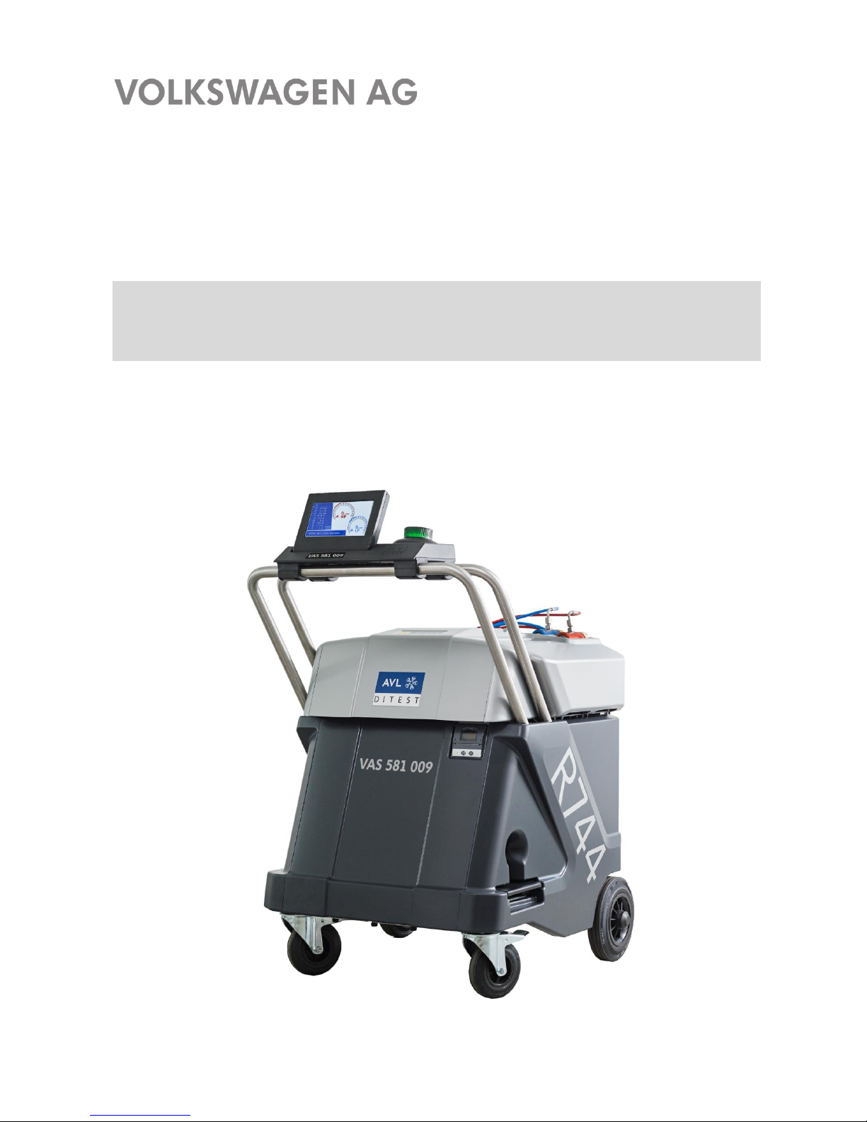
VAS 581 009
Unpacking instructions
Placing into service instructions
Quick start guide
V2.00 05/18
Please read carefully!
Page 2

Contents
VAS 581 009 unpacking instructions, placing into service, quick start guide
V2.00 05/18 All rights reserved.
1
Contents
SAFETY INSTRUCTIONS ............................................................................... 2
SAFETY INSTRUCTIONS FOR CARBON DIOXIDE CO2 (R744) .................. 4
SAFETY INSTRUCTIONS FOR NITROGEN N2 .............................................. 5
OTHER SAFETY INSTRUCTIONS ................................................................. 5
OPERATING AND AUXILIARY MATERIALS ................................................. 5
1 IMPORTANT INFORMATION .................................................................. 6
2 UNPACKING INSTRUCTIONS ................................................................ 7
3 SCOPE OF DELIVERY ............................................................................ 9
4 PLACING INTO SERVICE ..................................................................... 10
4.1 Installation location / stability .................................................................................... 10
4.2 Checking the vacuum pump oil ................................................................................. 11
4.3 Power connection ..................................................................................................... 11
4.4 Switching on the VAS 581 009 ................................................................................. 12
4.5 Pressure zeroing ....................................................................................................... 17
4.6 Oil/UV additive scales zeroing .................................................................................. 18
4.7 Connecting the refrigerating agent cylinder CO2 (R744) .......................................... 19
5 AVAILABLE ACCESSORIES ................................................................ 31
6 QUICK START GUIDE ........................................................................... 32
7 FAULT CONDITIONS ............................................................................ 34
We reserve the right to make changes to the form, equipment and technology of the delivery.
Therefore, no rights can be derived from the specifications, figures and descriptions in these
instructions. Reprinting, reproduction or translation for third parties, in part or in whole, are
not permitted without the written permission of Volkswagen AG/the manufacturer.
Volkswagen AG / the manufacturer expressly reserves all rights under the German
Copyright Act. Subject change.
VOLKSWAGEN AG Publisher: AVL DiTEST GmbH
KD-Werkstattausrüstung Alte Poststraße 156
D-38436 Wolfsburg 8020 Graz
AUSTRIA
VAS 581 009 AVL DiTEST ID No. AT7912EN Rev. 02
ASE 581 009 00 000
Page 3
Safety instructions
VAS 581 009 unpacking instructions, placing into service, quick start guide
V2.00 05/18 All rights reserved.
2
SAFETY INSTRUCTIONS
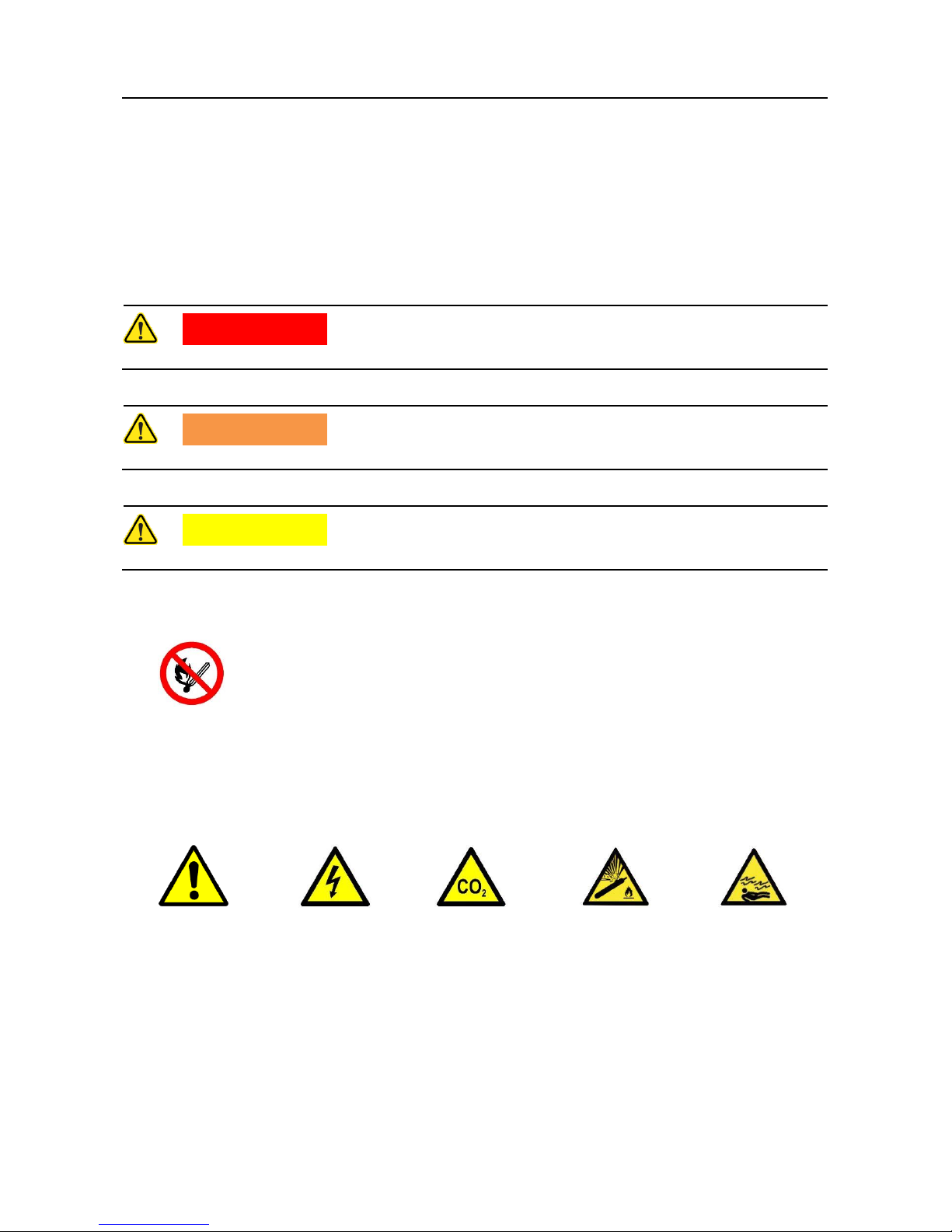
Sign and symbols
Symbols with the following meanings are used in the safety instructions of the operating
instructions, unpacking instructions, placing into service instructions, quick start guide or
other supplied instructions as well as on the display of the tester during operation and on
the products themselves:
DANGER
Indicates an extreme danger that can lead to death if not avoided.
WARNING
Indicates an imminent danger that can lead to death or severe injury if not avoided.
CAUTION
Indicates a danger that can lead to moderate or minor injuries.
Prohibition signs
Fire and open
flames
prohibited
Warning signs
General
Risk of electric
shock
Hazardous
gases
Warning of gas
cylinders
Danger of
suffocation
Page 4
Safety instructions
VAS 581 009 unpacking instructions, placing into service, quick start guide
V2.00 05/18 All rights reserved.
3
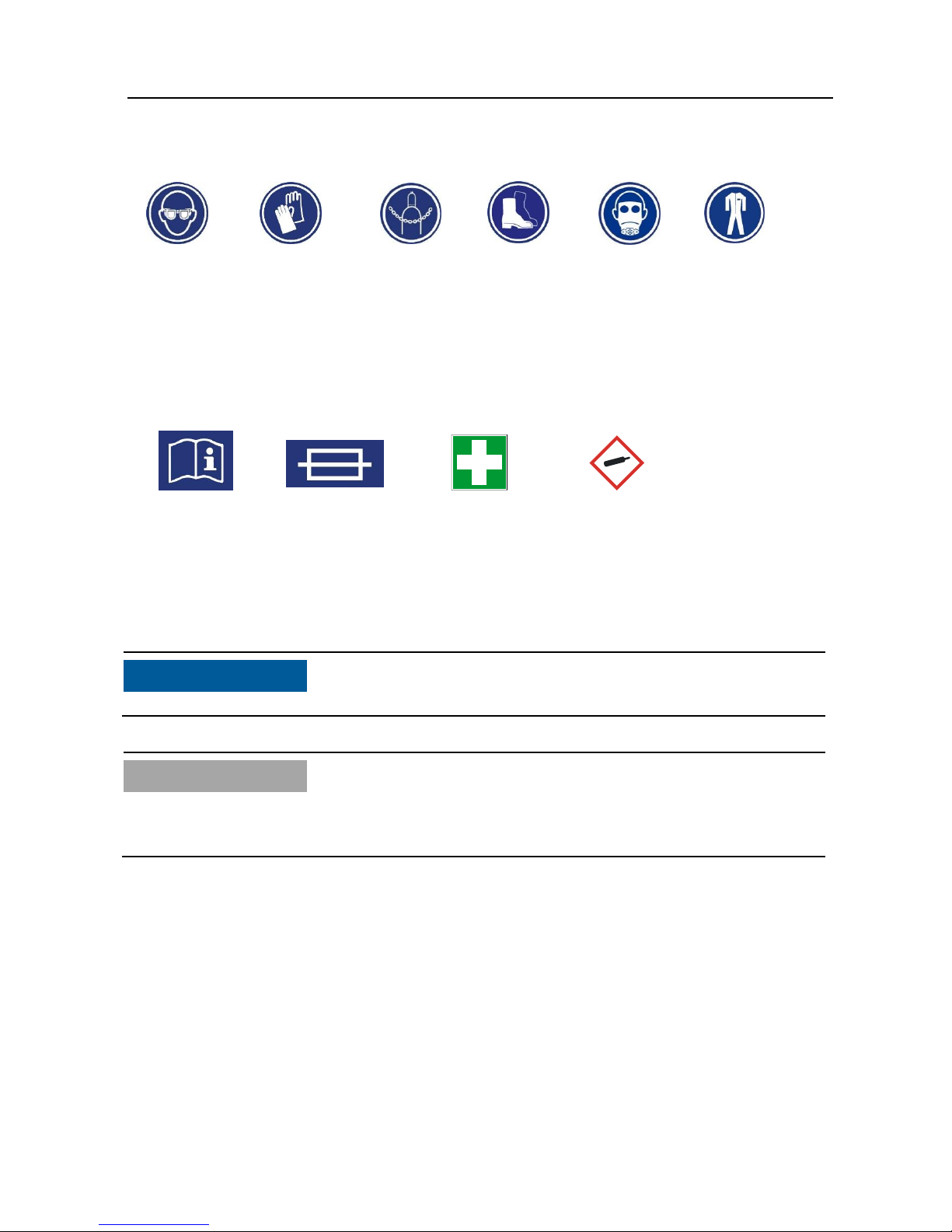
Mandatory signs
Wear
protective
goggles
Wear gloves
Refrigeratin
g agent
cylinder
Secure CO2
(R744)
Wear
protective
shoes
Wear
respiratory
protection
Wear
protective
clothing
Other symbols
Observe
operating
instructions
Fuse
First aid
Gas cylinder
Notices
NOTICE
This text points to situations or mal operations that can lead to damage or data loss.
Information
This text indicates important information or instructions.
Failure to comply with these instructions will prevent or significantly hinder the successful
implementation of the actions described in this documentation.
Page 5
Safety instructions
VAS 581 009 unpacking instructions, placing into service, quick start guide
V2.00 05/18 All rights reserved.
4
SAFETY INSTRUCTIONS FOR CARBON DIOXIDE CO
2
(R744)
Always observe the manufacturer's safety data sheet!
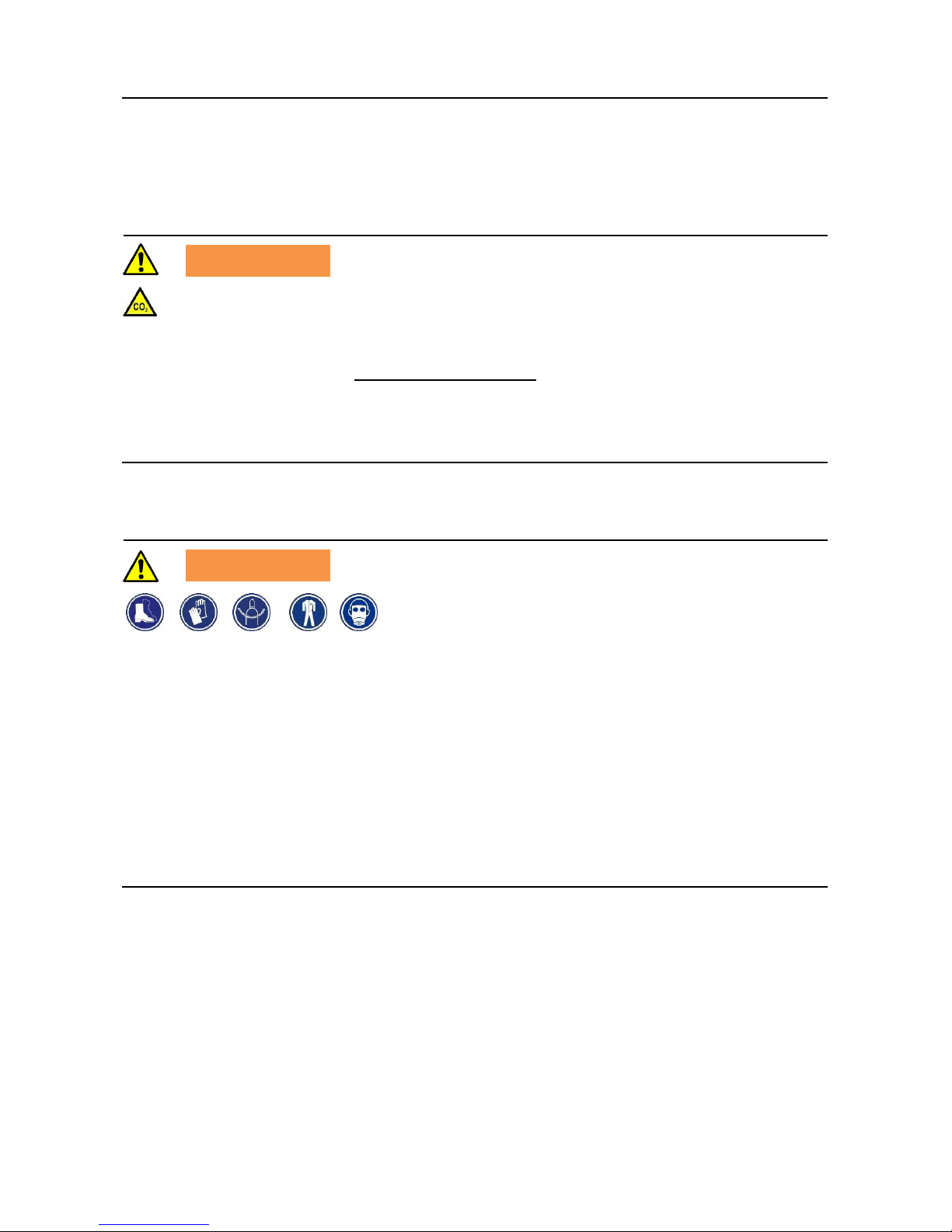
WARNING
Contact with the product can cause cold burns or frostbite.
Gases/vapours are heavier than air. High concentration due to accumulation in closed
rooms, work pits, cellars, etc. can cause asphyxiation, among other things. Symptoms:
Loss of motor ability and consciousness. Affected persons do not realise that they are
suffocating.
Do not allow carbon monoxide to enter sewage systems, pits or similar enclosures where
gas accumulation may be dangerous.
Precautions and behaviour rules
WARNING
Storage: Store container in a well-ventilated place at a temperature below 50 °C.
Protect container against impacts and falls (secure with chain).
Handling: Avoid contact with eyes and skin. Do not inhale the gas. Ensure that no water
enters the gas cylinder/container.
Prevent the gas from flowing back into the gas tank. Only use equipment that is suitable
for this product and the intended pressure and temperature. Check fittings, connections
and lines for leaks. Eating, drinking and storing food in the working area are prohibited.
Respiratory protection: Self-contained breathing apparatus.
Eye protection: Tightly fitting protective goggles.
Hand protection: Protective gloves (material: leather).
Body protection: Protective clothing.
Page 6

Safety instructions
VAS 581 009 unpacking instructions, placing into service, quick start guide
V2.00 05/18 All rights reserved.
5
Behaviour in the event of danger
After a gas leak: Keep unprotected persons away. Ventilate rooms well. Wear protective
gear and self-contained breathing apparatus. Close valves / stop gas leak. Avoid entry into
cellars, pits and similar enclosures (danger of suffocation).
In case of fire: Wear protective gear and self-contained breathing apparatus. Stop gas
leak if possible. Cool cylinders with a water jet from a secure position and remove them
from the fire zone if possible to prevent explosion! The product itself is non-flammable.
Extinguishing agents: All known extinguishing agents can be used.
Escape routes: Escape routes must be known to staff.
Accident phone: The accident phone must be known to staff.
First aid
Please observe the instructions for use and safety of your refrigerant supplier..
SAFETY INSTRUCTIONS FOR NITROGEN N
2
Always observe the manufacturer's safety data sheet!
For safety instructions, please refer to the operating instructions.
OTHER SAFETY INSTRUCTIONS
For safety instructions, please refer to the operating instructions.
OPERATING AND AUXILIARY MATERIALS
Before using operating and auxiliary materials, the material safety data sheets for the
product and the manufacturer's instructions must be read.
An appropriate safety concept must be developed and adhered to based on these material
safety data sheets.
KEEP THESE INSTRUCTIONS IN A SAFE PLACE!
Page 7

Important information
VAS 581 009 unpacking instructions, placing into service, quick start guide
V2.00 05/18 All rights reserved.
6
1 Important information
Dear Customer,
Please observe the following points in case of transport damage/incomplete delivery.
External damage to goods/packaging (without/with outer packaging):
Describe the damage (condition of the goods/packaging)
Include photos whenever possible (before and after unloading)
Write down the damage on the freight documents and have the driver sign.
Contact Volkswagen, K-VO-W department as soon as possible.
No external damage to goods/packaging / subsequently discovered defects /
missing parts:
Describe the damage
Include photos if possible
Check the delivery; see unpacking instructions, placing into service instructions,
Sec. 2 "Scope of delivery"
Please contact
AVL DiTEST Fax +49 9103 7131-112 immediately
Warranty
The warranty period is 12 months starting from the day of registration / activation of the
device.
Please use the information provided on the device to register/activate and place the device
into service.
For further information, please contact:
AVL DiTEST Deutschland
Page 8
Unpacking instructions
VAS 581 009 unpacking instructions, placing into service, quick start guide
V2.00 05/18 All rights reserved.
7
2 Unpacking instructions
Required tools:
- Scissors/side cutter
- Size-14 spanner
- Size-25 spanner
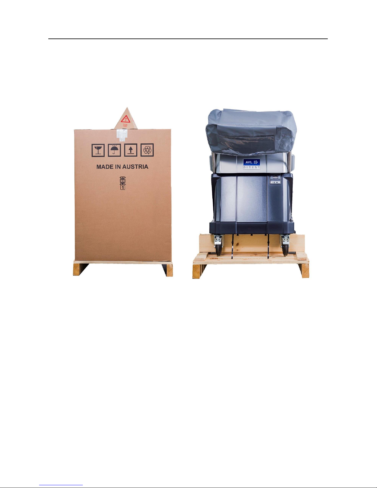
Fig. 2-1 Packaging VAS 581 009
1. Cut the packaging tape and remove the cardboard box.
Keep the cardboard box in case you need to return the device.
2. Carefully remove the protective foil from the VAS 581 009.
3. Use the scissors/side cutter to cut the four zip ties used to additionally secure the
VAS 581 009 to the pallet.
Page 9
Scope of delivery
VAS 581 009 unpacking instructions, placing into service, quick start guide
V2.00 05/18 All rights reserved.
8
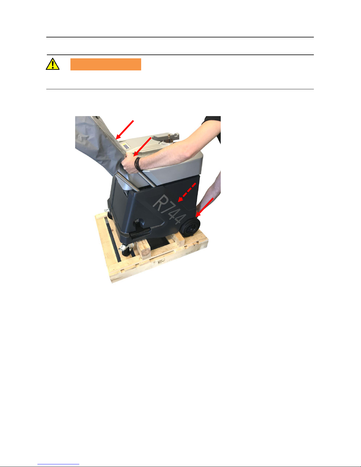
WARNING
Danger of crushing
The VAS 581 009 can topple from the pallet.
4. Carefully lift the VAS 581 009 from the pallet with the help of another person.
Fig. 2-2
Page 10
Scope of delivery
VAS 581 009 unpacking instructions, placing into service, quick start guide
V2.00 05/18 All rights reserved.
9
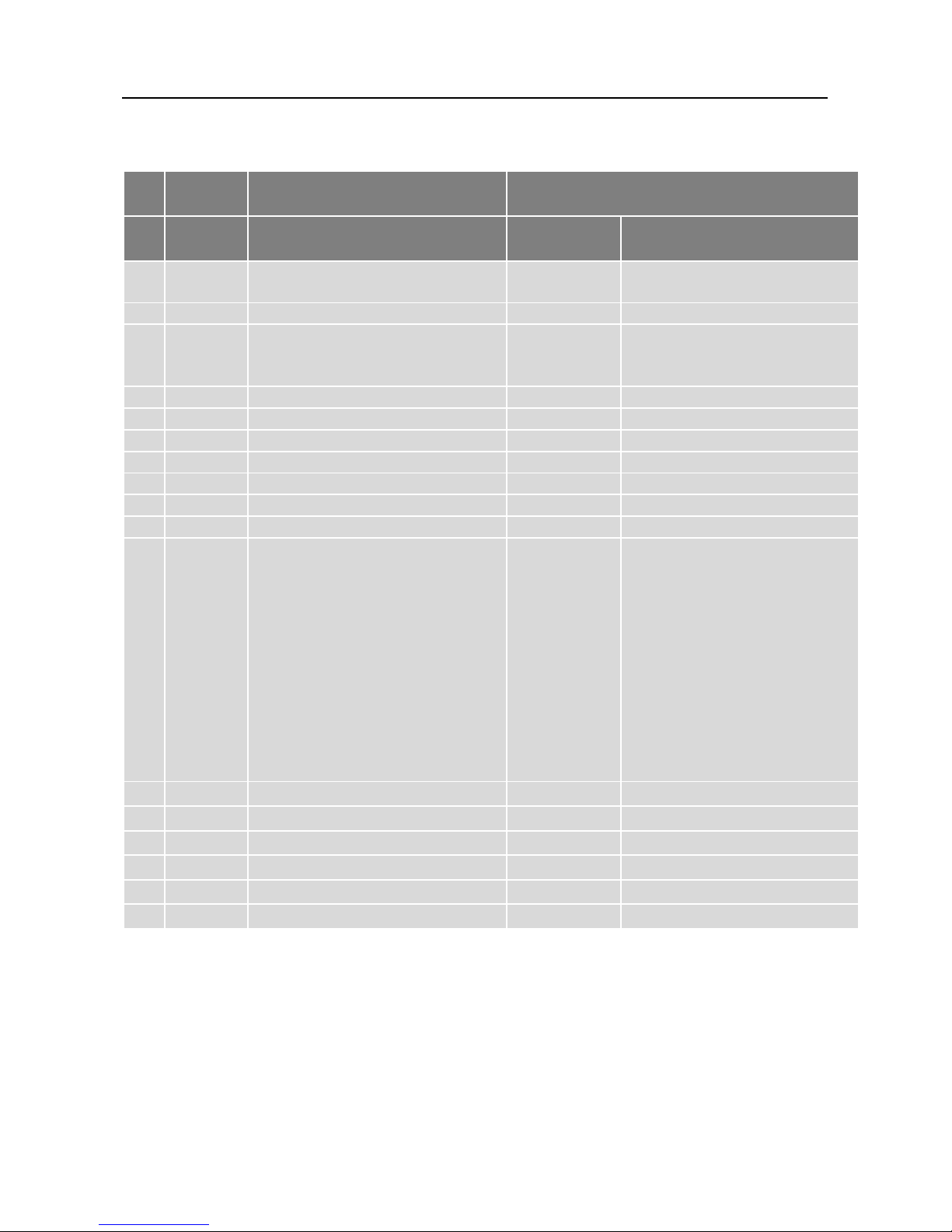
3 Scope of delivery
No. VAS
No.
Components
Item number
AVL
DiTEST
VOLKSWAGEN
1. Basic device VAS 581 009
cplt.
VS9155
ASE VAS 581 009 00 000
2. Operating instructions on CD
BO7960
3. Unpacking instructions, placing
into service instructions, quick
start guide, printed
AT7912EN
4. Inspection log book, printed
AT7914EN
5. Quick connector CO2 HP red
GE7520
6. Quick connector CO2 LP blue
GE7522
7. Filling hose CO2 HP red
SS7520
8. Filling hose CO2 LP blue
SS7521
9. Cover
MK7532
10. Acceptance report
11. Cylinder adapter W21, 8x1/14"
incl. seal
for connecting the R744
cylinder to the VAS 581 009
Notice:
It is possible that the supplied
cylinder adapter is not
compatible with a cylinder
available in your country. This
is why we offer a variety of
different adapters. See
"Available accessories".
DN7469
12. Protective goggles
GE7432
13. Protective gloves
GE7435
14. Cylinder adapter seal
DA7451
15. Printing paper
HP7003
16. Power cable EU
EX7075
17. Heating tape
BV8313
Page 11
Placing into service
VAS 581 009 unpacking instructions, placing into service, quick start guide
V2.00 05/18 All rights reserved.
10
4 Placing into service
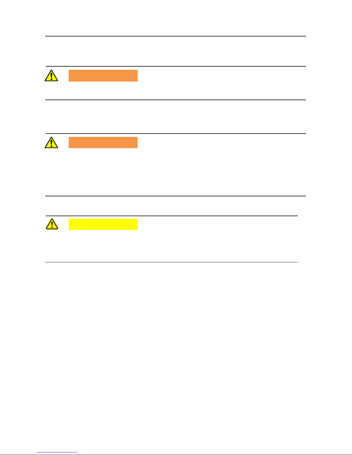
WARNING
Placing into service must be performed by qualified personnel under strict observance of
these instructions.
4.1 Installation location / stability
WARNING
Make sure that the VAS 581 009:
is horizontal and stable
is located in a room with adequate ventilation and/or air exchange
is at least 10 cm away from other objects
is protected against rain, excessive humidity, direct sunlight and/or excessive dust
is not operated in explosive environments
CAUTION
Temperature equalisation
If the VAS 581 009 is delivered in winter, it must be ensured that no condensation can
occur inside the device. This is why we request that you leave the device standing
unplugged at the site of use for about three hours.
Page 12
Placing into service
VAS 581 009 unpacking instructions, placing into service, quick start guide
V2.00 05/18 All rights reserved.
11
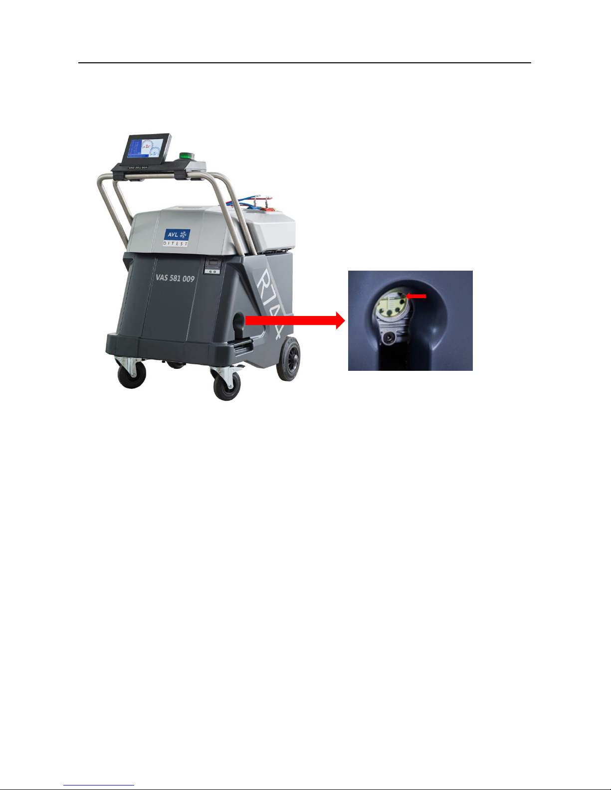
4.2 Checking the vacuum pump oil
Check the oil level through the gauge glass. Top op with vacuum pump oil if necessary;
see operating instructions, Sec. 5.2.1.
Fig. 4-1 Checking the vacuum pump oil
4.3 Power connection
Use the supplied power cable to connect the VAS 581 009.
Connect the power cable to the power supply.
Page 13
Placing into service
VAS 581 009 unpacking instructions, placing into service, quick start guide
V2.00 05/18 All rights reserved.
12
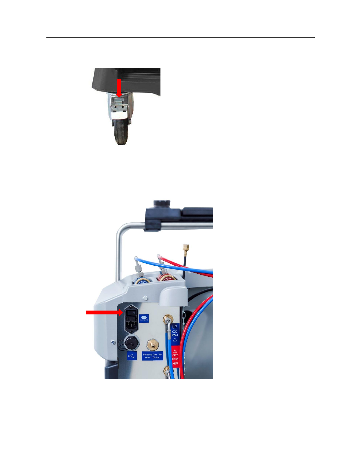
4.4 Switching on the VAS 581 009
1. Apply the wheel brakes.
Fig. 4-2 Applying the wheel brakes
2. Switch on the VAS 581 009.
Fig. 4-3
Page 14
Placing into service
VAS 581 009 unpacking instructions, placing into service, quick start guide
V2.00 05/18 All rights reserved.
13
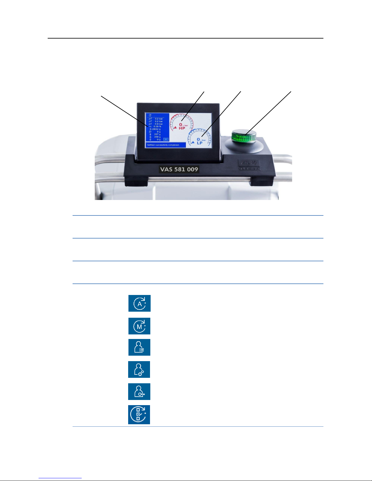
User interface
The user interface is controlled via a multi-functional dial. The individual functions
(buttons) are selected by turning the dial. To start a function, the dial must be
pressed.
Fig. 4-4
HP High Pressure
High pressure HP display of the refrigerating agent circuit
LP Low Pressure
Low pressure LP display of the refrigerating agent circuit
Multi-functional dial
To select and start a function, see below.
Operating modes
Automatic mode
Operating instructions, Sec. 3 "Automatic mode"
Manual mode
Operating instructions, Sec. 4 "Manual mode"
Settings
Operating instructions, Sec. 5 "Settings"
Maintenance
Operating instructions, Sec. 6 "Maintenance"
Service
Operating instructions, Sec. 7 "Service"
Overview
Operating instructions, Sec. 8 "Overview"
1
2
3
4
4
1 2 3
Page 15
Placing into service
VAS 581 009 unpacking instructions, placing into service, quick start guide
V2.00 05/18 All rights reserved.
14
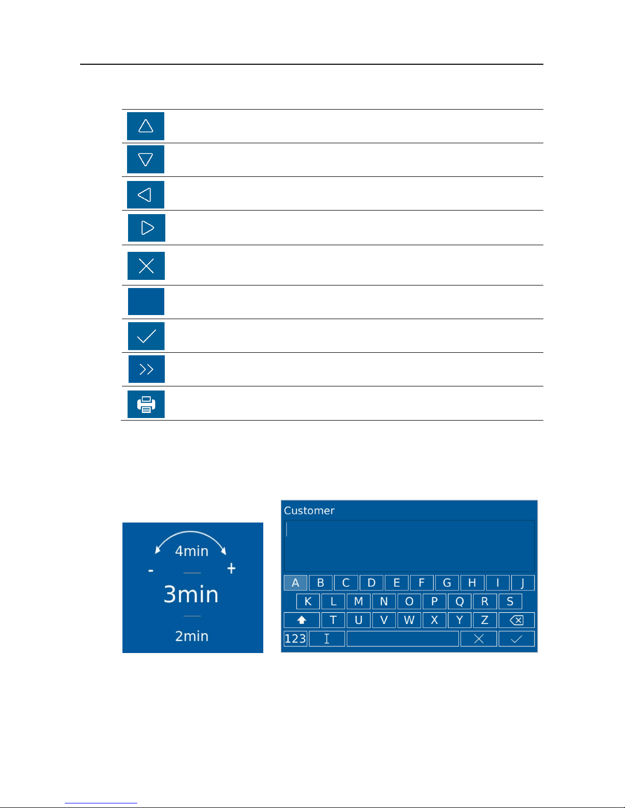
User prompts
Up
Selects previous function
Down
Selects next function
Back
Goes back one step.
Start
Starts functions.
Cancel
Cancels an ongoing operation.
Confirms questions with "No".
RESET
Resets values.
OK
Confirms questions with "Yes" or "OK".
Next
Continues to the next step.
Print
Prints logs.
Text and number inputs
If a number or letter is expected as an input, turning the dial will show the letters
and numbers in sequential order. Pressing the dial will select the letter or number.
Fig. 4-5 Example input
RESET
Page 16
Placing into service
VAS 581 009 unpacking instructions, placing into service, quick start guide
V2.00 05/18 All rights reserved.
15
Multi-functional dial
The multi-functional dial is equipped with an indicator.
Meaning of the indicator:
Meaning
Indicator state
System start
Blue
Status OK / completed
Green
Ongoing process
Yellow
User information
Yellow flashing (1-2 Hz)
Error
Red flashing (1-2 Hz)
System error
Red fast flashing (10 Hz)
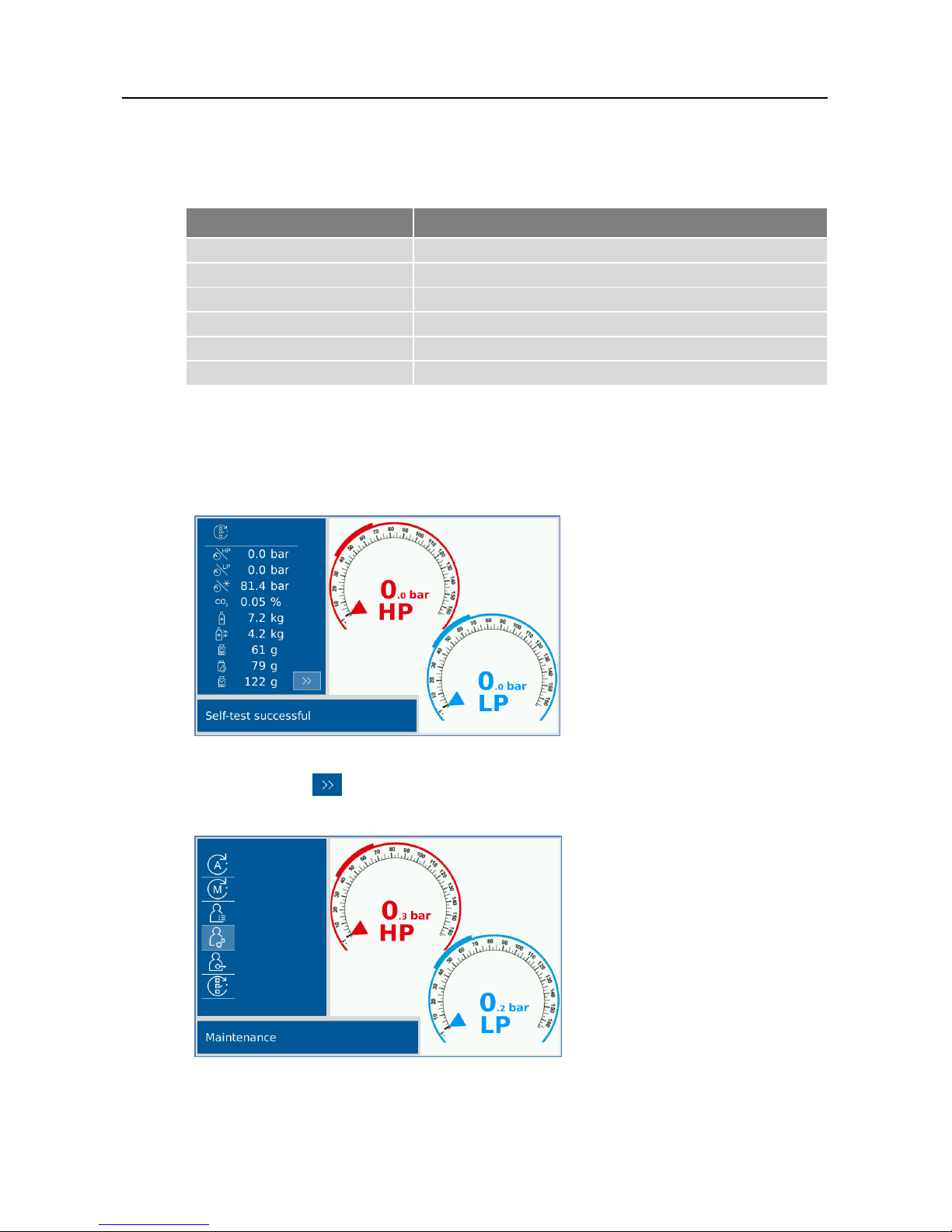
3. Self-test is being carried out automatically.
4. The following message appears after a successful self-test.
Fig. 4-6 Self-test successful
5. Continue with .
6. You are in the main menu.
Fig. 4-7 Main menu
Page 17
Placing into service
VAS 581 009 unpacking instructions, placing into service, quick start guide
V2.00 05/18 All rights reserved.
16
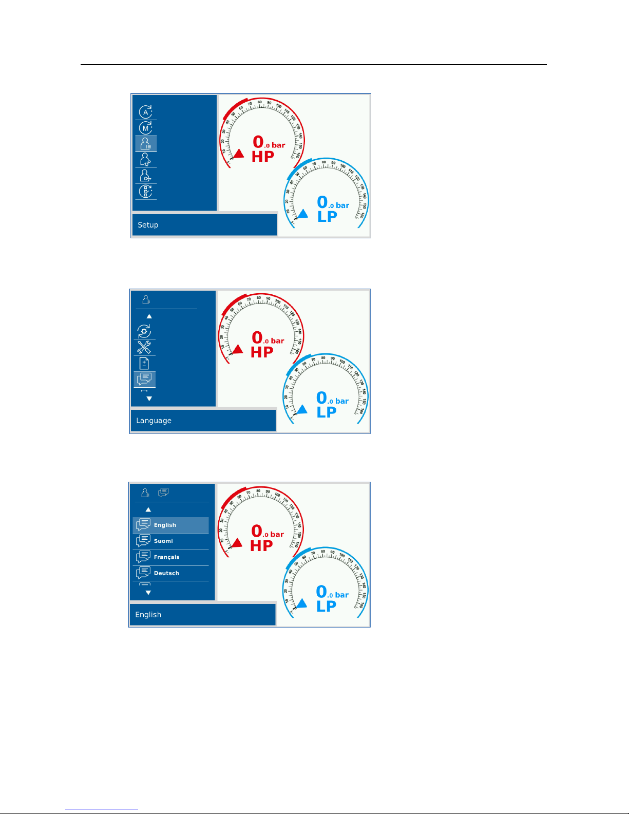
7. Tap Settings.
Fig. 5-8 Main menu - Settings
8. Tap Language.
Fig. 5-9 Settings - Language
9. Select your language.
Fig. 5-10 Language - Language selection
10. The VAS 581 009 restarts and performs a self-test after a language has been
selected.
Page 18
Placing into service
VAS 581 009 unpacking instructions, placing into service, quick start guide
V2.00 05/18 All rights reserved.
17
4.5 Pressure zeroing
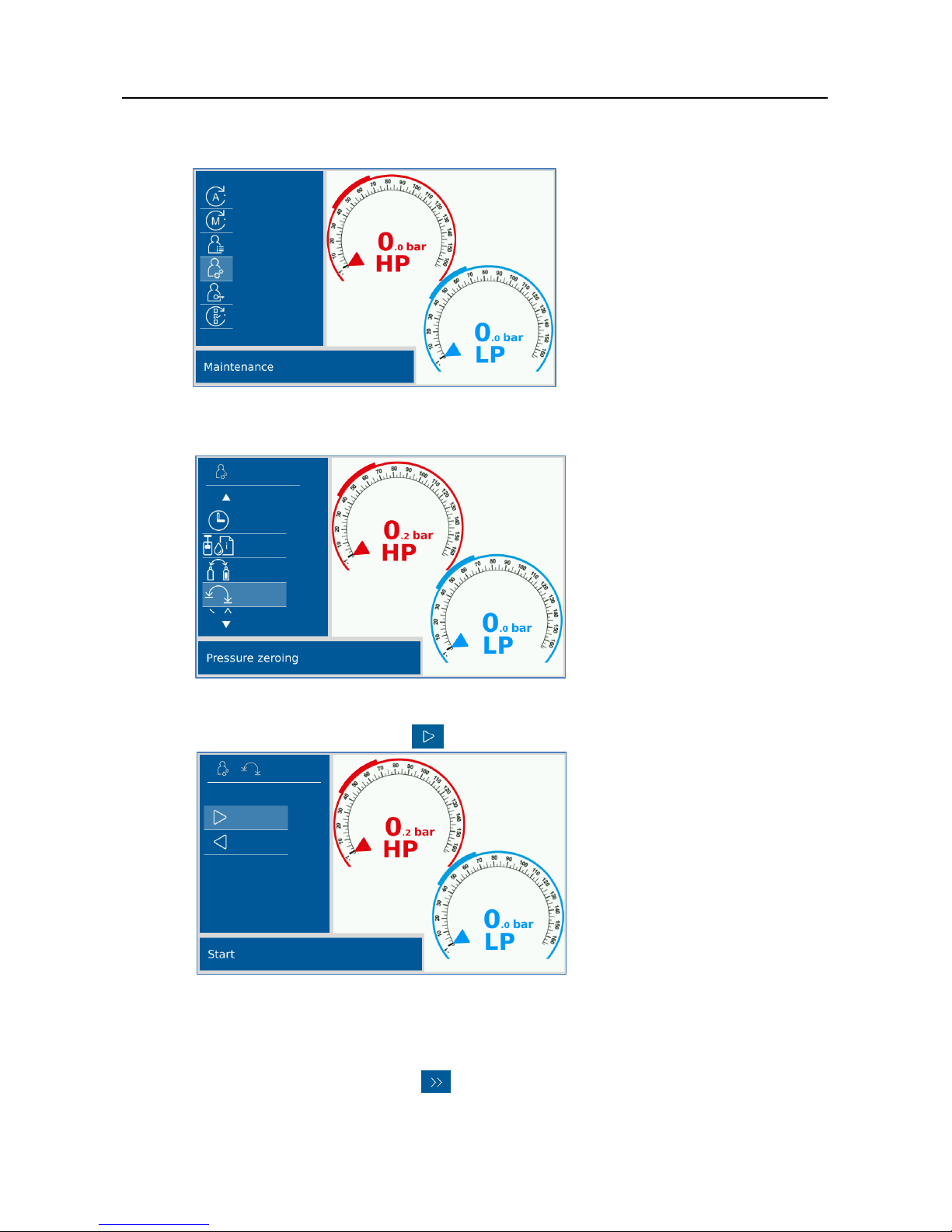
1. Select Maintenance in the main menu.
Fig. 4-11 Maintenance
2. Select Reset to zero.
Fig. 4-12 Pressure zeroing
3. Start pressure zeroing with .
Fig. 4-13 Pressure zeroing - Start
Pressure zeroing takes about 60 seconds. The counter is displayed. Wait until
the process is complete.
4. "Pressure zeroing" is complete.
5. Exit "Pressure zeroing" with .
Page 19
Placing into service
VAS 581 009 unpacking instructions, placing into service, quick start guide
V2.00 05/18 All rights reserved.
18
4.6 Oil/UV additive scales zeroing
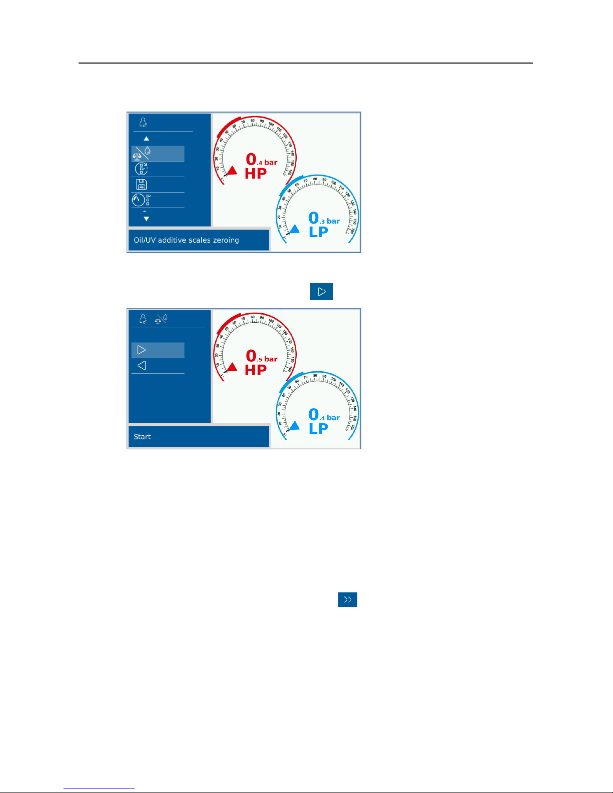
1. Select Reset Oil/UV additive scales to zero.
Fig. 4-14 Oil/UV additive scales zeroing
2. Start Oil/UV additive scales zeroing .
Fig. 4-15 Scales zeroing
Follow the instructions on the display. (e.g. mount empty oil/UV additive
containers, etc.).
Note:
The mounted oil containers must be completely empty for zeroing. If this is not
the case, an error message may occur during zeroing.
3. "Oil/UV additive scales zeroing" is complete.
4. Exit "Oil/UV additive scales zeroing" with .
Page 20
Placing into service
VAS 581 009 unpacking instructions, placing into service, quick start guide
V2.00 05/18 All rights reserved.
19
4.7 Connecting the refrigerating agent cylinder CO2 (R744)
NOTICE
The VAS 581 009 is suitable for standard CO2 (R744) refrigerating agent cylinders with a
built-in riser tube. The following cylinder sizes can be used: 5 kg, 6 kg, 10 kg or 20 kg.
Required purity equal or better than carbon dioxide 3.0 (99.9% purity).
Refrigerating cylinders can vary in size and design depending on the country. In these
instructions the two most common types are described.
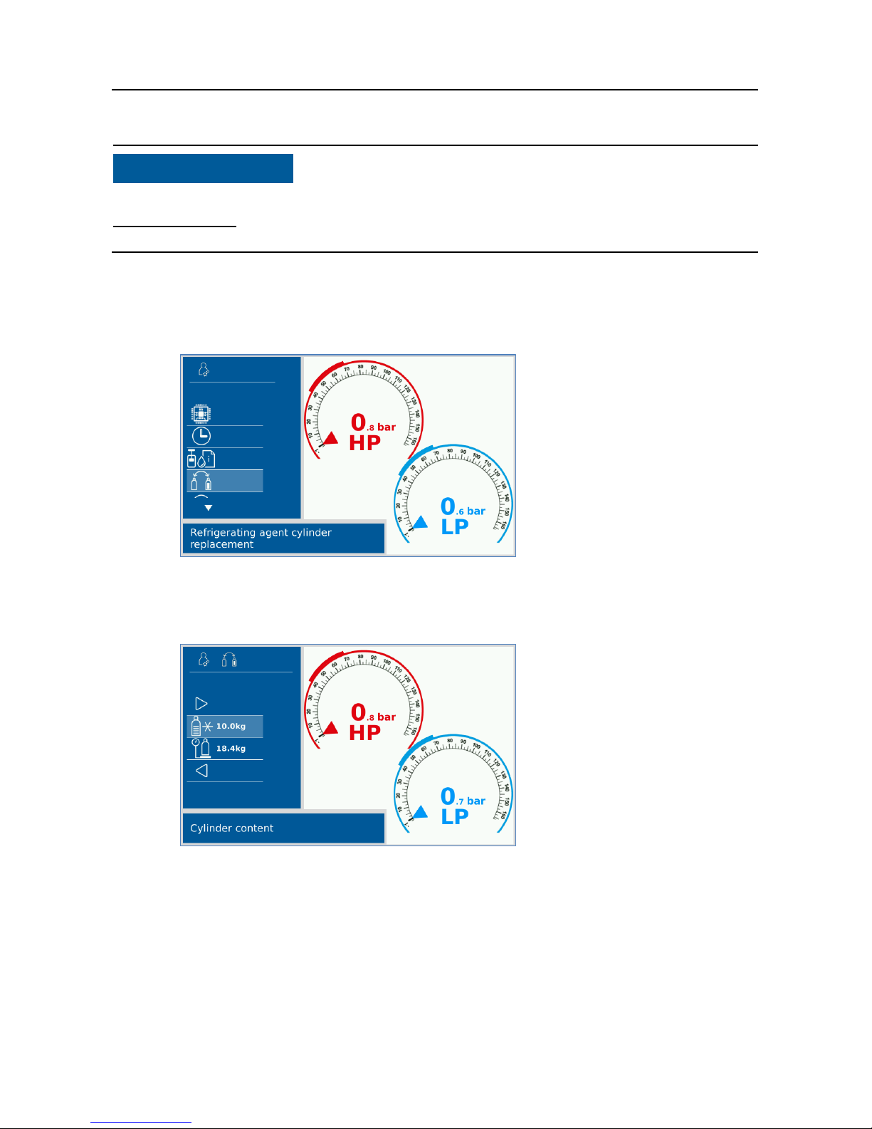
1. Select Replace refrigerating agent cylinder in the maintenance menu.
Fig. 4-16 Replacing refrigerating agent cylinder
2. Now select Cylinder content.
Fig. 4-17 Replacing refrigerating agent cylinder
Page 21
Placing into service
VAS 581 009 unpacking instructions, placing into service, quick start guide
V2.00 05/18 All rights reserved.
20
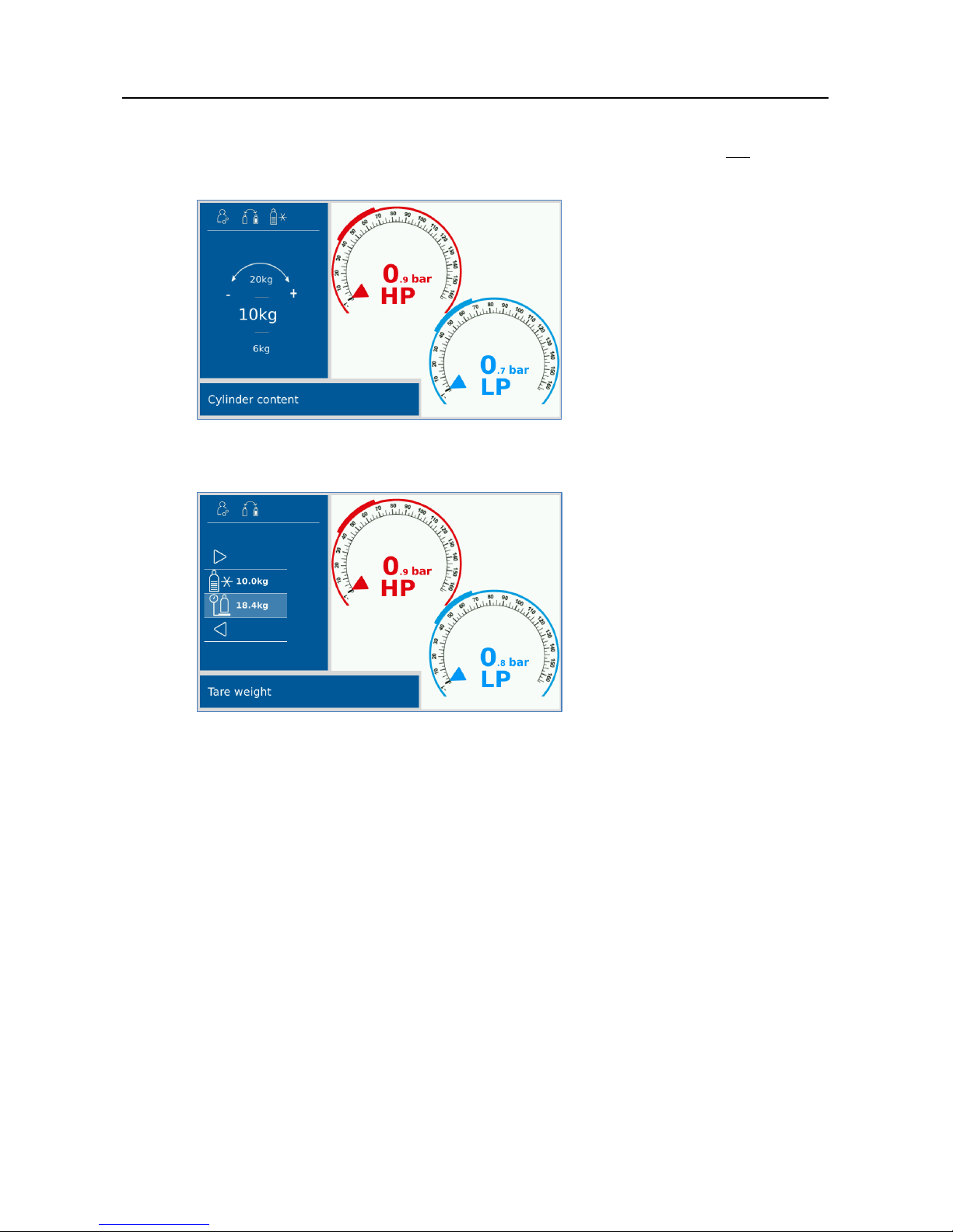
3. Enter the weight of the cylinder content.
(= nominal quantity of the content / nominal capacity of the cylinder, not the
actual cylinder capacity!) Incorrect entries inevitably result in incorrect
calculations of the available/usable cylinder capacity.
Fig. 4-18 Cylinder capacity
4. Select tare weight.
Fig. 4-19 Tare weight
Page 22
Placing into service
VAS 581 009 unpacking instructions, placing into service, quick start guide
V2.00 05/18 All rights reserved.
21
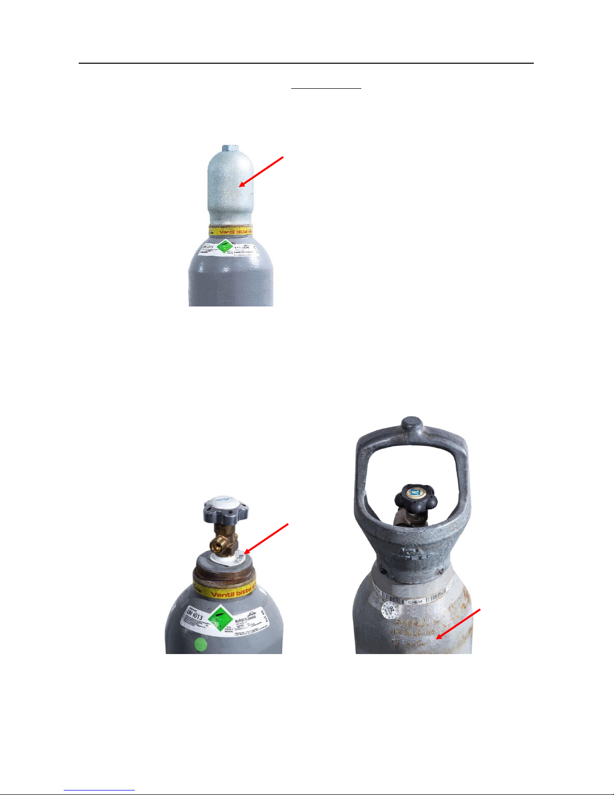
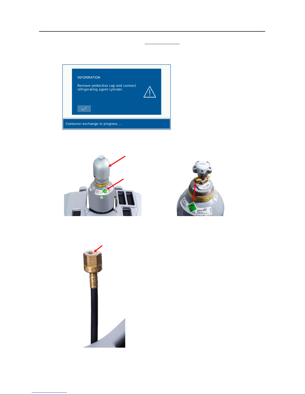
5. Refrigerating agent cylinder with protective cap:
a) In order to read the tare weight, the protective cap must be removed from the
refrigerating agent cylinder.
Fig. 4-20 Protective cap
b) Note down the tare weight.
The tare weight represents the net weight of the used cylinder (empty).
This weight is usually shown on the
cylinder, sometimes embossed.
Fig. 4-21 Ttare weight
Page 23
Placing into service
VAS 581 009 unpacking instructions, placing into service, quick start guide
V2.00 05/18 All rights reserved.
22
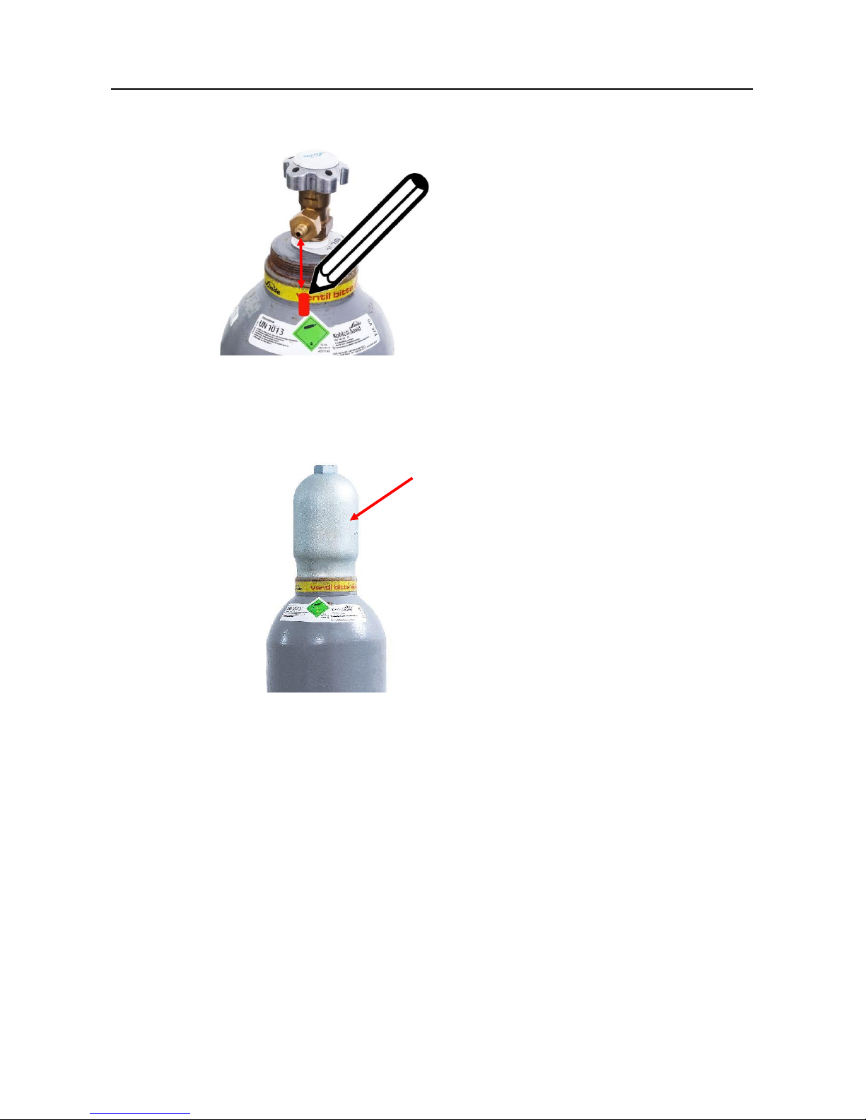
c) Mark the location of the outlet valve on the refrigerating agent cylinder.
Fig. 4-22 Mark
d) Re-attach the protective cap.
Fig. 4-23 Protective cap
Page 24
Placing into service
VAS 581 009 unpacking instructions, placing into service, quick start guide
V2.00 05/18 All rights reserved.
23
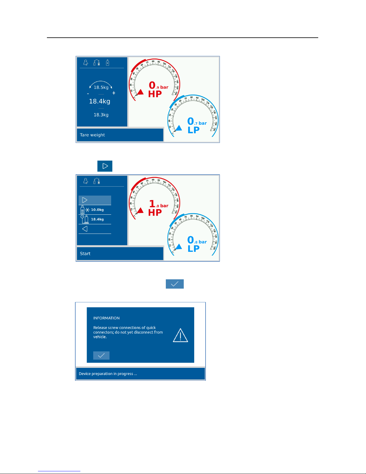
6. Enter the tare weight.
Fig. 4-24 Tare weight
7. Press to continue replacing the cylinder.
Fig. 4-25 Start
8. Skip this message by clicking .
The hose is automatically emptied.
Fig. 4-26 Unscrew the screw connection
Page 25
Placing into service
VAS 581 009 unpacking instructions, placing into service, quick start guide
V2.00 05/18 All rights reserved.
24
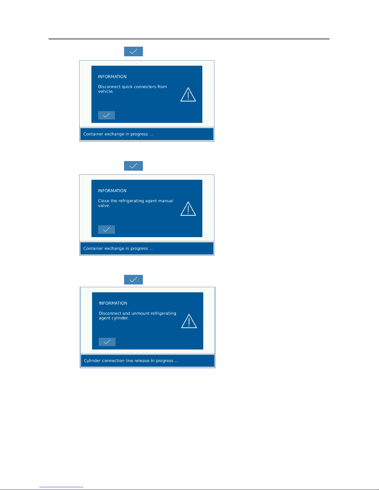
9. Continue with .
Fig. 4-27 Disconnecting the quick connectors
10. Continue with .
Fig. 4-28 Close manual valve
11. Continue with .
Fig. 4-29 Disconnecting refrigerating agent cylinder
Page 26
Placing into service
VAS 581 009 unpacking instructions, placing into service, quick start guide
V2.00 05/18 All rights reserved.
25
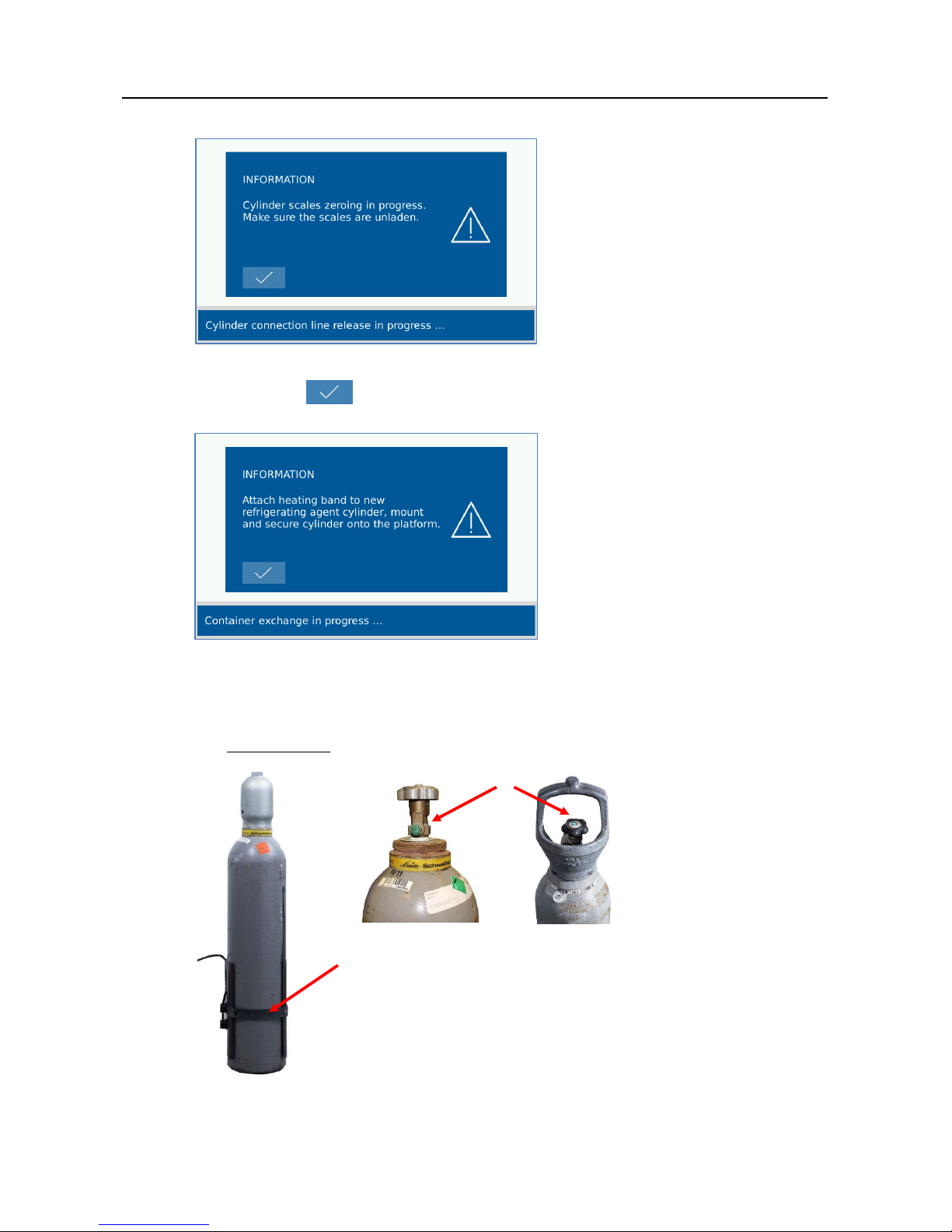
12. Follow the instructions. Make sure the scales are unladen.
Fig. 4-30 Information
13. Continue with .
14. Follow the instruction.
Fig. 4-31 Information
a) Attach the cylinder heater (heating band) around the lower third of the cylinder.
Important: The closure of the cylinder heater must be located on the
opposite side of the outlet valve.
Fig. 4-32 Heating band
Outlet valve
Page 27
Placing into service
VAS 581 009 unpacking instructions, placing into service, quick start guide
V2.00 05/18 All rights reserved.
26
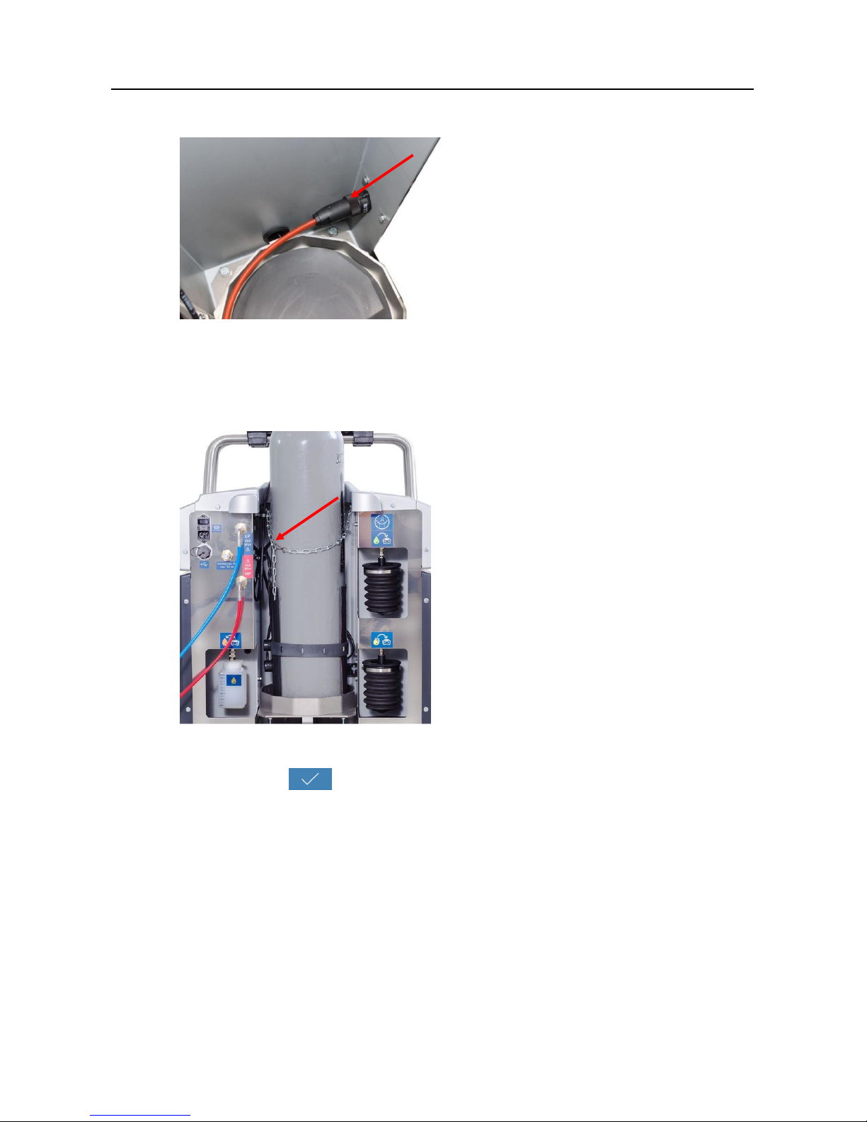
b) Make sure that the cylinder heater (heating band) is connected.
Fig. 4-33 Connecting heating band
c) Place the new refrigerating agent cylinder onto the refrigerating agent scales.
Note that the bottle heating cable is not placed on the balance during the
assembly of the bottle. Attach the securing chain.
Fig. 4-34 Securing chain
15. Continue with .
Page 28
Placing into service
VAS 581 009 unpacking instructions, placing into service, quick start guide
V2.00 05/18 All rights reserved.
27
16. Refrigerating agent cylinder with protective cap:
Remove the protective cap.
Make sure that the connection of the refrigerating agent cylinder is facing the
device and not away.
Fig. 4-35 Information
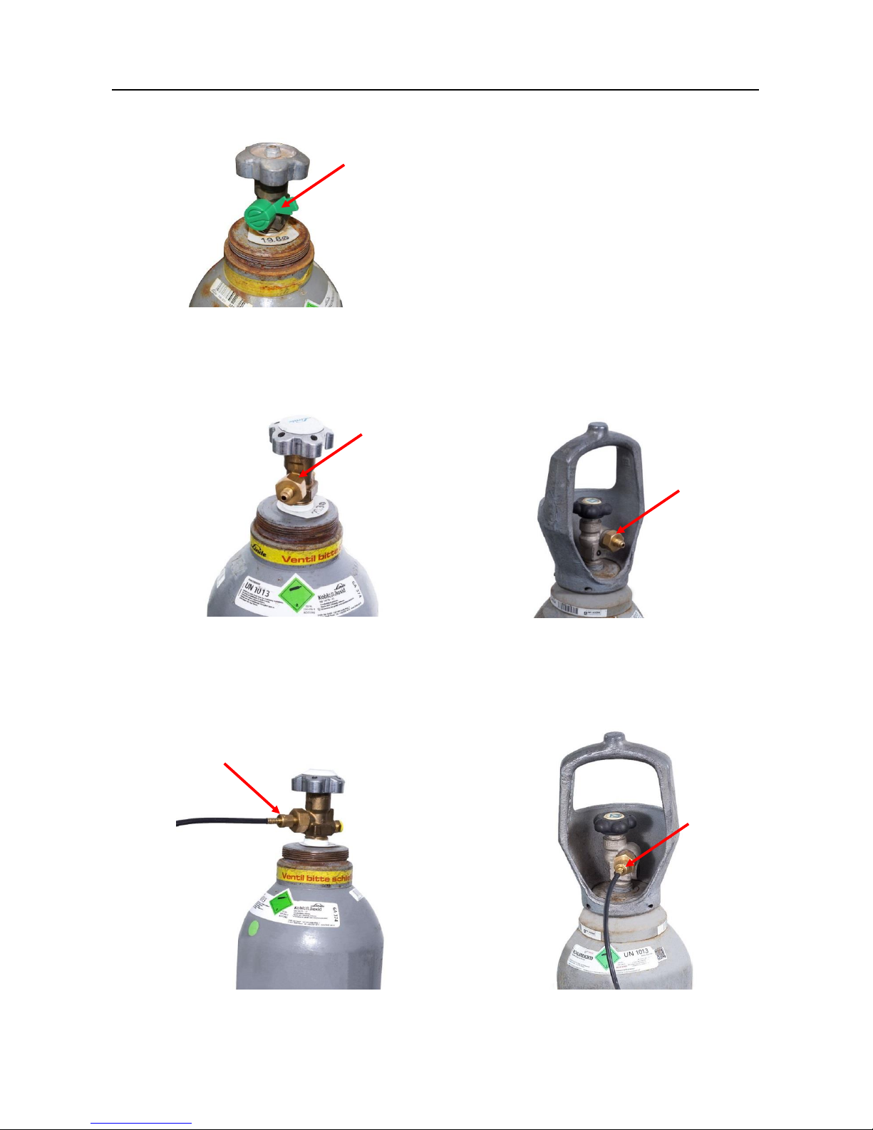
17. Zeroing and hose emptying are performed automatically.
Fig. 4-36 Refrigerating agent cylinder
18. Remove the hose from the plastic cap if necessary.
Fig. 4-37 Plastic cap
Page 29
Placing into service
VAS 581 009 unpacking instructions, placing into service, quick start guide
V2.00 05/18 All rights reserved.
28
19. Remove the plastic cap on the outlet valve if necessary.
Fig. 4-38 Refrigerating agent cylinder with Plastic cap
20. Attach the supplied cylinder adapter.
Torque: 30 … 32 Nm, max. 35 Nm.
Fig. 4-39 Refrigerating agent cylinder with cylinder adapter
21. Connect the hose to the cylinder adapter. Spanner width: 14 mm
Torque: 16 … 18 Nm, max. 20 Nm.
Fig. 4-40 Connect the hose to the cylinder adapter
Page 30
Placing into service
VAS 581 009 unpacking instructions, placing into service, quick start guide
V2.00 05/18 All rights reserved.
29
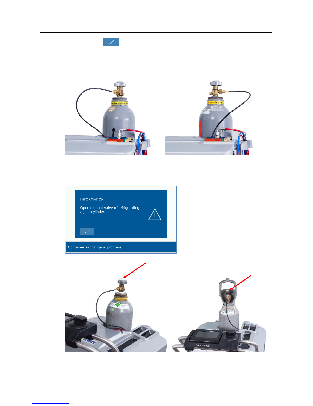
22. Continue with .
23. Make sure that the hose/hose connection is facing the device.
It must not lead away from the rear of the device.
This could lead to a faulty measurement of the cylinder weight.
Fig. 4-41 Hose connection
24. Follow the instructions and open the manual valve of the refrigerating agent
cylinder.
Fig. 4-42 Information
Fig. 4-43 Manual valve
Page 31

Placing into service
VAS 581 009 unpacking instructions, placing into service, quick start guide
V2.00 05/18 All rights reserved.
30
25. End the replacement of the refrigerating agent cylinder with .
The system is flushed with CO2, i.e. the filling hoses are first flooded with CO2,
then the CO2 is discharged. The VAS 581 009 must not be connected to the
vehicle at this time.
26. Exit the menu with .
27. Select to return to the main menu.
28. The VAS 581 009 is now ready for use.
Page 32
Available accessories
VAS 581 009 unpacking instructions, placing into service, quick start guide
V2.00 05/18 All rights reserved.
31
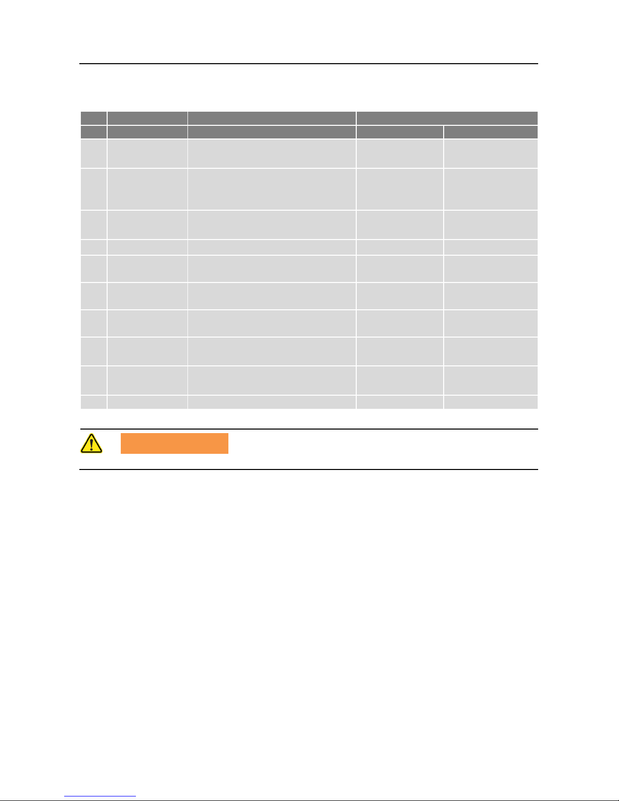
5 Available accessories
No.
VS No.
Components
Item number
AVL DiTEST
VOLKSWAGEN
1. Vacuum pump oil 500 ml
(2 units per package)
GE7427
2. Printer paper 57 mm,
(minimum order quantity: 5
units
HP7003
3. Cylinder heater (heating band)
incl. connector
BV8261
4. External pressure test set
BO7948
5.
Cylinder adapter incl. seal:
W21.7x1/14"
DN7470
6.
Cylinder adapter incl. seal:
0.860"x14TPI
DN7471
7.
Cylinder adapter incl. seal:
G3/4"
DN7472
8.
Cylinder adapter incl. seal:
0.825"x14NGO
DN7473
9.
Cylinder adapter incl. seal:
W27x2mm
DN7474
10. Calibration kit BAS 581 009
BO7972
WARNING
Only use accessories approved by AVL DiTEST!
Page 33
Quick start guide
VAS 581 009 unpacking instructions, placing into service, quick start guide
V2.00 05/18 All rights reserved.
32
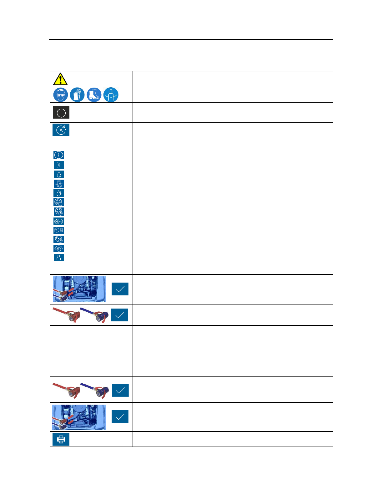
6 Quick start guide
OBSERVE SAFETY INSTRUCTIONS
Wear personal protective equipment!
Switch on VAS 581 009;
Self-test runs automatically.
Select "Automatic cycle" in main menu.
Enter parameters:
- Configuration name
- Refrigerating agent [g]
- Oil quantity [g]
- Oil filling mode [REC+/ABS/NO]
- UV additive quantity [g]
- Vacuum time [min]
- Vacuum test time [min]
- Connection type [LP / HP+LP]
- Pressure test [OFF / 10% / 20%]
- Pressure test time [min]
- Pressure loss [mbar]
- Customer data
Check and confirm inputs
Connect quick connectors with vehicle and confirm
Open gas supply of quick connectors
"Automatic cycle"
runs automatically
Automatic cycle
- Safety self-test
- Drain refrigerating agent
- Vacuum generation
- Filling of air conditioning system
Close gas supply of quick connectors and confirm.
Hoses are emptied in VAS 581 009.
Disconnect quick connectors from vehicle and confirm.
Print report [Yes/No]
Page 34
Quick start guide
VAS 581 009 unpacking instructions, placing into service, quick start guide
V2.00 05/18 All rights reserved.
33
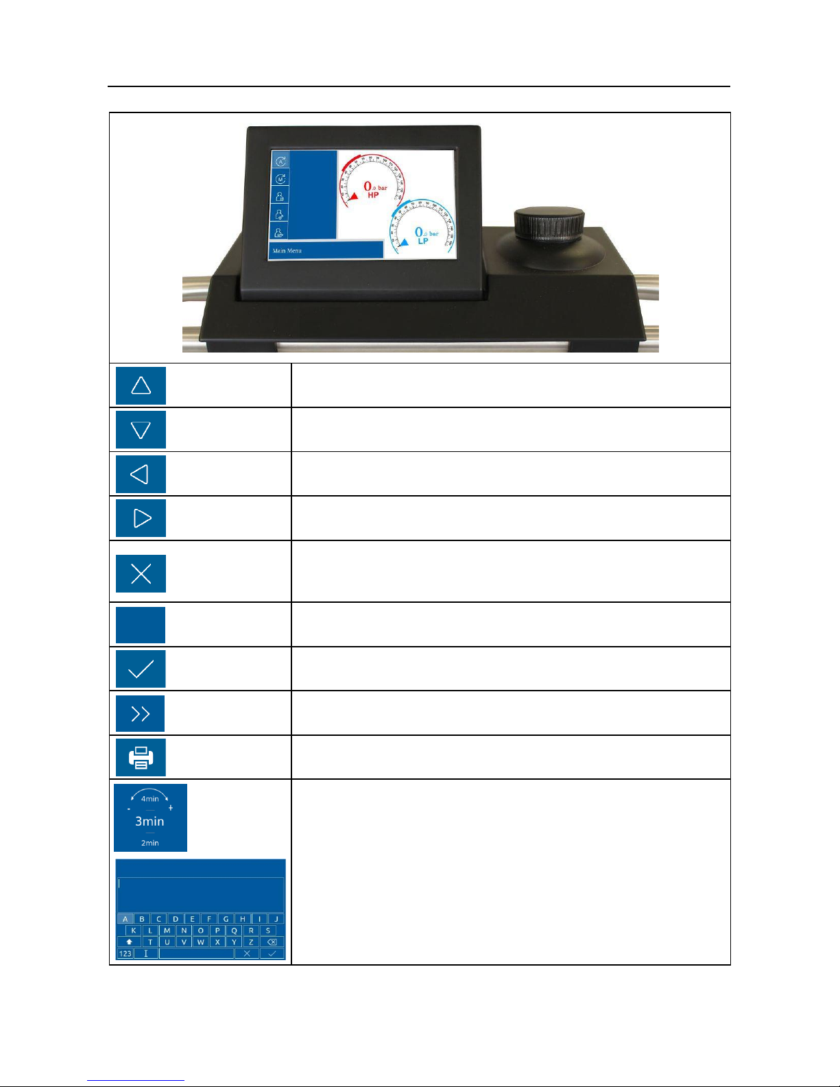
Up
Selects previous function
Down
Selects next function
Back
Goes back one step.
Start
Starts functions.
Cancel
Cancels an ongoing operation.
Confirms questions with "No".
RESET
Resets values.
OK
Confirms questions with "Yes" or "OK".
Next
Continues to the next step.
Print
Prints logs
Text and number inputs
If a number or letter is expected as an input, turning the dial
will show the letters and numbers in sequential order.
Pressing the dial will select the letter or number.
RESET
Page 35

Fault conditions
VAS 581 009 unpacking instructions, placing into service, quick start guide
V2.00 05/18 All rights reserved.
34
7 Fault conditions
In the case of an error, please proceed as follows:
Try to determine the cause and location of the error. Please refer to the
"Troubleshooting" section in the operating instructions before contacting your
service partner.
 Loading...