

Page 1
g
V
g
Volkswagen Phaeton
Стр. 1 из 6Front suspension, servicin
40 - 2
Front suspension, servicin
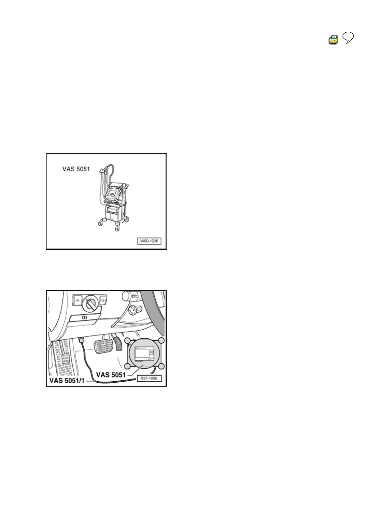
AS 5051, connecting and selecting functions
Special tools, equipment, testers, measuring
instruments and auxiliary items required
VAS 5051 Vehicle diagnosis, testing and information
system
Diagnostic cable VAS 5051/1 or VAS 5051/3
Warning!
During a test drive you must always secure
testing and measuring equipment on the back
seat.
These devices may be operated only by a
passenger during a test drive.
Page 2
g
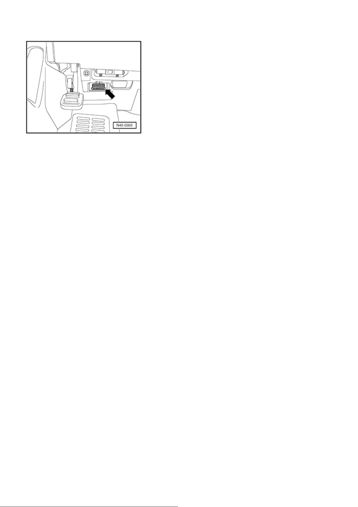
- Connect diagnosis cable connector VAS 5051/1 or VAS
5051/3 to diagnosis connection.
Стр. 2 из 6Front suspension, servicin
- Switch on tester
- arrow -
.
The tester is operational when it displays a picture of a car.
- Switch on ignition.
- Touch button/field for "Guided Fault Finding" on screen.
- Select one after another:
Brand
Type
Model year
Version
Engine code
- Confirm data entered.
Note:
Wait until tester has checked all control modules in
vehicle.
- Press Goto button and select "Function/component
selection" function
Follow information given on screen to start the desired
functions.
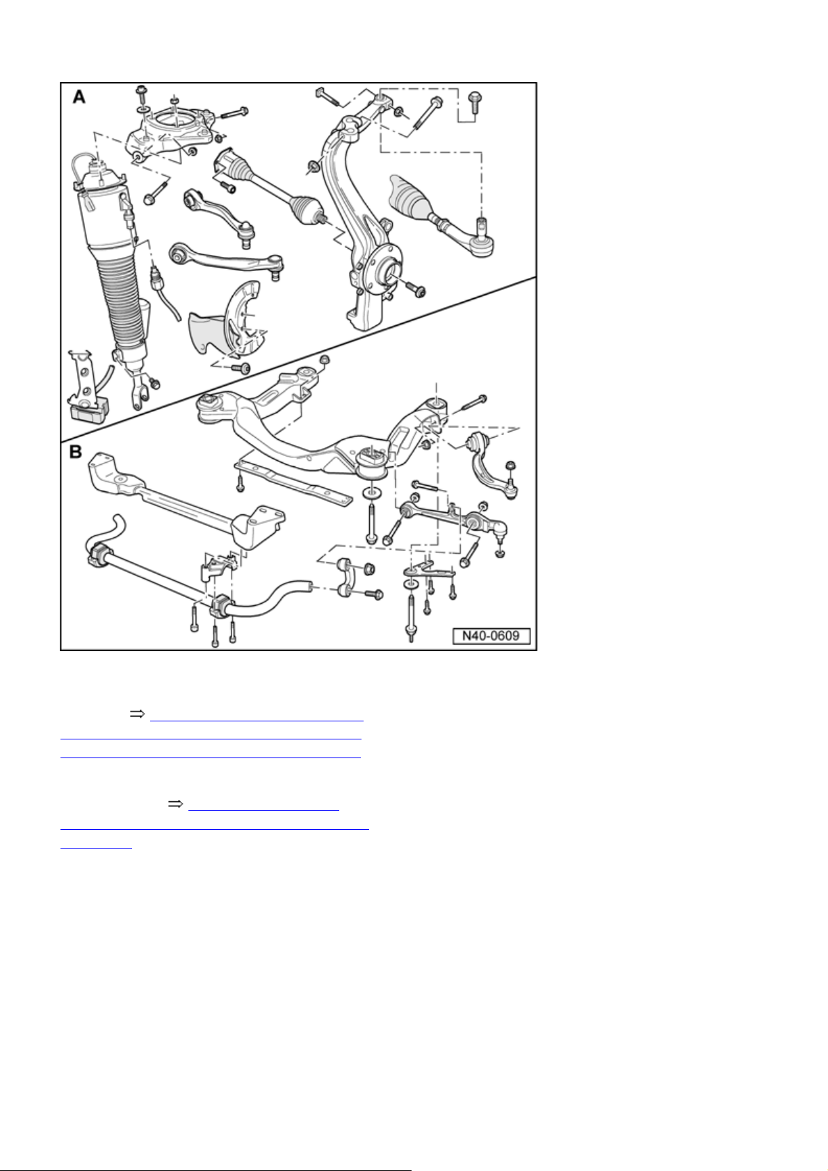
Front axle, overview
Page 3
Стр. 3 из 6Front suspension, servicin
g
A - Mounting bracket, upper links, air
spring strut, and wheel bearing
housing 40
-3, A - Mounting bracket,
upper links, air spring strut and wheel
bearing housings, assembly overview
B - Subframe, lower links, and
stabilizer bar 40-4, B - Subframe,
lower link, and stabilizer bar, assembly
overview
Note:
If vehicles with drive axle removed must be moved,
an outer joint must be installed first. Tighten outer
joint to 50 Nm, otherwise the wheel bearings will be
damaged.
Welding and straightening work on supporting or
wheel carrying components of suspension is not
permitted.
Page 4
Стр. 4 из 6Front suspension, servicin
g
Always replace self-locking nuts.
Always replaced corroded nuts/bolts.
Wheel bearing, lifting to curb weight position
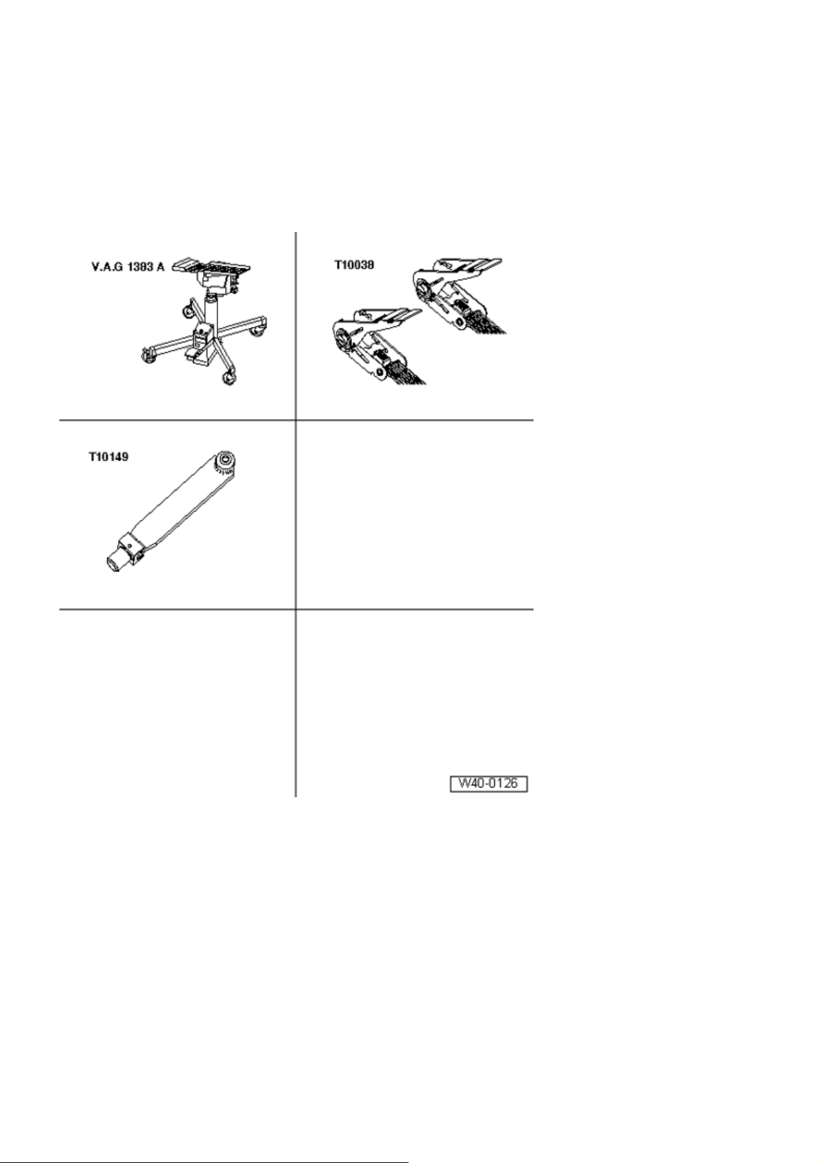
Special tools, testers and auxiliary items
required
engine/transmission jack V.A.G
1383 A
Tightening strap T10038
Wheel hub support T10149
Note:
Page 5
Always tighten all connecting bolts to suspension
p
y
!
g
g
parts with bonded rubber bushings in curb weight
position (unloaded).
Bonded rubber bushings have a limited twisting range.
Axle components with bonded rubber bushings must be
brought into installation position before tightening, which
corresponds to curb weight position when driving.
Otherwise, if you stress the bonded rubber bushing it will
lead to a shorter life span.
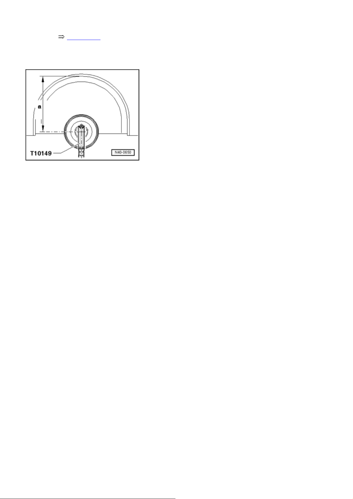
By raising the suspension on one side using the
engine/transmission jack V.A.G 1383 A and support
T10149 , this position will be simulated on the hoist.
Стр. 5 из 6Front suspension, servicin
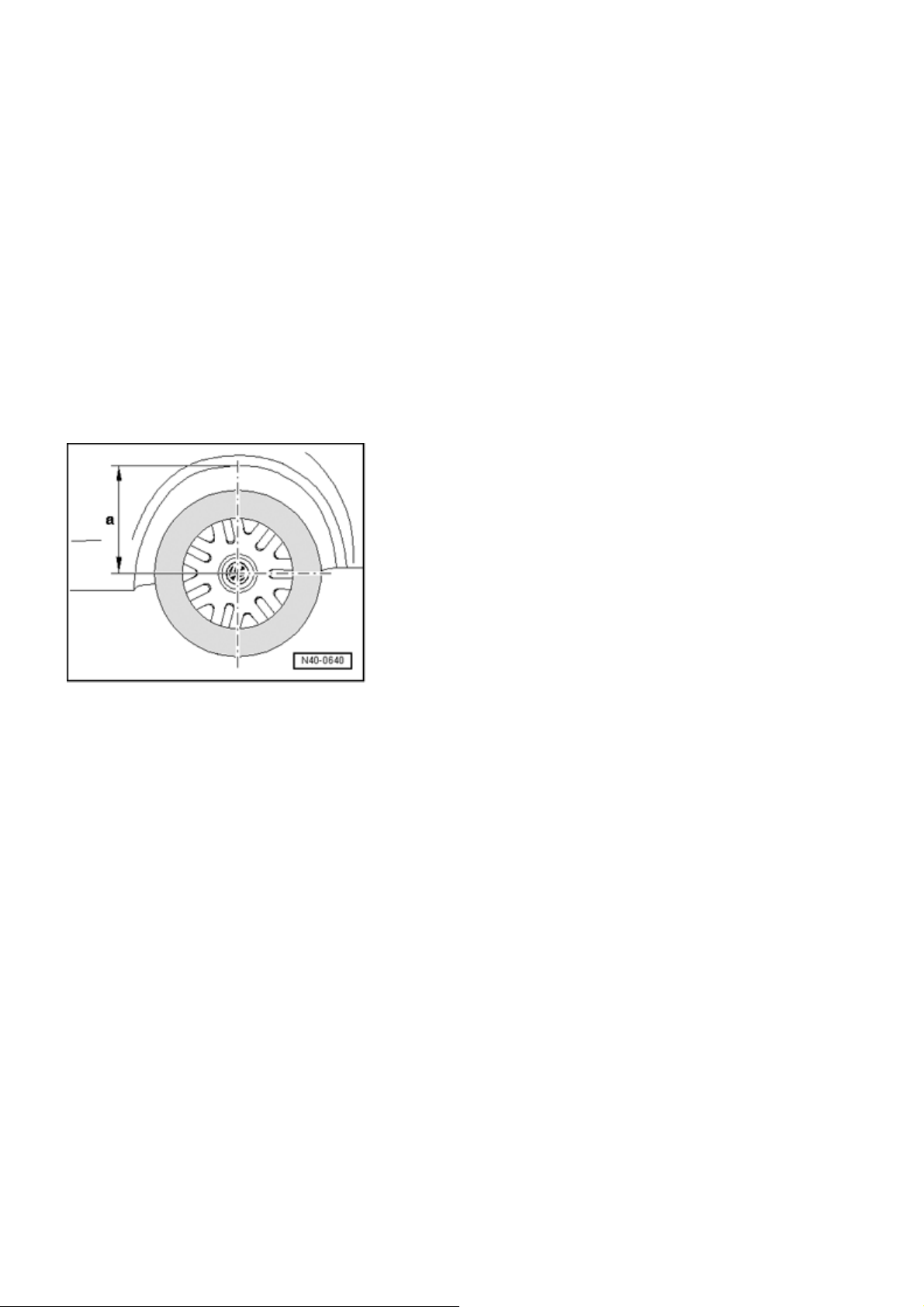
- Before beginning assembly, measure dimension
- a -
from
center of wheel to lower edge of wheelhousing using a tape
measure.
The measurement must be taken in the curb weight
osition (unloaded).
- Note measured value. This is needed for tightening bolts
and nuts.
Before the individual suspension is raised on one side, the
vehicle must be secured to the lifting arms on the hoist
using tensioning straps T10038 .
Caution!
If the vehicle is not secured, it ma
slip off the hoist
- Turn wheel hub until one of the wheel bolt holes is at 12
o'clock position. .
- Attach Wheel Hub Support T10149 to wheel hub with a
wheel bolt.
Only tighten respective bolts and nuts after dimension
- a - between wheel hub center and lower edge of wheel
housin
, measured before beginning of assembly, is
Page 6
j
g
Стр. 6 из 6Front suspension, servicin
g
achieved
Topic 40-2
.
- Raise wheel bearing housing using engine/transmission
ack V.A.G 1383 A until dimension
is achieved.
- a -
Lift wheel bearing housin
Caution!
Do not raise or lower the hoist if the
engine/transmission jack is under the vehicle.
Do not leave engine/transmission jack V.A.G 1383
A under vehicle any longer than necessary.
- Tighten respective nuts/bolts.
- Lower wheel bearing housing.
- Move engine/transmission jack V.A.G 1383 A below
vehicle away.
- Remove wheel hub support T10149 .
Page 7
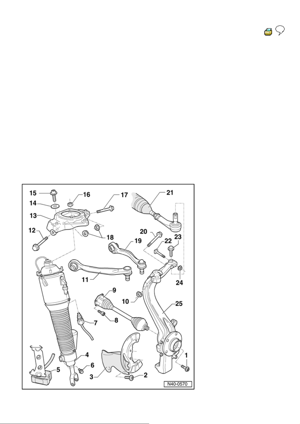
A - Mounting bracket, upper links, air spring strut
g
and wheel bearin
housings, assembly overview
Note:
If a vehicle has to be moved after removing the drive
axle, first install an outer joint and tighten this to 50
Nm, otherwise you will damage the wheel bearings.
Welding and straightening work on supporting or
wheel carrying components of the suspension is not
permitted.
Always replace self-locking hex head nuts.
Стр. 1 из 29A - Mounting bracket, upper links, air spring strut and wheel bearing housings, assembly over...
40 - 3
Always replaced corroded bolts and nuts.
Hex socket head bolt
Page 8
200 Nm plus an additional
g
1
180 (
Always replace
/ 2 turn)
Vehicle must not be raised
when tightenin
Torx bolt
9 Nm
Cover plate
Air spring strut
Стр. 2 из 29A - Mounting bracket, upper links, air spring strut and wheel bearing housings, assembly over...
Protective boot must not have
any indentations (be pressed
inward)
Removing and installing
40-3, Air spring strut removing
and installing
Wheel acceleration sensor
Left front wheel acceleration
sensor G337
Right front wheel acceleration
sensor G338
Check with Vehicle Diagnosis,
Testing and Information
System VAS 5051 in "Guided
Fault Finding"
Hex bolt
10 Nm
Air supply line
5 Nm
Clean connection before
loosening
Air escapes when
connections are loosened
Protect threaded connection
Page 9
from dirt
Multi-point socket head bolt
70 Nm
M 10 x 20
Pre-tighten to 10 Nm in
diagonal sequence
Drive axle
Hex nut
50 Nm
Self-locking
Стр. 3 из 29A - Mounting bracket, upper links, air spring strut and wheel bearing housings, assembly over...
Always replace
Upper front link
Can only be removed
together with mounting
bracket
Mounting bracket, removing
and installing 40-3,
Mounting bracket, removing
and installing
Bonded rubber bushings,
replacing 40-3, Upper link
bonded rubber bushing,
replacing
Hex bolt
Always replace
Mounting bracket
Removing and installing
40-3, Mounting bracket,
removing and installing
Washer
Multi-point socket head bolt
Observe tightening sequence
40-3, Tightening sequence,
Page 10
Hex nut
23 Nm
Hex bolt
Always replace
Hex nut
50 Nm and 90 (
air spring damper to body
50 Nm plus an additional 90
( 1 / 4 turn)
Always replace
1
/ 4 turn)
Стр. 4 из 29A - Mounting bracket, upper links, air spring strut and wheel bearing housings, assembly over...
Self-locking
Replace after every removal
Upper rear link
Can only be removed
together with mounting
bracket
Mounting bracket, removing
and installing 40-3,
Mounting bracket, removing
and installing
Bonded rubber bushings,
replacing 40-3, Upper link
bonded rubber bushing,
replacing
Hex bolt
On aluminum wheel bearing
Tie rod
Hex bolt
Hex bolt
7 Nm
housings, tighten against
driving direction
Page 11
Always replace
g
Hex nut
50 Nm
Self-locking
Always replace
Wheel bearing housing
Removing and installing
40-3, Wheel bearing housing,
removing and installing
Aluminum or steel, application
Parts catalog
Стр. 5 из 29A - Mounting bracket, upper links, air spring strut and wheel bearing housings, assembly over...
Air spring strut removing and installin
Page 12
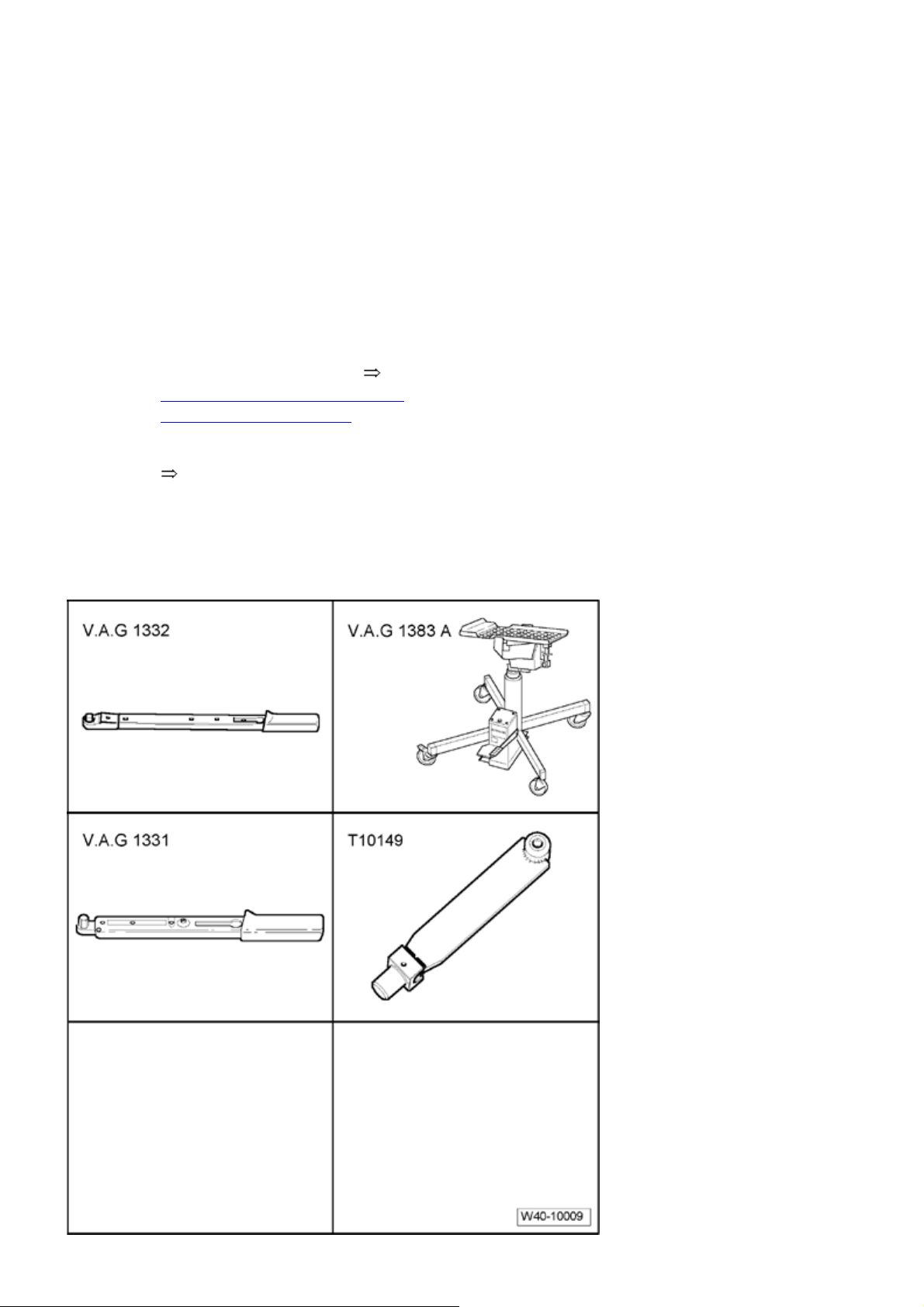
Special tools, testers and auxiliary items
required
Стр. 6 из 29A - Mounting bracket, upper links, air spring strut and wheel bearing housings, assembly over...
Torque wrench V.A.G 1331
Torque wrench V.A.G 1332
Engine/transmission jack V.A.G
1383 A
Wheel hub support T10149
Removing
Remove air spring strut together with mounting
bracket and upper links.
During assembly work, make sure that no indentations
form on boot of air spring strut!
- Remove front wheel.
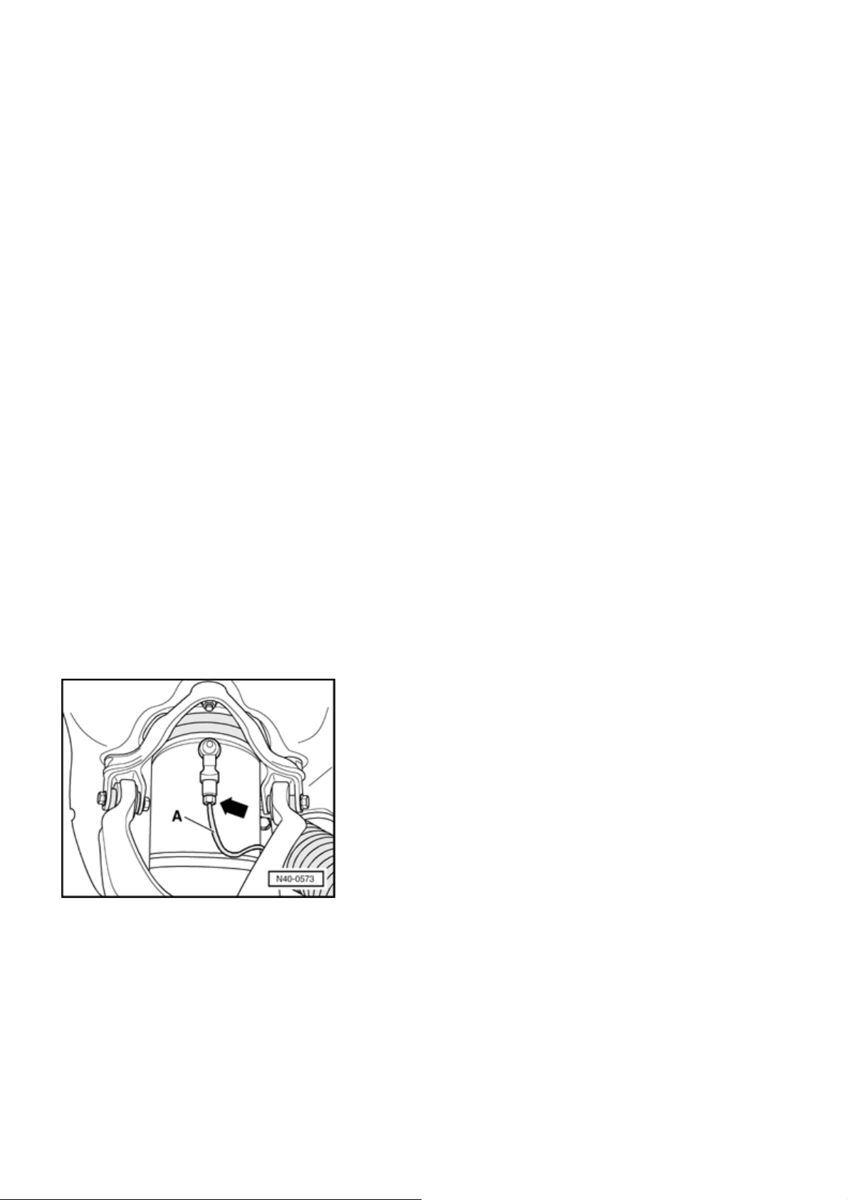
- Clean air line connection
- Remove air line
from air spring strut and then seal off
- A -
- arrow -
to air spring strut.
both connections.
- Open air line cable ties at air spring strut.
Page 13
j
Стр. 7 из 29A - Mounting bracket, upper links, air spring strut and wheel bearing housings, assembly over...
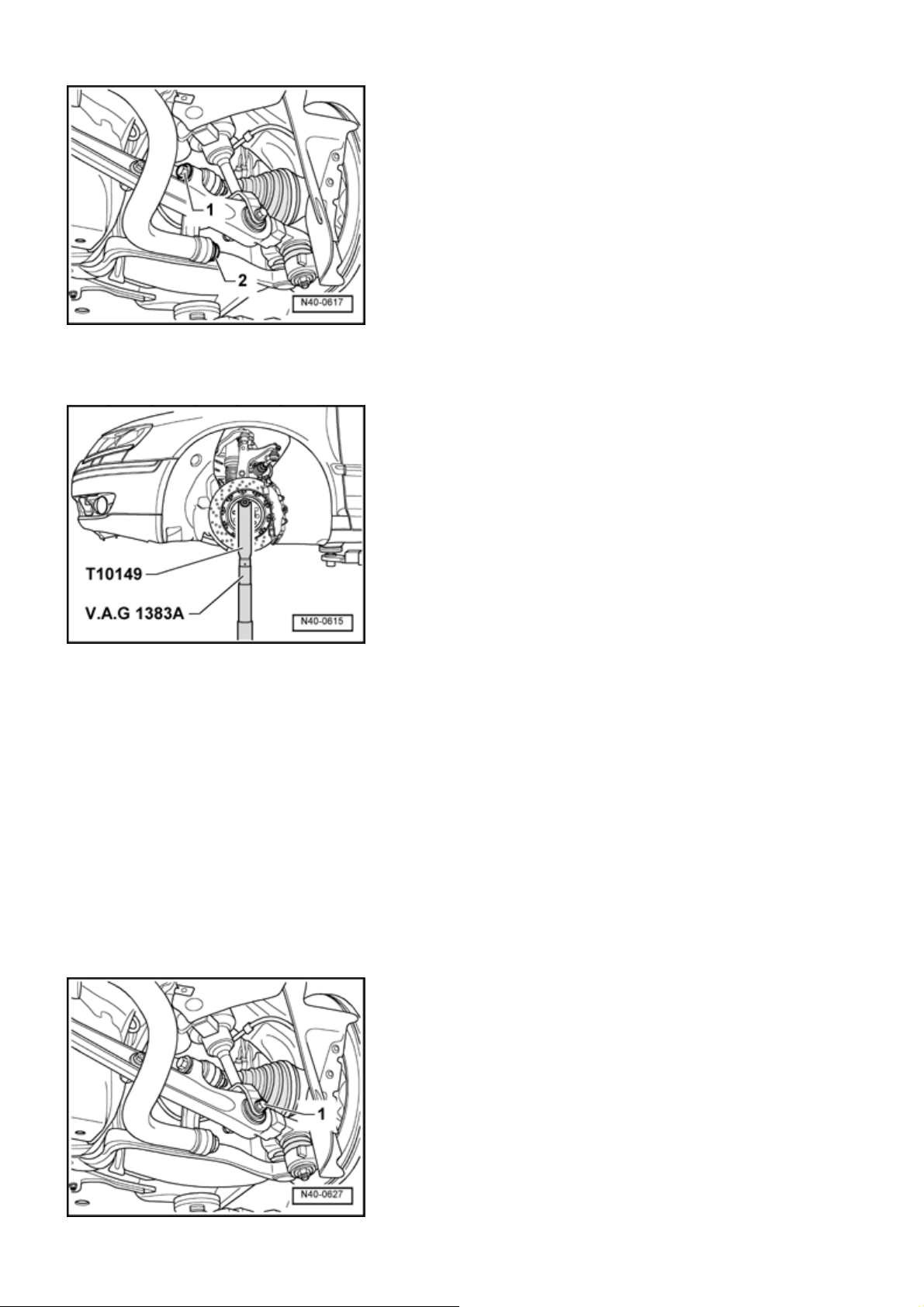
- Loosen connecting link to stabilizer bar
link
- Attach Wheel Hub Support T10149 to wheel hub with a
wheel bolt.
- Raise wheel bearing housing with engine/transmission
ack V.A.G 1383 A and Wheel Hub Support T10149 until
connecting link is "stress free" .
- 1 -
.
and to lower
- 2 -
- Remove connecting link from stabilizer bar.
- Lower wheel bearing housing.
- Move engine/transmission jack V.A.G 1383 A away from
under vehicle.
- Remove both upper links from wheel bearing housing.
Page 14
V
g
Стр. 8 из 29A - Mounting bracket, upper links, air spring strut and wheel bearing housings, assembly over...
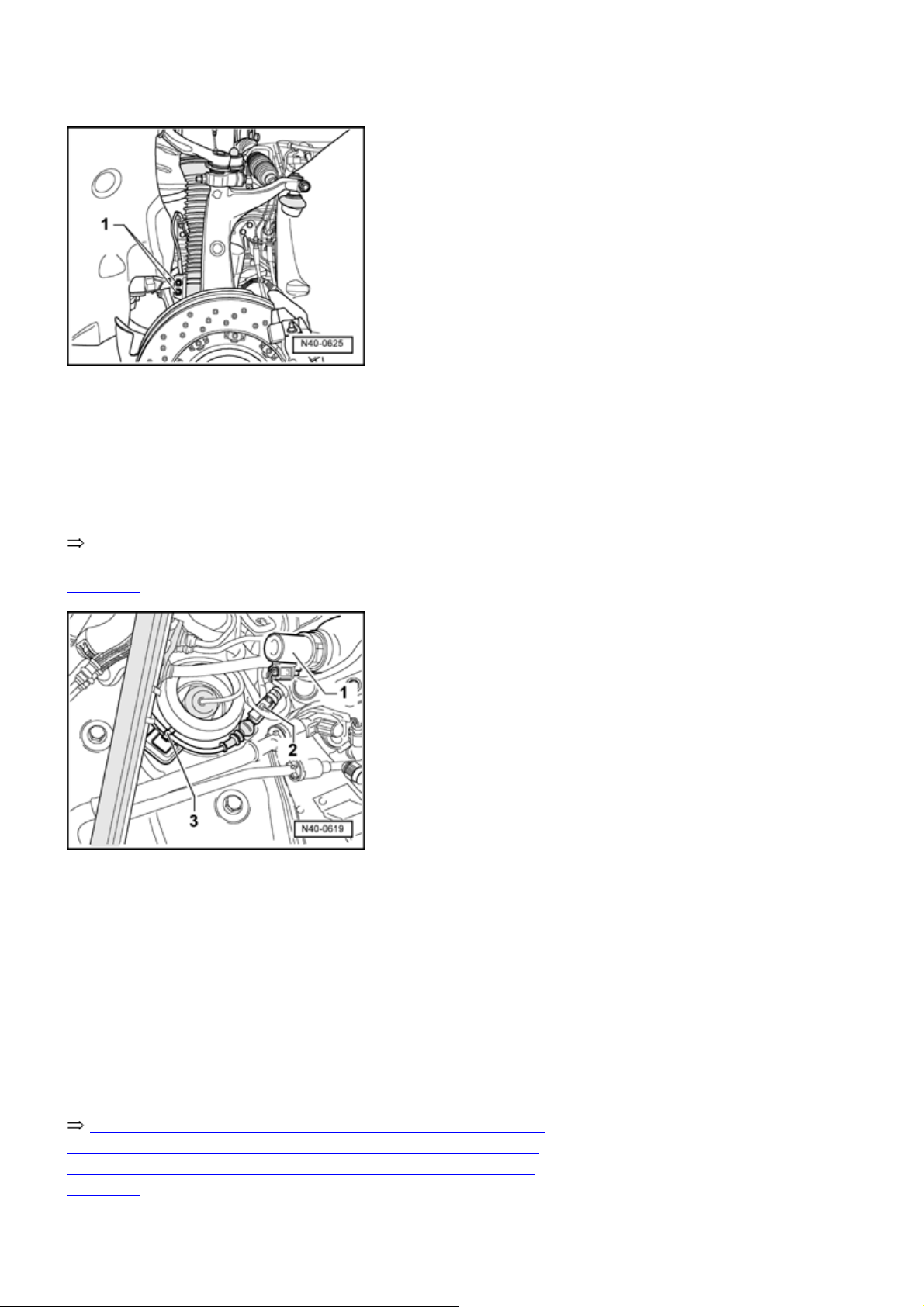
- Remove air spring strut from lower link
- Remove Wheel Acceleration Sensor
strut.
- Remove plenum chamber cover.
Repair Manual, Body Exterior, Repair Group 64,
Stationary windows; Plenum chamber cover, removing and
installing
- 1 -
.
-1-
from air spring
- Unclip cable
- Disconnect strut adjustment switching valve electrical
connector
ehicles with Adaptive Cruise Control
- Remove Brake Booster Membrane Position Sensor G420
.
- 1 -
Repair Manual, Brake System, Repair Group 47, Brake
booster/brake master cylinder, assembly overview; Brake
Booster Membrane Position Sensor G420, removing and
installing
Left side air spring strut, removin
- 2 -
- 3 -
.
.
Page 15
Стр. 9 из 29A - Mounting bracket, upper links, air spring strut and wheel bearing housings, assembly over...
- Turn steering gear left to stop.
Continue removing air spring strut on right side
- Turn steering gear right to stop.
Continue for both sides
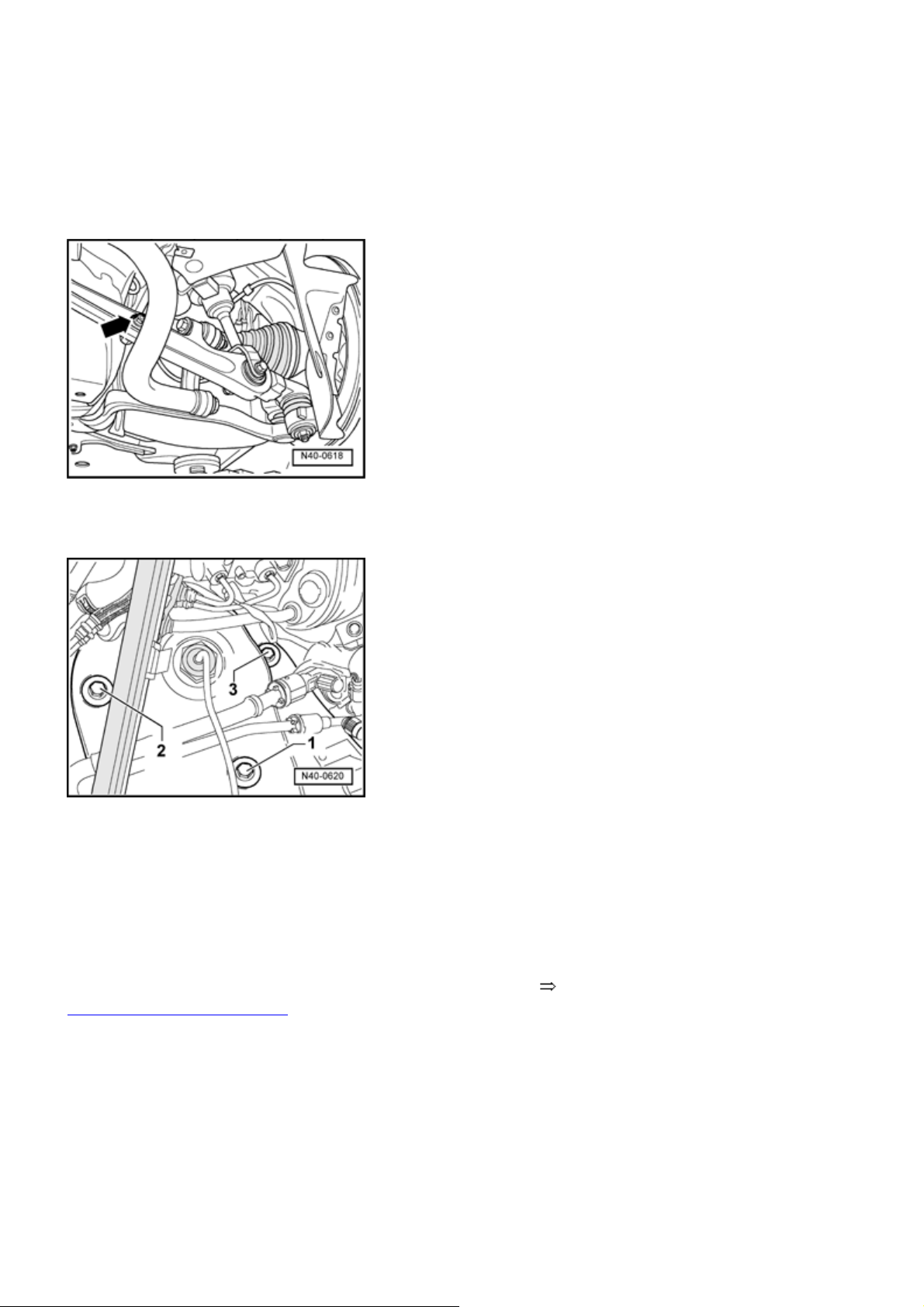
- Remove Level Control System Sensor connecting link
arrow -
from lower link.
-
- Remove air spring strut multi-point socket head bolts
from air spring strut.
2, 3 -
- 1,
- Pull wheel bearing housing as far downward as possible
and then remove from air spring strut.
- Remove mounting bracket from air spring strut.
If air spring strut is to be replaced, first read the following
40
-3, Air spring strut, filling .
Installing
Installation is in reverse order of removal. Note the
following:
- Check threaded bushings (3 pieces, as part of mounting
bracket) are located properly in body.
- Observe tightening sequence for multi-point socket head
bolts.
Page 16
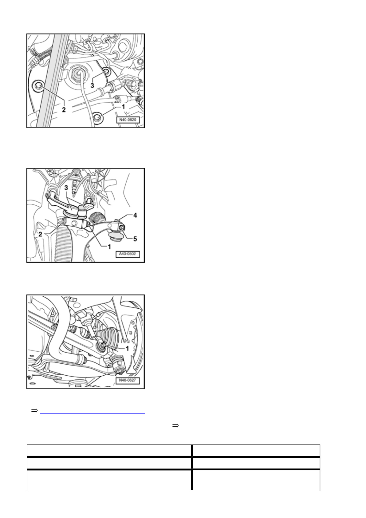
y
Tightening sequence, air spring damper to bod
Стр. 10 из 29A - Mounting bracket, upper links, air spring strut and wheel bearing housings, assembly o...
- Push upper link
tightening.
- Raise wheel bearing housing and then tighten hex bolt
40-2, Lift wheel bearing housing
-
- Check basic setting of level control system Vehicle
Diagnosis, Testing and Information System VAS 5051 .
as far down as possible when
- 3 -
- 1
Tightening torques
Air line to air spring strut 5 Nm
Connecting link to stabilizer bar
90 Nm plus an additional 1 / 4 turn (90
Page 17
1)
g
2)
Стр. 11 из 29A - Mounting bracket, upper links, air spring strut and wheel bearing housings, assembly o...
)
Connecting link to lower link
1)
2)
90 Nm plus an additional 1 / 4 turn (90
)
Upper link to wheel bearing housing 50 Nm
Wheel acceleration sensor to air spring strut 10 Nm
Connecting link from vehicle level sensor to lower
8 Nm
link
Air spring strut to lower link
1)
2)
Mounting bracket to body
1)
90 Nm plus an additional 1 / 4 turn (90
)
50 Nm plus an additional 1 / 4 turn (90
)
Air spring strut to mounting bracket 20 Nm
1)
Use new bolts/nuts
2)
Tighten bolts/nuts in curb weight position
Air spring strut, fillin
Special tools, testers and auxiliary items required
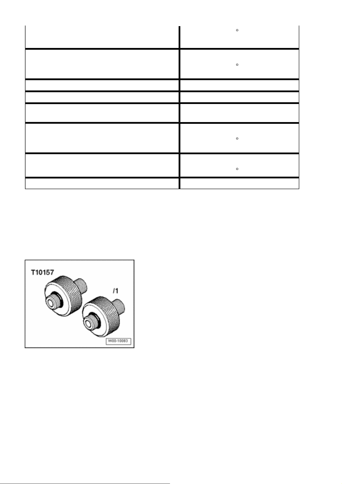
Adapter T10157
Air suspension strut charger VAS 6231 , not depicted
Steel gas cylinder filled with Argon or Corgon, not
illustrated
Note:
Air spring struts are supplied as replacement parts
with a minimum pressure. By sitting in storage for
Page 18
extended periods this minimum pressure can
diminish (just like a tire). Before the air spring strut is
removed from its packaging, this minimum pressure
must be controlled and restored by "refilling" . Without
this necessary refilling, folds can form in the underfilled air spring boot. These folds cause damage
which can lead to premature failure.
- Remove cover from packaging.
Стр. 12 из 29A - Mounting bracket, upper links, air spring strut and wheel bearing housings, assembly o...
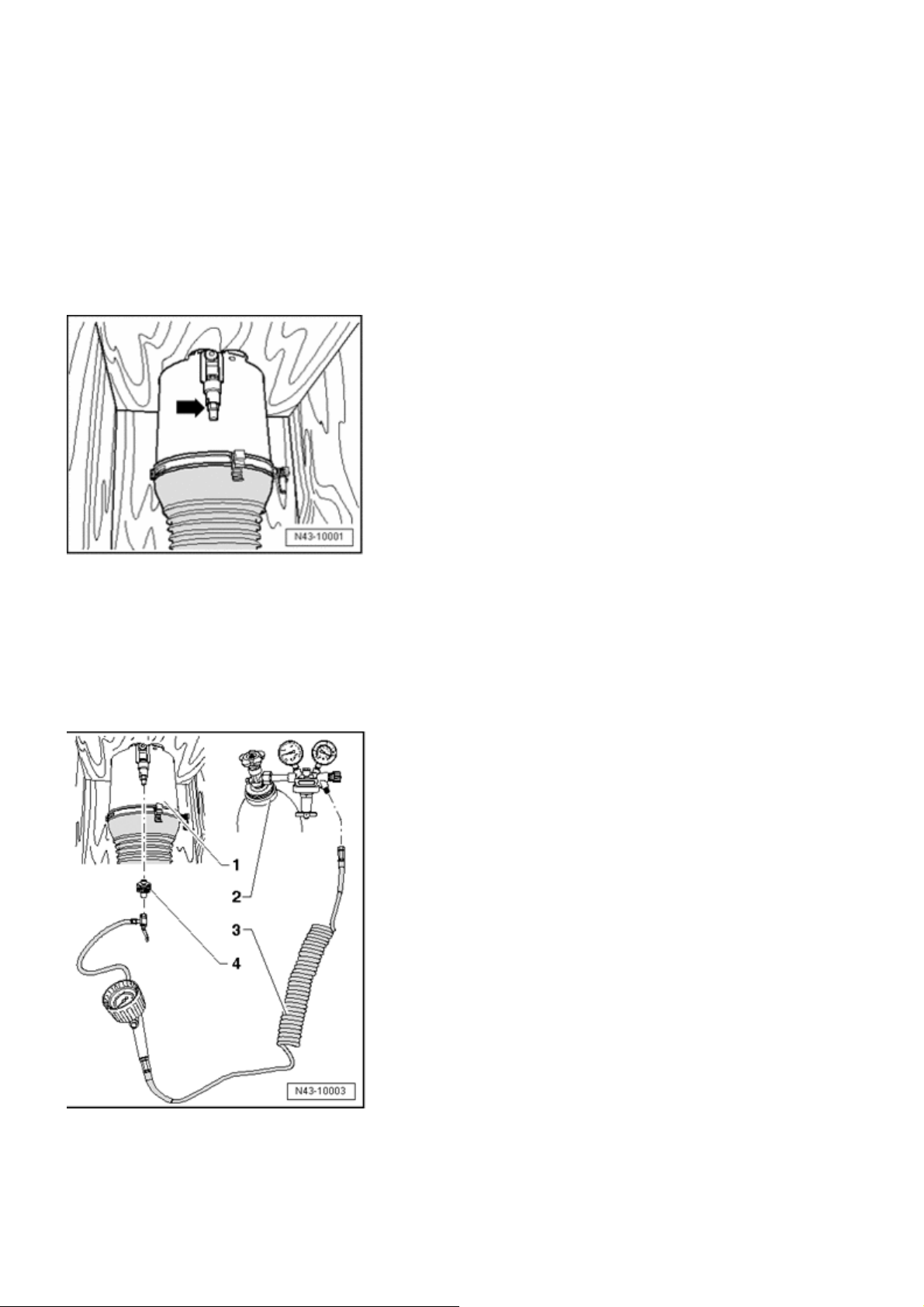
- Remove bolt
- arrow -
from residual pressure retaining
valve.
- Close steel gas bottle pressure valve.
- Become familiar with the relevant rules for prevention of
accidents for pressurized containers and technical gases.
- Connect air spring filler unit VAS 6231 and adapter
T10157 as shown in the illustration.
Air spring strut with packaging
Steel gas bottle for argon, corgon with gauges
Page 19
Air spring filler unit VAS 6231
Adapter T10157
Стр. 13 из 29A - Mounting bracket, upper links, air spring strut and wheel bearing housings, assembly o...
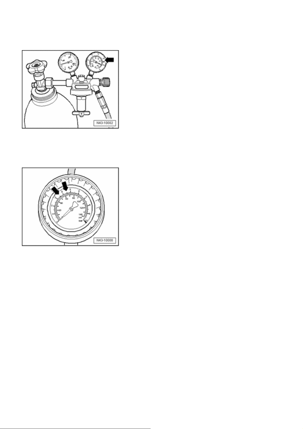
- Set flow rate limiter gauge to 2.0 L/min
-arrow-
.
- Fill gas into air spring strut using several individual
pressure bursts.
The display only shows a correct gas pressure if the
"oscillatory pressure" of the residual pressure retaining
valve is overcome. The "oscillatory pressure" is at approx.
3.5 bar. When the display reaches 3.5 to 4.5 bar, air spring
damper is sufficiently filled with gas.
- Make sure display does not climb over 4.5 bar when
filling.
- Disconnect air spring filler unit VAS 6231 from adapter
T10157 . This dissipates gas above an internal pressure of
3.5 bar.
Minimum pressure is now set. Remove air spring strut from
packaging.
- After installation, first drive the vehicle at high ride height
and then at normal ride height. Repeat this sequence once
more.
Move twice to different ride heights, the gas is replaced
with cleaned air from air supply unit.
Page 20
- Install air spring strut 40-3, Installing .
g
Mounting bracket, removing and installin
Special tools, testers and auxiliary items required
Стр. 14 из 29A - Mounting bracket, upper links, air spring strut and wheel bearing housings, assembly o...
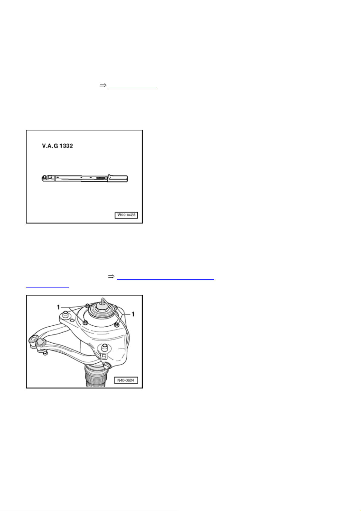
Torque wrench V.A.G 1332
Removing
- Remove air spring strut 40-3, Air spring strut removing
and installing .
- Remove mounting bracket from air spring strut
Installing
Installation is in reverse order of removal.
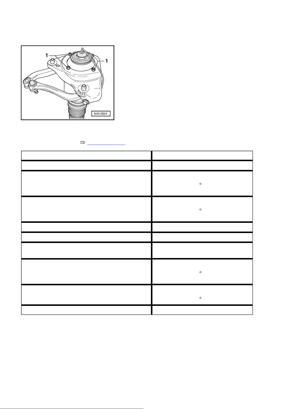
-1-
.
Page 21
Стр. 15 из 29A - Mounting bracket, upper links, air spring strut and wheel bearing housings, assembly o...
- Install mounting bracket to air spring strut
-1-
.
- Install air spring strut 40-3, Installing .
Tightening torque
Air line to air spring strut 5 Nm
Connecting link to stabilizer bar
1)
2)
Connecting link to lower link
1)
2)
90 Nm plus an additional 1 / 4 turn (90
)
90 Nm plus an additional 1 / 4 turn (90
)
Upper link to wheel bearing housing 50 Nm
Wheel acceleration sensor to air spring strut 10 Nm
Connecting link from vehicle level sensor to lower
8 Nm
link
Air spring strut to lower link
1)
2)
90 Nm plus an additional
)
1
/ 4 turn (90
Mounting bracket to body
1)
50 Nm plus an additional 1 / 4 turn (90
)
Air spring strut to mounting bracket 20 Nm
1)
Always use new nuts and bolts
2)
Tighten bolts and nuts in curb weight position
Upper link, removing and installing
Special tools, testers and auxiliary items required
Page 22
Стр. 16 из 29A - Mounting bracket, upper links, air spring strut and wheel bearing housings, assembly o...
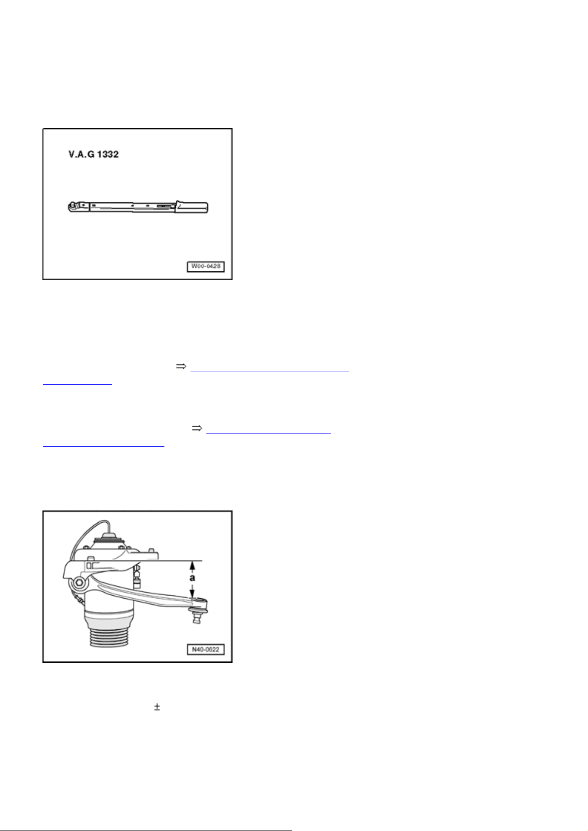
Torque wrench V.A.G 1332
Removing
- Remove air spring strut 40-3, Air spring strut removing
and installing .
- Compress air spring strut in a vise with protective covers.
- Remove mounting bracket 40-3, Mounting bracket,
removing and installing .
- Remove both links from mounting bracket.
Links, setting
- Set upper front link to dimension
Dimension
= 81 2 mm
- a -
and tighten.
- a -
Page 23
Стр. 17 из 29A - Mounting bracket, upper links, air spring strut and wheel bearing housings, assembly o...
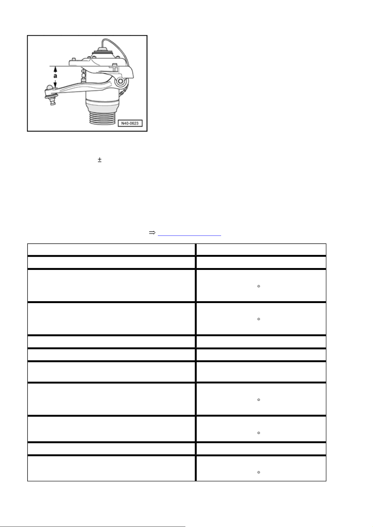
- Set upper rear link to dimension
Dimension
Installing
= 69 2 mm
- a -
and tighten.
- a -
Installation is in reverse order of removal, note the
following:
- Attach both links to mounting bracket.
- Adjust both links before tightening. 40-3, Links, setting
Tightening torque
Air line to air spring strut 5 Nm
Connecting link to stabilizer bar
1)
2)
Connecting link to lower link
1)
2)
90 Nm plus an additional 1 / 4 turn (90
90 Nm plus an additional 1 / 4 turn (90
)
)
Upper link to wheel bearing housing 50 Nm
Wheel acceleration sensor to air spring strut 10 Nm
Connecting link from vehicle level sensor to lower
8 Nm
link
Air spring strut to lower link
1)
2)
Mounting bracket to body
1)
90 Nm plus an additional 1 / 4 turn (90
)
50 Nm plus an additional 1 / 4 turn (90
)
Air spring strut to mounting bracket 20 Nm
Upper link to mounting bracket
1)
1)
Use new bolts and nuts
50 Nm plus an additional 1 / 4 turn (90
)
Page 24
2)
g
p
g
Tighten bolts in curb weight position
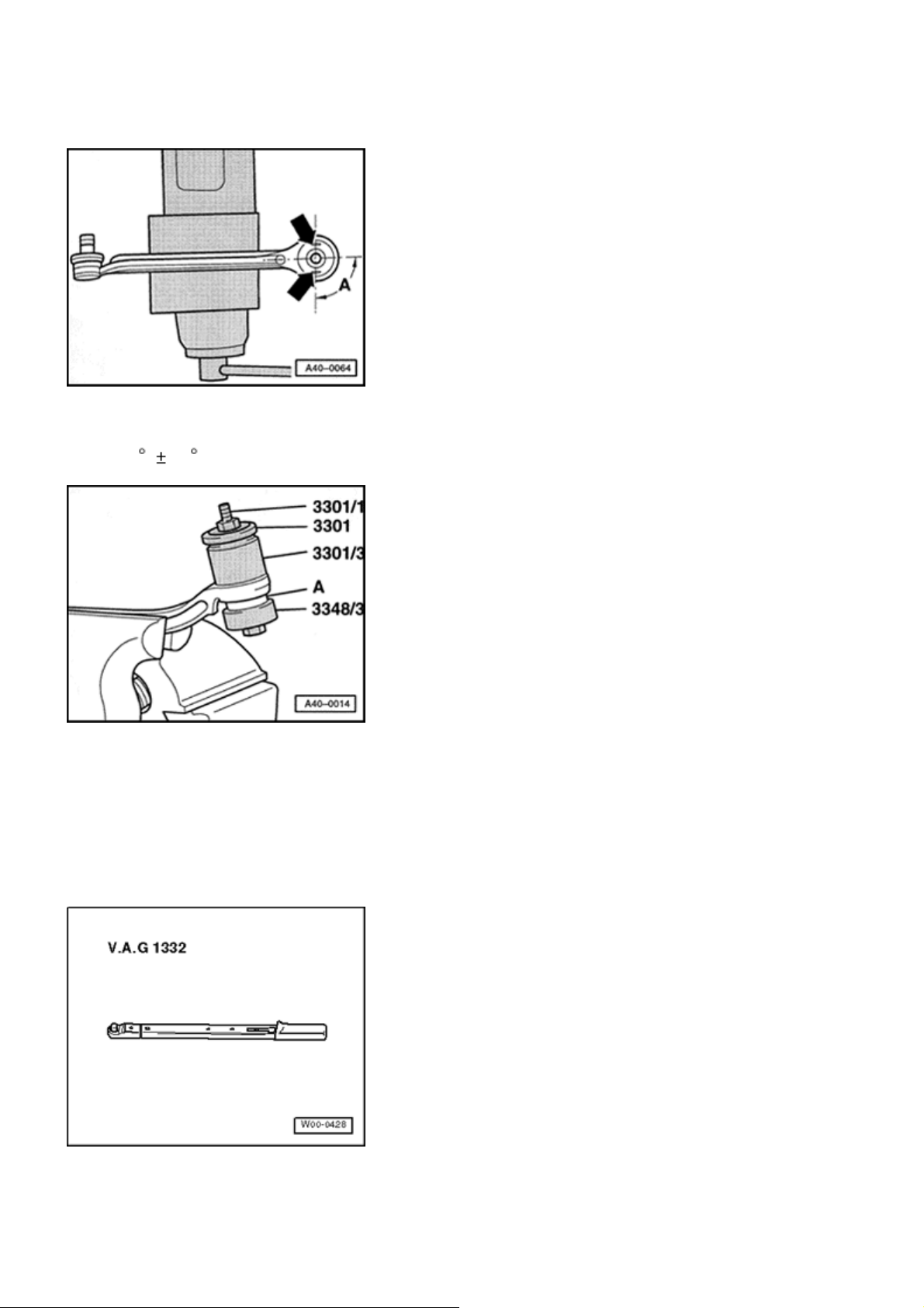
Upper link bonded rubber bushing, replacin
Special tools, testers and auxiliary items required
Стр. 18 из 29A - Mounting bracket, upper links, air spring strut and wheel bearing housings, assembly o...
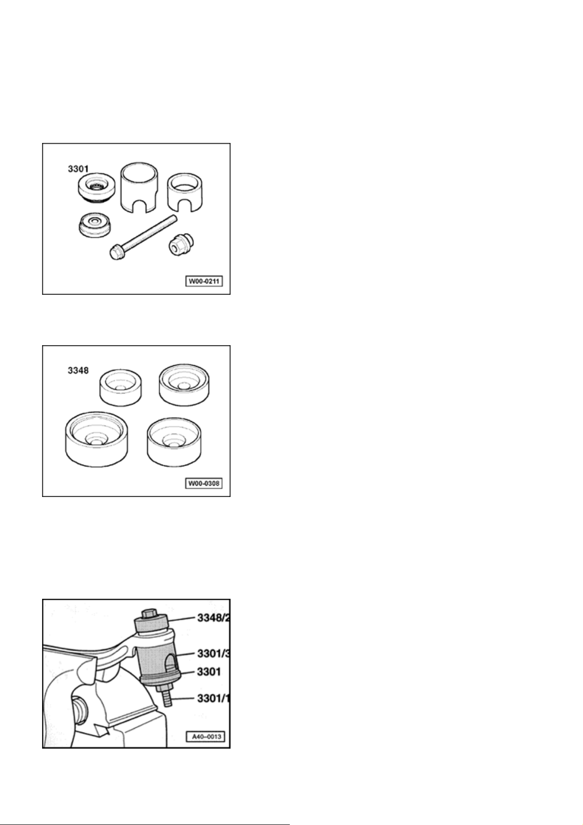
Assembly tool 3301
Front and Rear Bearing Tool 3348
Bonded rubber bushing, removing
Clam
link only in vise with protective covers!
Removing bonded rubber bushin
Page 25
Стр. 19 из 29A - Mounting bracket, upper links, air spring strut and wheel bearing housings, assembly o...
Bonded rubber bushing, seating
Bonded rubber bushing installation location
A =90 5
Seating bonded rubber bushing
Bushing
- A -
Wheel bearing housing, removing and installing
Special tools, testers and auxiliary items required
Torque wrench V.A.G 1332
Page 26
Стр. 20 из 29A - Mounting bracket, upper links, air spring strut and wheel bearing housings, assembly o...
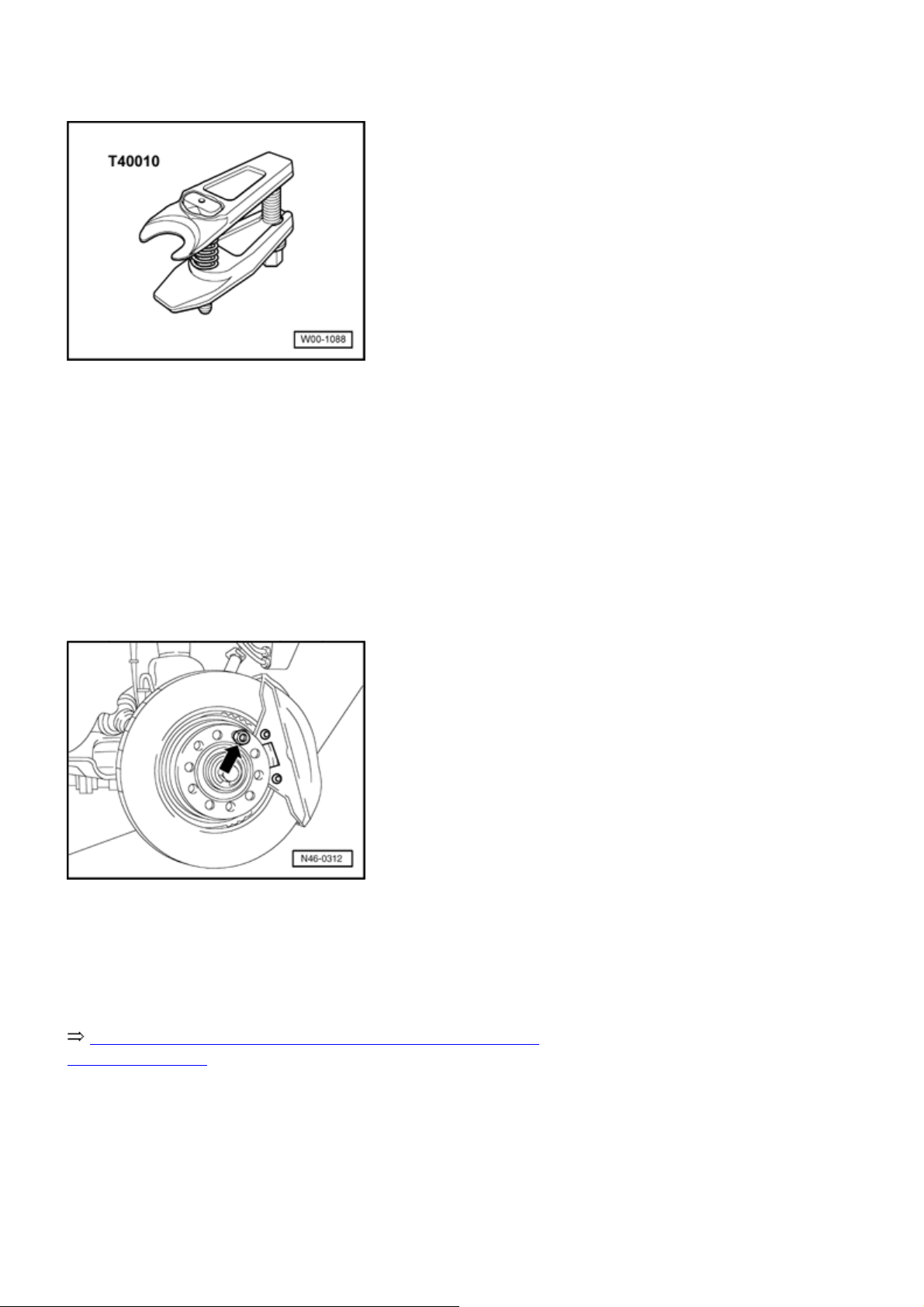
Ball joint puller T40010
Removing
During assembly work, make sure that no indentations
form on boot of air spring strut!
- Remove drive axle hex bolt. Vehicle must be on ground to
do this
- risk of accident -
- Remove front wheel.
.
- Secure brake disc using wheel bolt
- arrow -
.
- Remove brake caliper and disengage from wire to body
Repair Manual, Brake System, Repair Group 46, Front
brakes, servicing
.
- Remove brake disc and cover plate.
- Loosen lower link hex nut and guide link on wheel bearing
housing 2 turns.
Page 27
j
Volkswagen Technical Site: http://volkswagen.msk.ru http://vwts.info http://vwts.ru
огромный архив документации по автомобилям Volkswagen, Skoda, Seat, Audi
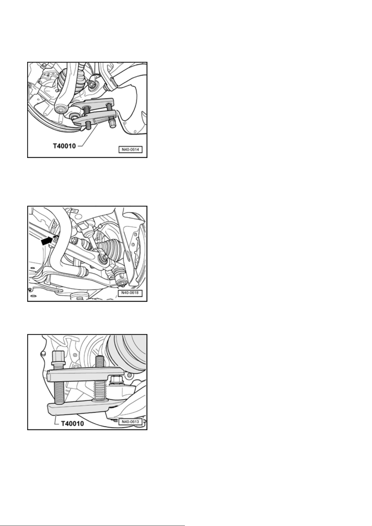
- Press lower link guide pins away from tapered seat using
ball joint puller T40010 .
Стр. 21 из 29A - Mounting bracket, upper links, air spring strut and wheel bearing housings, assembly o...
Do not damage protective joint boot when doing this!
- Remove level control system sensor connecting link from
lower link
- arrow -
.
- Separate guide link guide pin from tapered seat using ball
oin puller T40010 .
Do not damage protective joint boot when doing this!
Page 28
p
Стр. 22 из 29A - Mounting bracket, upper links, air spring strut and wheel bearing housings, assembly o...
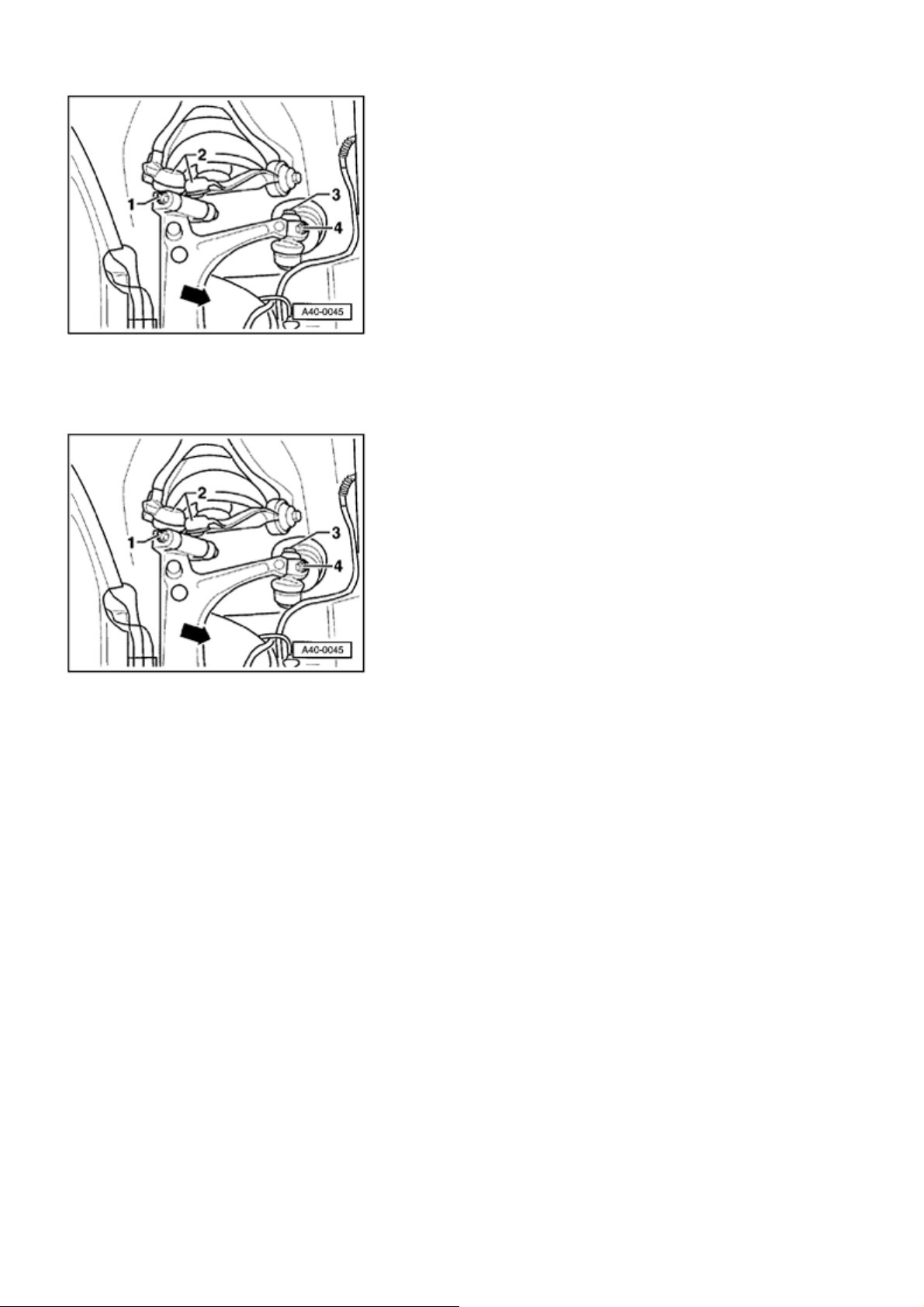
- Remove hex bolt
- Remove tie rod end.
- 3 -
and nut
- 4 -
.
- Remove nut
links
- 2 -
upward.
and remove hex bolt. Then remove both
- 1 -
- Remove lower link and guide link from wheel bearing
housing.
- Remove wheel bearing housing.
Installing
Installation is in reverse order of removal, note the
following:
During assembly work, make sure that no indentations
form on boot of air s
- Insert wheel bearing housing.
ring strut!
- Slide drive axle outer joint into wheel hub and handtighten new hex socket head bolt.
- Insert lower link and guide link guide pins in wheel
bearing housing.
- Insert upper link in wheel bearing housing.
- Press both upper links down as far as possible when
Page 29
Стр. 23 из 29A - Mounting bracket, upper links, air spring strut and wheel bearing housings, assembly o...
tightening!
- Install tie rod.
- Check basic setting of level control system.
- Measure vehicle after installation. 44-3, Wheel
alignment
Tightening torque
Drive axle to wheel hub
1)
.
Brake caliper to wheel bearing housing
200 Nm plus an additional 1 / 2 turn (180 )
Repair Manual, Brake System, Repair Group 46,
Front brakes, servicing
Cover plate to wheel bearing housing 10 Nm
Lower link to wheel bearing housing
1)
120 Nm
Guide link to wheel bearing housing
1)
Connecting link from vehicle level
sensor to lower link
Upper link to mounting bracket
1)
Tie rod to wheel bearing housing
1)
1)
Always use new nuts and bolts
Wheel bearing, assembly overview
120 Nm
8 Nm
50 Nm
50 Nm
Page 30
Стр. 24 из 29A - Mounting bracket, upper links, air spring strut and wheel bearing housings, assembly o...
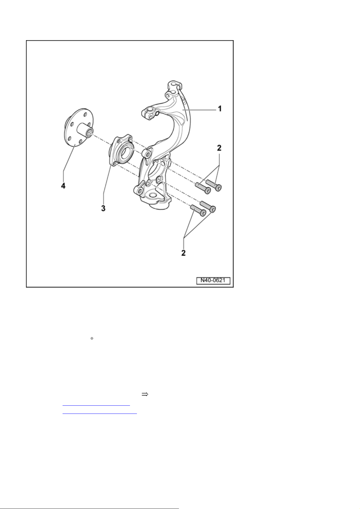
Wheel bearing housing
Multi-point socket head bolt
80 Nm plus an additional
turn (90 )
Always replace
Wheel bearing
Removing and installing
40-3, Wheel bearing,
removing and installing
Installed location:
Larger diameter of wheel
bearing faces wheel hub
1
/ 4
Wheel hub
Page 31
Pressing out 40-3, Wheel
g
bearing, removing and
installing
Pull off bearing inner ring from
hub 40-3, Pressing off
bearing inner ring
Pressing in 40-3, Wheel
bearing, removing and
installing
Wheel bearing, removing and installin
Стр. 25 из 29A - Mounting bracket, upper links, air spring strut and wheel bearing housings, assembly o...
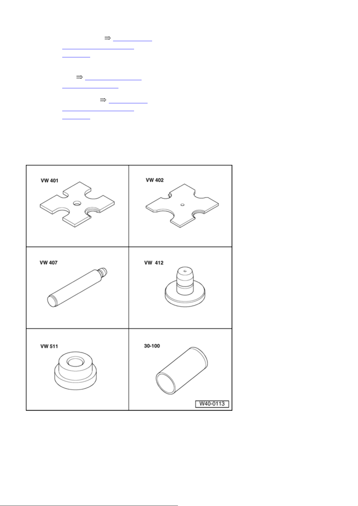
Special tools, testers and auxiliary items
required
Thrust plate VW 401
Thrust plate VW 402
Page 32
p
Стр. 26 из 29A - Mounting bracket, upper links, air spring strut and wheel bearing housings, assembly o...
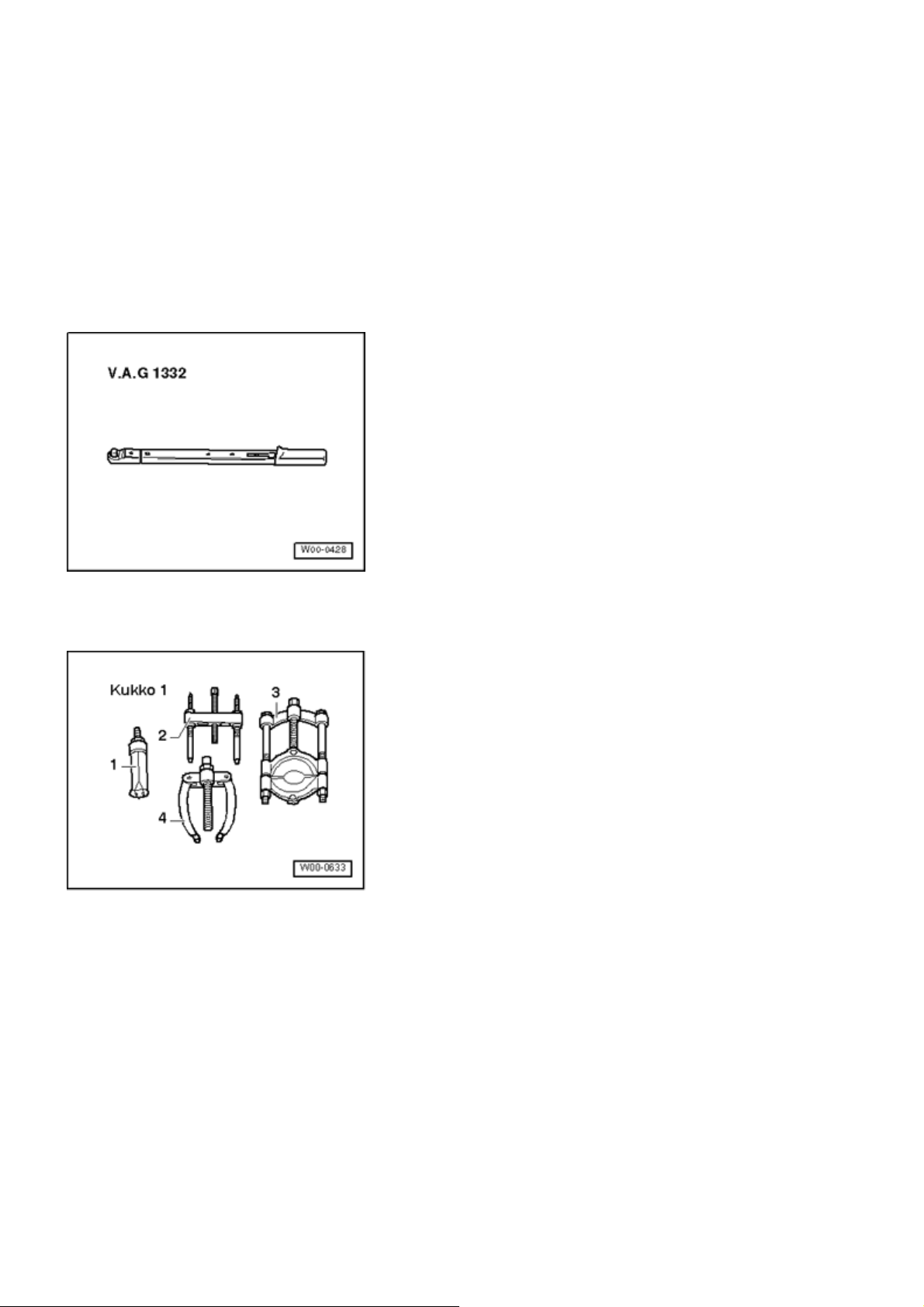
Punch VW 407
Punch VW 412
Thrust pad VW 512
Special tools, testers and auxiliary items required
Torque wrench V.A.G 1332
3 - Separating tool Kukko 17/2
Removing
During assembly work, make sure that no indentations
form on boot of air s
- Remove drive axle hex bolt.
ring strut!
Note:
Only loosen when vehicle is resting on the wheels
danger of accident -
-
Page 33
Стр. 27 из 29A - Mounting bracket, upper links, air spring strut and wheel bearing housings, assembly o...
- Remove front wheel.
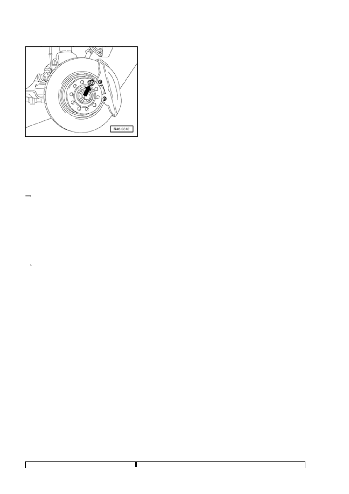
- Secure brake disc using a wheel bolt
-arrow-
.
- Remove brake caliper and tie to body using wire.
Repair Manual, Brake System, Repair Group 46, Front
brakes, servicing
.
- Remove ABS speed sensor
Repair Manual, Brake System, Repair Group 46, Front
brakes, servicing
.
- Remove brake disc and cover plate.
- Press drive axle as far out of wheel hub as possible (in
direction of final drive).
- Turn steering gear toward right.
- Remove wheel bearing unit from wheel bearing housing.
Installing
Installation is in reverse order of removal, note the
following:
During assembly work, make sure that no indentations
form on boot of air spring strut!
- Insert wheel bearing unit and tighten.
- Press upper links down as far as possible when
tightening!
Page 34
Tightening torque
Стр. 28 из 29A - Mounting bracket, upper links, air spring strut and wheel bearing housings, assembly o...
Drive shaft to wheel hub
1)
.
Brake caliper to wheel bearing
housing
200 Nm plus an additional 1 / 2 turn (180 )
Repair Manual, Brake System, Repair Group 46, Front
brakes, servicing
Cover plate to wheel bearing housing 10 Nm
Wheel bearing unit to wheel bearing
80 Nm plus an additional 1 / 4 turn (90 )
housing 1)
1)
Always use new nuts and bolts
Pressing out hub
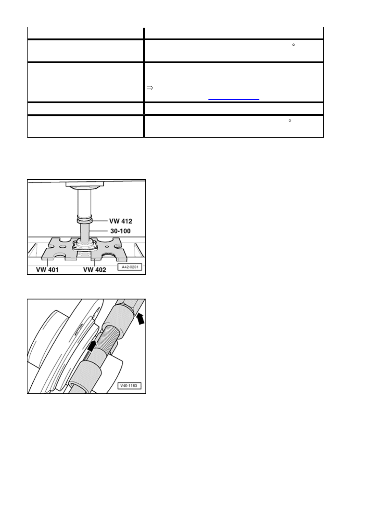
- Press out wheel hub.
- Insert separating tool in bearing inner race ring groove
arrow -
and hub and tension threaded spindle.
Note:
Use a commercially available separating tool , such
as Kukko 17/2.
-
- Press bearing inner race off wheel hub.
Page 35
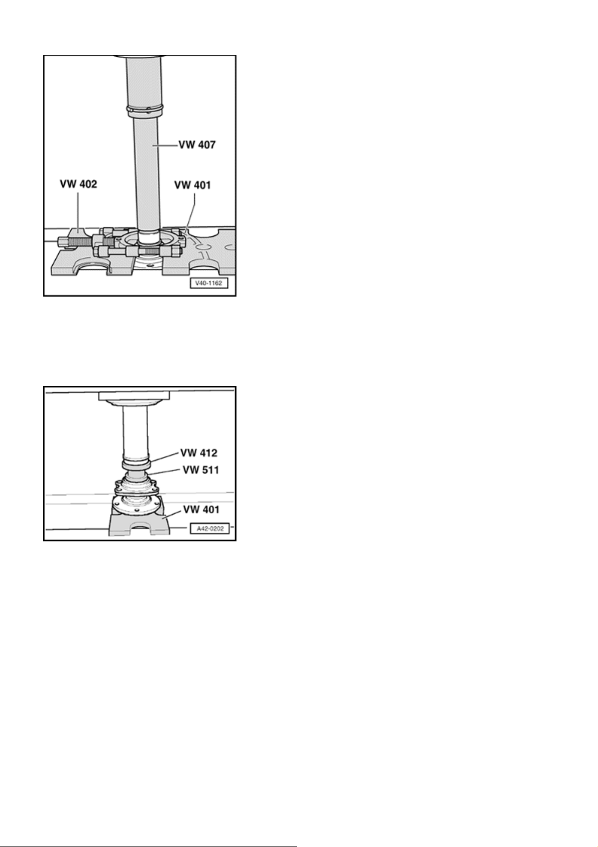
g
Стр. 29 из 29A - Mounting bracket, upper links, air spring strut and wheel bearing housings, assembly o...
Pressing off bearing inner rin
Pressing in wheel hub
- Press wheel hub into wheel bearing to stop.
Page 36
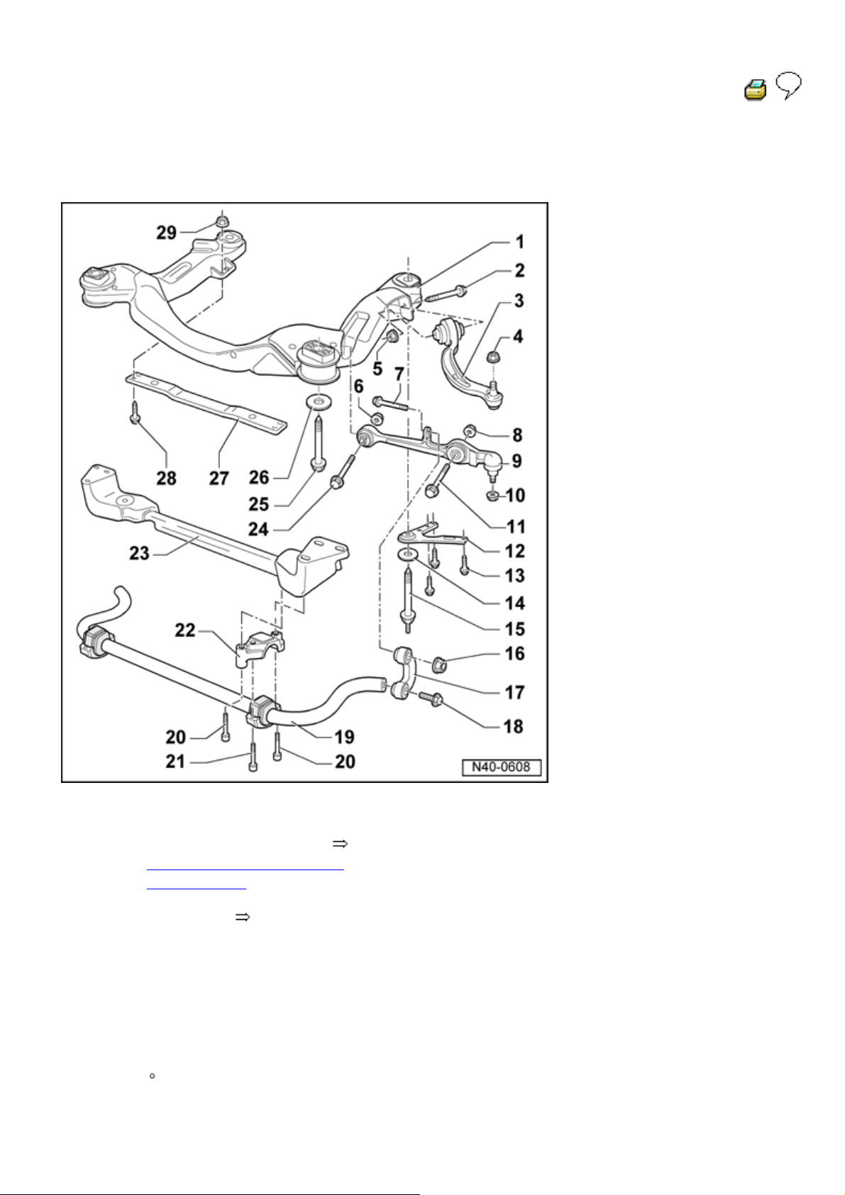
B - Subframe, lower link, and stabilizer bar,
y
assembl
overview
Стр. 1 из 17B - Subframe, lower link, and stabilizer bar, assembly overview
40 - 4
Subframe
Removing and installing
Application See Parts
Hex bolt
M 12 x 1.5 x 120
70 Nm plus an additional 180
Always replace
40-4, Subframe, removing
and installing
Catalog
( 1 / 2 turn)
Page 37
Guide link
Removing and installing
Hex nut
120 Nm
Always replace
Hex nut
Стр. 2 из 17B - Subframe, lower link, and stabilizer bar, assembly overview
40-4, Guide link, removing
and installing
Self-locking
Self-locking
Always replace
Hex nut
70 Nm plus an additional 180
Lift wheel bearing housing
Self-locking
Always replace
Hex bolt
Lift wheel bearing housing
before fastening 40-2, Lift
wheel bearing housing
( 1 / 2 turn)
before fastening 40
-2, Lift
wheel bearing housing
Hex nut
M 12 x 1.5 x 70
Lift wheel bearing housing
before fastening 40-2, Lift
wheel bearing housing
Always replace
90 Nm plus an additional 90
( 1 / 4 turn)
Page 38
Self-locking
Always replace
Lower link
Removing and installing
40-4, Lower link, removing
and installing
Hex nut
120 Nm
Self-locking
Always replace
Стр. 3 из 17B - Subframe, lower link, and stabilizer bar, assembly overview
Hex head bolt
M 12 x 1.5 x 85
Lift wheel bearing housing
before fastening 40-2, Lift
wheel bearing housing
Always replace
Subframe support plate
Hex bolt
M10 x 25
40 Nm plus an additional 90
( 1 / 4 turn)
Always replace
Washer
Hex bolt
130 Nm plus an additional 90
Always replace
Hex nut
M14 x 1.5 x 90
( 1 / 4 turn)
Page 39
90 Nm plus an additional 90
( 1 / 4 turn)
Self-locking
Always replace
Connecting link
Left and right connecting links
are identical
Стр. 4 из 17B - Subframe, lower link, and stabilizer bar, assembly overview
Installed location
40-4,
Installed location of connecting
link
Arrow on connecting link points
in direction of travel
Larger diameter of connecting
link is at stabilizer bar and lower
link
Hex bolt
M 12 x 1.5 x 65
90 Nm plus an additional 90
( 1 / 4 turn)
Lift wheel bearing housing
before fastening 40-2, Lift
wheel bearing housing
Always replace
Stabilizer bar
Removing and installing
40-4, Stabilizer bar, removing
and installing
Multi-point socket head bolt
50 Nm
Multi-point socket head bolt
50 Nm
Mounting bracket
Page 40

g
Engine carrier
Repair Manual, Engine Mechanical,
Fuel Injection Ignition, Repair Group 10,
Engine, removing and installing
Hex bolt
M 12 x 1.5 x 95
Стр. 5 из 17B - Subframe, lower link, and stabilizer bar, assembly overview
Always replace
Hex bolt
M14 x 1.5 x 135
130 Nm plus an additional 90
( 1 / 4 turn)
Always replace
Washer
Subframe support
Hex bolt
M10 × 40
50 Nm plus an additional 90
1
(
/ 4 turn)
Self-locking hex nut
Always replace
Subframe, removing and installin
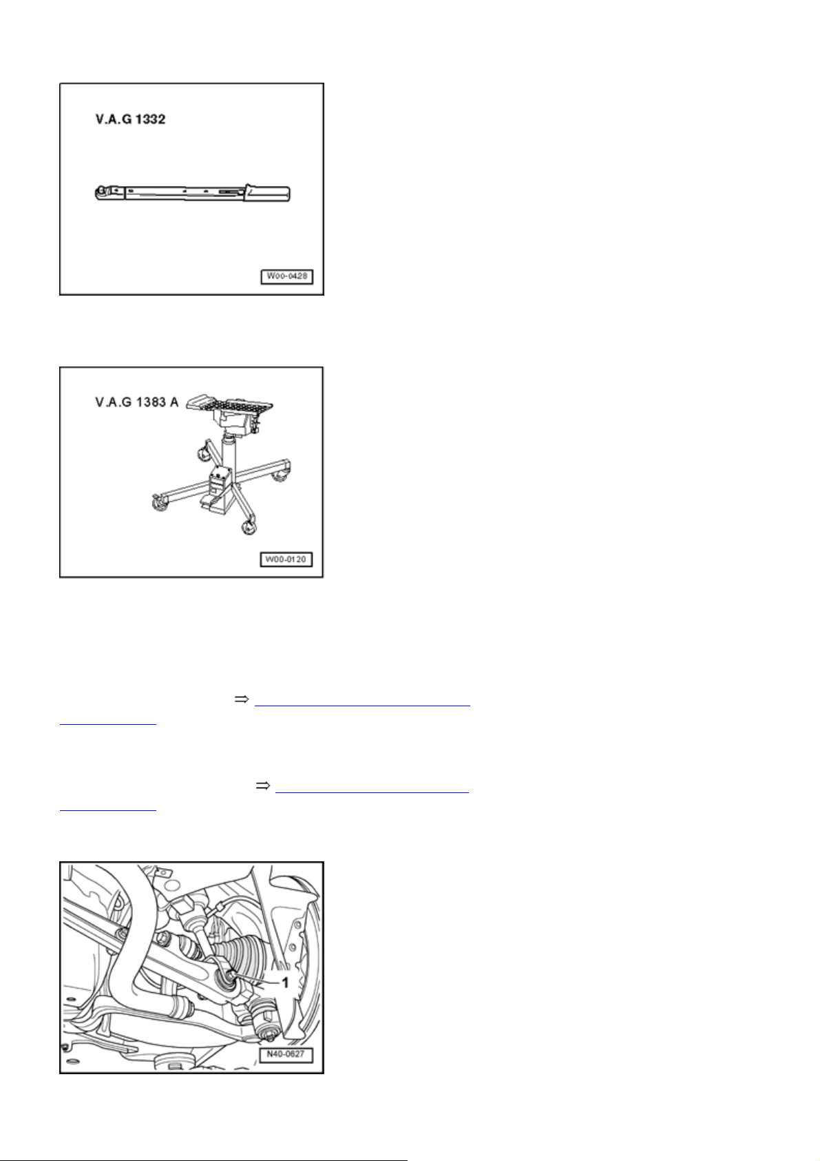
Special tools, testers and auxiliary items required
Page 41
Стр. 6 из 17B - Subframe, lower link, and stabilizer bar, assembly overview
Torque wrench V.A.G 1332
Engine/transmission jack V.A.G 1383 A
Removing
- Remove stabilizer bar 40-4, Stabilizer bar, removing
and installing .
- Remove front wheels.
- Remove both guide links 40-4, Guide link, removing
and installing .
- Loosen both lower links at subframe.
Page 42
Стр. 7 из 17B - Subframe, lower link, and stabilizer bar, assembly overview
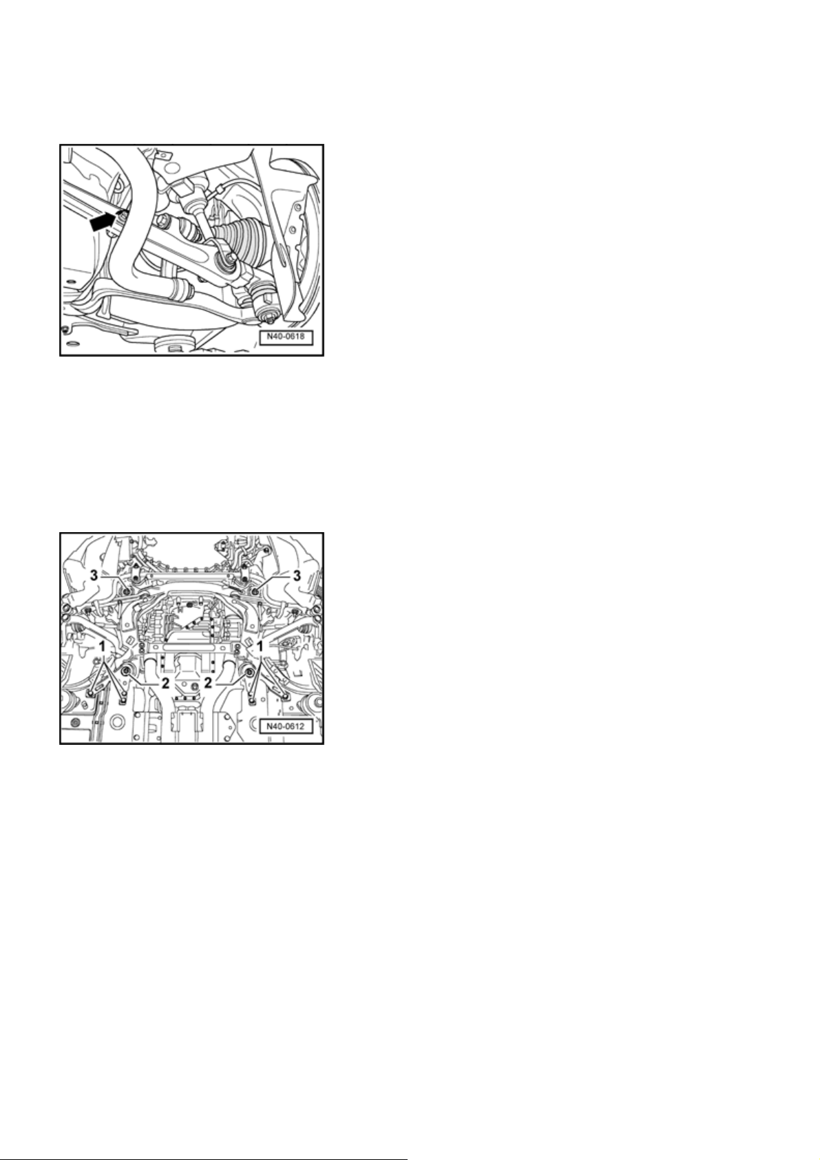
- Loosen hex bolt
but do not remove.
- 1 -
- Disconnect all electrical wires from body to front axle.
- Remove connecting link
- arrow -
from level control
system sensor to lower link.
- Mark installation position of subframe to body with felt-tip
pen.
- Support subframe with engine/transmission jack V.A.G
1383 A and universal mount.
- Remove hex bolts
- 1, 2 -
and
in sequence shown.
- 3 -
- Lower subframe as far as possible and then remove both
lower links from subframe.
- Slowly lower subframe and remove.
Installing
Installation is in reverse order of removal, note the
following:
- When installing subframe, align with help of markings on
body.
- Install subframe with old hex bolts. Replace with new
ones after vehicle alignment.
- When doing so, tighten hex bolts to specified tightening
Page 43
g
Стр. 8 из 17B - Subframe, lower link, and stabilizer bar, assembly overview
torque without additional tightening.
- Place vehicle on wheels or raise wheel bearing housing to
tighten lower link and guide link 40-2, Lift wheel bearing
housing
- Check basic setting of self-levelling suspension.
- Measure vehicle after installation 44-3, Wheel
alignment .
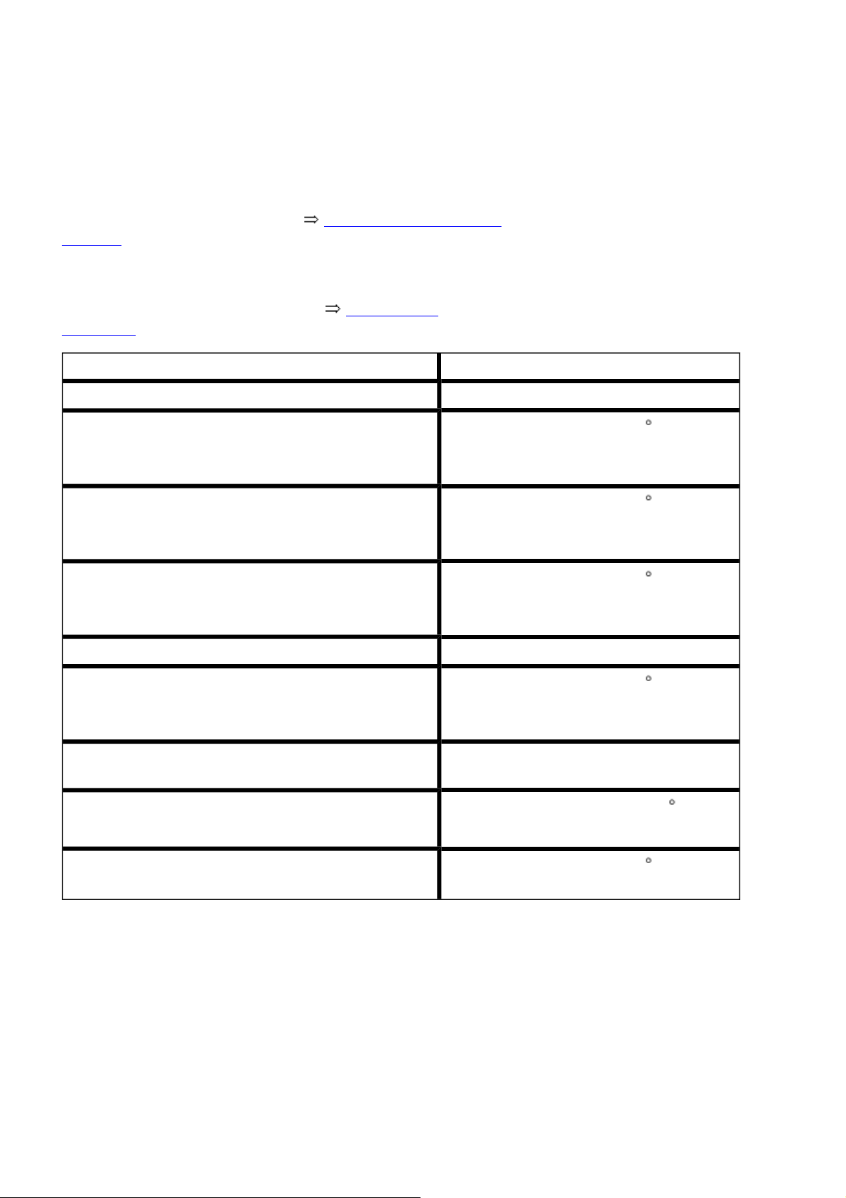
Tightening torque
Stabilizer bar to engine carrier 50 Nm
Connecting link to stabilizer bar
1)
2)
Connecting link to lower link
1)
2)
Guide link to subframe
1)
2)
90 Nm plus an additional 90 ( 1 / 4 turn)
90 Nm plus an additional 90 ( 1 / 4 turn)
70 Nm plus an additional 90 ( 1 / 4 turn)
Guide link to wheel bearing housing 120 Nm
Air spring strut to lower link
1)
2)
Connecting link from vehicle level sensor to lower
90 Nm plus an additional 90 ( 1 / 4 turn)
8 Nm
link
Subframe to body, bolts M14
1)
Subframe to body, bolts M10
1)
1)
Always use new nuts and bolts
2)
Tighten screws and nuts in curb weight position
Stabilizer bar, removing and installin
130 Nm plus an additional 90 ( 1 / 4
turn)
40 Nm plus an additional 90 ( 1 / 4 turn)
Special tools, testers and auxiliary items required
Page 44
Стр. 9 из 17B - Subframe, lower link, and stabilizer bar, assembly overview
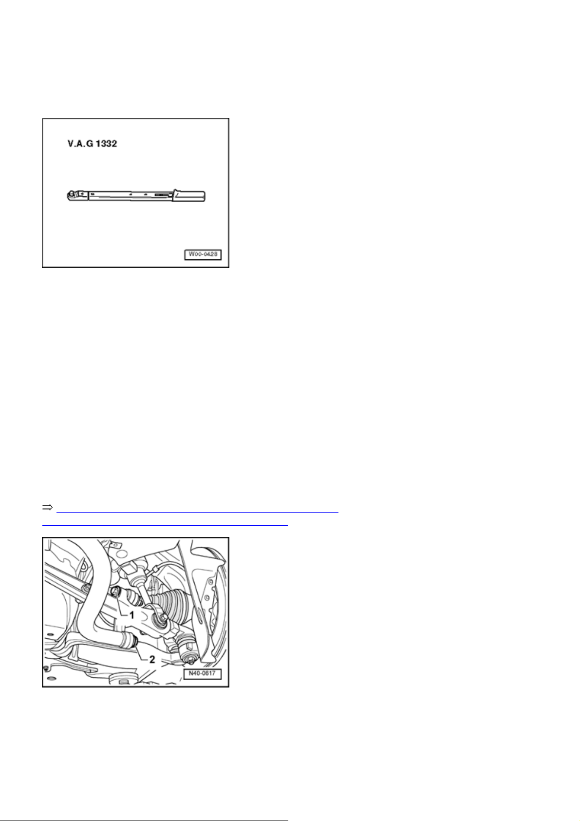
Torque wrench V.A.G 1332
Removing
Note:
Vehicle must rest on wheels for removal and
installation of stabilizer bar. Otherwise, ther e is a risk
that the stabilizer bar or other components may be
damaged.
- Remove front and rear noise insulation.
Repair Manual, Body Exterior, Repair Group 50, Noise
insulation; noise insulation - assembly overview
- Loosen hex bolt
and remove hex bolt
- 1 -
.
-2-
Page 45
Стр. 10 из 17B - Subframe, lower link, and stabilizer bar, assembly overview
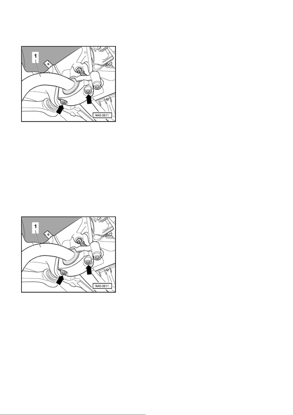
- Loosen stabilizer bar
on both sides.
- 1 -
- Align stabilizer bar so that the multi-point socket head
bolts
- arrows -
- Remove stabilizer bar.
Installing
can be turned easily by hand.
Installation is in reverse order of removal, note the
following:
- Insert stabilizer bar.
- Install multi-point socket head bolts
- arrows -
by hand on
both sides.
- Align stabilizer bar
so that the multi-point socket head
- 1 -
bolts can be turned by hand easily.
- Alternately tighten multi-point socket head bolts to
stabilizer bar mounting bracket.
- Attach stabilizer bar to connecting link.
- Tighten connecting links.
Page 46
k
Стр. 11 из 17B - Subframe, lower link, and stabilizer bar, assembly overview
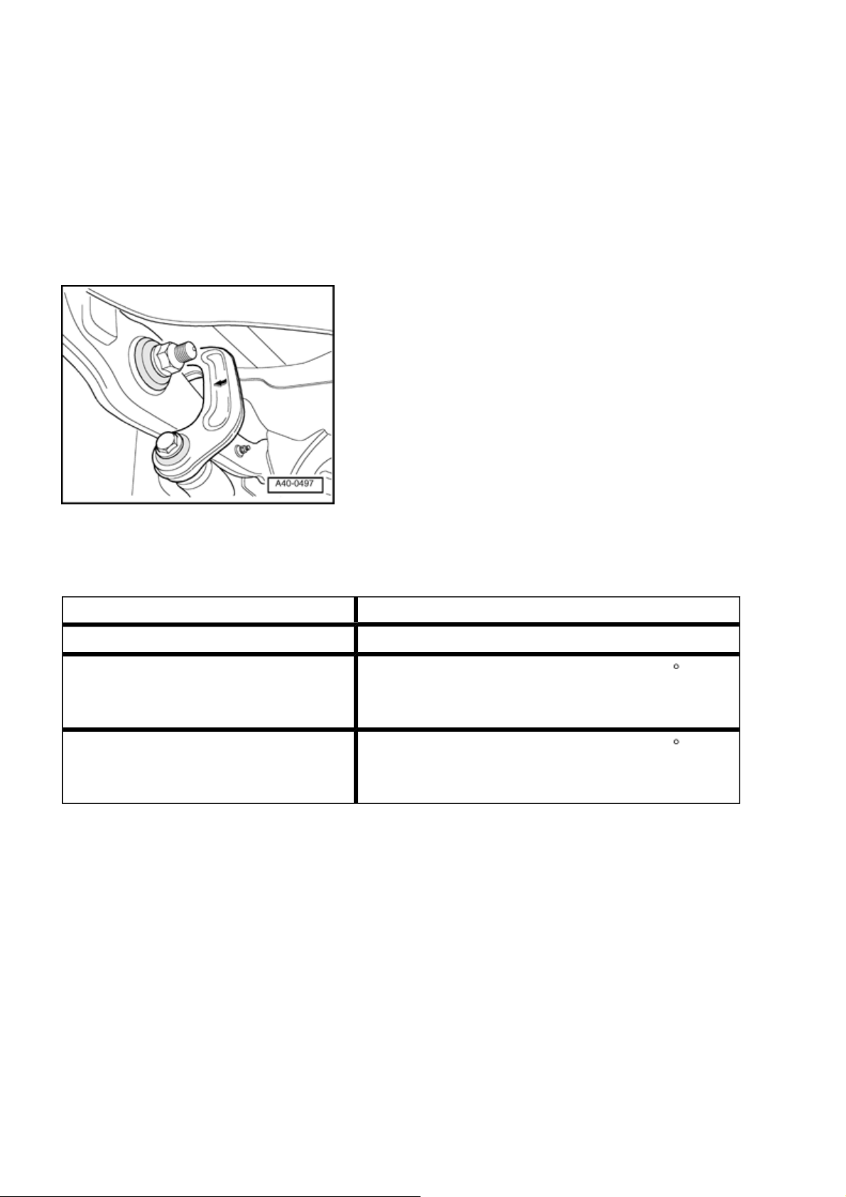
Installed location of connecting lin
Tightening torque
Stabilizer bar to engine carrier 50 Nm
Connecting link to stabilizer bar
1)
2)
Connecting link to lower link
1)
2)
1)
Always use new nuts and bolts
2)
Tighten bolts and nuts in curb weight position
90 Nm plus an additional 1 / 4 turn (90 )
90 Nm plus an additional
1
/ 4 turn (90 )
Lower link, removing and installing
Page 47
Стр. 12 из 17B - Subframe, lower link, and stabilizer bar, assembly overview
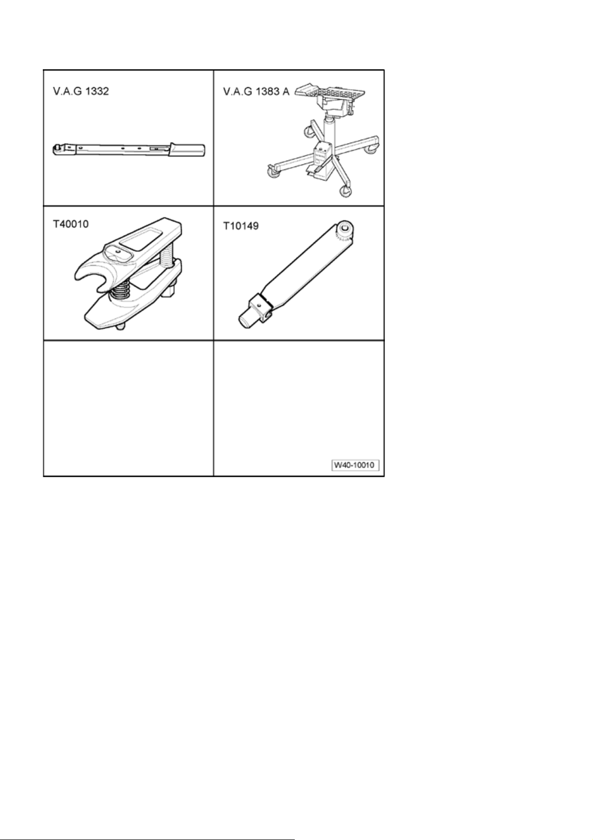
Special tools, testers and auxiliary items
required
Torque wrench V.A.G 1332
Engine/transmission jack V.A.G
1383 A
Wheel hub support T10149
Ball joint puller T40010
Removing
- Remove hex bolt for drive axle. (Only loosen when vehicle
is resting on the wheels
-danger of accident -
).
- Remove front wheel.
Page 48
Стр. 13 из 17B - Subframe, lower link, and stabilizer bar, assembly overview
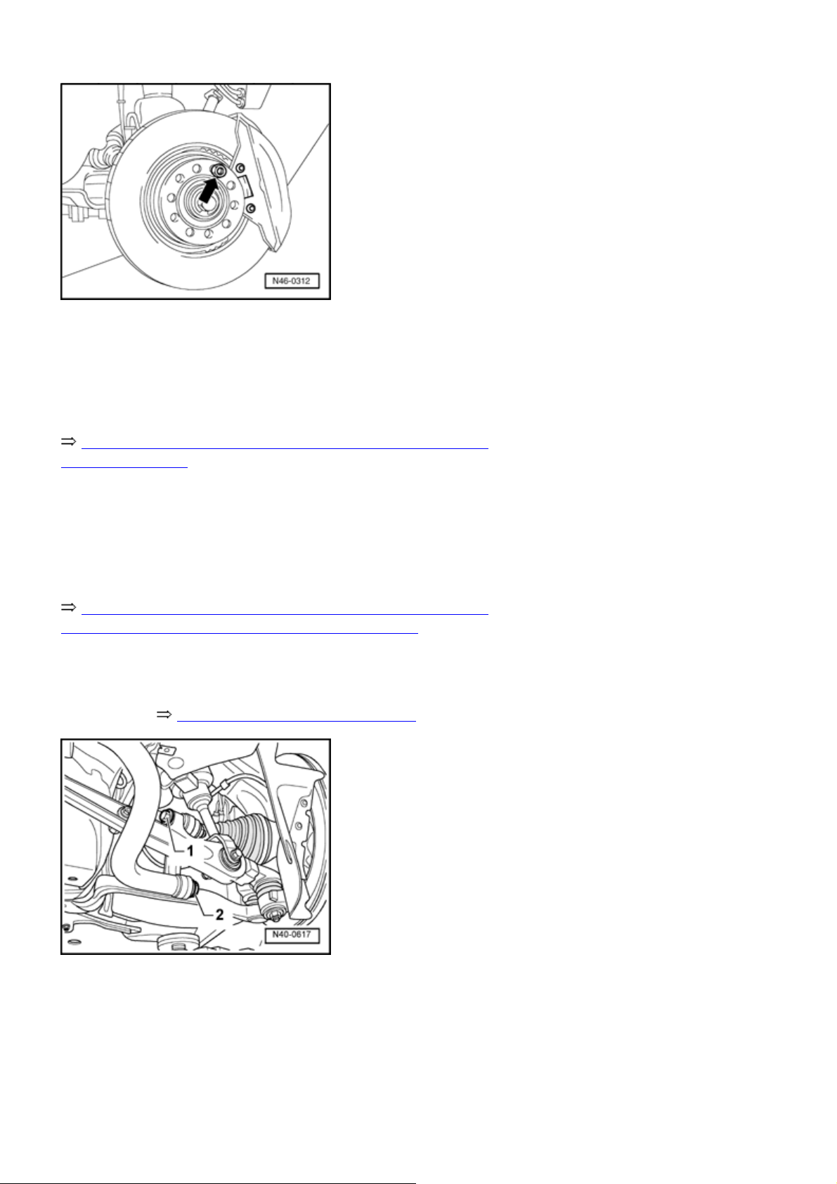
- Secure brake disk using a wheel bolt
- Remove brake caliper and tie to body using wire.
Repair Manual, Brake System, Repair Group 46, Front
brakes, servicing
- Remove brake disc and cover plate.
- Remove front and rear noise insulation
Repair Manual, Body Exterior, Repair Group 50, Noise
insulation; Noise insulation - assembly overview
.
- Raise wheel bearing housing until connecting link is
"stress free" 40-2, Lift wheel bearing housing
-arrow-
.
- Loosen connecting link at stabilizer bar
link
- Remove connecting link from stabilizer bar.
- Lower wheel bearing housing.
- Move engine/transmission jack away from under the
- 1 -
.
and to lower
- 2 -
Page 49
vehicle.
ge p
- Remove both upper links from wheel bearing housing.
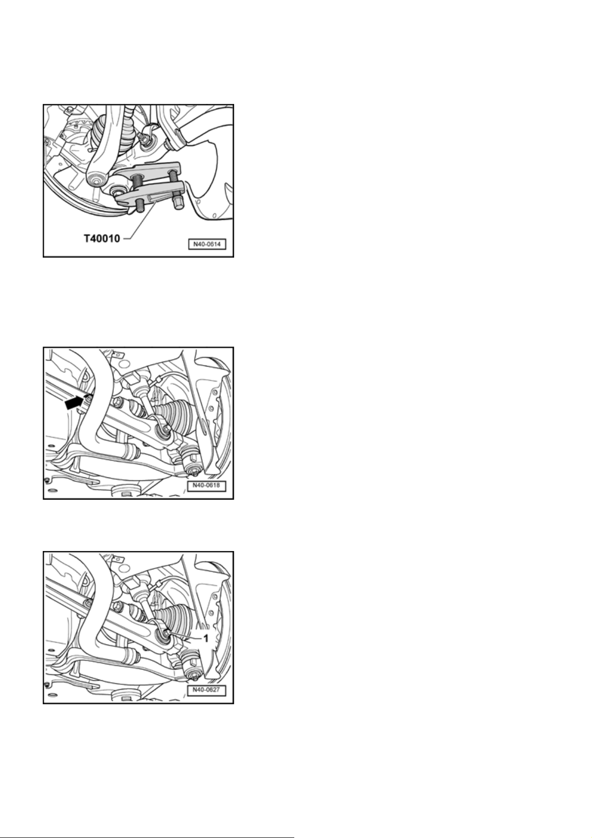
- Remove hex bolt from lower link guide pin. Then press
guide pin away from tapered seat with ball join puller
T40010 .
Стр. 14 из 17B - Subframe, lower link, and stabilizer bar, assembly overview
Do not dama
- Remove Level Control System Sensor connecting link
arrow -
from lower link.
rotective joint boot when doing this!
-
- Remove air spring strut
- Turn steering gear toward right.
- Pull wheel bearing housing down as far as possible and
swing lower link out of air spring strut fork.
from lower link.
-1 -
Page 50
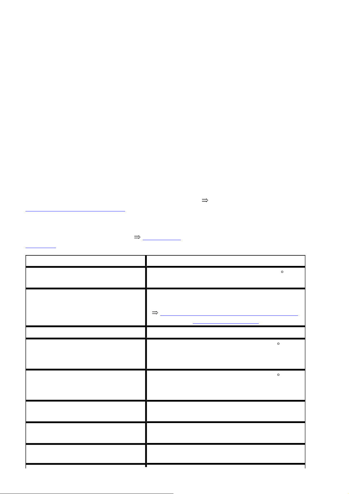
Стр. 15 из 17B - Subframe, lower link, and stabilizer bar, assembly overview
- Remove lower link from subframe.
- Mark installation position of subframe to body using a felttip pen.
- Lower subframe to remove hex bolt.
- Remove lower link.
Installing
Installation is in reverse order of removal, note the
following:
- Align subframe with help of markings on body.
- Tighten subframe with bolts originally installed. Replace
these with new bolts after vehicle alignment.
- Tighten bolts originally installed to specified torque
without additional tightening.
- Raise wheel bearing housing for fastening to subframe
40-2, Lift wheel bearing housing
- Check basic setting of level control system.
- Measure vehicle after installation 44-3, Wheel
alignment .
Tightening torque
Drive shaft to wheel hub
1)
.
Brake caliper to wheel bearing housing
200 Nm plus an additional 1 / 2 turn (180 )
Repair Manual, Brake System, Repair Group 46,
Front brakes, servicing
Cover plate to wheel bearing housing 10 Nm
Connecting link to stabilizer bar
1)
2)
Connecting link to lower link
1)
2)
90 Nm plus an additional 1 / 4 turn (90 )
90 Nm plus an additional 1 / 4 turn (90 )
upper link to mounting bracket
1)
Lower link to wheel bearing housing
1)
Connecting link from vehicle level
sensor to lower link
50 Nm
120 Nm
8 Nm
Page 51
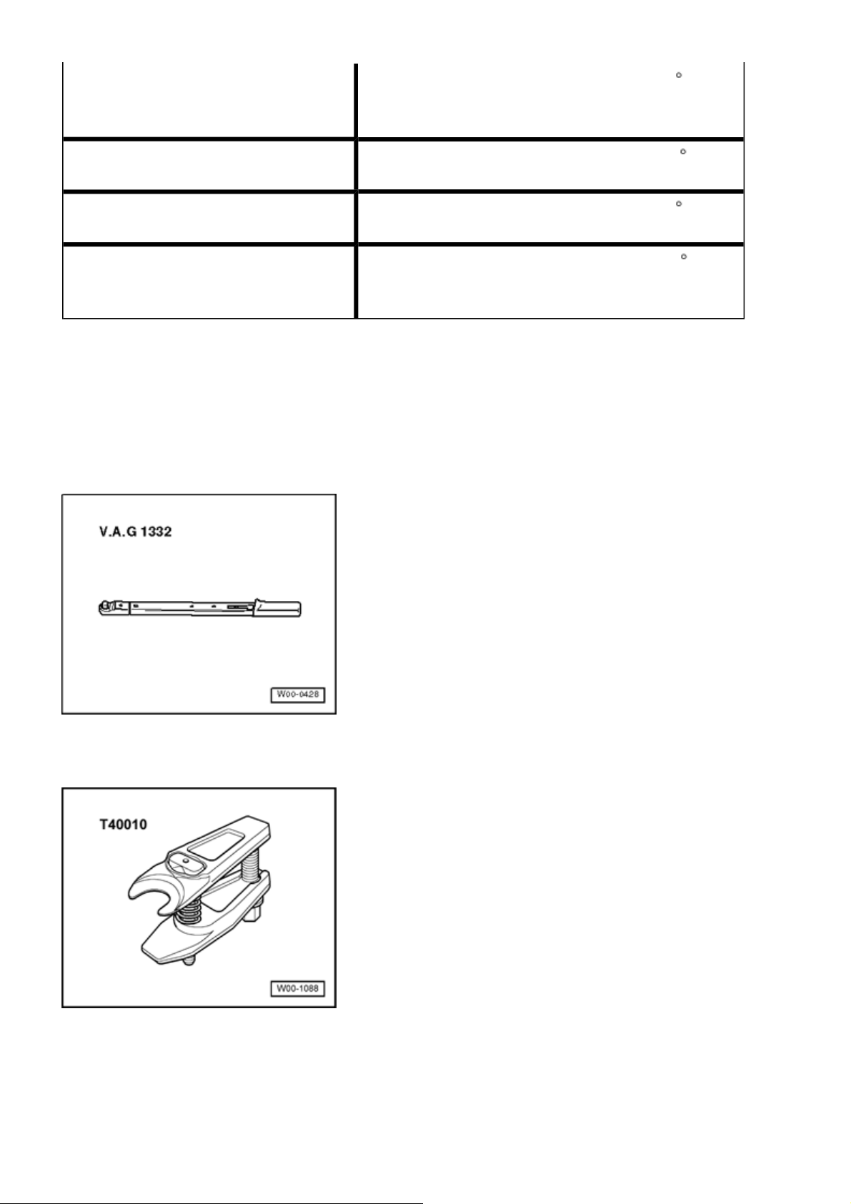
Стр. 16 из 17B - Subframe, lower link, and stabilizer bar, assembly overview
Air spring strut to lower link
1)
2)
Subframe to body, bolts M14
1)
Subframe to body, bolts M10
1)
Lower link to subframe
1)
2)
1)
Always use new nuts and bolts
2)
Tighten bolts and nuts in curb weight position
90 Nm plus an additional 1 / 4 turn (90 )
130 Nm plus an additional 1 / 4 turn (90 )
40 Nm plus an additional 1 / 4 turn (90 )
70 Nm plus an additional 1 / 2 turn (180 )
Guide link, removing and installing
Special tools, testers and auxiliary items required
Torque wrench V.A.G 1332
Ball joint puller T40010
Removing
Page 52
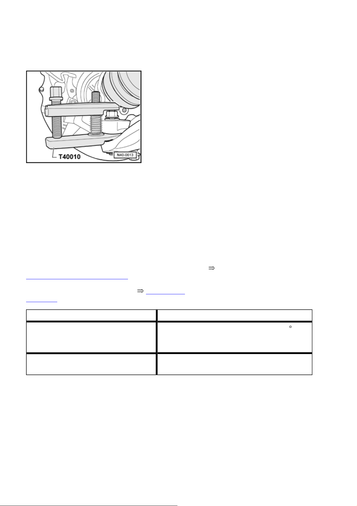
Стр. 17 из 17B - Subframe, lower link, and stabilizer bar, assembly overview
- Remove front wheel.
- Loosen guide link hex nut at wheel bearing housing 2
turns.
- Separate guide link guide pins away from tapered seat
using ball joint puller T40010 .
Do not damage protective joint boot when doing this!
- Remove guide link from subframe.
Installing
Installation is in reverse order of removal, note the
following:
- Raise wheel bearing housing for tightening to subframe
40-2, Lift wheel bearing housing
- Measure vehicle after installation 44-3, Wheel
alignment .
Tightening torque
Guide link to subframe
1)
2)
Guide link to wheel bearing housing
1)
1)
Always use new nuts and bolts
70 Nm plus an additional
120 Nm
1
/ 2 turn (180 )
2)
Tighten bolts and nuts in curb weight position
Page 53
g
j
j
g
Стр. 1 из 32Drive shaft, servicin
g
40 - 5
Drive shaft, servicin
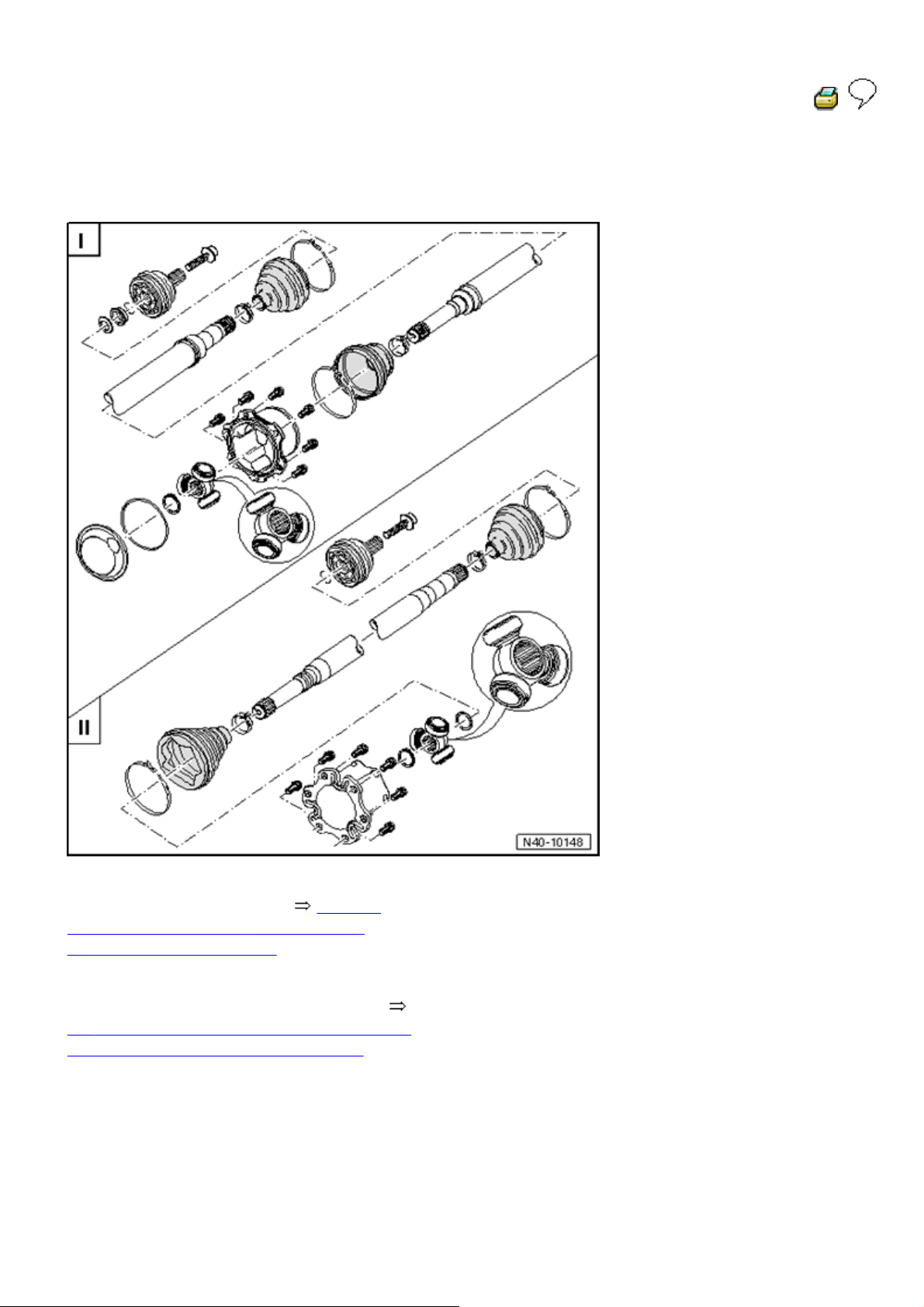
Drive axles, overview
I - Drive axle with triple-roller joint AAR
40
2900, assembly overview
-5, I Drive axle with triple-roller joint AAR
2900, assembly overview
II - Drive axle with peened triple-roller
oint AAR 3300i, assembly overview
40-5, II Drive axle with peened triple roller
oint AAR 3300i, assembly overview
Drive axles, removing and Installin
Removing
During assembly work, make sure that no indentations
form on boot of air spring strut!
Page 54
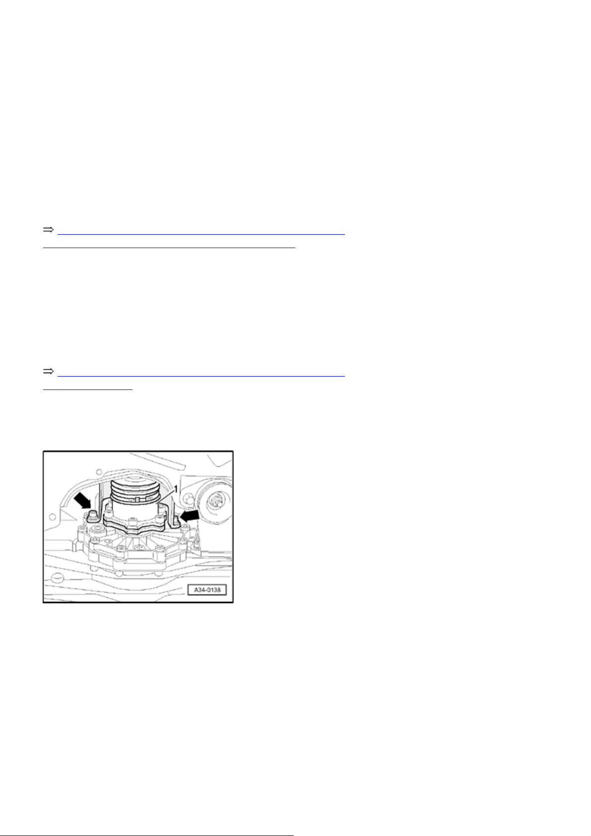
Caution!
-
)
g
g
Remove drive axle hex bolts (only loosen if vehicle is
standing on wheels -danger accident
- Loosen drive axle at transmission flange.
.
Стр. 2 из 32Drive shaft, servicin
- Remove front wheel.
- Remove noise insulation
Repair Manual, Body Exterior, Repair Group 50, Noise
insulation; Noise insulation - assembly overview
.
- Remove ABS speed sensor.
- Remove cover plate
Repair Manual, Brake System, Repair Group 46, Front
brakes, servicing
.
- Remove both upper links from wheel bearing housing.
- Remove drive axle heat shield
can not be seen in illustration.
Left drive axle
- Turn steering gear toward left.
ht drive axle
Ri
- Turn steering gear toward right.
Continued for both drive axles
- Disconnect drive axle from transmission flange and
- arrows -
. The third bolt
Page 55
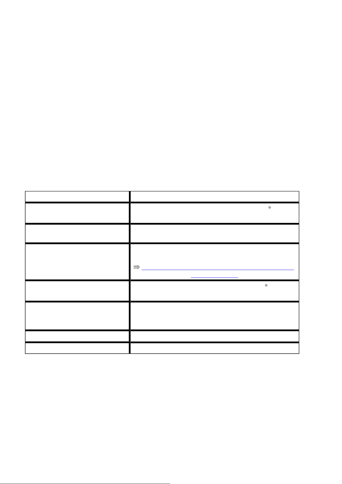
Стр. 3 из 32Drive shaft, servicin
g
remove.
Installing
Installation is in reverse order of removal, note the
following:
During assembly work, make sure that no indentations
form on boot of air spring strut!
- Press upper links as far down as possible when
tightening!
Tightening torque
Drive axle to wheel hub
1)
Cover plate to wheel bearing
200 Nm plus an additional 1 / 2 turn (180 )
10 Nm
housing
ABS speed sensor to wheel bearing
housing
Repair Manual, Brake System, Repair Group 46, Front
brakes, servicing
Upper link to mounting bracket
1)
Drive axle to transmission, pre-
50 Nm plus an additional 1 / 4 turn (90 )
10 Nm
tighten
1)
Drive shaft to transmission, tighten 70 Nm
Heat shield to transmission housing 23 Nm
1)
Always use new nuts and bolts
I - Drive axle with triple-roller joint AAR 2900, assembly
overview
Page 56
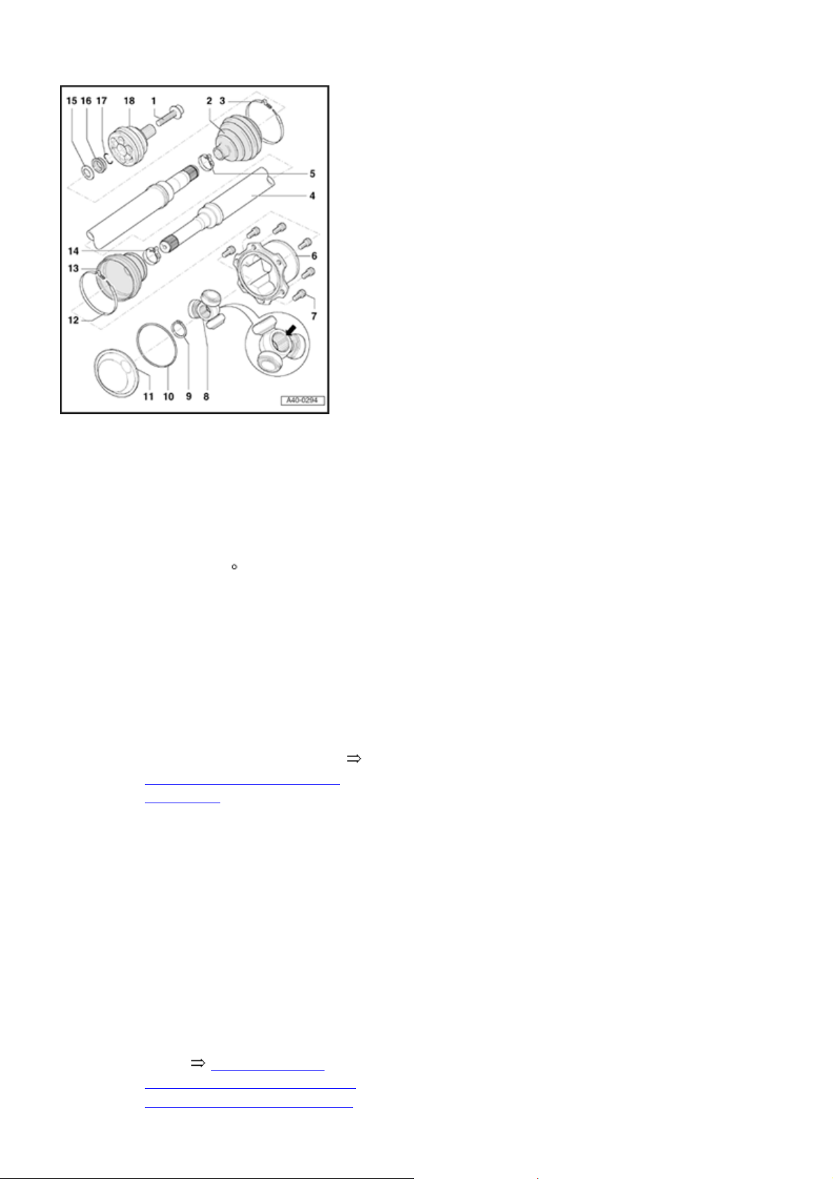
Стр. 4 из 32Drive shaft, servicin
g
Hex head bolt
Always replace
M16 screw tightening torque:
200 Nm plus an additional
turn (180 )
2
Outer constant velocity
protective joint boot
Check for tears and chafing
Before clamping hose clamp,
raise protective joint boot
briefly to balance pressure
40
-5, Protective joint boot,
ventilating
Different version in rubber or
Hytrel
1
/
Clamp
Different versions for
protective joint boot in rubber
or Hytrel
Always replace
Tighten rubber protective joint
boots 40-5, Clamping
sleeves on rubber protective
joint boots are clamped with
Page 57
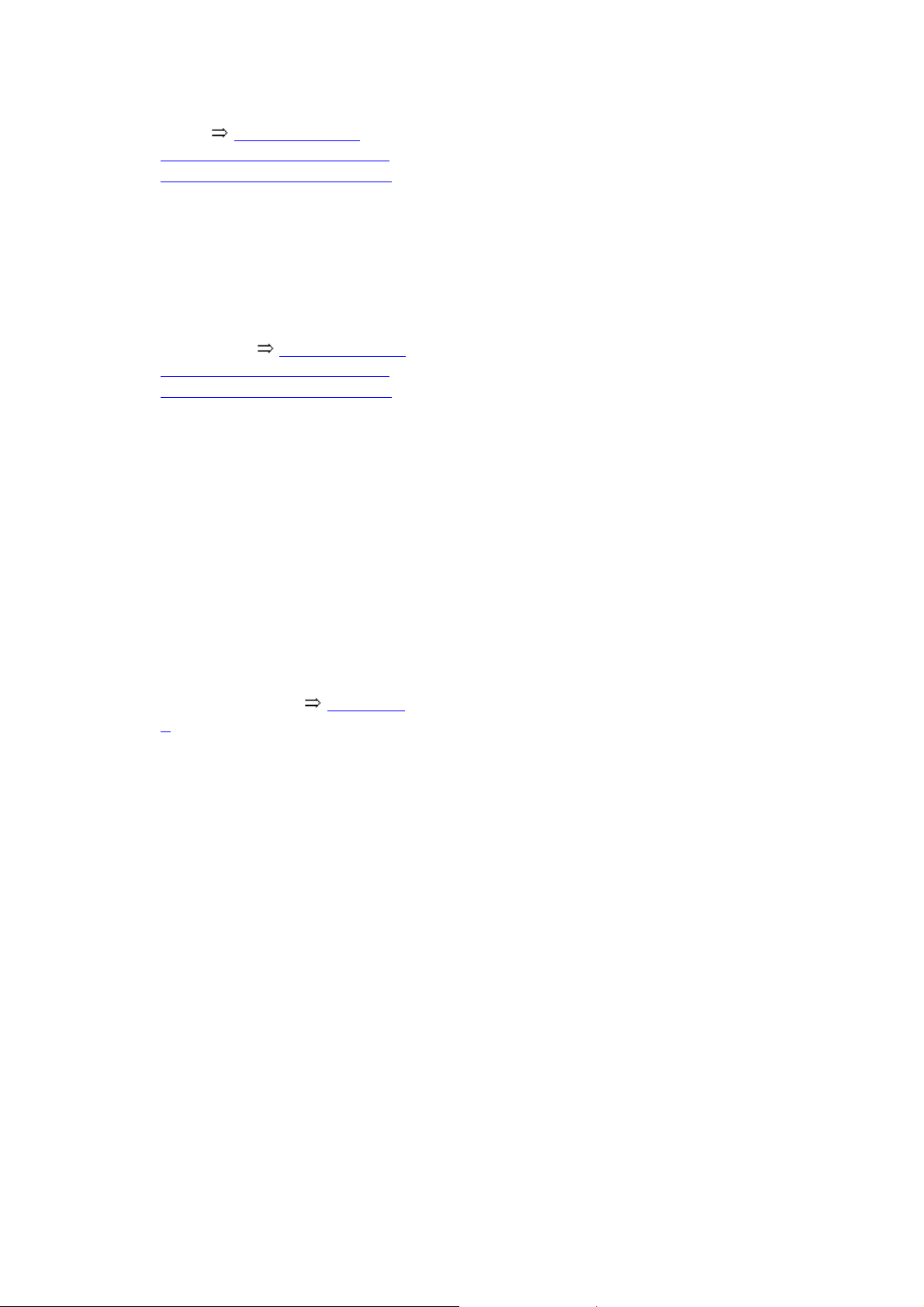
Tighten Hytrel protective joint
g
boots 40-5, Clamping
sleeves on Hytrel protective
joint boots are clamped with
Axle shaft
Clamp
Always replace
Tensioning 40-5, Clamping
sleeves on Hytrel protective
joint boots are clamped with
Joint piece
Стр. 5 из 32Drive shaft, servicin
Multiple point socket head bolt,
70 Nm
Pre-tighten to 10 Nm
Triple roller star
Chamfer - arrow - faces splines
axle shaft splines
Installed location Topic 40-
5
Circlip
Replace each time it is
removed
Insert in shaft groove
O-ring
A new seal is in repair kit and
must be replaced.
Cover
Replace each time it is
removed
Destroyed when disassembling.
A modified cover is included in
the repair kit.
Page 58
g
Clamp
Always replace
Tensioning 40-5, Clamp
large clamping sleeve to inner
joint with
Different hose clamps are
possible depending on
construction. Can also be
assembled with pliers 3340
Electronic Parts Catalog
"ETKA" .
Protective joint boot for triple
roller joint
Стр. 6 из 32Drive shaft, servicin
Clamp
Always replace
Tensioning 40-5, Clamp
small clamping sleeve to inner
joint with
Spring washer
Installed location 40-5,
Installation location of thrust
washer and spring washer
(wheel side)
Thrust washer
Installed location 40-5,
Installation location of thrust
washer and spring washer
(wheel side)
Circlip
Always replace
Insert before mounting in ring
groove (not visible with joint
installed)
Outer constant velocity joint
Replace only as a unit
Page 59
Pressing off 40-5, Pressing
g
off outer constant velocity
joint
Installing: Drive joint onto
shaft with a plastic hammer
until circlip engages.
Checking 40-5, Outer
constant velocity (CV) joint,
checking
Triple-roller joint AAR 2900, disassembling and assembling
Стр. 7 из 32Drive shaft, servicin
Special tools, testers and auxiliary items
required
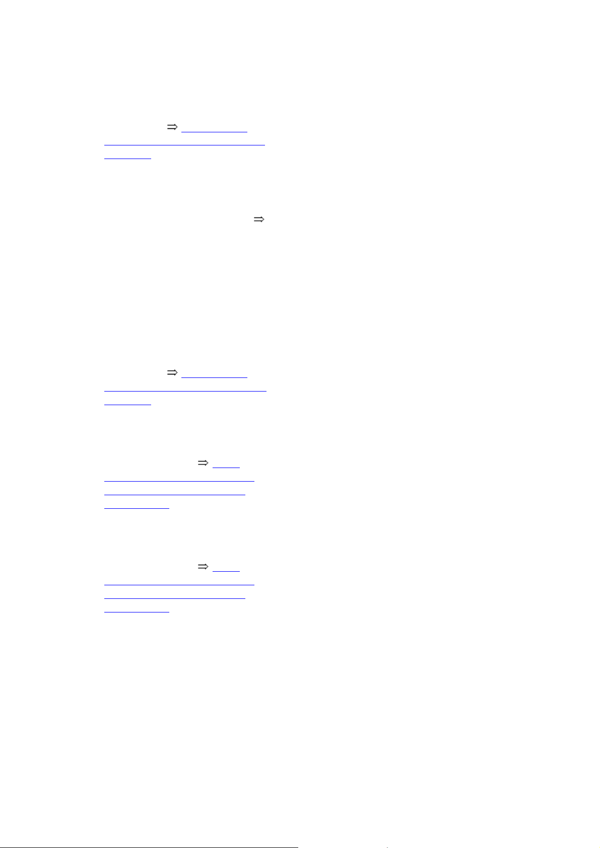
Sleeve VW 416 B
Punch VW 412
Page 60
Стр. 8 из 32Drive shaft, servicin
g
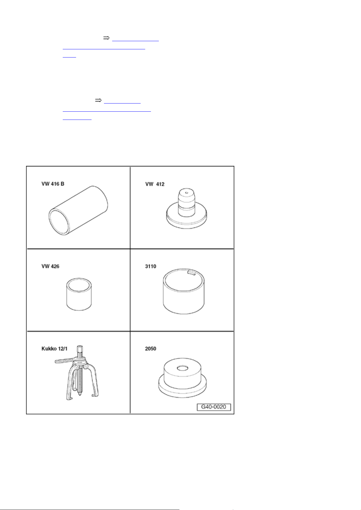
Sleeve VW 426
Sleeve 3110
Puller Kukko 12/1
Press piece 2050
Special tools, testers and auxiliary items
required
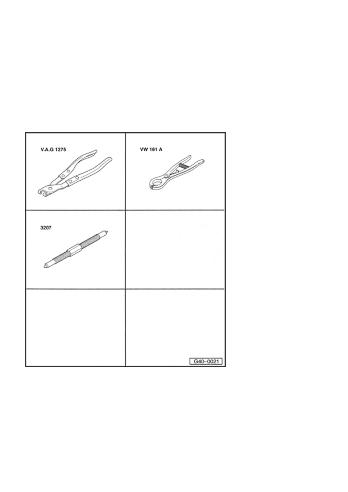
CV joint boot clamp tool V.A.G
1275
Circlip pliers VW 161 A
Pressure spindle 3207
Page 61
Disassemblin
g
j
g
Стр. 9 из 32Drive shaft, servicin
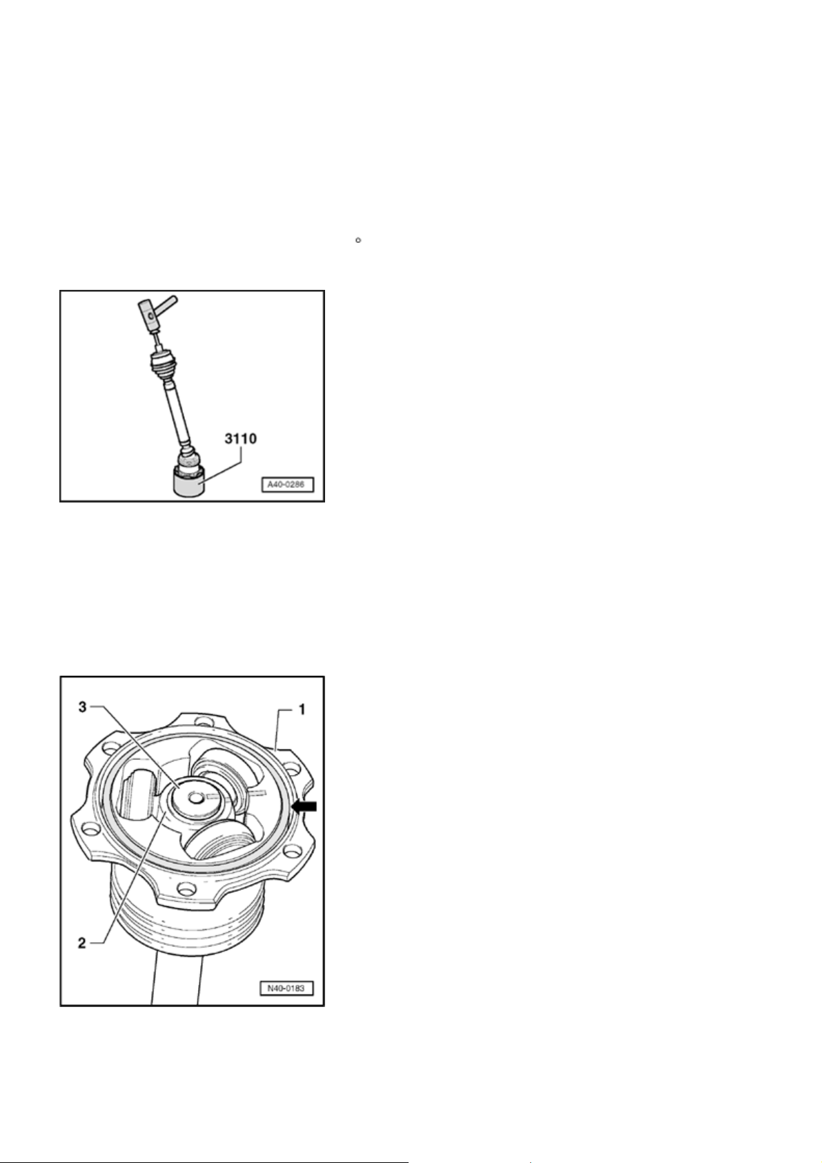
- Line cover.
Note:
Use old screw to line cover.
When doing so, hold shaft at a 20 angle .
Use a plastic hammer and sleeve 3110 .
- Remove any shavings in cover area.
- Open large clamping sleeve.
- Open small clamping sleeve on shaft and slide protective
oint boot back.
- Identify installation location for parts
- 1 -
to
- 3 -
with
lines.
If parts are not marked when assembling, the components
Page 62
are not brought back to their previous installation position
g
g
then it is possible that it will be noisy when driving.
A waterproof felt tipped pen is suitable for marking.
Стр. 10 из 32Drive shaft, servicin
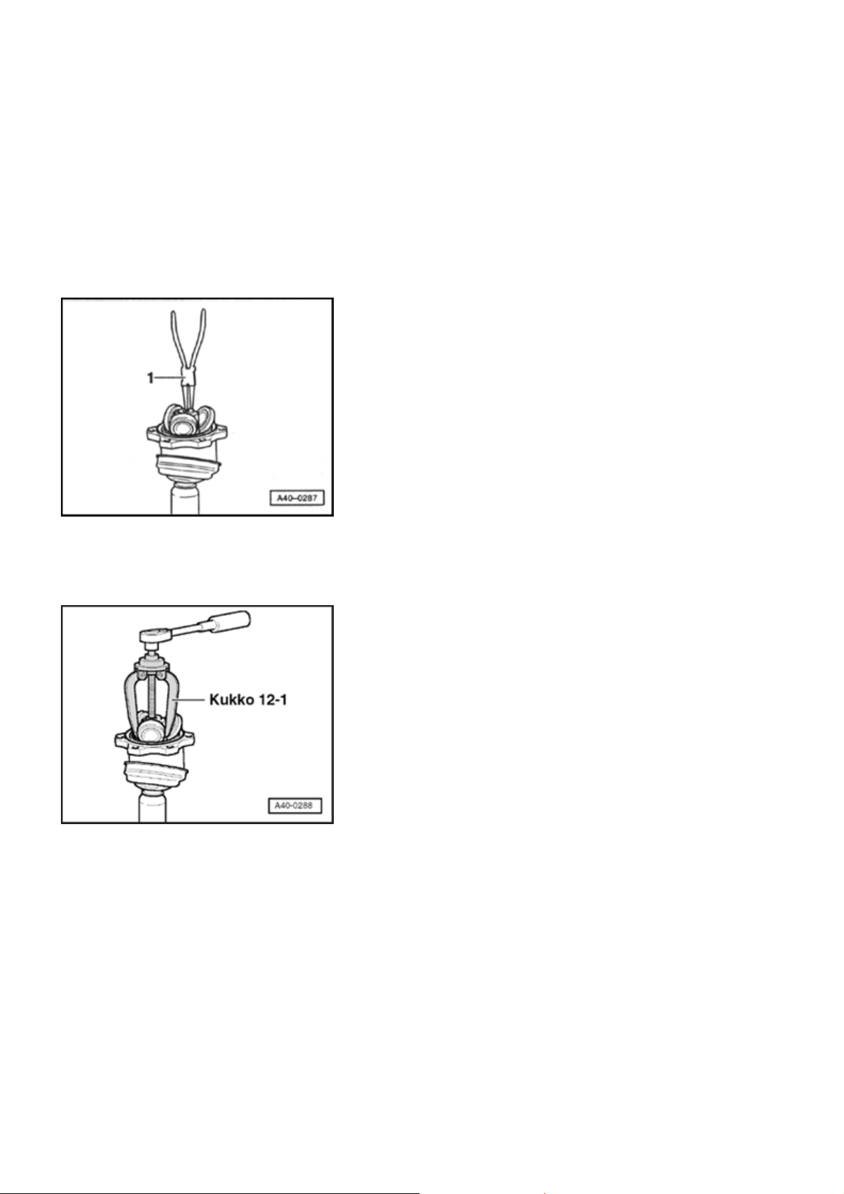
- Remove O-ring
1 - Joint piece
2 - Triple roller star
3 - Axle shaft
- Remove circlip.
1 - Pliers (commercially available)
- arrow -
from groove.
- Remove triple roller star from axle shaft. Use puller Kukko
12/1 (commercially-available) to do this.
- Remove grease in sealing ring groove and on shaft
splines.
- Check roller body and ball cage for wear.
- Clean shaft and housing.
Assemblin
- Slide small protective joint boot clamping sleeve onto
shaft.
- Slide new protective joint boot onto shaft.
Page 63
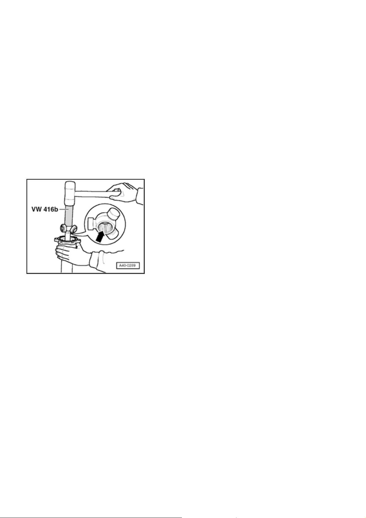
Стр. 11 из 32Drive shaft, servicin
g
- Slide joint onto shaft.
- Slide protective joint boot onto joint.
Mount triple roller star
The chamfer
- arrow -
on star faces toward shaft, this is
used as an assembly aid.
- Place triple roller star onto shaft corresponding to marking
and drive to stop.
- Install circlip. Ensure proper seating.
- Press half of grease G 000 605 from repair kit into triple
roller joint.
- Slide joint over rollers.
Note:
Make sure protective joint boot does not twist.
- Press half of grease G 000 605 from repair kit into rear
side of triple roller joint.
Page 64
Стр. 12 из 32Drive shaft, servicin
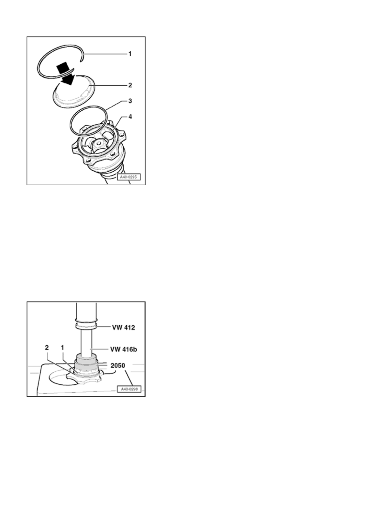
g
- Carefully clean sealing ring groove
- Lay O-ring
- 1 -
in groove
- 4 -
.
- 4 -
.
The individual parts are shown disassembled for sake of
better illustration.
1 - Circlip
2 - Cover from repair kit
3 - O-ring
4 - Groove in triple roller joint
- Lay axle shaft in press.
- Lightly press on cover
from repair kit so circlips from
- 1 -
repair kit can engage.
- Place circlip from repair kit around circumference below
edge.
Note:
Make sure you hear circlip engage.
Page 65
Стр. 13 из 32Drive shaft, servicin
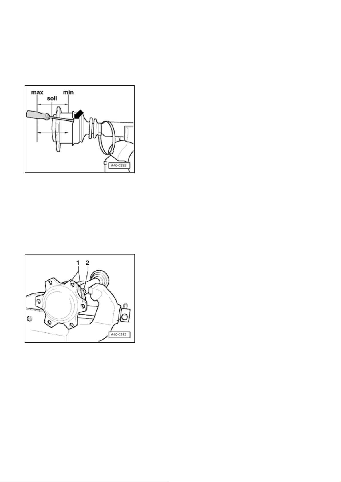
g
- Position joint in middle position, see "min" - "max"
position.
Note:
When positioning joint in middle position, it is
necessary to bleed protective joint boot, e.g. with a
screwdriver
- arrow -
.
- Install clamping sleeve
-2 -
.
Note:
For a better alignment of multi-point socket head
bolts when installing axle shaft, clamping sleeve
connecting tube
connecting flanges
must be between joint
- 2 -
.
- 1 -
Page 66
V
Стр. 14 из 32Drive shaft, servicin
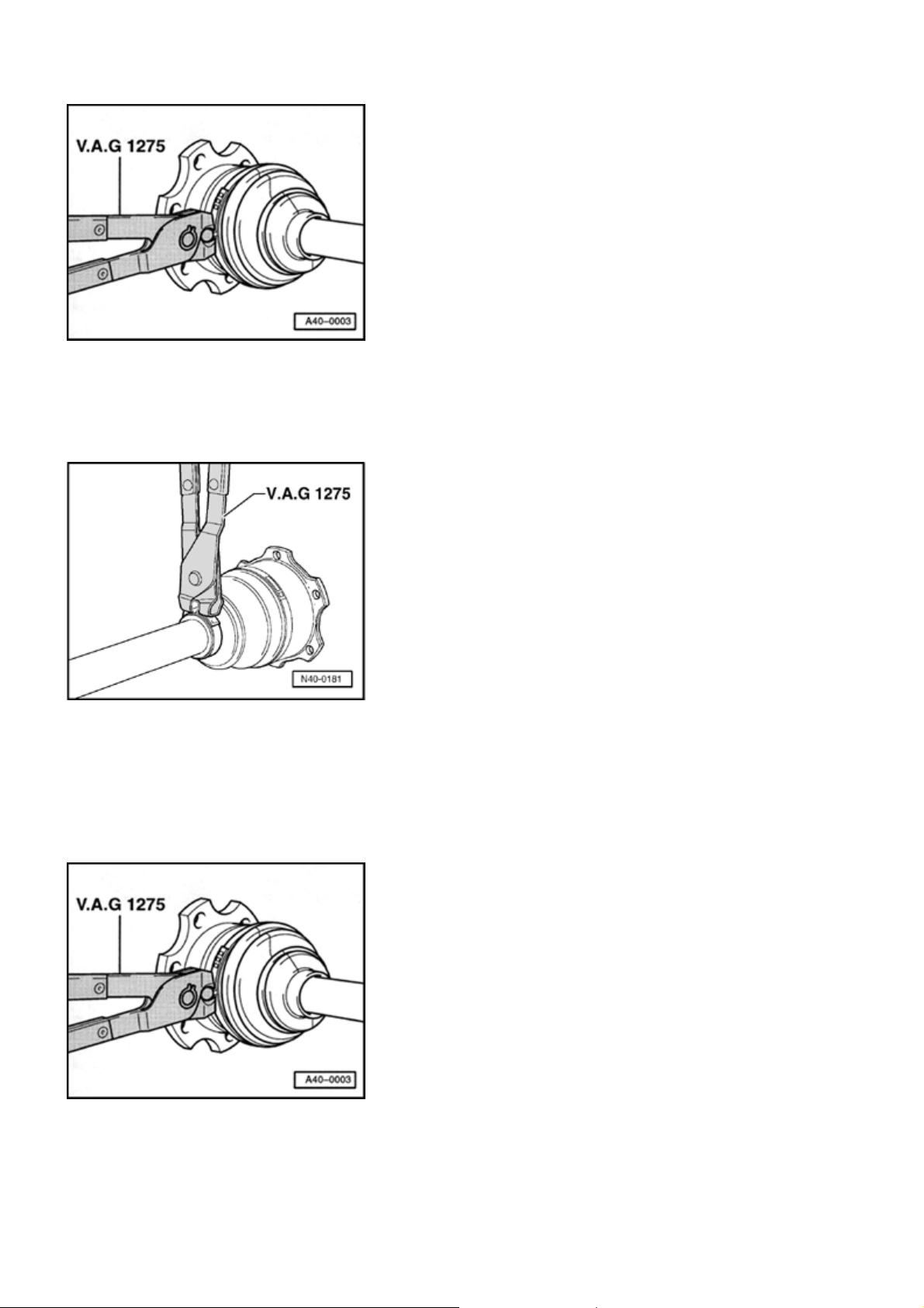
g
Clamp large clamping sleeve to inner joint with pliers
1275
.
Clamp small clamping sleeve to inner joint with pliers
1275
.
Outer constant velocity joint, servicing
V.A.G
V.A.G
Clamping sleeves on rubber protective joint boots are
clamped with pliers
.A.G 1275
.
Page 67
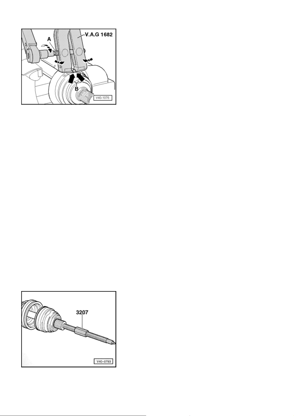
g
Clamping sleeves on Hytrel protective joint boots are
clamped with clamping tool V.A.G 1682 .
- Install clamping tool V.A.G 1682 as shown in illustration.
When doing so, make sure clamping tool jaws are in
corners
- arrow B -
of clamping sleeves.
Стр. 15 из 32Drive shaft, servicin
- Clamp clamping sleeve by turning spindle with torque
wrench (when doing so, do not tilt pliers).
Torque specification: 20 Nm
Use torque wrench with 5 to 50 Nm range (e.g. V.A.G
1331 ).
Be sure thread of spindle of clamp tool moves freely.
Grease with MoS 2 grease if necessary.
If thread is tight e.g. dirty, the required tensioning
force for the hose clamp will not be achieved in spite
of correct torque specification settings.
Pressing off outer constant velocity joint
Page 68
j
j
g
(
)
g
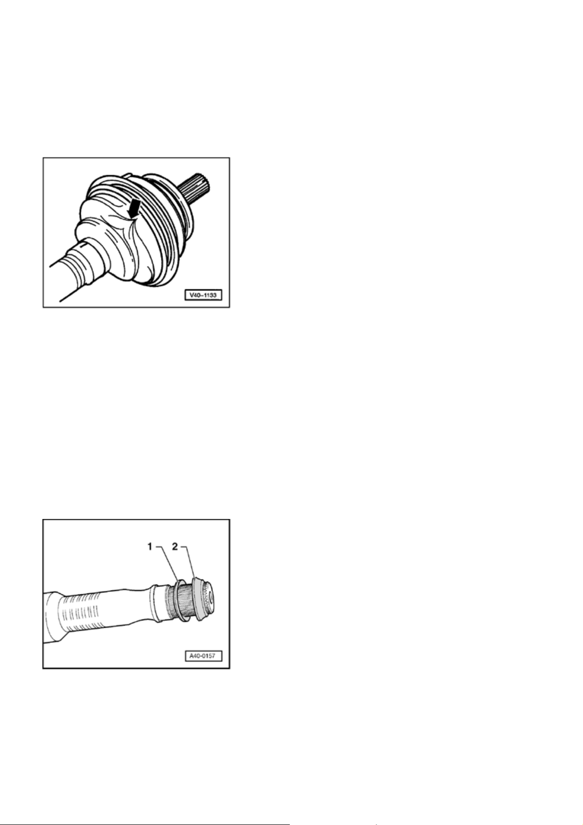
- Clamp drive shaft in vise with protective covers.
- Remove large clamping sleeve and turn back protective
oint boot.
- Screw on pressure spindle 3207 onto guide pins until CV
oint can be removed.
Стр. 16 из 32Drive shaft, servicin
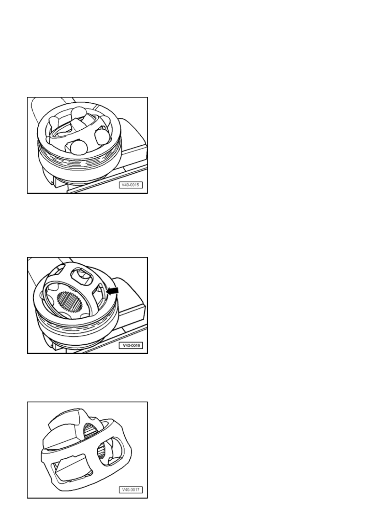
Protective joint boot, ventilatin
Only for rubber protective joint boot:
A vacuum can form in joint when installing protective joint
boot.
This vacuum pulls a fold in when driving
Observe the following:
- Before clamping, clamping sleeves, balance pressure by
raising protective joint boot.
-arrow-
.
Installation location of thrust washer and spring washer
wheel side
1 - Spring washer
2 - Thrust washer (plastic)
Page 69
Outer constant velocity (CV) joint, checking
g
j
g
In order to replace grease in case of strong soiling, joint
must be disassembled or if journal surface of balls must be
checked for wear and damage.
Removin
Стр. 17 из 32Drive shaft, servicin
- Mark ball hub position to ball cage and housing using an
electric scriber or oil stone, before disassembling.
- Pivot ball hub and ball cage.
- Remove balls one after another.
- Turn cage until two rectangular windows
- arrow -
contact
oint body.
- Lift out cage together with hub.
Page 70

- Swing hub segment into rectangular window on cage.
g
y
g
Стр. 18 из 32Drive shaft, servicin
- Tip hub out of cage.
6 balls for each joint belong to a tolerance group. Check
stub axle, hub, cage and balls for small indentations
(pitting) and signs of seizure. Excessive circumferential
backlash in joint makes itself noticed via tip-in shock, in
such cases joint should be replaced. Flattening and running
marks of balls are no reason to replace joint.
Installin
- Press half of total amount of grease into joint body.
- Insert cage with hub into joint body.
- Press in opposite balls one after the other. Reestablish
old position of ball hub to ball cage and to joint body.
- Insert new circlip in hub.
- Distribute remaining grease in cover.
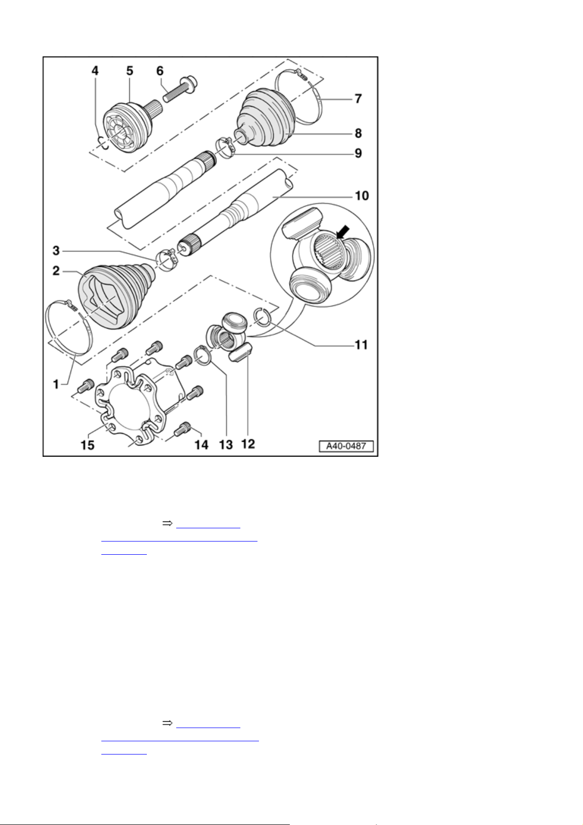
II Drive axle with peened triple roller joint AAR 3300i,
assembl
overview
Page 71
Стр. 19 из 32Drive shaft, servicin
g
Volkswagen Technical Site: http://volkswagen.msk.ru http://vwts.info http://vwts.ru
огромный архив документации по автомобилям Volkswagen, Skoda, Seat, Audi
Clamp
Always replace
Tensioning 40-5, Clamp
large clamping sleeve to inner
joint with
Protective joint boot for triple
roller joint
Protective joint boot must fit in
groove and on joint contour.
Clamp
Always replace
Tensioning 40-5, Clamp
small clamping sleeve to inner
joint with
Page 72
g
Circlip
Always replace
Insert before mounting in ring
groove (not visible with joint
installed)
Outer constant velocity joint
Replace only as a unit
Removing Topic 40-5
Checking 40-5, Outer
constant velocity (CV) joint,
checking
Стр. 20 из 32Drive shaft, servicin
installing Topic 40-5
Collar screw
Always replace
200 Nm plus an additional
180 ( 1 / 2 turn)
Clamp
Always replace
Tensioning 40-5, Clamping
sleeves on Hytrel protective
joint boots are clamped with
Outer constant velocity
protective joint boot
Check for tears and chafing
Clamp
Always replace
Tensioning 40-5, Clamping
sleeves on Hytrel protective
joint boots are clamped with
Driveshaft
Circlip
Page 73
Application Electronic Parts
g
Catalog "ETKA"
Стр. 21 из 32Drive shaft, servicin
Triple roller star
Chamfer - arrow - faces splines
axle shaft splines
Circlip
Always replace
Insert in shaft groove
Bolt, 70 Nm
Pre-tighten to 10 Nm
Joint piece
Triple roller joint AAR 3300i, disassembling and assembling
Page 74
Стр. 22 из 32Drive shaft, servicin
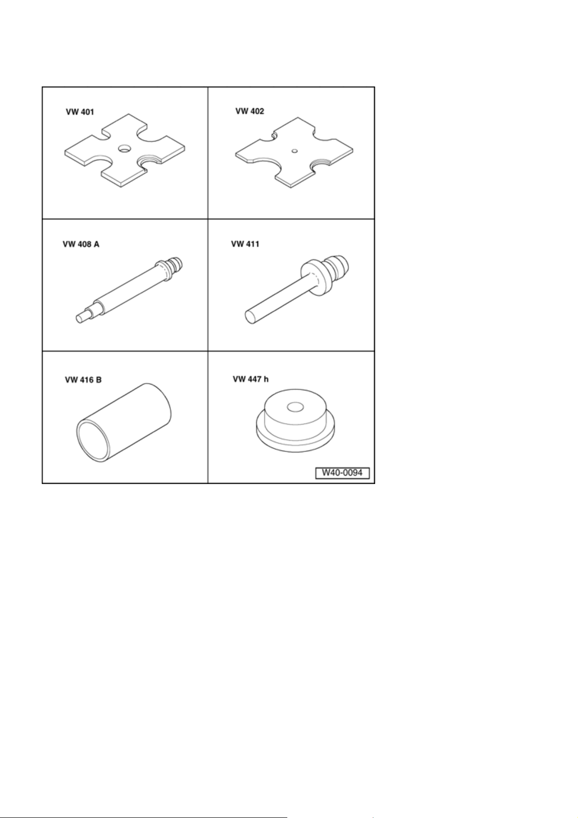
g
Special tools, testers and auxiliary items
required
Thrust plate VW 401
Thrust plate VW 402
Punch VW 408 A
Punch VW 411
Tube VW 416 B
Thrust pad VW 447 H
Page 75
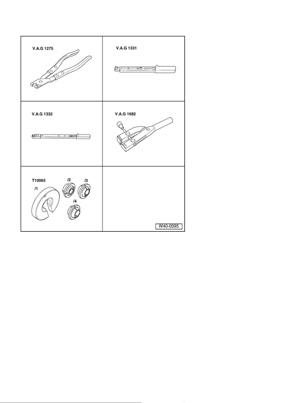
q
p
Стр. 23 из 32Drive shaft, servicin
g
Special tools, testers and auxiliary items
uired
re
CV joint boot clamp tool V.A.G
1275
Torque wrench V.A.G 1331
Torque wrench V.A.G 1332
CV joint boot clamp tool V.A.G
1682
Assembly tool T10065
S
ecial tools, testers and auxiliary items required
Page 76
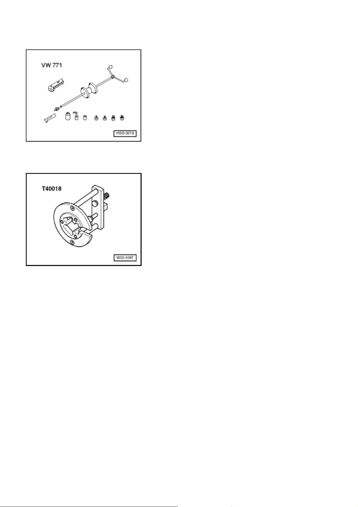
g
Стр. 24 из 32Drive shaft, servicin
g
Slide hammer - complete set VW 771
Assembly tool T40018
Brass or copper drift
Peened triple roller joint AAR 3301, disassemblin
- Clamp joint horizontally in vise.
Note:
Use protective vise covers.
Make sure joint is not damaged.
- Mark location of joint to axle shaft.
If parts are not marked when assembling, the components
are not brought back to their previous installation position
then it is possible that it will be noisy when driving.
A waterproof felt tipped pen is suitable for marking.
Page 77
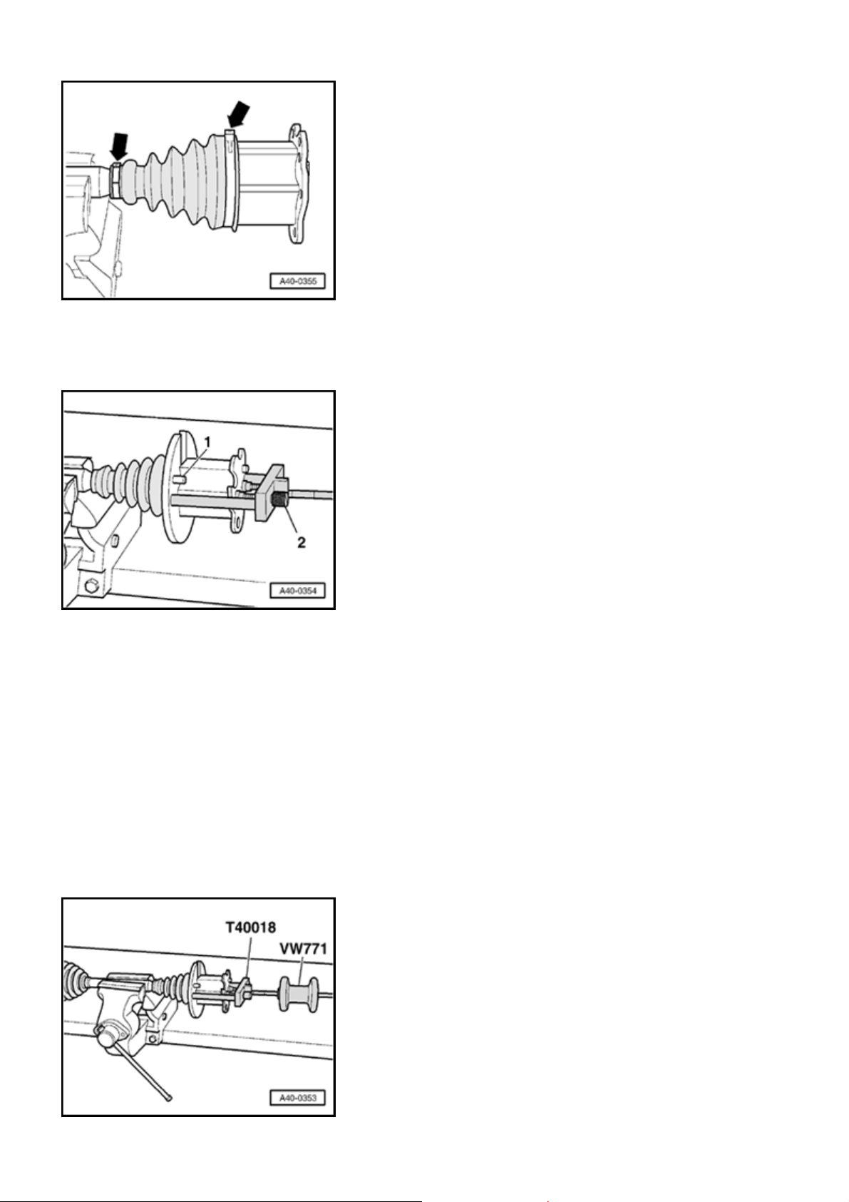
Стр. 25 из 32Drive shaft, servicin
g
- Open clamping sleeves
-arrows -
- Slide protective joint boot back.
.
- Insert assembly device T40018 behind joint.
Guide pins
must contact joint.
- 1 -
- Bring assembly device T40018 into contact with joint by
turning knurled thumb screws
- 2 -
.
Note:
Secure joint in assembly device T40018 with no play.
Only hand-tighten screws
- 2 -
.
Page 78
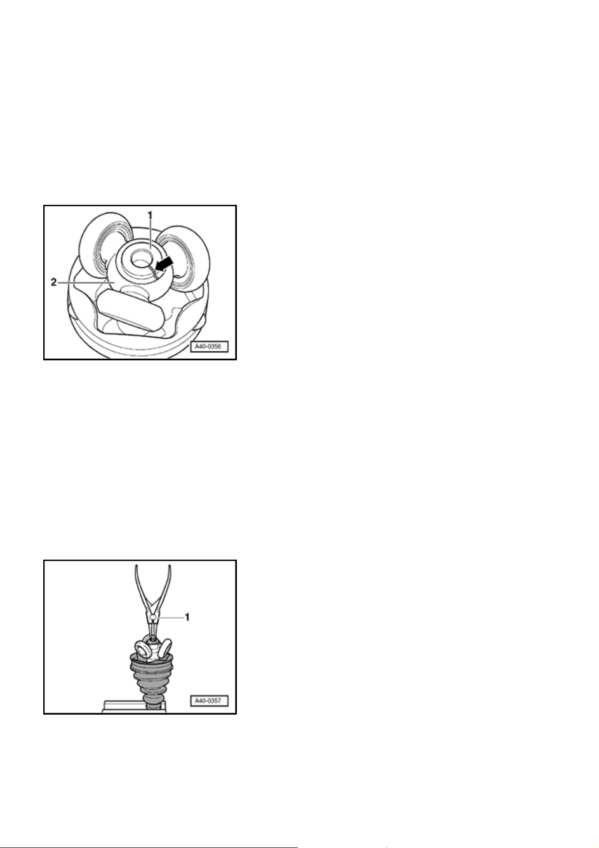
- Screw slide hammer VW 771 into assembly device
g
T40018 .
- Remove joint horizontally with slide hammer VW 771 .
Lower joint in assembly device T40018 .
Стр. 26 из 32Drive shaft, servicin
- Identify installation location for parts
lines.
If parts are not marked when assembling, the components
are not brought back to their previous installation position
then it is possible that it will be noisy when driving.
A waterproof felt tipped pen is suitable for marking.
1 - Axle shaft
2 - Triple roller star
- Remove grease with a lint-free cloth.
- 1 -
and
- 2 -
with
- Remove circlip with pliers
(commercially-available).
- 1 -
Page 79
p
g
Стр. 27 из 32Drive shaft, servicin
g
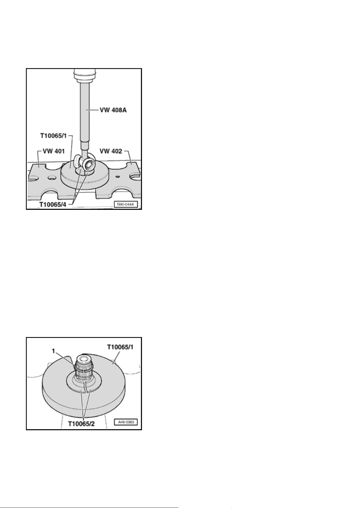
- Press triple roller star off axle shaft.
Assembly tool T10065/4 must not be applied to roller body.
- Remove protective joint boot.
- Remove grease on shaft splines.
- Check roller body and ball cage for wear.
- Clean axle shaft and housing.
le roller joint AAR 3300i, assemblin
Tri
- Slide new protective joint boot onto axle shaft.
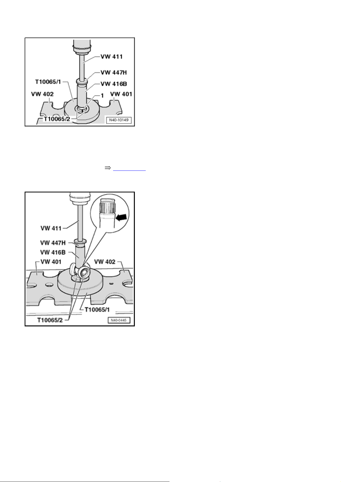
- Press circlip
onto center of splines.
- 1 -
Page 80
Стр. 28 из 32Drive shaft, servicin
g
- To press on circlips
illustration.
Instead of T10065/2 conical axle shafts, cylindrical axle
shafts T10065/3 are used Topic 40-5 .
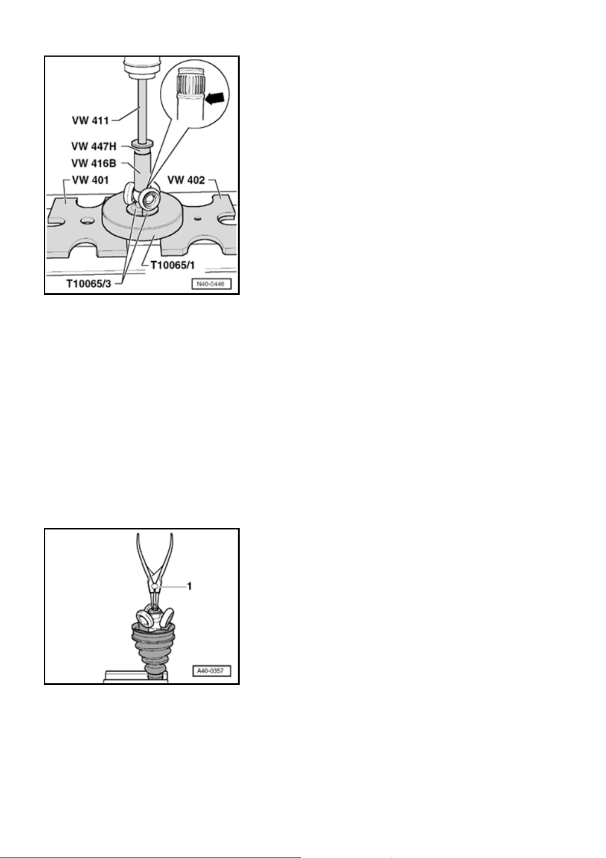
Triple roller star, pressing onto axle shaft
, use special tool shown in
- 1 -
This illustration only applies to conical axle shafts arrow - .
The chamfer on star faces toward axle shaft, this is used as
an assembly aid.
- Use special tool shown in illustration.
Special tool T10065/2 must not come in contact with roller
body.
- Place triple roller star onto shaft corresponding to marking
and drive to stop.
Circlip must engage audibly, triple roller star must lie
against circlip with no gap.
Page 81
Стр. 29 из 32Drive shaft, servicin
g
This illustration is only for cylindrical axle shaft - arrow
- .
The chamfer on star faces toward axle shaft, this is used as
an assembly aid.
- Use special tool shown in illustration.
Special tool T10065/3 must not come in contact with roller
body.
- Place triple roller star onto shaft corresponding to marking
and drive to stop.
Circlip must engage audibly, triple roller star must lie
against circlip with no gap.
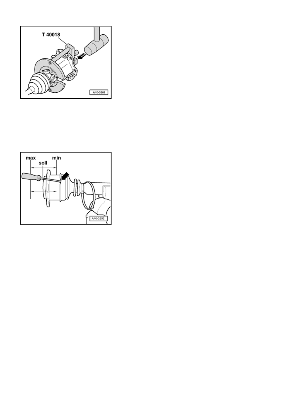
- Install circlip with pliers
- Press half of high-temperature grease from repair kit into
triple roller joint.
- Lightly lubricate roller body.
Make sure roller body does not tilt!
(commercially-available).
-1 -
Page 82
g
- Press joint over triple roller bar with a plastic hammer.
- Press rest of grease into protective joint boot.
- Ensure correct seating of boot on joint.
Стр. 30 из 32Drive shaft, servicin
Boot must fit in groove and on joint contour.
- Position joint in middle position, see "min - max" position.
Note:
When positioning joint in middle position, it is
necessary to bleed protective joint boot, e.g. with a
screwdriver
- arrow -
.
- Install clamping sleeve.
Note:
Page 83
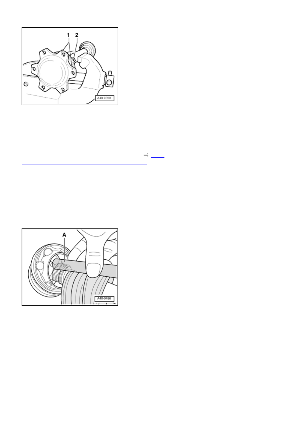
g
For a better alignment of multi-point socket head
bolts when installing axle shaft, clamping sleeve
connecting tube
connecting flanges
must be between joint
- 2 -
.
- 1 -
Стр. 31 из 32Drive shaft, servicin
- Clamp clamping sleeves on triple roller joint 40-5,
Clamp small clamping sleeve to inner joint with
Outer constant velocity joint, servicing
Outer CV joint, removing
- Clamp axle shaft in vise with protective covers.
- Open both clamping sleeves and remove protective joint
boot from CV joint.
- Strike a copper or brass drift
on CV joint inner race
- A -
with a hammer.
- Remove joint and protective joint boot.
Outer CV joint, installing
- Guide protective joint boot with small clamping sleeve
onto joint.
Joints and protective joint boots must be free of grease.
Page 84
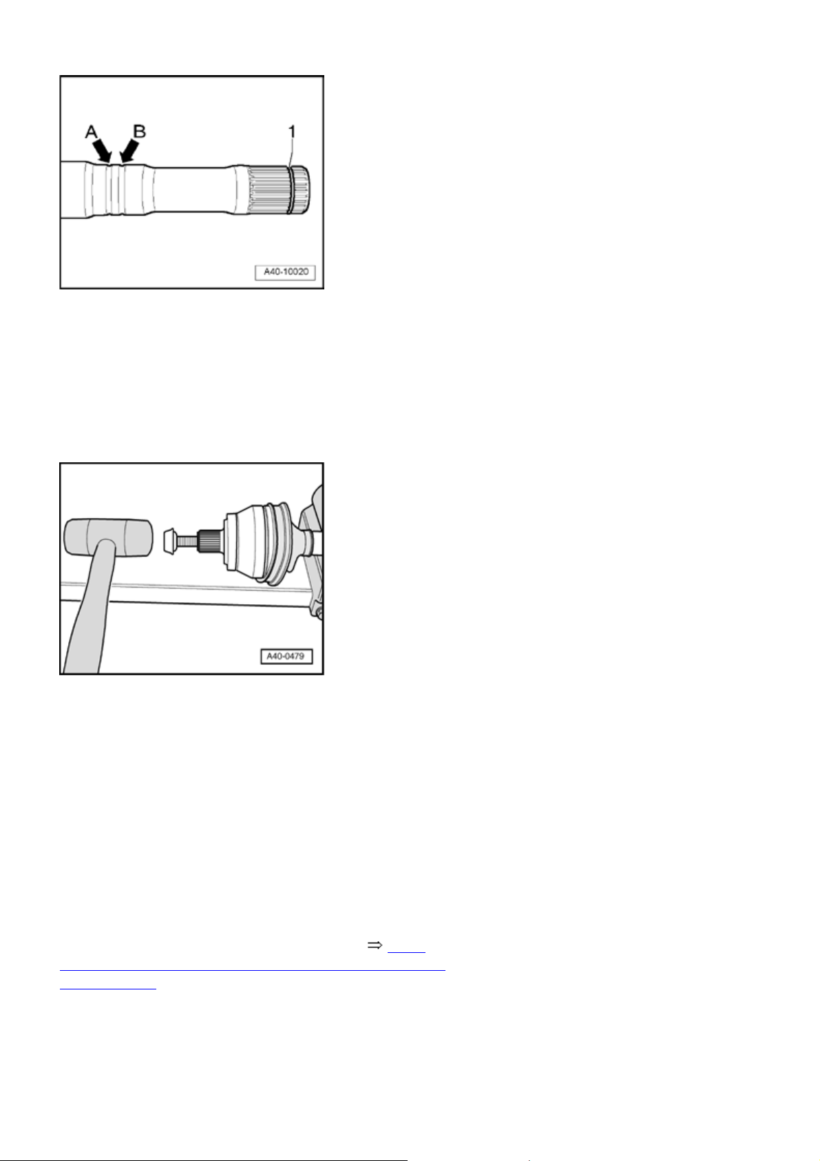
Стр. 32 из 32Drive shaft, servicin
g
- Always replace circlip
- Position protective joint boot in outer groove
Inner groove
groove" (for correct installation of protective joint boot).
- Press half of grease from repair kit into inner joint.
- Screw old axle shaft screw into joint as shown in
illustration.
- arrow A -
.
- 1 -
-arrow B-
must remain visible "identifying
.
- Drive joint onto axle shaft with a plastic hammer until
circlip engages.
- Press rest of grease into protective joint boot.
- Slide protective joint boot onto joint.
- Ensure correct seating of protective joint boot on joint.
Protective joint boot must fit in groove and on joint contour.
- Clamp clamping sleeves onto outer joint 40
Clamping sleeves on Hytrel protective joint boots are
clamped with
-5,
 Loading...