

Page 1
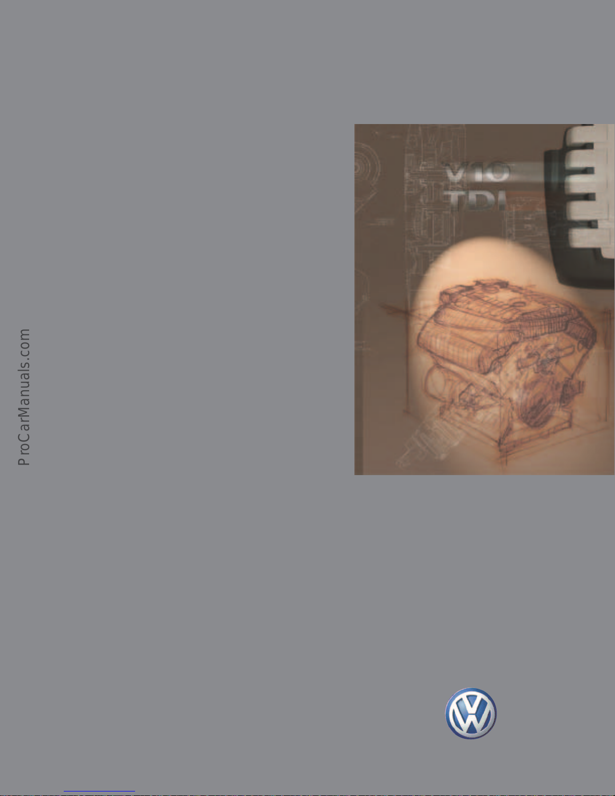
The Touareg
V10-TDI Engine
Design and Function
Self-Study Program
Course Number 89N303
Page 2

Volkswagen of America, Inc.
Service Training
Printed in U.S.A.
Printed 03/2004
Course Number 89N303
©2004 Volkswagen of America, Inc.
All rights reserved. All information contained in
this manual is based on the latest information
available at the time of printing and is subject to
the copyright and other intellectual property
rights of Volkswagen of America, Inc., its
affiliated companies and its licensors. All rights
are reserved to make changes at any time
without notice. No part of this document may
be reproduced, stored in a retrieval system, or
transmitted in any form or by any means,
electronic, mechanical, photocopying, recording
or otherwise, nor may these materials be
modified or reposted to other sites without the
prior expressed written permission of the
publisher.
All requests for permission to copy and
redistribute information should be referred to
Volkswagen of America, Inc.
Always check Technical Bulletins and the
Volkswagen Worldwide Repair Information
System for information that may supersede any
information included in this booklet.
Trademarks: All brand names and product
names used in this manual are trade names,
service marks, trademarks, or registered
trademarks; and are the property of their
respective owners.
Page 3
Contents
Introduction .............................................................................................................. 1
The V10-TDI, Specifications, Power/Torque Diagram
Engine Mechanics..................................................................................................... 4
Cylinder Block,Endbracket, Cylinder Head, Connecting Bolt Principal, Crankshaft,
Crank Pin Offset, Pistons and Connecting Rods, Balancing, Auxilary Drive and Components
Oil Circulation, Coolant Circulation, Fuel System, Exhaust System,
Overview of Engine Management
Service ..................................................................................................................... 40
Service Tools
The Self-Study Program provides you with
information regarding designs and functions.
The Self-Study Program is not a Repair Manual.
For maintenance and repair work, always refer
to the current technical literature.
New!
Caution/Note
i
Page 4
ii
Page 5

Introduction
“...Easy to recognize, the beauty of the classical lines,
the calm but predominantly powerful charisma
of intelligent and sensible engine activity, simple and elegant -
in short, ladies and gentlemen, the world’s top performer!
A milestone...”
With the V10-TDI engine, Volkswagen once again sets new standards in diesel
technology. Due to a multitude of innovative techniques, the highest demands in terms
of performance, torque and emissions of a diesel engine are fulfilled for the luxury
vehicle class.
The V10-TDI engine crowns 25 years of diesel engine development at Volkswagen.
It is the most powerful series passenger-vehicle diesel engine in the world.
1
Page 6
Introduction
The V10-TDI Engine
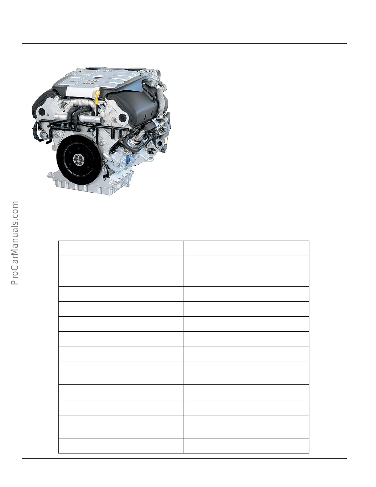
The V10-TDI engine is a newly developed diesel
engine in which innovative lightweight
construction and enormous power are united
within compact dimensions.
It has a 900 aluminum cylinder block with 5
cylinders in each bank of the block. The control
and auxiliary drive are gear-driven. The fuel
injection system uses solenoid controlled unit
injectors to ensure a high performance yield at
low exhaust emissions.
303_001
noitcurtsnoC09,srednilyC01
eroB)mm18(.nI91.3
ekortS)mm5.59(.nI67.3
oisserpmoC1:81
rewopesroHMPR0573@)Wk032(ph803
euqroT
riuqeRleuFmuminimZC94leseiD
edoCenignEWKB
tnemecalpsiD)cc1294(sehcnIcibuC003
rednilyC-rep-sevlaV2
oitaRn
tnemeganaMenignE61CDEhcsoB
stneme
tnemtaerTtsuahxE
0
tfbl355
elgnA-V
MPR0522@)mN057(
dnanoitalucricersagtsuahxE
retrevnoccitylatacnoitadixo
niriF9-4-8-3-7-2-01-5-6-1
redrOg
2
Page 7
240
Introduction
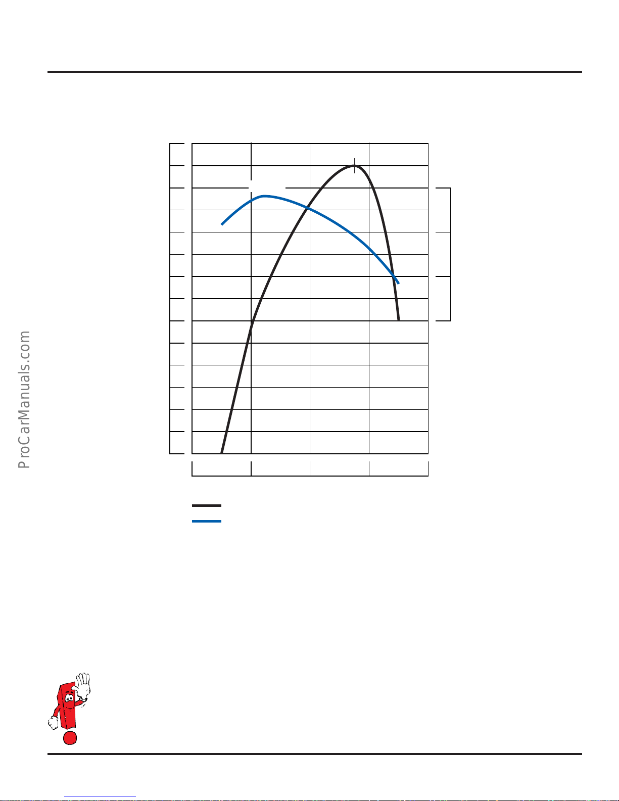
Power Output / Torque
5.0 I - V10 - TDI - 308 hp (230 kW) @ 3750 RPM
533 lb ft (750 Nm) @ 2250 RPM
3,750
220
200
180
160
140
120
100
2,250
800
600
400
200
Torque
(Nm)
1000 2000 3000 4000 5000
Power Output
(kW)
Engine Mechanics Technical Features
• Cylinder block made of aluminum with an
end bracket made of cast-iron
• Joining of cylinder head and cylinder block
with tie-rod bolt connection
• Control and auxiliary drive unit are gear-driven
• Balancer shaft to reduce vibrations
A detailed description of the engine management system can be found in Self-Study Program No.
89P303 “Touareg Electronic Diesel Control EDC 16”, design and function.
= Power Output
= Torque
Engine (RPM)
Engine Management Technical Features
• EDC 16
• Two Engine Control Modules
• Pneumatic controlled exhaust gas
recirculation with electric motor operated
intake manifold flaps
• Oxygen sensors for controlling exhaust gas
recirculation
3
Page 8
Engine Mechanics
Cylinder Block
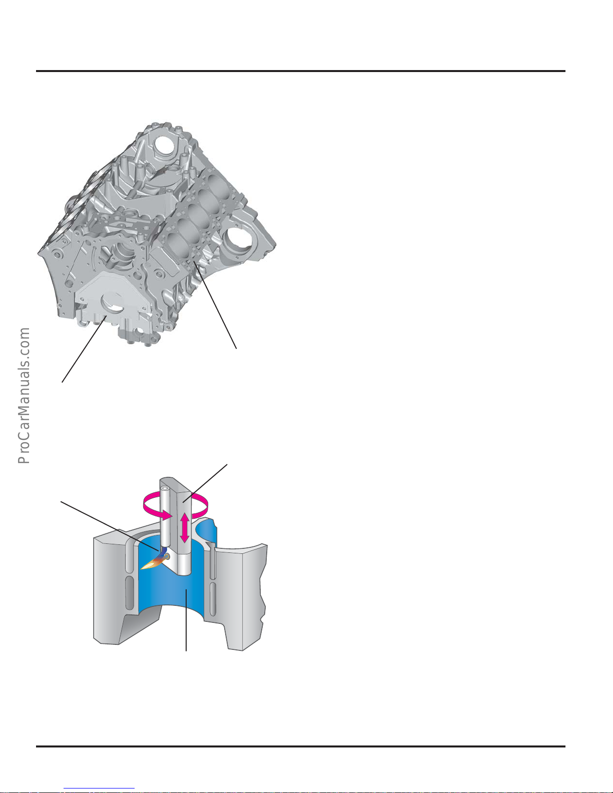
The cylinder block assembly consists of three
components; an aluminum cylinder block, upper
and a lower end brackets. The aluminum
cylinder block provides a significant weight
reduction for the 90° cylinder banks. The high
tensile cast iron end brackets give the assembly
a rigid platform.
303_031
End Brackets
Plasma Jet
Cylinder Wall
Top Portion of
Cylinder Block
Plasma Burner
Plasma-Sprayed Cylinder Walls
For the first time in diesel engines, a plasmasprayed running film is applied to the cylinder
walls. As a result, the use of cylinder liners in
the aluminium cylinder block is no longer
necessary. This reduces the weight of the
engine and permits compact dimensions due to
a short distance between the cylinder bores.
303_069
4
Page 9
Engine Mechanics
End Bracket
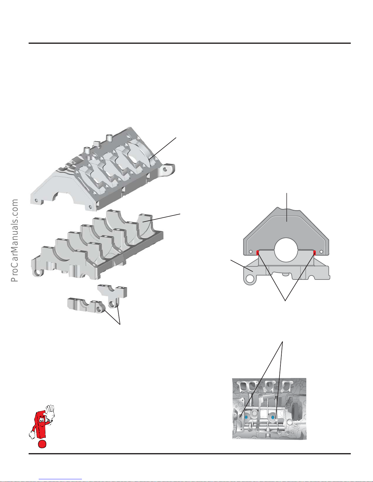
The upper and lower end brackets are manufactured from high tensile cast iron. The upper and
lower portions of the end brackets use a press fit; and 4 bolts per main journal to provide the
crankshaft with a strong and rigid structure to contain the high combustion forces of the diesel
engine.
End Bracket,
Upper Portion
Crankshaft Bracket
Upper Portion
End Bracket,
Lower Portion
Balancer Shaft Thrust Bearing
The cylinder block will be damaged or
deformed by loosening the bolts
connecting the cylinder block with the
upper portion of the end bracket .
End Bracket ,
Lower Portion
303_077
303_087
Press Fit
Bolted Connection
303_022
5
Page 10
Engine Mechanics
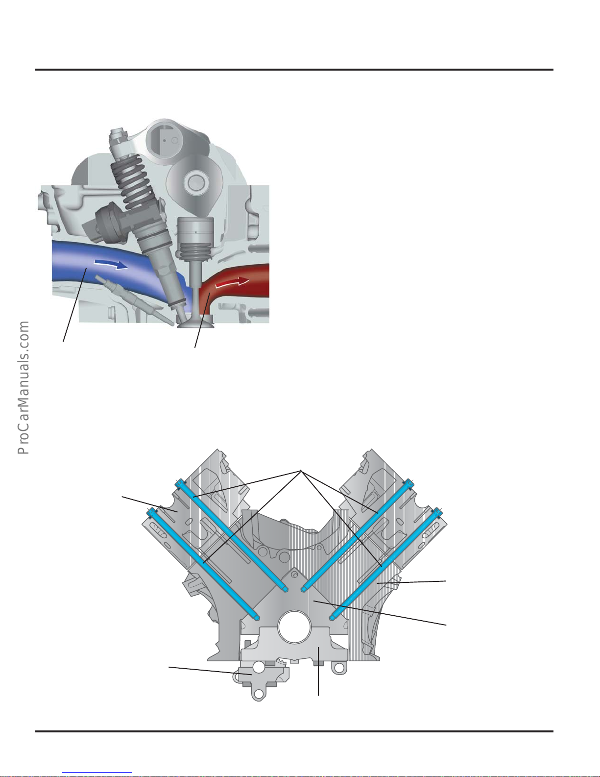
Intake Port
Exhaust Port
Cylinder Head
The V10-TDI engine has two aluminium-alloy
cylinder heads. The intake and exhaust ports are
arranged according to the crossflow principle;
that is, the intake and exhaust ports are located
on opposite sides of the cylinder head. This
arrangement provides good gas exchange and
thus good cylinder filling. The intake ports are
located in the V space of the engine, while the
exhaust ports are on the engine exterior.
303_025
Connecting Bolt Principle
To prevent tension in the cylinder block, the
cylinder heads, cylinder block, and upper portion
of the end bracket are bolted to each other
using connecting bolts.
Cylinder Head
Connecting Bolts
Cylinder Block
End Bracket,
Upper Portion
Balancer Shaft Bearing
6
303_049
End Bracket,
Lower Portion
Page 11
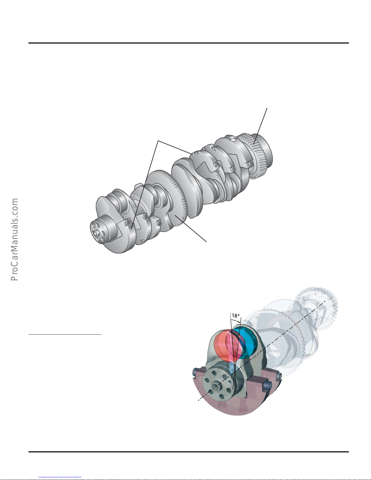
Crankshaft
The crankshaft of the V10-TDI engine is made of
tempered steel; forged from one piece. The
auxiliary drive gear, engine speed sensor wheel,
and bolted-on counterweights are located on
the crankshaft.
Bolted-on Counterweights
Engine Mechanics
Auxiliary Drive Gear
Crank Pin Offset
The cylinders of a 4-stroke engine fire within
two complete revolutions of the crankshaft
(720°). To attain uniform ignition, the ignition
angle for a 10 cylinder engine must be 72°.
720° crankshaft angle
10 cylinders
A 10 cylinder V-engine must therefore have a Vangle of 72°:
Since the V10-TDI engine has a V-angle of 90°,
the crank pin must be offset by 18° to attain
uniform ignition:
= 72° ignition angle
303_023
Engine Speed Sensor Wheel
90° V-angle – 72° ignition angle = 18° crank pin offset
303_107
7
Page 12
Engine Mechanics
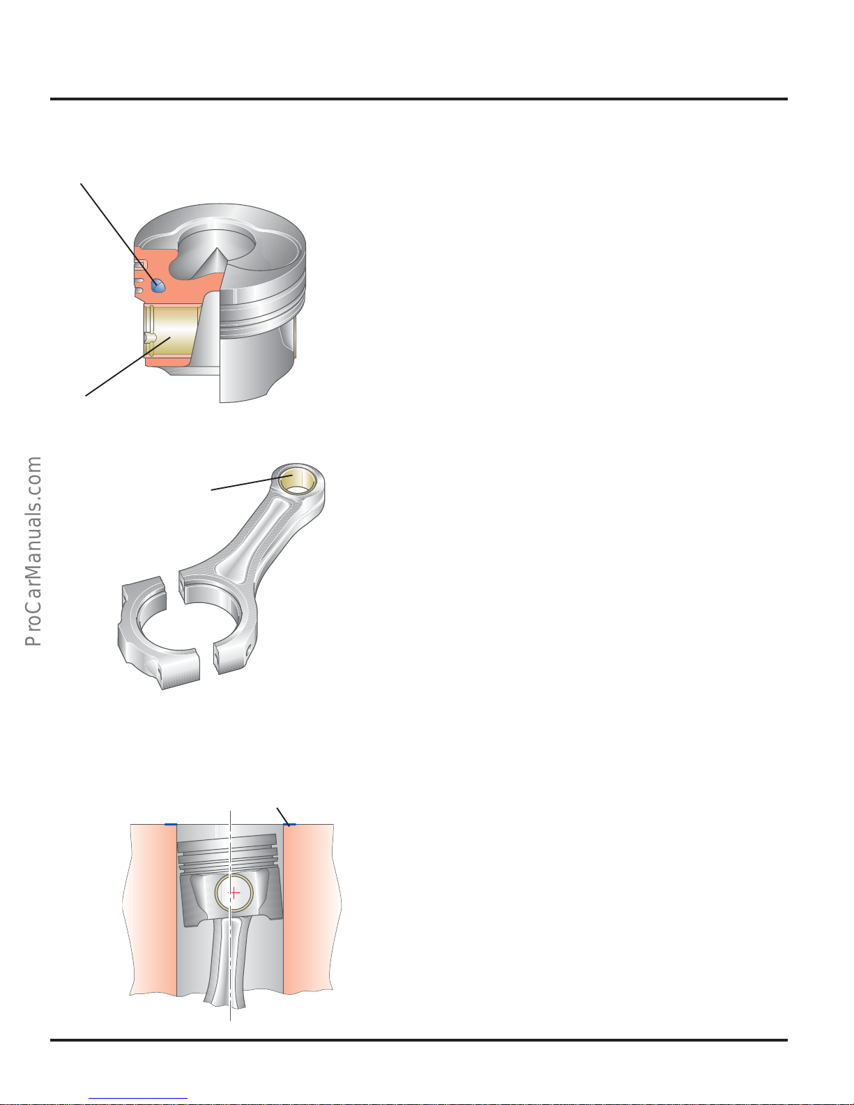
Cooling Channel
Brass Bearing
303_097
Pistons and Connecting Rods
To keep the demands on the piston and
connecting rods low at high combustion
pressures, the piston pin bosses and the
connecting rod boss have a trapezoidal shape.
This distributes the combustion forces over a
broader area. The piston pin bosses are also
strengthened by brass bearings.
A cooling channel is infused into the piston to
cool the piston ring zone. Oil is injected into this
cooling channel from the oil-spraying jets as
soon as the piston is located at bottom dead
center.
Connecting Rod
Brass Bearing
303_098
Top Dead Center
The connecting rod is forged from a high
density sintered metal. To separate the cap
from the rod a procedure called “Cracking” is
required.
Piston Pin Axis Offset
The piston pin axis is offset to prevent noise
from the tilting of the piston at top dead center.
Each time the connecting rod is in a sloping
position, lateral piston forces occur which
alternately press the piston against the cylinder
walls.
The lateral piston force changes direction at top
dead center. The piston is tilted to the opposite
cylinder wall there, thus resulting in noise.
To prevent this, the piston pin axis is offset.
8
Due to the offset arrangement of the piston pin
axis, the piston changes sides before it reaches
top dead center and then supports itself on the
opposite cylinder wall.
303_099
Page 13
Engine Mechanics
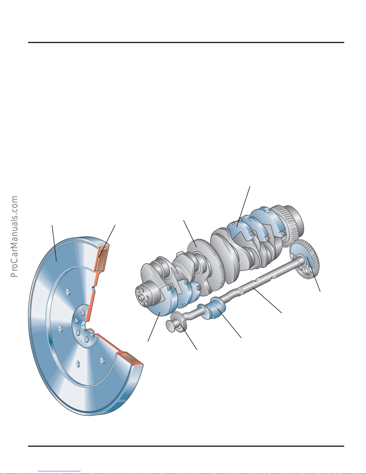
Balancing
To attain low vibration running of the engine, the
moments of inertia must be balanced.
For this, 6 counterweights are attached to the
crankshaft. In addition, a counter rotating
balancing shaft and a weight located in the drive
wheel of the balancing shaft eliminate the
moments of inertia. The balancing shaft is driven
by the crankshaft and serves as a driveshaft for
the oil pump.
The counterweights are made of a tungsten
alloy. As tungsten has a high density, the
weights be small in size, which saves space.
Engine Speed
Vibration Damper
Silicone Oil
Sensor Wheel
Vibration Damper
The vibration damper reduces the rotational
vibrations of the crankshaft. It is filled with a
silicone oil.
The rotational vibrations of the crankshaft are
eliminated by the shear force of the silicone oil.
Counterweight
303_008
Crankshaft
Oil Pump
Drive Gear
Counterweight
Counterweight
Balancing Shaft
303_024
9
Page 14
Engine Mechanics
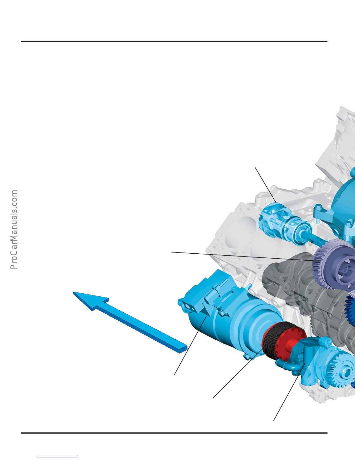
Auxiliary Drive and Components
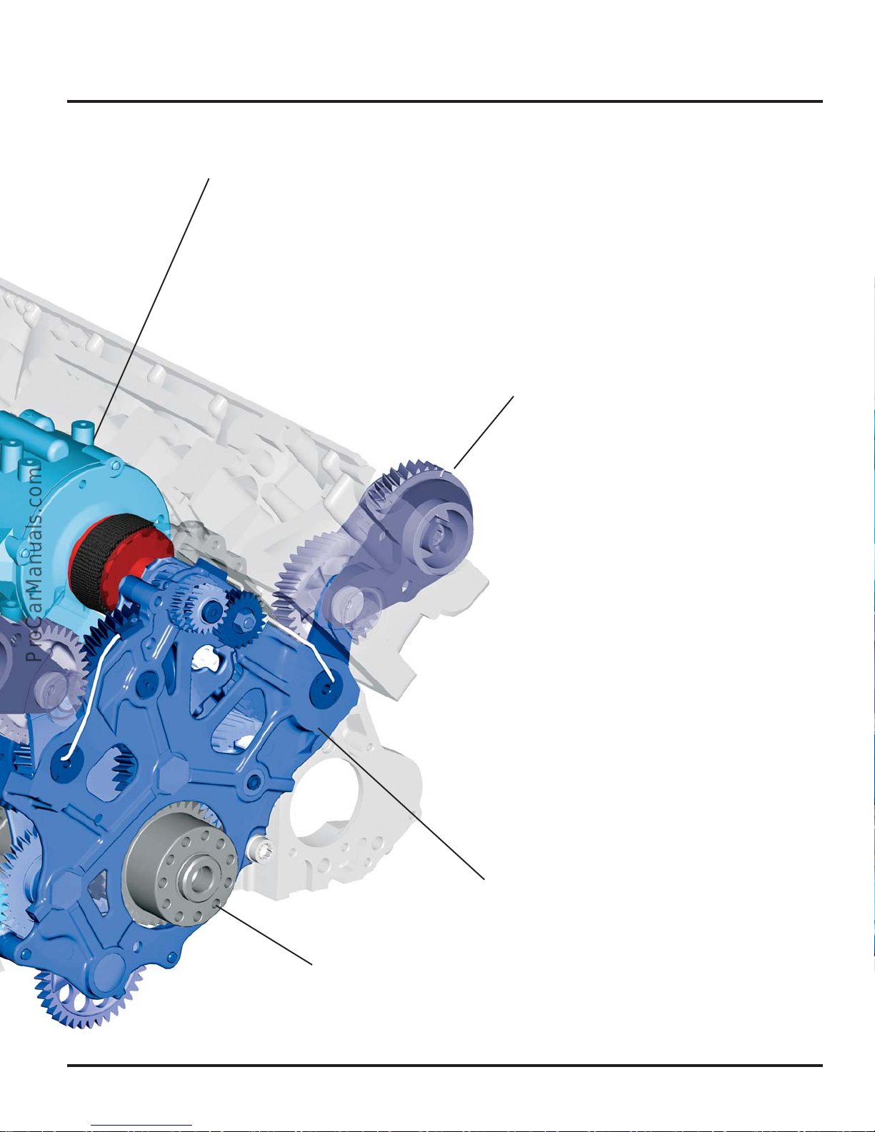
The auxiliary drive is located on the flywheel
side.
The camshafts and the auxiliary components are
driven by the crankshaft by helical gears.
The advantage of a gear drive over a toothed
belt is that larger forces can be transferred while
the size of the gears remains the same as the
sprockets used for toothed belt. In addition, a
toothed belt will stretch with age, changing cam
timing.
The auxiliary drive is also maintenance-free.
Coolant Pump
Camshaft Drive
Direction of Tr a ve l
Air Conditioning (A/C)
Compressor
Gates Drive
10
Power Steering Pump
Page 15
Alternator
Engine Mechanics
Camshaft Drive
Drive Module
Crankshaft
303_016
11
Page 16
Engine Mechanics
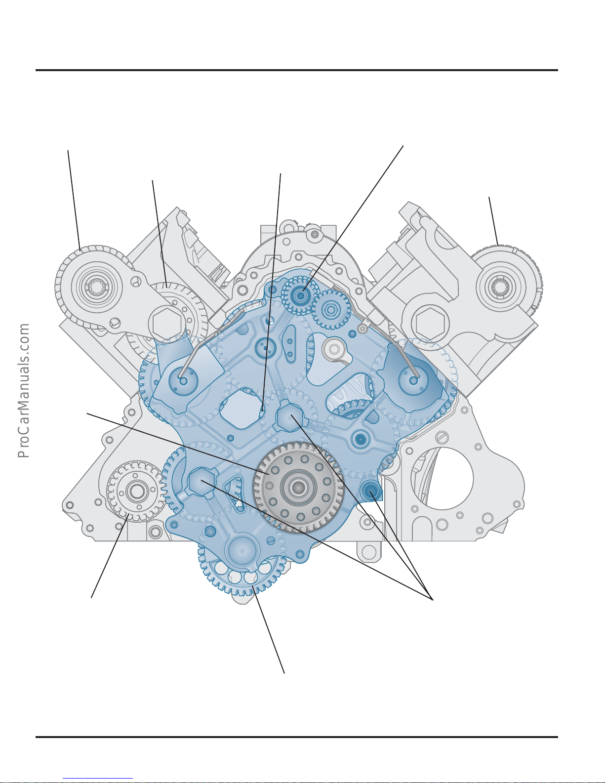
Camshaft Drive Gear,
Cylinder Bank 1
Compensation Gear
Crankshaft
Alternator Drive Gear
Coolant Pump
Drive Gear
Camshaft Drive Gear,
Cylinder Bank 2
Power Steering Pump and
Air Conditioning System
Compressor Drive Gear
303_003
Bolted Connection with Bearing
Tunnel
Oil Pump/Balance Shaft Drive Gear
12
Page 17
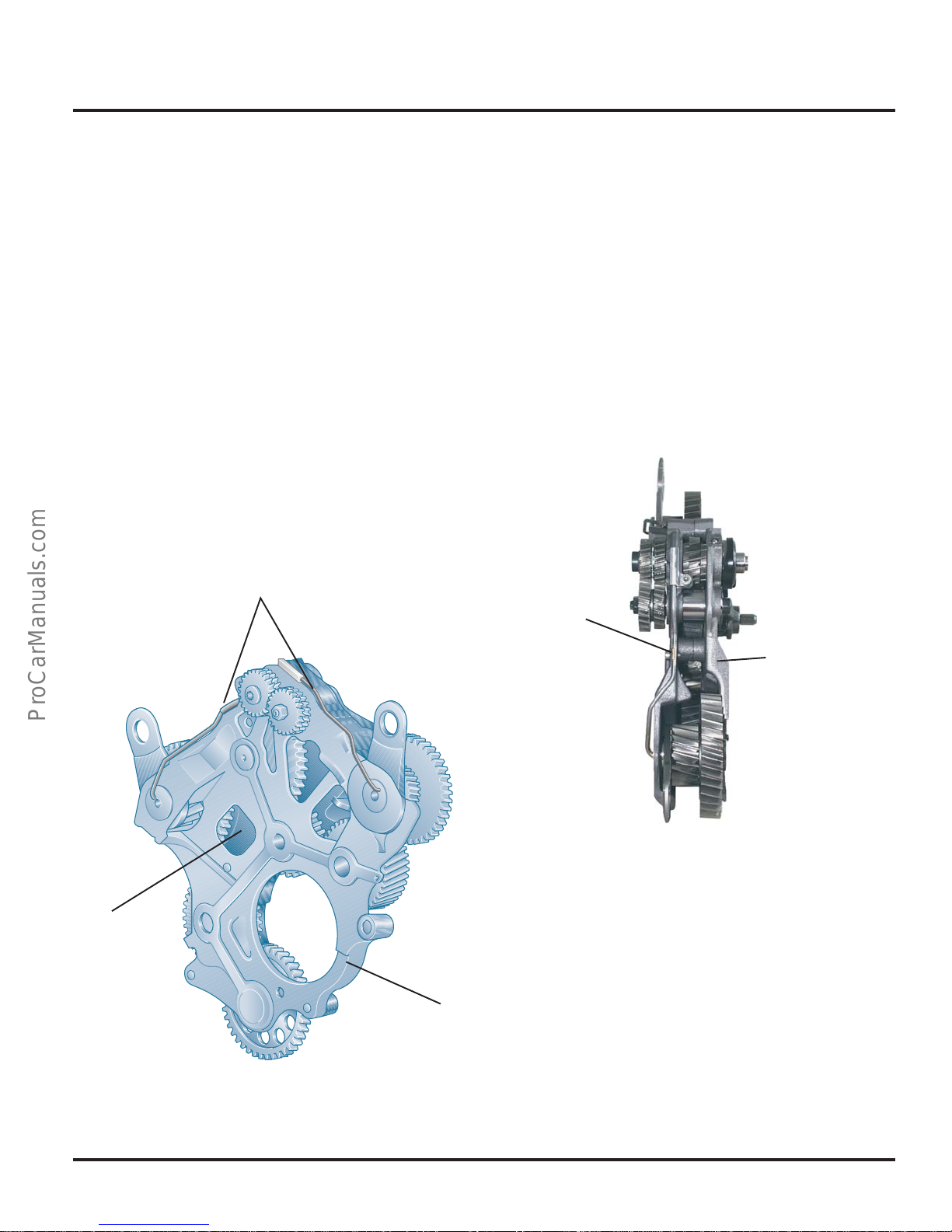
Drive Module
Engine Mechanics
The drive module uses helical gears to drive the
camshafts, coolant pump, alternator, power
steering pump and air conditioning compressor.
The helical gears are mounted in two carrier
plates made of cast iron to provide uniform
expansion through the entire temperature
operating range of the engine.
The drive module is connected by three bolts to
the bearing tunnel formed by the upper and
lower cast iron end brackets.
Oil Supply Line
The gears have a helix angle of 15°; with two
tooth mesh. The two tooth mesh provides a
larger bearing surface that is stronger and
quieter than a spur gear mesh.
Carrier Plate
Carrier Plate
Carrier Plate
303_102
Carrier Plate
303_004
13
Page 18
Engine Mechanics
Shackle Joint
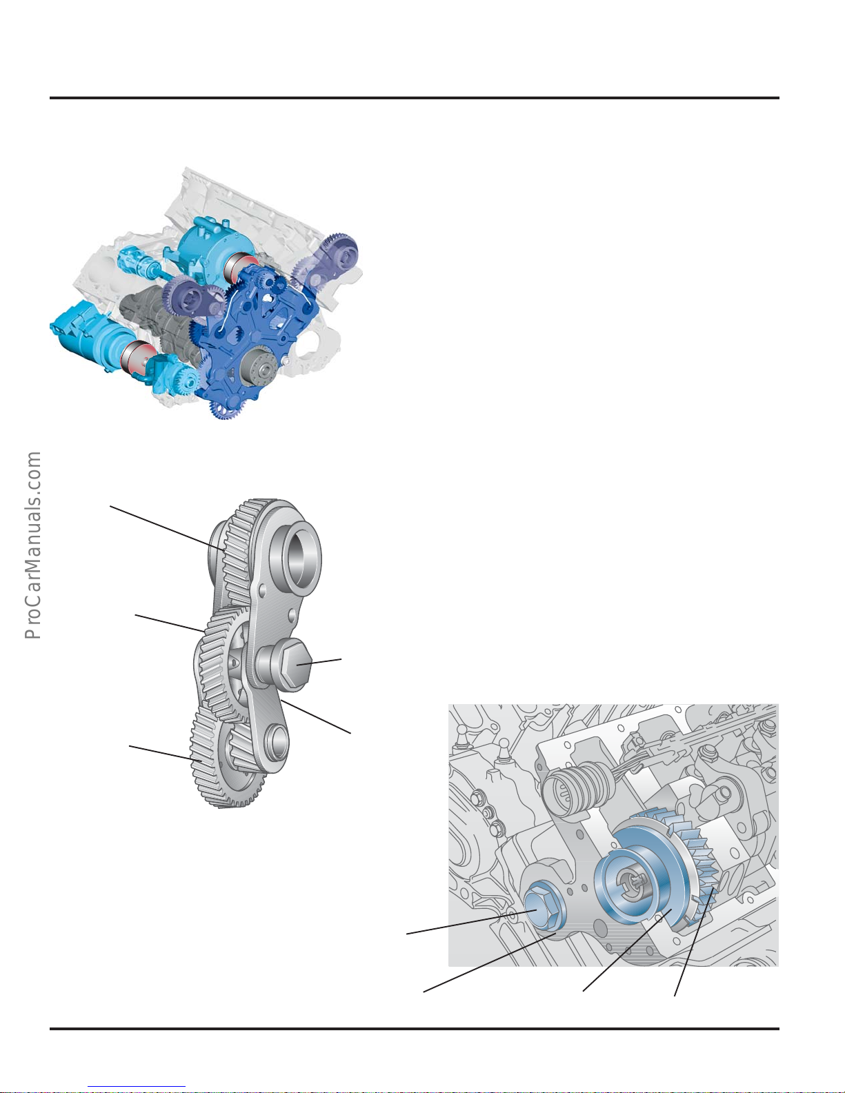
The camshafts located in the cylinder head are
driven by gears located in brackets called a
shackle joint.
The shackle joint is used to compensate for the
end play of the gears and expansion of the
aluminium cylinder heads and cylinder block
throughout the entire operating temperature of
the engine.
303_045
Camshaft
Gear
Compensation
Gear
Drive Gear
How it Works
When subjected to heat, the spacing between
the camshaft to the drive module changes.
The compensation wheel in the shackle joint
follows the joint movement; thus the play
between the wheels within the shackle joint
remains equal.
Balance Piston
Shackle
303_007
14
Balance Piston
Cylinder Head
303_113
Shackle Joint
Camshaft Gear
Page 19
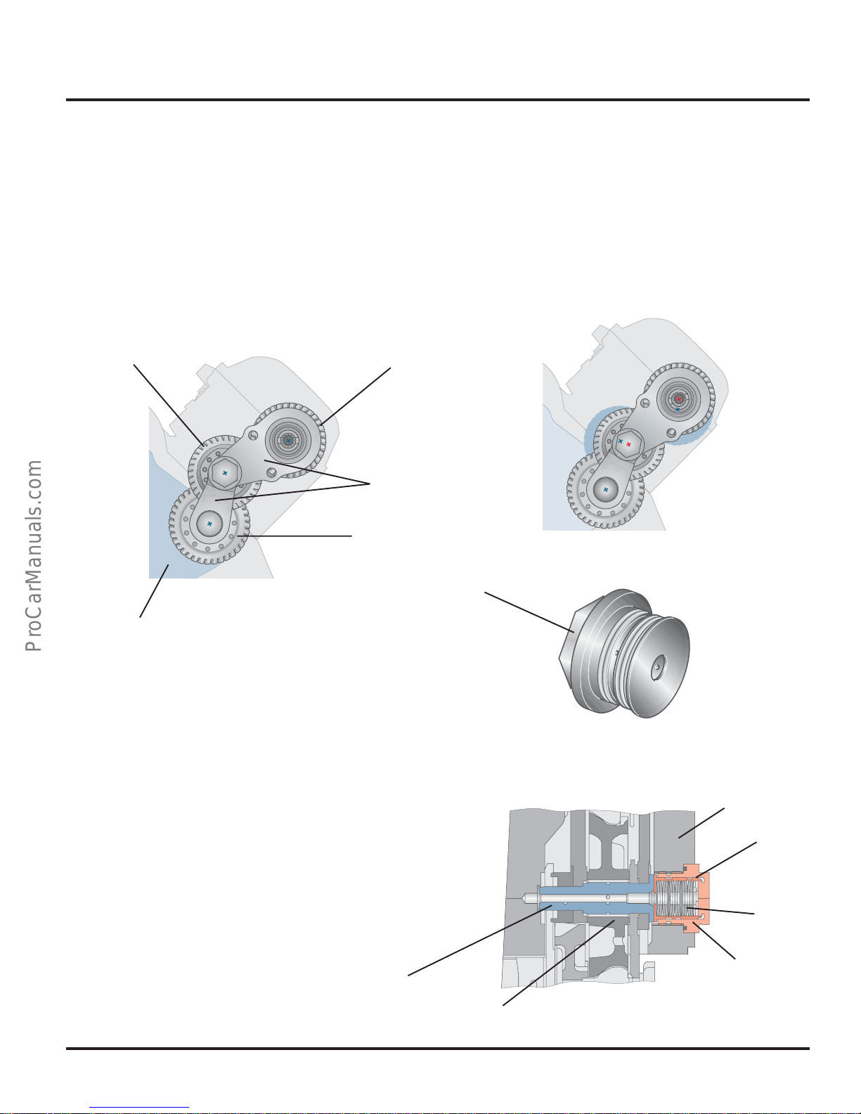
Balance Piston
Preload on the shackle joint is achieved by a
balance piston. The piston consists of a sleeve in
which several spring washers are arranged
behind one another, axially tensioned.
Engine Mechanics
Setting for “Warm Engine”
Compensation
Gear
303_017a
Drive Module
Camshaft Gear
The balance piston is bolted into the cylinder
head. Using a full floating axle, it tensions the
two shackle joints; this prevents “dangling
movements” of the shackle joint.
Shackles
Drive Gear
303_017b
Balance
Piston
303_037
Cylinder Head
Full Floating Axle
Compensation Gear
Sleeve
Spring
Washers
Balance
Piston
303_083
15
Page 20
Engine Mechanics
303_046
Alternator
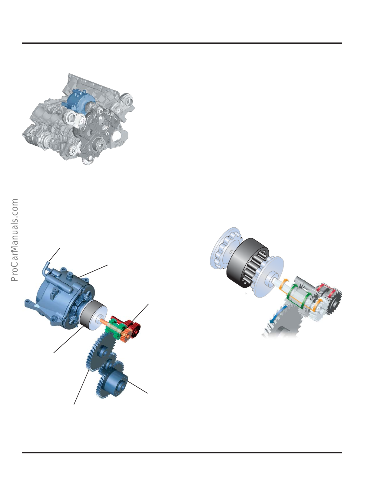
The alternator is arranged in a space-saving
manner in the V-space of the engine.
It is driven by a Gates® drive via a gear drive on
the transmission shaft. Due to the transmission
shaft, the alternator speed increases by a factor
of 3.6 compared to the engine speed.
This provides an increased alternator
performance that can cover high power
demands of the vehicle electrical system even
when idling.
The alternator is liquid-cooled.
Coolant Connection
Gates drive
Powerflow
Alternator
Transmission Shaft
303_101
Gear Drive
16
Crankshaft
303_095
Page 21
Power Steering Pump/Air Conditioning
System Compressor
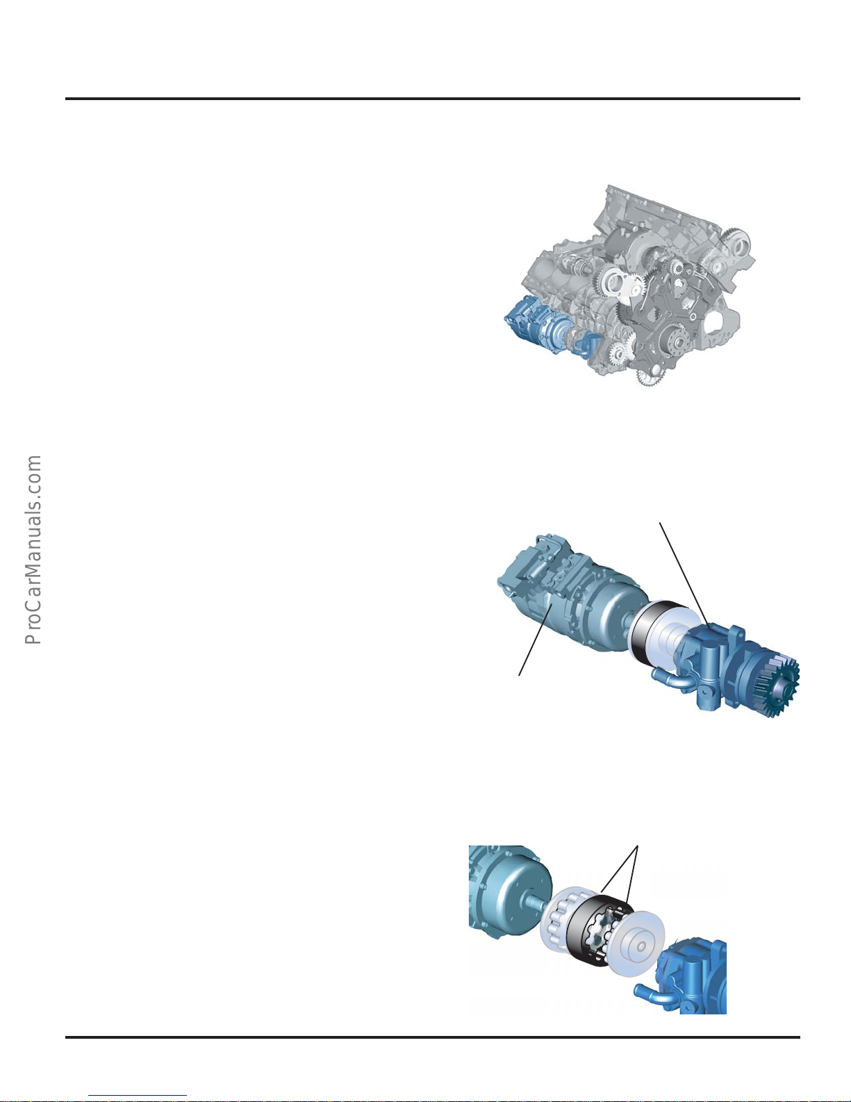
The power steering pump and the air
conditioning system compressor are arranged in
a row on the engine block. The power steering
pump is driven directly by the gear drive. The air
conditioning system compressor is driven by a
Gates® drive connected to the power steering
pump.
The overload protection of the air conditioning
system compressor is implemented by a
reinforced rubber element.
The Gates® drive consists of two metal drive
couplings with lugs that fit into a fabric
reinforced rubber sleeve. The elasticity of the
sleeve compensates for small shaft bending
angles and changes in length between the drive
couplings. It also provides a vibration
dampening effect for torque fluctuations.
Engine Mechanics
303_048
Power Steering Pump
Air Conditioning System
Compressor
303_072
Gates Drive
303_096
17
Page 22
Engine Mechanics
Oil Circulation
Oil Return Baffle
Vacuum Pump
Piston with
Cooling Channel
Oil Return Baffle
Oil Cooler
Bypass Valve
Oil Filter
Oil Return Baffle
Oil Pressure Switch
Exhaust
Turbocharger
Oil-Spraying Jets
(Piston Cooling)
Oil Separator
Return Oil
Pressurized Oil
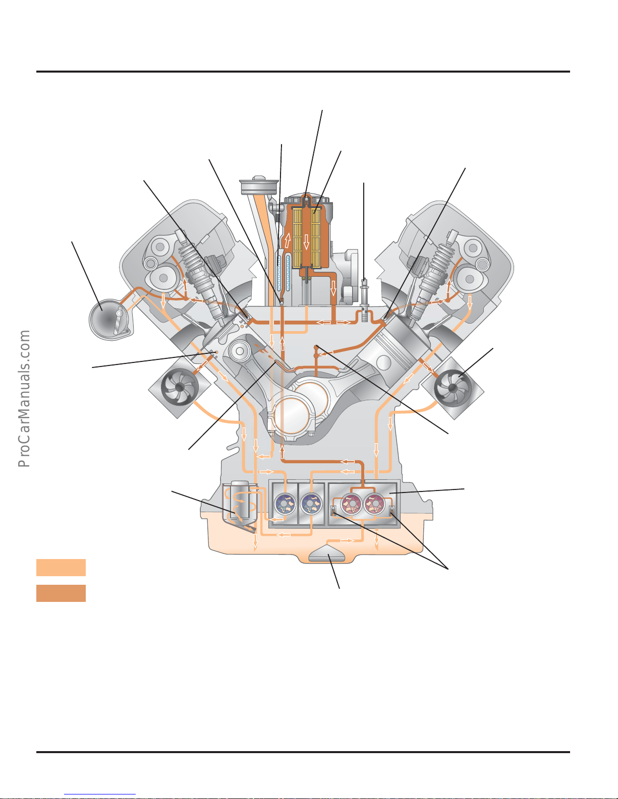
The Oil Pressure Control Valves control the oil
pressure of the engine. They open as soon as
the oil pressure reaches the maximum
permitted value.
The Oil Return Baffles prevent oil from flowing
back out of the cylinder head and the oil filter
housing into the oil pan when the engine is at a
standstill.
Belt Drive Module
Oil Supply
Oil Pump
303_053
Oil Pressure Control
Valves
Pickup Tube
The Bypass Valve opens when the oil filter is
restricted, thus ensuring the oil supply to the
engine (the oil filter is bypassed; the oil supply is
unfiltered when the bypass valve is open).
18
Page 23
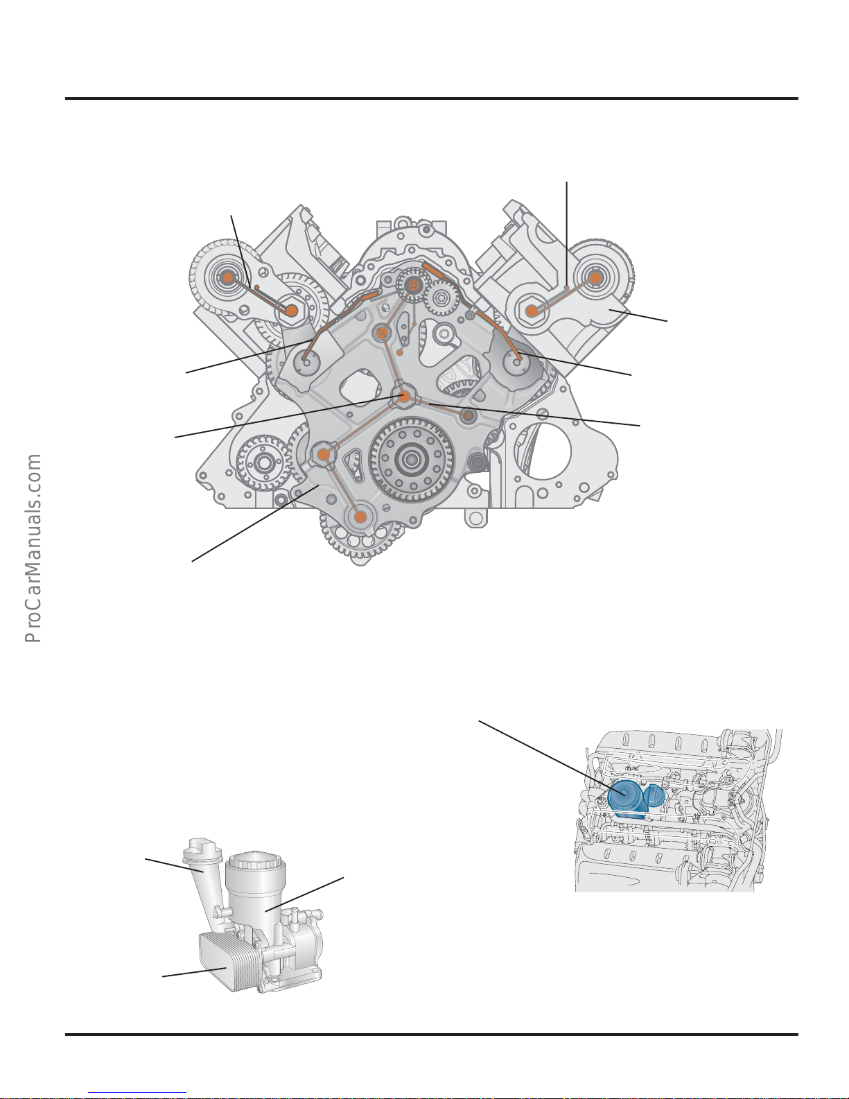
Engine Mechanics
Drive Module Oil Supply
Main Channel in
Cylinder Head
Oil Line
Oil Supply from
Cylinder Block
Main Channel in
Cylinder Head
Cylinder Head
Oil Line
Drive Module
Oil Channel
303_054
Drive Module
Oil Filter Module
The oil filter module is located in a space-saving
manner in the V-space of the engine. The oil
filters, the oil filler neck and the oil cooler are
integrated in the oil filter module.
Oil Filler
Neck
Oil Filter
Housing
Oil Filter Module
303_027
Oil Cooler
303_028
19
Page 24
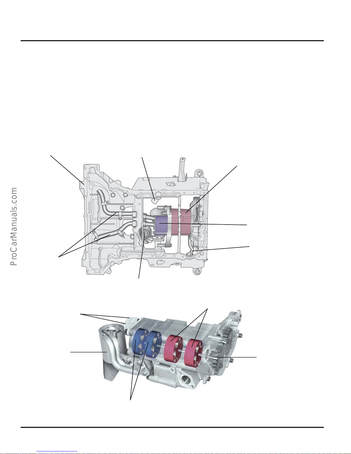
Engine Mechanics
Oil Pump
The oil pump is located in the upper portion of
the oil pan. It has oil pump rotors, that operate
according to the duo-centric principle. Two of
these are oil pressure pumps that generate the
oil pressure required for the oil circulation.
The other two are oil scavenge pumps that
Oil Pan, Upper Portion
Oil Return Pipe
return oil from the turbocharger oil returns to the
oil sump, ensuring that there is a sufficient
amount of oil in the sump in every operating
state.
The oil pump is gear-driven by the balancer
shaft.
Oil Pump
Oil Scavenge Pump
Oil Scavenge
Pumps Lines
Oil Scavenge Pump
Suction Lines
Oil Separator
Oil Pressure Line to Engine
303_093
Oil Separator
Oil Pump Rotors
Oil Pump Drive Gear
303_100
Oil Scavenge Pump
Rotors
20
Page 25
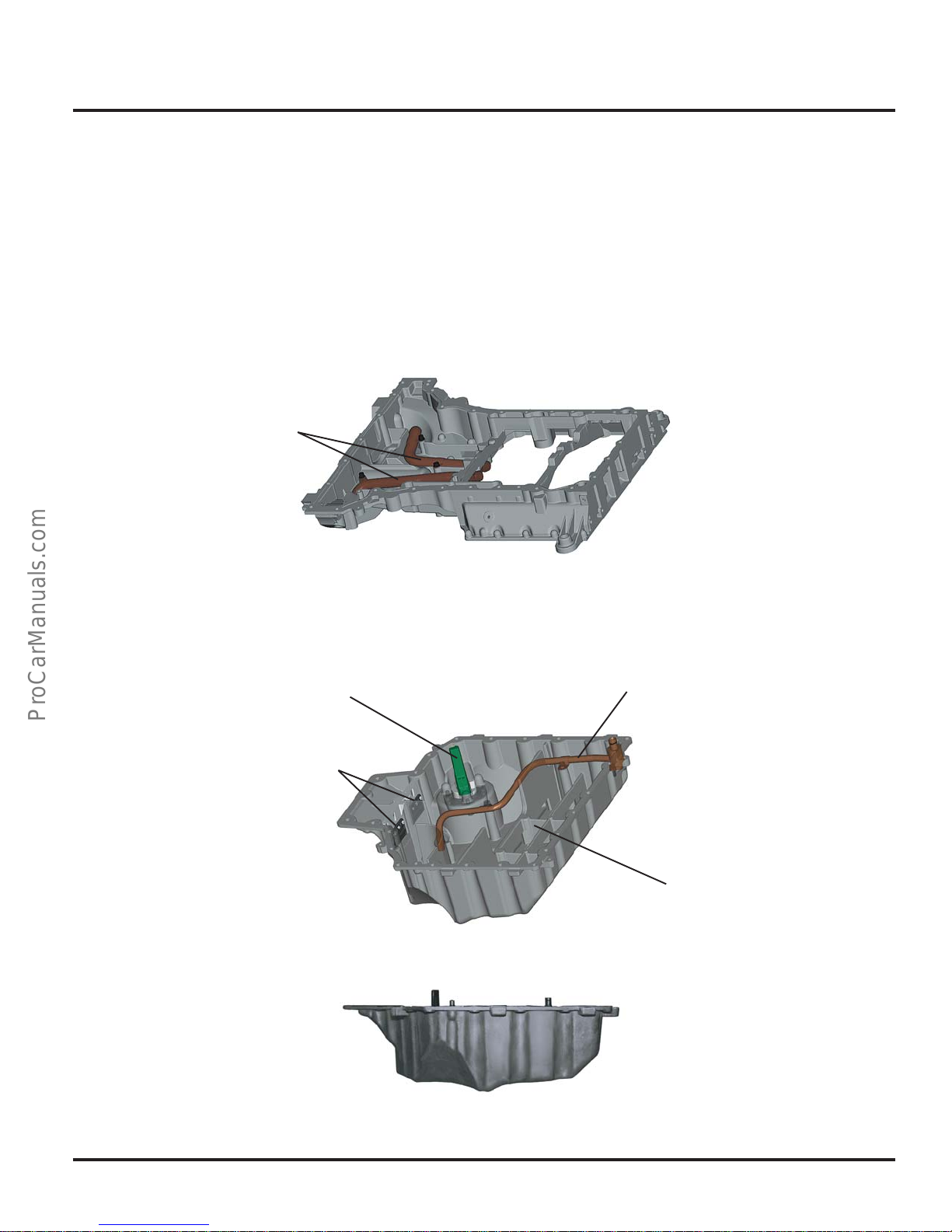
Oil Pan
Engine Mechanics
The oil pan consists of two cast-aluminium
parts.
The lines for the oil scavenge pumps are located
in the upper part of the oil pan. The lower part of
the oil pan contains the oil level sensor and the
wash plates that are used to calm the oil in the
oil sump.
Scavenge Pump
Oil Lines
Oil Pan, Upper Portion
The Touareg has a deep, lower part of the oil
pan, so it can hold a large amount of oil. In
addition, the lower part of the oil pan of the
Touareg has elastic flap traps. These prevent the
oil sump from running dry when driving on
inclines.
303_078
Oil Level Sensor
Elastic
Flap Traps
Oil Pan, Lower Portion
Oil Pipe to Oil
Scavenger
Wash Plates
303_080
303_081
21
Page 26
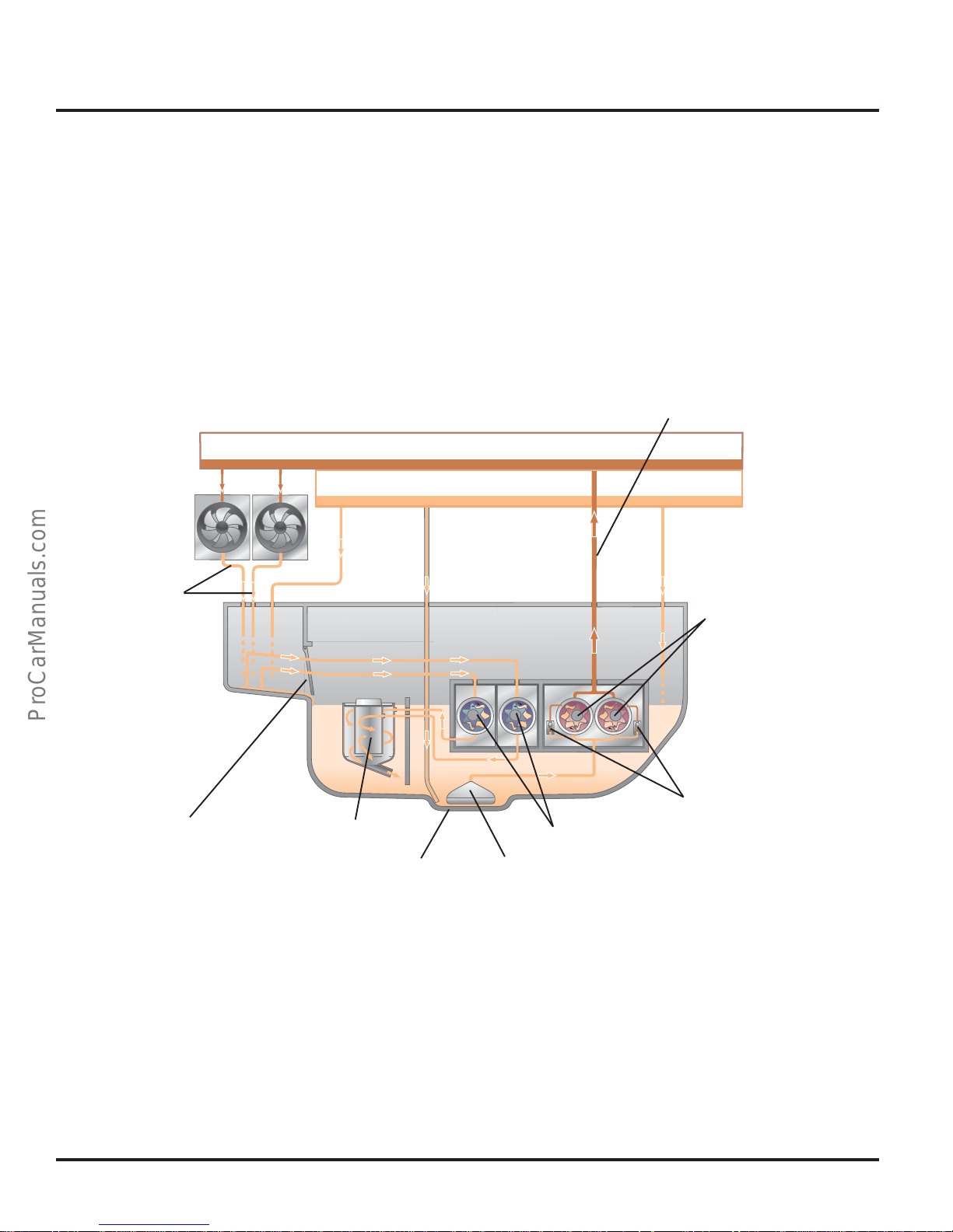
Engine Mechanics
Oil Scavenge System
Two oil scavenge pumps are used to ensure an
ample supply of oil in the sump in all driving
conditions.
The following examples describe the oil
scavenge system in three different driving
states.
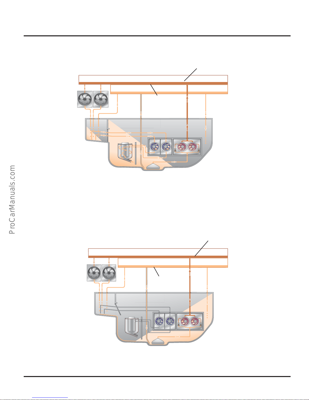
Pressurized
Oil Channel
Oil Return
Auxiliary
Turbocharger
Oil Return
Drive Oil
Return
Flap Traps
During uniform, level driving, the two oil
pressure pumps suction the oil from the oil
sump through the pickup tube and pump it into
the pressurized oil system of the engine. Part of
the returning oil flows directly into the oil sump
of the oil pan while the rest flows from the
returns of the turbocharger and auxiliary drive
into the rear area of the oil pan.
Oil Separator
Sump
Oil Return
Oil Scavenge Pumps
Pickup Tube
Oil
Return
Oil Pressure Pumps
Oil Level Normal Operation
Oil Pressure
Control Valves
303_019
There, the oil is suctioned off by oil scavenge
pumps and returned to the oil sump by the oil
separator.
The oil separator works according to the
principle of a cyclone. It separates the oil from
the scavenged oil-air mixture before the oil
flows back to the oil sump.
22
Page 27
Oil Scavenge System, Uphill Driving
Engine Mechanics
Pressurized Oil System
Oil Return
303_020
During uphill driving or when accelerating, the oil flows into the rear area of the oil pan. The flap
traps close, preventing the oil from flowing into the rear area of the oil pan. The oil scavenge pumps
suction the oil out of the rear area of the oil pan, eliminating backpressure from the turbocharger
and the auxiliary drive oil return. This oil is then routed to the oil separator.
The oil separator removes air from the oil. The air-free oil drains into the sump, ensuring ample oil
supply to the oil pressure pumps.
Oil Scavenge System, Downhill Driving
Oil Return
Pressurized Oil System
During downhill driving or braking, the oil collects in the front part of the oil pan. As a result, the oil
level lies above the pickup tube, ensuring ample oil supply to the oil pressure pumps. The return oil
from the turbocharger and auxiliary drive flows into the oil sump through the open flap traps.
303_021
23
Page 28
Engine Mechanics
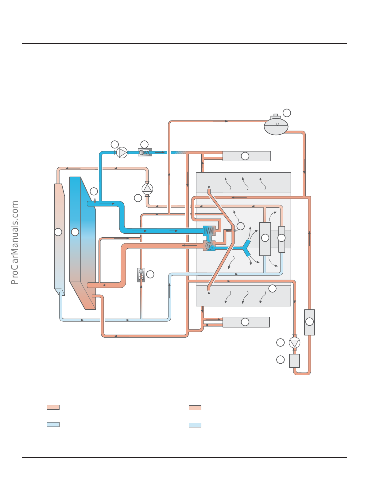
Coolant Circulation System
System Overview
10
16
12
3
4
14
5
15
9
8
6
7
14
13
Engine Coolant Circulation
Warm
Cold
24
11
12
Coolant Circulation for Alternator and
Fuel Cooling (Touareg Only)
Warm
Cold
303_039
Page 29
Engine Mechanics
1. Cooler for Engine Coolant Circulation
2. Cooler for Alternator/Fuel Cooling
3. Pump for Coolant After-run V51
4. Check Valve
5. Pump for Fuel Cooling V166
6. Valve Body
7. Cylinder Head/Cylinder Block
8. Generator (Alternator)
Coolant Circulation for Alternator and Fuel
Cooling
In the Touareg, the V10-TDI engine has a
separate coolant circulation for the alternator
and the fuel cooling. This is required because
the temperature of the coolant is too high to
cool the returning fuel when the motor is
running.
Pump for Coolant After-run V51
The pump for coolant after-run is an electrically
driven pump that is activated by the Engine
Control Module (ECM).
It fulfills two duties:
1. At low engine speeds, the pump for coolant
after-run supports the mechanically-driven
coolant pump, thus providing for sufficient
coolant circulation.
2. To carry out the coolant after-run function,
the pump is activated by the ECM according
to a characteristic map.
9. Fuel Cooler
10. Compensator Reservoir
11. Recirculation Pump V55
12.Heater Core for Heater
13.Auxiliary Water Heater (Auxiliary Heater)
14.Cooler for Exhaust Return (Phaeton only)
15.Engine Coolant Temperature (ECT) Sensor
G62
16.Coolant Temperature Sensor - Radiator
Outlet G83
Recirculation Pump V55
The fuel cooling pump is an electrical circulation
pump. If required, it is activated by the
Climatronic control unit, providing coolant
circulation for the alternator and the fuel cooling.
1. When the engine is running, the pump
provides an increased flow of coolant
through the heater core for the heater; it also
supports the functioning of the auxiliary
heater.
2. The pump fulfills the duties of the residual
heat function up until 30 minutes after the
engine is stopped. For this purpose, it is
activated by the Climatronic control unit
when the driver activates the residual heat
function.
Pump for Fuel Cooling V166
The fuel cooling pump is an electrical circulation
pump. If required, it is activated by the ECM,
providing coolant circulation for the alternator
and the fuel cooling.
25
Page 30
Engine Mechanics
303_047
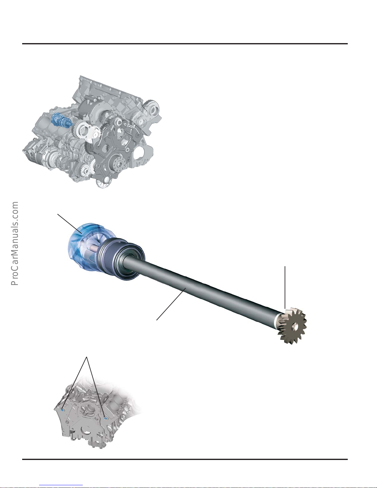
Coolant Pump
Coolant Pump
The coolant pump is located on the front of the
engine block. It is driven by the belt drive
module by a connection shaft.
Coolant Drain Plugs
Drive Gear in
Drive Module
Connection
Shaft
303_075
Coolant Drain Plugs
Two coolant drain plugs are located on the
engine face in the cylinder block. When the
cylinder heads or another component in the
V-space of the engine is removed, the coolant
drain plugs can be used to drain the coolant
down to the level of the coolant pump.
26
303_076
Page 31
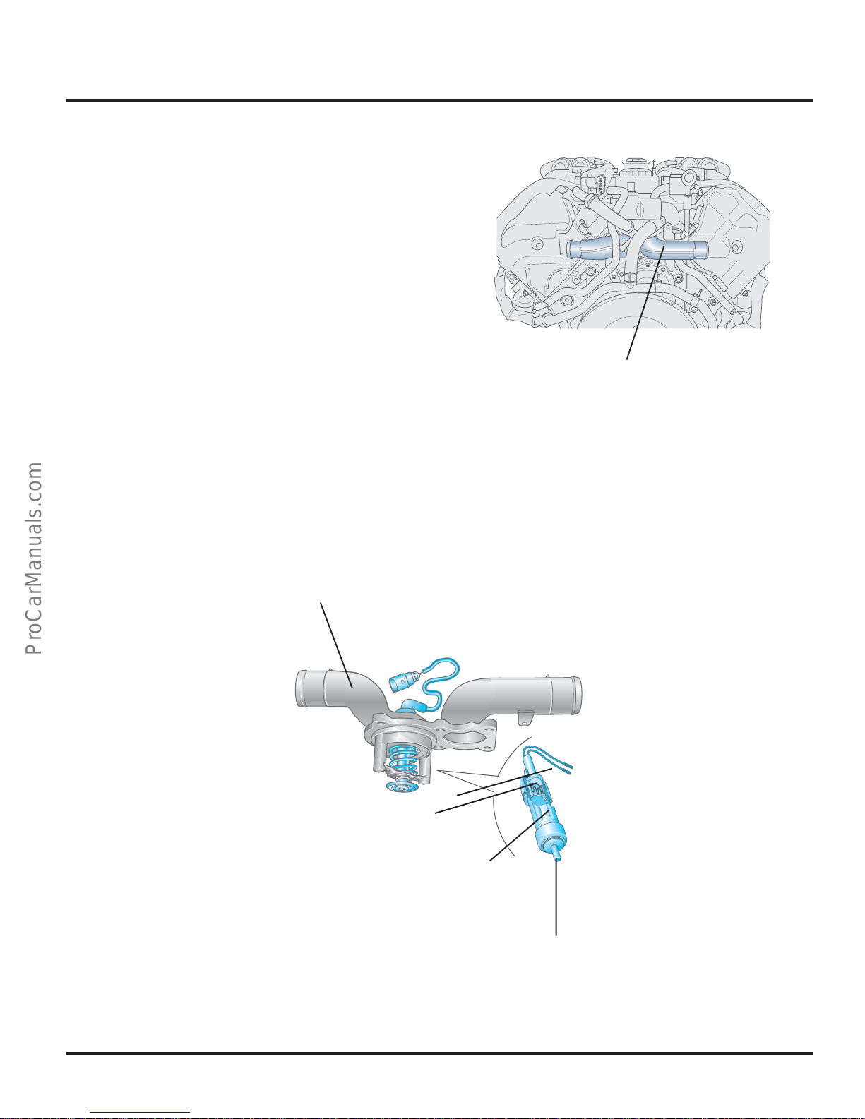
Thermostat for Map-Controlled Engine
Cooling
The thermostat for map-controlled engine
cooling is located in the pipe union of the
coolant controller housing. It switches between
the large and the small coolant circulation
systems. For this, it is activated by the ECM
according to the requirements of the engine’s
operating state. Characteristic maps that contain
the nominal value temperature, depending on
the engine load, are stored in the ECM.
The advantage of characteristic map-controlled
engine cooling is that the coolant temperature
level can be adapted to the current operating
state of the engine. This helps to reduce fuel
consumption in the partial-load range and to
reduce exhaust emissions.
Engine Mechanics
303_026
Pipe Unions of
Coolant Controller
Housing
Pipe Unions of
Coolant Controller
Housing
Compression
Spring
Resistance
Heating
Elastic Element
Stroke Pin
303_015
27
Page 32
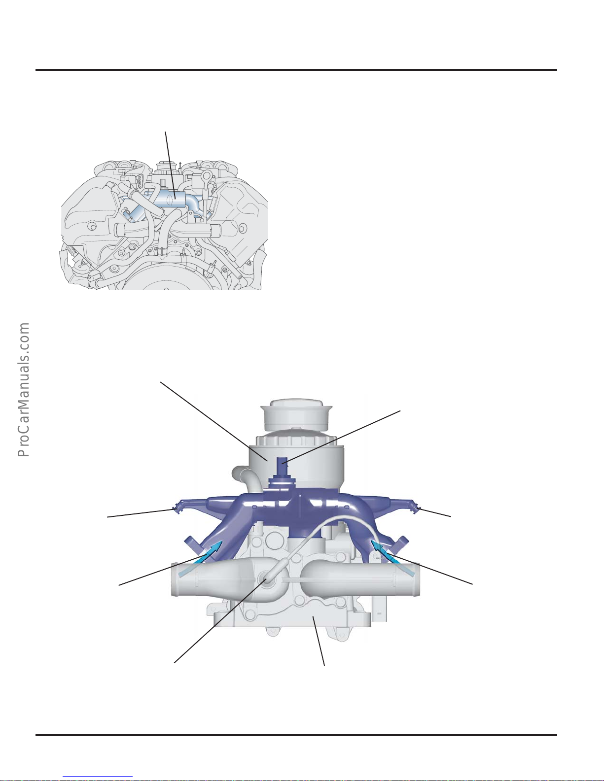
Engine Mechanics
Water Connection
Coolant Connection
Oil Filter
The water connection is located in the V-space
of the engine, above the coolant controller
housing.
It connects the coolant circulation of the two
cylinder heads. The coolant is transported out of
the cylinder heads through the two large
connections to the coolant controller housing.
The topmost small connections are used for
ventilation.
303_012
Coolant
Temperature
Sensor G62
Ventilation
Connection
Coolant
Connection
Connection Nozzle
Ventilation
Connection
Coolant
Connection
303_014
Coolant Controller
Housing
28
Page 33
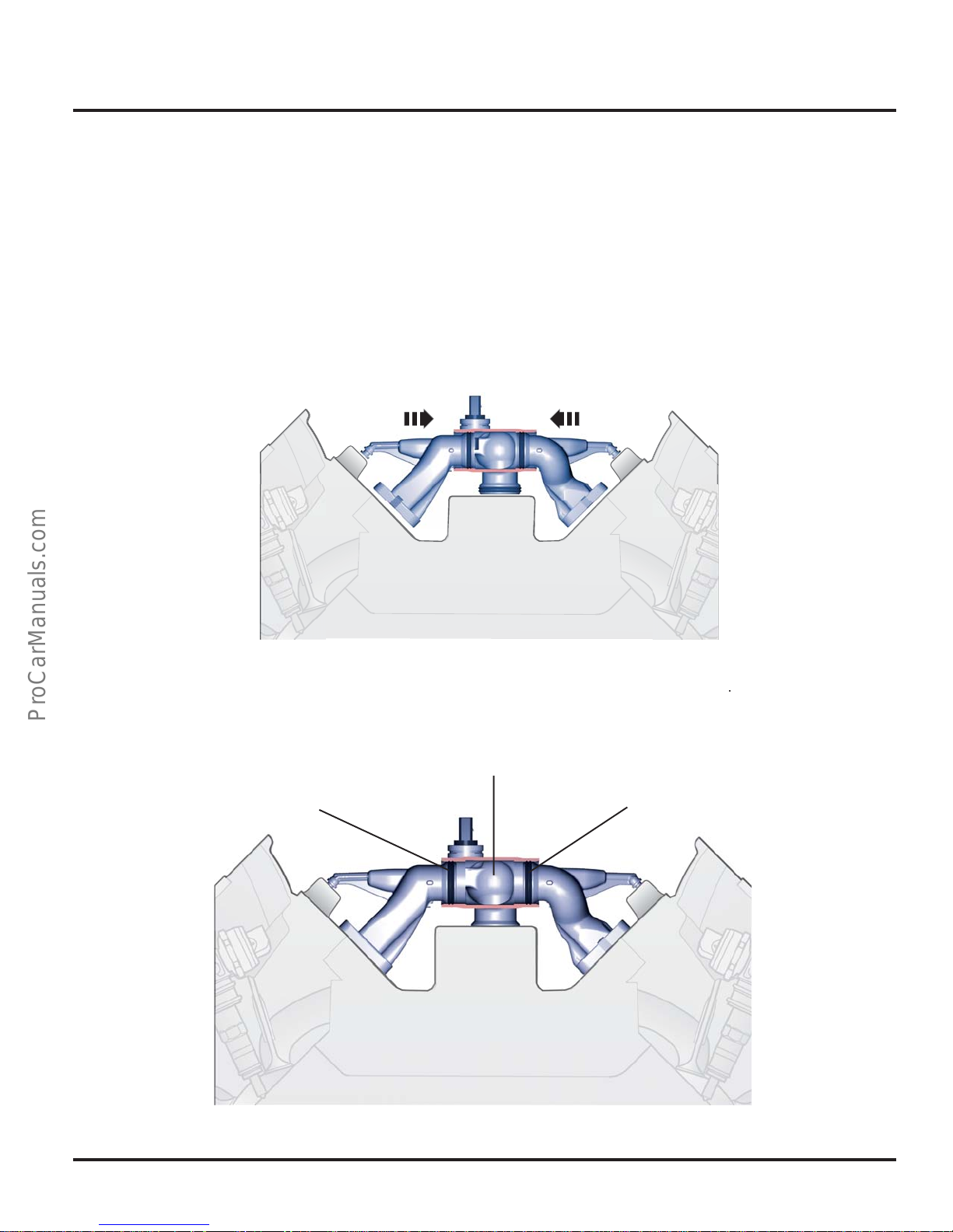
Removal and Installation
To permit the coolant connection in the V-space
of the engine to be removed and installed, the
two large connections in the coolant connection
housing can be pushed in/pulled apart.
Coolant Connection - Assembly Position
Engine Mechanics
Coolant Connection - Installed Position
Gasket
Coolant Connection Housing
Gasket
303_105
303_013
29
Page 34
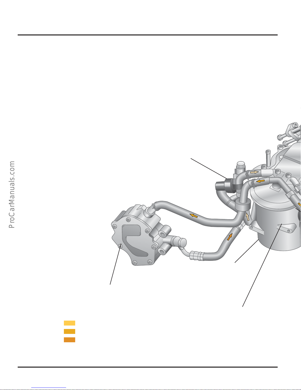
Engine Mechanics
Fuel System
The fuel is transported out of the fuel tank to
the fuel filter unit by electrical fuel pumps. The
mechanical fuel pumps suck the fuel out of the
fuel filter unit and transport it at high pressure
into the preliminary run of the fuel rails.
The fuel not required for fuel injection is
returned to the tank through the return fuel rails,
fuel filter, and fuel cooler.
Fuel Temperature Sensor
Fuel
Filter
Fuel Pump
Fuel Temperature Sensor
Return Flow
Preliminary Run - Low Pressure
Preliminary Run - High Pressure
30
Page 35
Fuel Cooler
Engine Mechanics
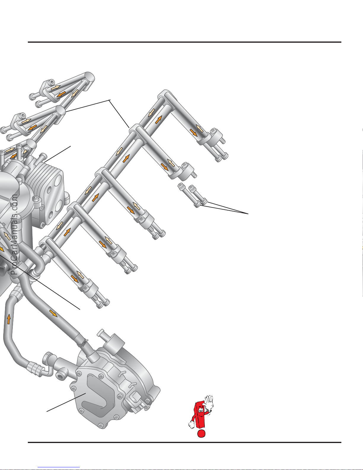
Fuel Manifold
Fuel Return Pressure Relief Valve
Connection Nozzle
Vacuum Pump
Fuel Pump
303_051
In the Touareg, the fuel is cooled by a fuelto-coolant cooler.
31
Page 36
Engine Mechanics
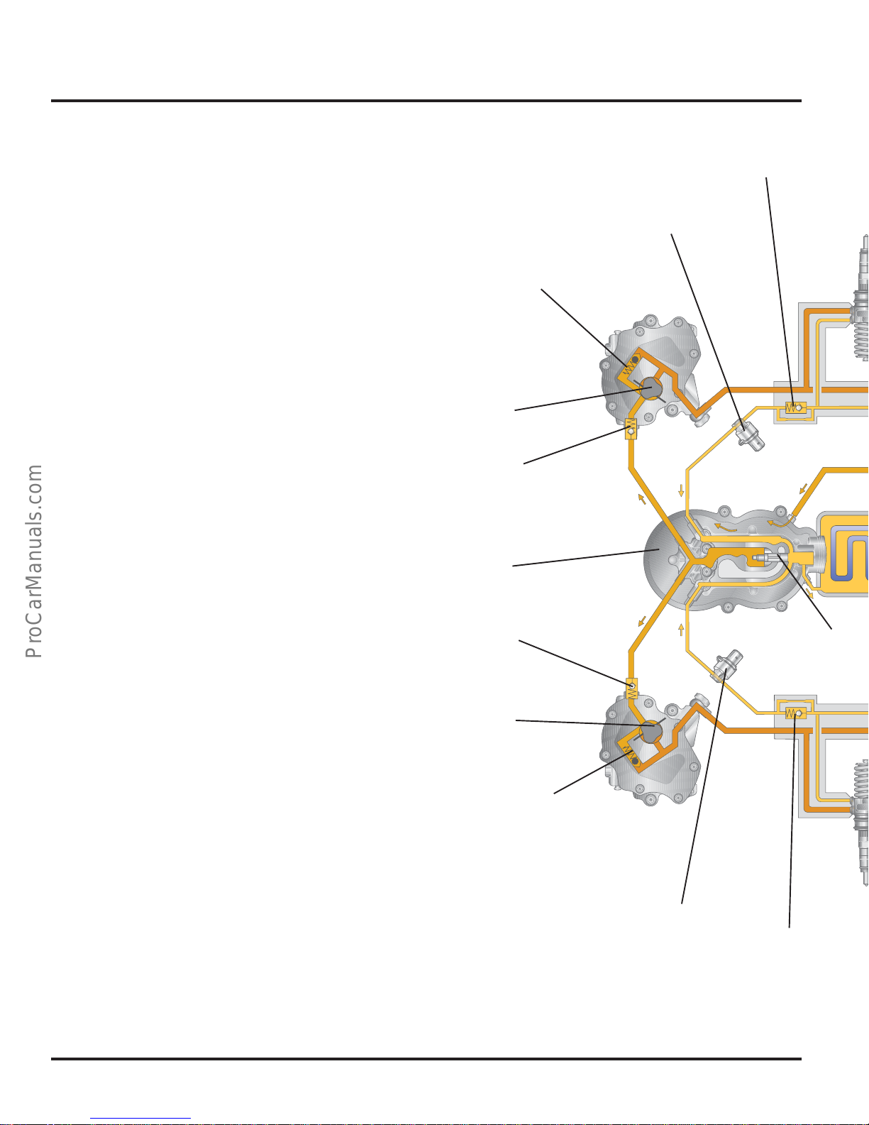
Overall Schematic Diagram
The Electrical Fuel Pumps work as preliminary
transport pumps, pumping fuel to the fuel filter
unit.
The Check Valves prevent fuel in the fuel
manifold and the preliminary run line from
flowing back into the fuel tank when the engine
is at a standstill.
The Fuel Filter Unit protects the injection
system from excessive wear by removing dirt
and water.
The Fuel Pumps transport the fuel out of the
fuel filter unit and pump it at high pressure into
the preliminary run of the fuel rails.
Fuel Return
Pressure Relief Valve
Fuel
Temperature
Sensor
Pressure Control
Valve
Fuel Pump
Check Valve
The Pressure Control Valves regulate the fuel
pressure in the fuel preliminary run to
approximately 8.5 bar.
The Pressure Relief Valves limit the fuel
pressure in the fuel return flow to approximately
1 bar. As a result, the pressure conditions in the
fuel system are balanced.
The Fuel Temperature Sensors are used to
record the fuel temperature for the ECMs.
The Preheating Valve guides the fuel in the
return flow into the fuel filter unit when the
outside temperature is low, thus preventing
clogging of the filter inserts.
The Fuel Cooler cools the fuel in the return flow
to protect the fuel tank from fuel that is too hot.
Fuel Filter
Unit
Check Valve
Fuel Pump
Pressure Control
Valve
Fuel Temperature
Sensor
Preheating Valve
Fuel Return
Pressure Relief
Valve
32
Page 37
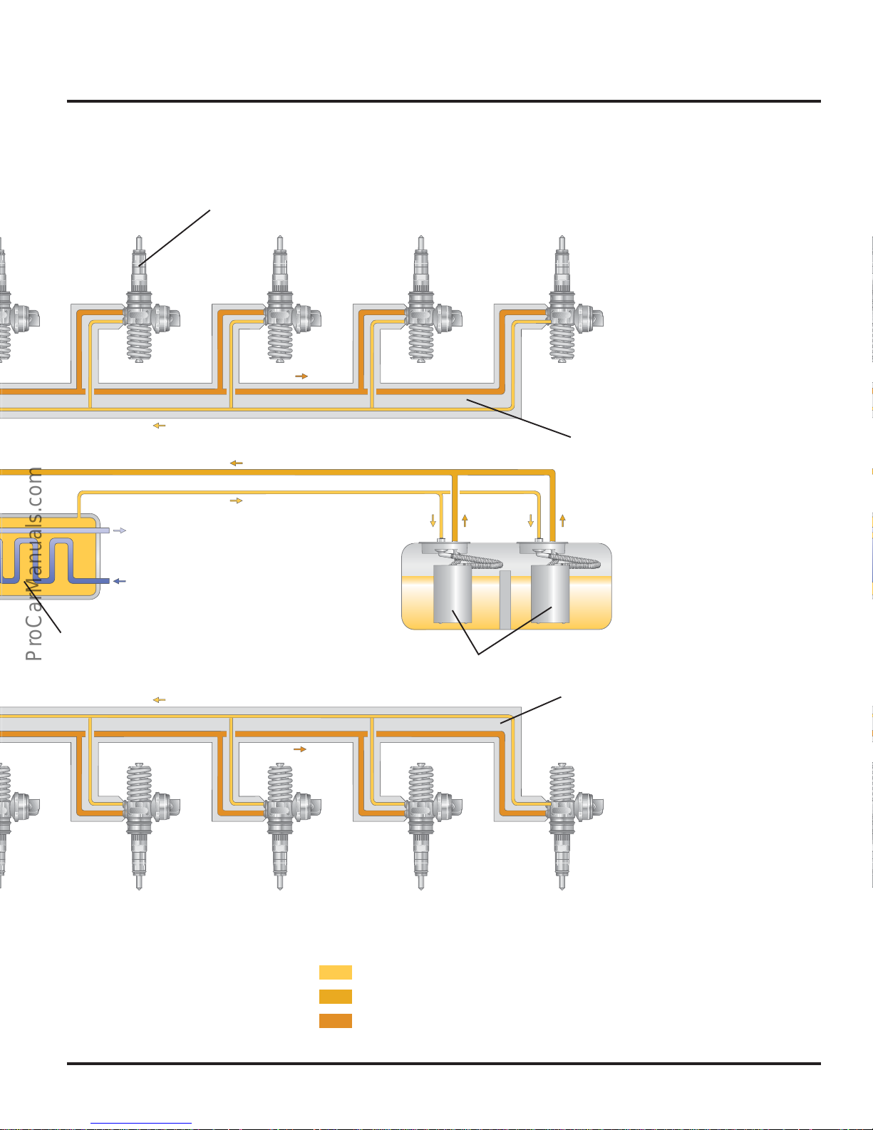
Pump - Injector Unit
Engine Mechanics
Fuel Manifold
Coolant
Fuel Cooler
Electric Fuel Pump
Fuel Manifold
303_088
Return
Preliminary Run - Low pressure
Preliminary Run - High pressure
33
Page 38
Engine Mechanics
Fuel Filter
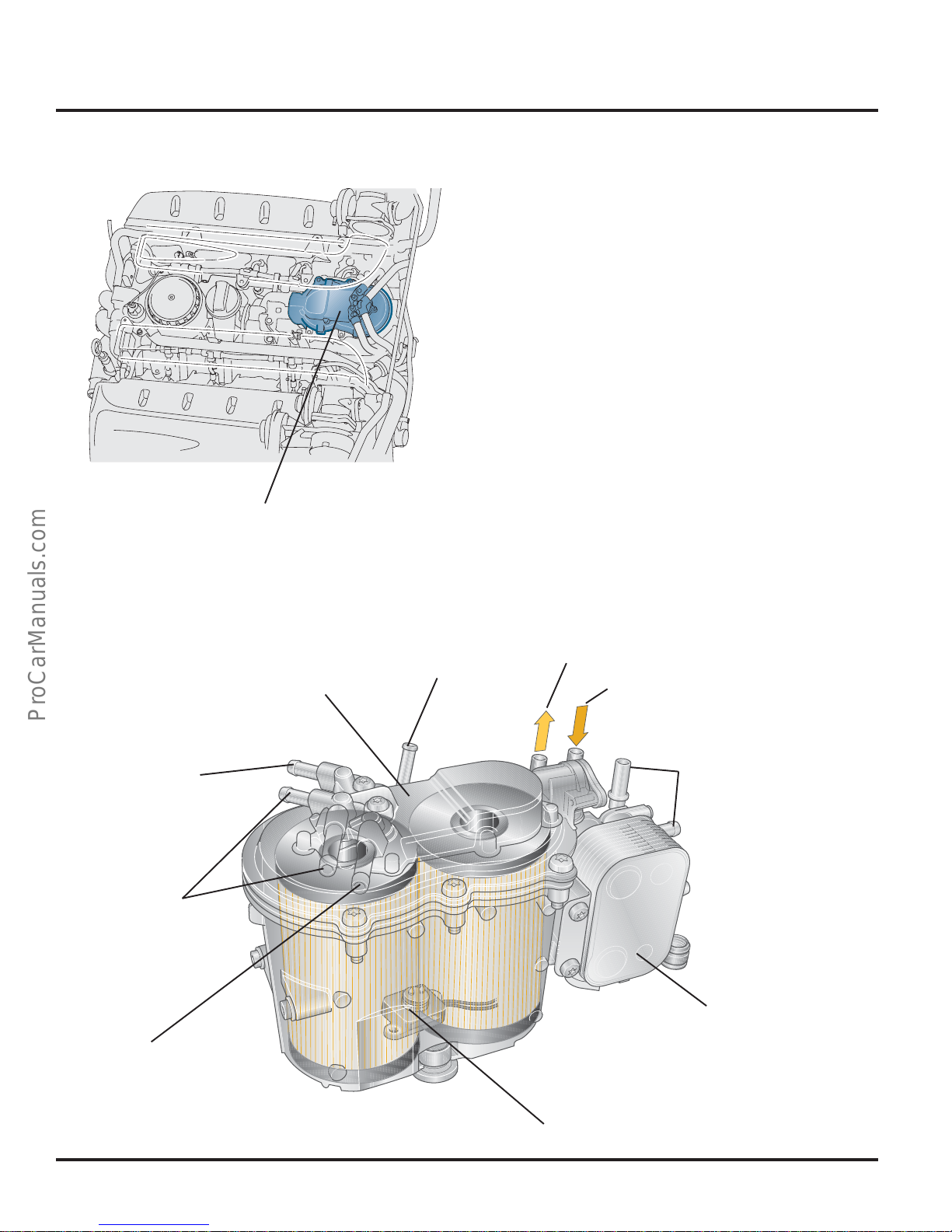
Unit
303_029
Fuel Filter Unit
The fuel filter unit is located in a crash-safe
position in the V-space of the engine. It contains
two filter inserts and a sensor for the fuel
contamination. The sensor for the fuel
contamination is used to inform the driver if the
water level in the filter unit is too high, using an
indicator light in the dash panel insert.
There is a preheating valve in the lid of the fuel
filter unit; when the outside temperature is low,
this guides the fuel in the return flow from the
engine back into the filter. In the Touareg, a
coolant-fuel cooler is integrated into the fuel
filter unit. It cools the fuel flowing back into the
fuel tank, thus preventing damage to the fuel
tank by return flow fuel that is too hot.
Fuel Return from the
Pump-Jet Units
Fuel Preliminary
Run to Fuel Pump
Fuel Return from the
Pump-Jet Units
Fuel Filter Lid
Drainage
Return Flow to Fuel Tank
Preliminary Run of Fuel Tank
Coolant Connection
Fuel Cooler
303_030
34
Fuel Contamination Sensor
Page 39
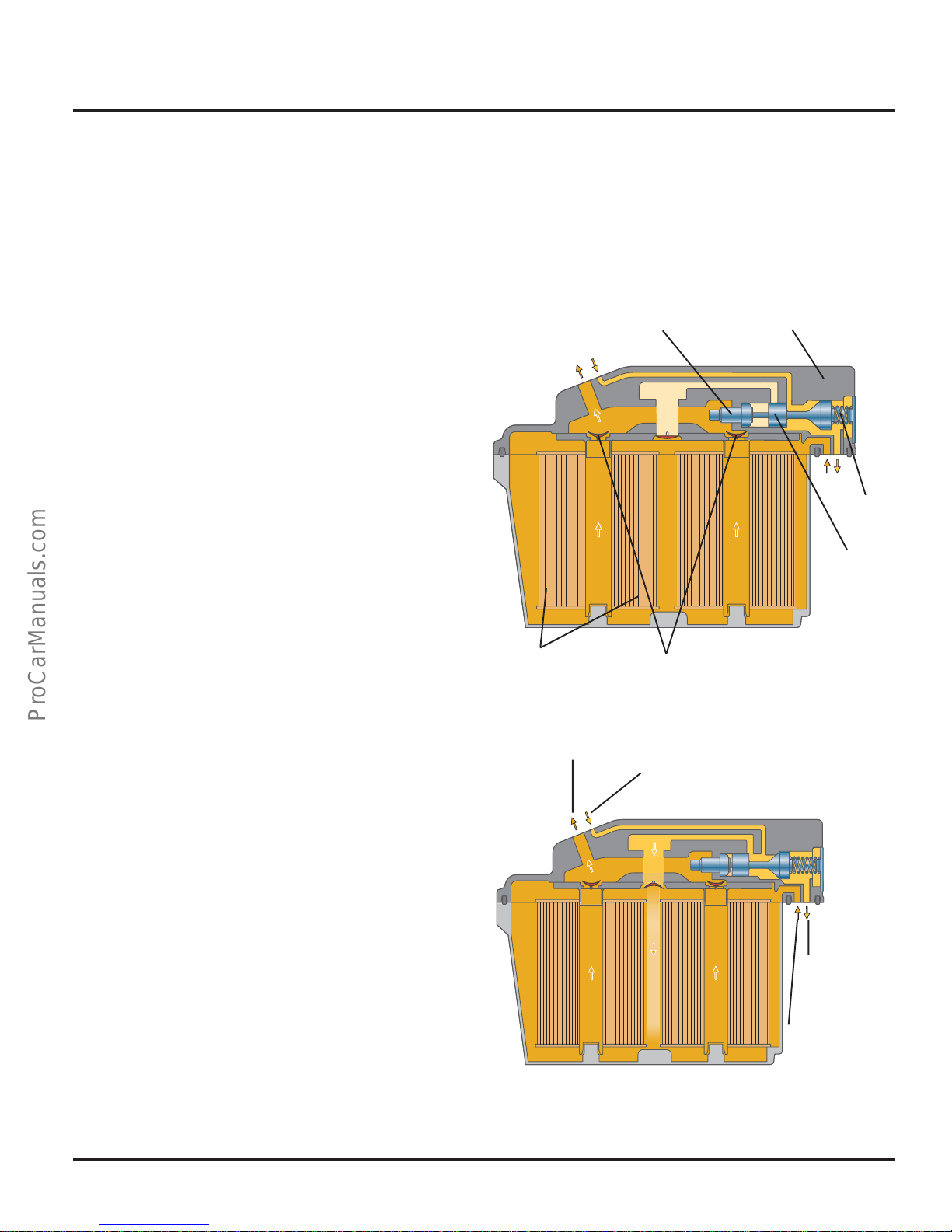
Preheating Valve
At low outside temperatures, diesel fuel tends
to thicken. This can clog the fuel filter; as a
result, operating the engine may no longer be
possible due to a lack of fuel.
Engine Mechanics
Warm Fuel Temperature
At a fuel temperature above 104°F (40°C) in the
fuel preliminary run, the piston is pressed
against the spring by the elastic element. The
preheating valve completely opens the way into
the fuel return flow. The fuel that is flowing back
from the pump-jet units directly enters the
return flow to the fuel tank.
In the fuel preliminary run, the fuel is
transported via filter inserts and the flapper
valve to the fuel pumps.
Cold Fuel Temperature
At a fuel temperature below 50°F (10°C), the
elastic element contracts, so that the spring
force of the piston closes the way to the fuel
tank. As a result, the fuel that is flowing back
from the pump-jet units is guided to the filters.
The fuel in the filter unit is heated, thus
preventing clogging of the filters.
Depending on the outside temperature, the
preheating valve guides the fuel that is flowing
back from the pump-jet units either to the fuel
filters or to the fuel tank.
Warm
Filter
Cold
Elastic Element
Flapper
Valve
To Fuel
Pump
Lid of Fuel Filter
Unit
Spring
Piston
303_103
Return Flow from
Pump-Jet Units
Return
Flow to
Fuel Tank
Preliminary Run
of Fuel Tank
303_104
35
Page 40
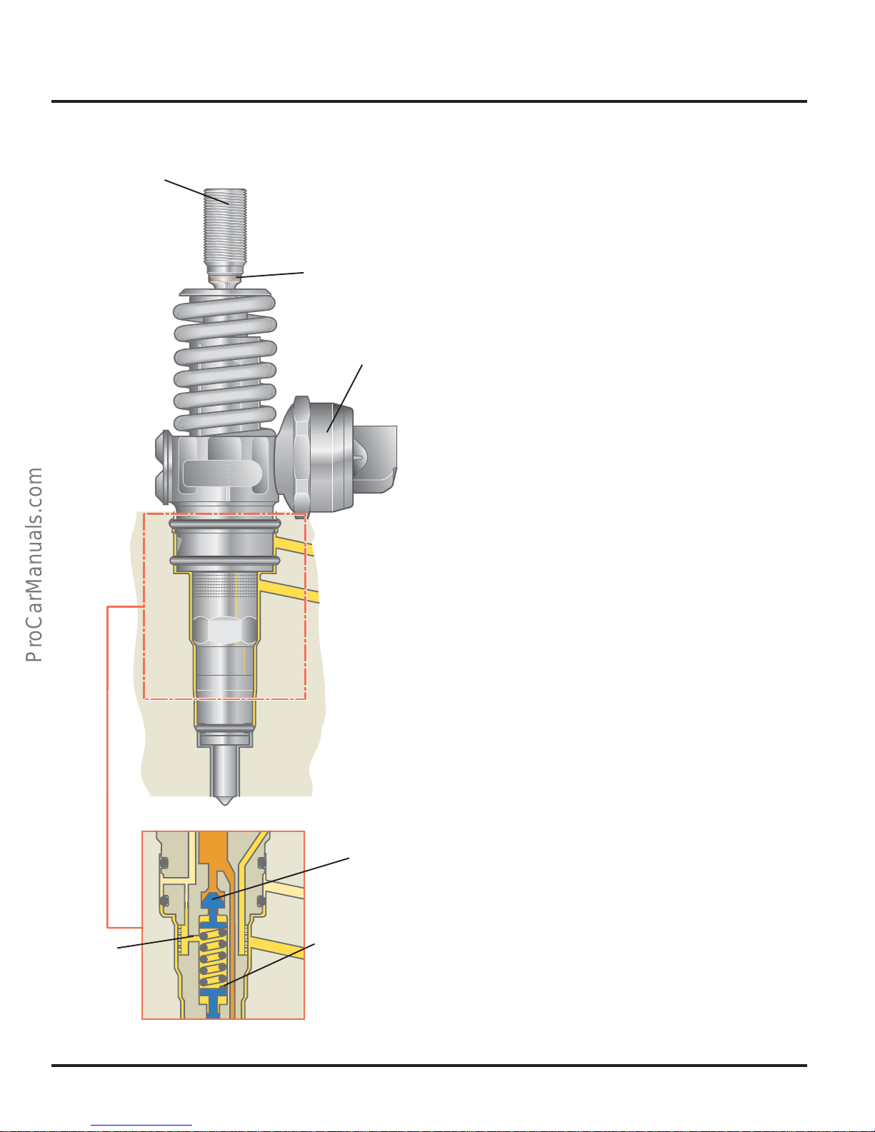
Engine Mechanics
Adjusting Screw
Stud
Solenoid
Valve
Pump-Injector Units
The same type pump-injector units used in the
1.9l/74 kW TDI engine are also used in the
V10-TDI engine.
They are characterized by:
• A low-friction drive
• An increased injection pressure in the
partial load range
• A compact solenoid valve
To provide a low-friction drive, the adjusting
screw is equipped with a rounded end while the
stud is provided with a ball socket. Due to the
large radius, the surface pressure is low. In
addition, the engine oil can collect in the ball
socket, thus ensuring good lubrication between
the adjusting screw and the stud.
In the partial load range, the injection pressure
is increased by an alternative piston with a large
stroke. Due to the large stroke of the alternative
piston and the throttling effect of the inlet port
between the jet spring space and the fuel
channel, the pressure in the jet spring space
increases. The jet springs are further
prestressed, thus increasing the injection
pressure.
Inlet Port
303_010
36
Alternative
Piston
Jet Spring
Page 41
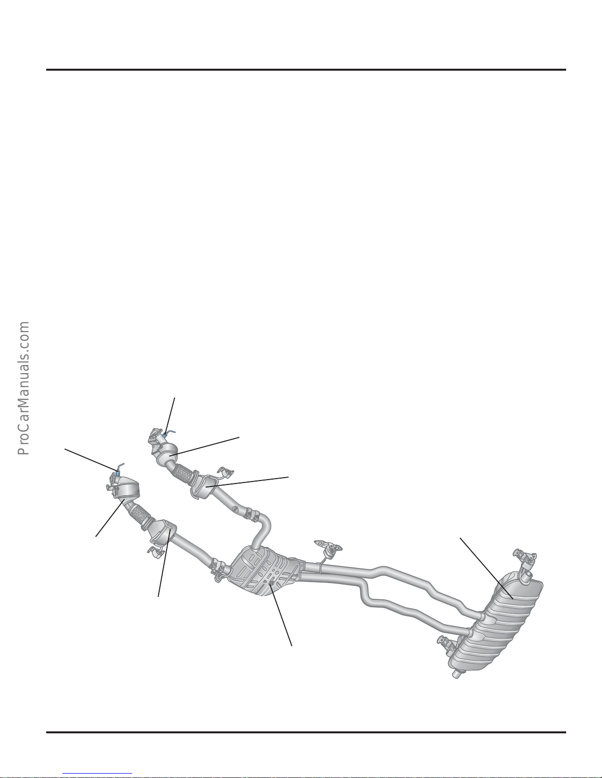
Exhaust System
The all-stainless steel exhaust system of the
V10-TDI engine consists of one preliminary
catalytic converter and one main catalytic
converter per cylinder bank, as well as a
preliminary silencer and a main silencer.
All catalytic converters are oxidation catalytic
converters.
The preliminary catalytic converters are located
near the engine so operating temperature can
be quickly attained, ensuring a high degree of
pollutant reduction. The oxygen sensors located
in front of the preliminary catalytic converters
are used to control exhaust gas recirculation.
Engine Mechanics
O2 Sensor
O2 Sensor
Preliminary
Catalytic Converter
Main Catalytic
Converter
Preliminary Catalytic Converter
Main Catalytic
Converter
Rear Silencer
Preliminary Silencer
303_033
37
Page 42
Engine Mechanics
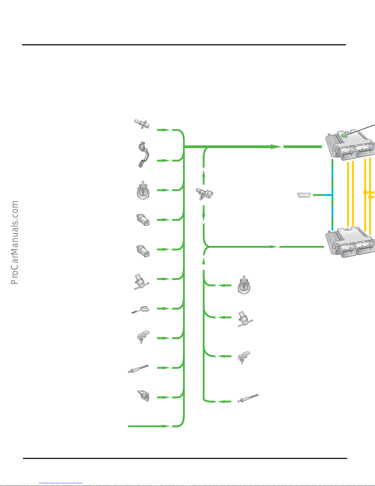
Overview of Engine Management
This section provides you with an overview of
the V10-TDI engine management system. A
detailed description of the sensors, actuators
Engine Speed Sensor G28
Throttle Position (TP) Sensor G79
Kickdown Switch F8
Closed Throttle Position (TP) Switch F60
Mass Air Flow (MAF) Sensor G70
Engine Coolant Temperature
(ECT) Sensor G62
Engine Coolant Temperature Sensor
(ECT) on Radiator G83
and functions of engine management can be
found in Self-Study Program 89P303,” Touareg
Electronic Diesel Control EDC 16.
Engine Control
Module (ECM) J623
Camshaft Position
(CMP) Sensor G40
Diagnostic
Connecto
Module (ECM) 2 J624
r
Engine Control
Intake Air Temperature (IAT) Sensor G42
Fuel Temperature Sensor G81
Fuel Contamination Sensor G133
Charge Air Pressure Sensor G31
Oxygen Sensor (O
Brake Light Switch F63
Brake Pedal Switch F47
Additional Input Signals
S) G39
2
Mass Airflow (MAF)
2 G246 Sensor
Fuel Temperature Sensor 2
G248
Intake Air Temperature (IAT)
Sensor 2 G299
Charge Air Pressure Sensor
2 G447
Oxygen Sensor (O2S) 2 G108
38
Page 43
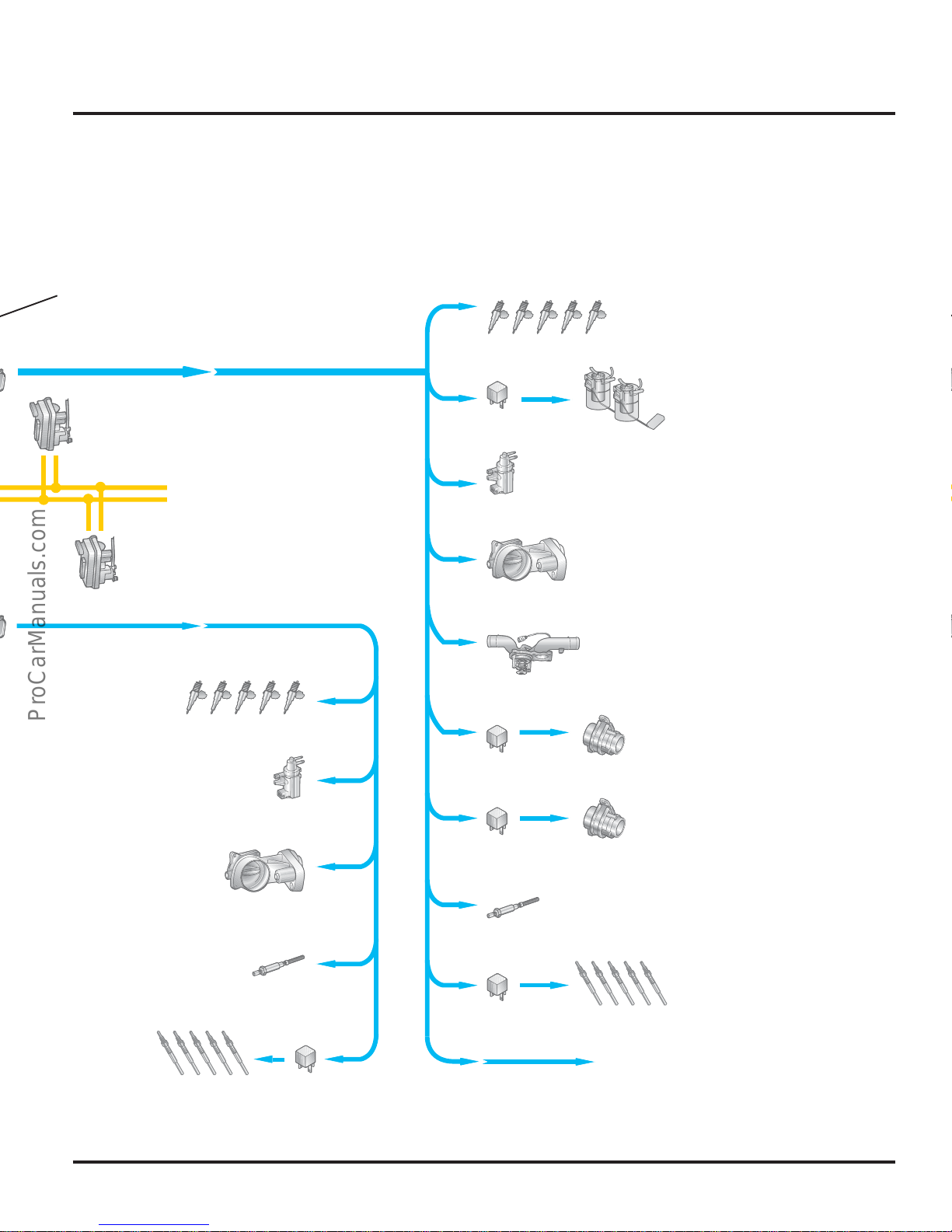
Engine Mechanics
Altitude Sensor
Turbocharger 1 Servo-Motor V280
Turbocharger 2 Servo-Motor V281
Valve for Pump
Injector N245,
N303-N306
Valve for Pump Injector N240N244
Fuel Pump (FP) Relay J17
Fuel Pump (FP) G6
Transfer Fuel Pump (FP) G23
EGR Vacuum Regulator Solenoid
Valve N18
Motor for Intake Flap V157
MAP Controlled Engine Cooling
Thermostat F265
Auxiliary Engine Coolant Pump
Relay J496
Water Pump V51
Valve 2 for EGR N213
Intake Flap Motor
2 V275
Oxygen Sensor (O
Heater 2 Z28
Glow Plug
Relay 2 J495
Glow Plugs
Q15-Q19
S)
2
303_036
Relay for Pump, Fuel Cooling J445
Pump for Fuel Cooler V166
Oxygen Sensor (O
Glow Plug Relay J52
Glow Plug Q10-Q14
Additional Output Signals
S) Heater Z19
2
39
Page 44
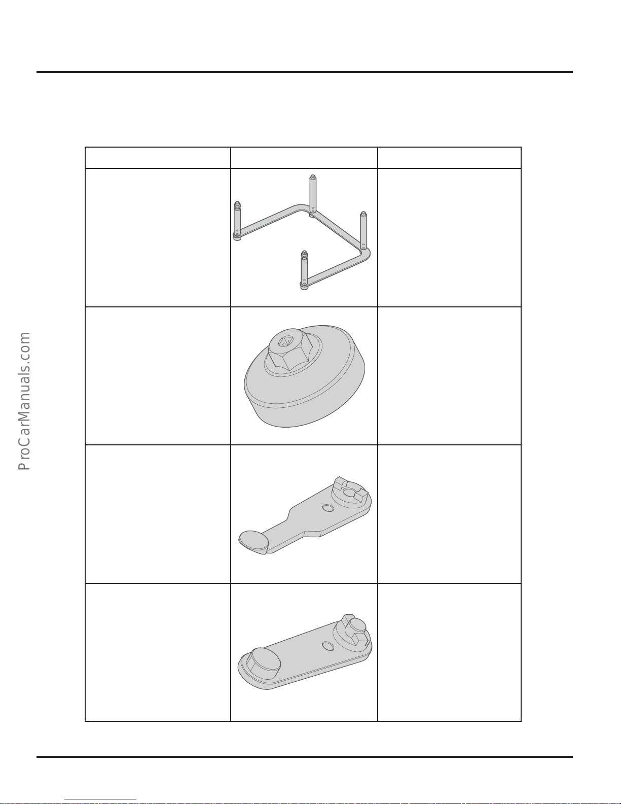
Service
Service
Designation Tool
T10191
Frame
T10192
Oil Filter Key
Usage
To switch off
the V10-TDI
engine
303_056
Removal and
installation of the oil
filter lid
303_057
T10193
Camshaft Clamp
T10194
Camshaft Clamp
To fasten the
camshaft cylinder
bank 1 when setting
the control times
303_058
To fasten the
camshaft cylinder
bank 2 when
setting the
control times
Removal and
installation of the
oil filter module
303_059
40
Page 45
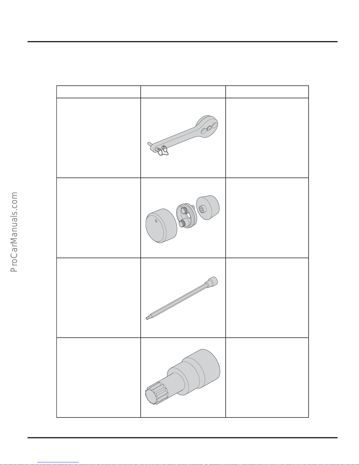
Designation Tool Usage
Service
Service
T10195
Crankshaft Clamp
T10196
Key
T10197
Plug Cartridge SW6
To fasten the crankshaft
when setting the
control times
303_061
To install the PTFE
crankshaft gasket on
the flywheel side
303_061
For removal and
installation of various
add-on pieces in the
V-space of the engine
T10198
Plug Cartridge XZN16
303_062
303_063
For removal and
installation of the
camshaft wheel
41
Page 46
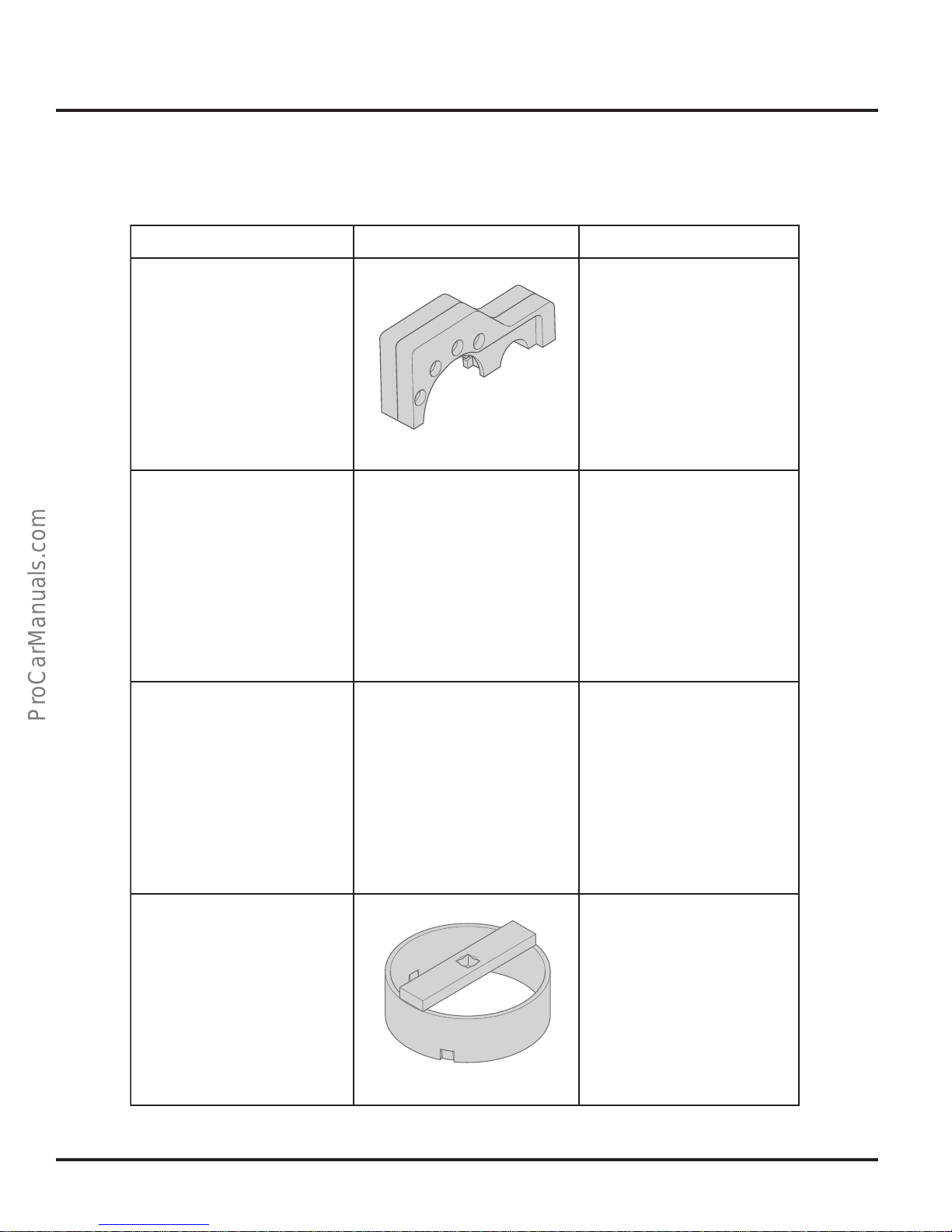
Service
Service
Designation Tool
T10199
Clamping Device
T10200
Guide Pin
303_064
Figure not available
at time of printing
Usage
Clamping the
camshaft gears to
remove and install
the camshaft gears
For removal and
installation of the
belt drive module
T10201
Clamping Device
T10202
Key
For removal and
installation of the
bearing tunnel
Figure not available
at time of printing
For removal and
installation of the fuel
transport unit
303_067
42
Page 47
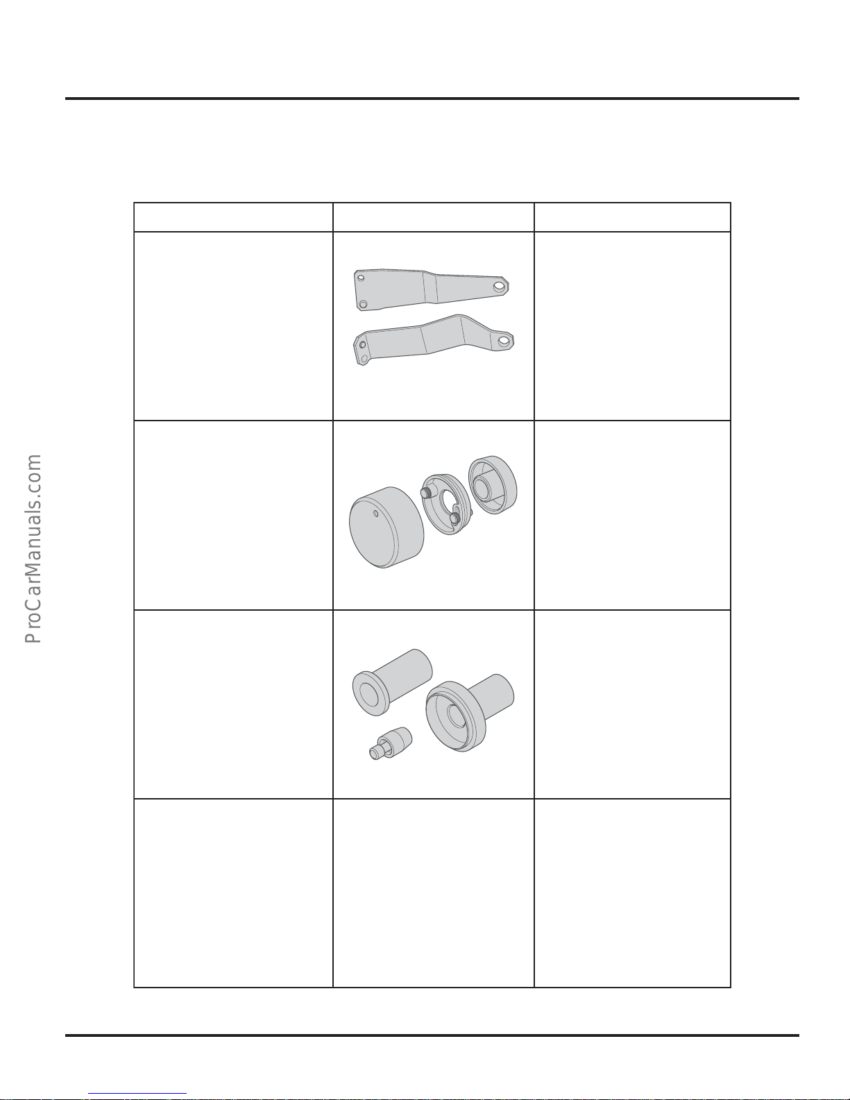
Designation Tool Usage
Service
Service
T10126
Transport Shackle
T10207
Assembly Equipment
T10208
Assembly Equipment
To transport the
V10-TDI engine
with workshop
crane VAS 6100
303_108
To install the PTFE
crankshaft gasket on
the gearbox side
303_109
To install the PTFE
crankshaft gasket on
the alternator shaft
T10210
Caliper
303_110
Figure not available
at time of printing
To align the pumpinjector units
43
Page 48
Notes
_____________________________________________________________________________________
_____________________________________________________________________________________
_____________________________________________________________________________________
_____________________________________________________________________________________
_____________________________________________________________________________________
_____________________________________________________________________________________
_____________________________________________________________________________________
_____________________________________________________________________________________
_____________________________________________________________________________________
_____________________________________________________________________________________
_____________________________________________________________________________________
_____________________________________________________________________________________
_____________________________________________________________________________________
_____________________________________________________________________________________
_____________________________________________________________________________________
_____________________________________________________________________________________
_____________________________________________________________________________________
_____________________________________________________________________________________
_____________________________________________________________________________________
_____________________________________________________________________________________
_____________________________________________________________________________________
_____________________________________________________________________________________
44
Page 49
Knowledge Assessment
An on-line Knowledge Assessment (exam) is available for this Self-Study Program.
The Knowledge Assessment may or may not be required for Certification.
You can find this Knowledge Assessment at:
www.vwwebsource.com
From the vwwebsource.com Homepage, do the following:
– Click on the Certification tab
– Type the course number in the Search box
For Assistance, please call:
Or, E-Mail:
– Click “Go!” and wait until the screen refreshes
– Click “Start” to begin the Assessment
Certification Program Headquarters
1 - 877 - CU4 - CERT
(1 - 877 - 284 - 2378)
(8:00 a.m. to 8:00 p.m. EST)
Comments@ VWCertification.com
45
Page 50

The Touareg
V10-TDI Engine
Volkswagen of America, Inc.
3800 Hamlin Road
Auburn Hills, MI 48326
Printed in U.S.A.
March 2003
 Loading...