

Page 1

P
r
o
t
e
c
t
e
d
b
y
c
o
p
y
r
i
g
h
t
.
C
o
p
y
i
n
g
f
o
r
p
r
i
v
a
t
e
o
r
c
o
m
m
e
r
c
i
a
l
p
u
r
p
o
s
e
s
,
i
n
p
a
r
t
o
r
i
n
w
h
o
l
e
,
i
s
n
o
t
p
e
r
m
i
t
t
e
d
u
n
l
e
s
s
a
u
t
h
o
r
i
s
e
d
b
y
V
o
l
k
s
w
a
g
e
n
A
G
.
V
o
l
k
s
w
a
g
e
n
A
G
d
o
e
s
n
o
t
g
u
a
r
a
n
t
e
e
o
r
a
c
c
e
p
t
a
n
y
l
i
a
b
i
l
i
t
y
w
i
t
h
r
e
s
p
e
c
t
t
o
t
h
e
c
o
r
r
e
c
t
n
e
s
s
o
f
i
n
f
o
r
m
a
t
i
o
n
i
n
t
h
i
s
d
o
c
u
m
e
n
t
.
C
o
p
y
r
i
g
h
t
b
y
V
o
l
k
s
w
a
g
e
n
A
G
.
Service Training
Self-study Programme 527
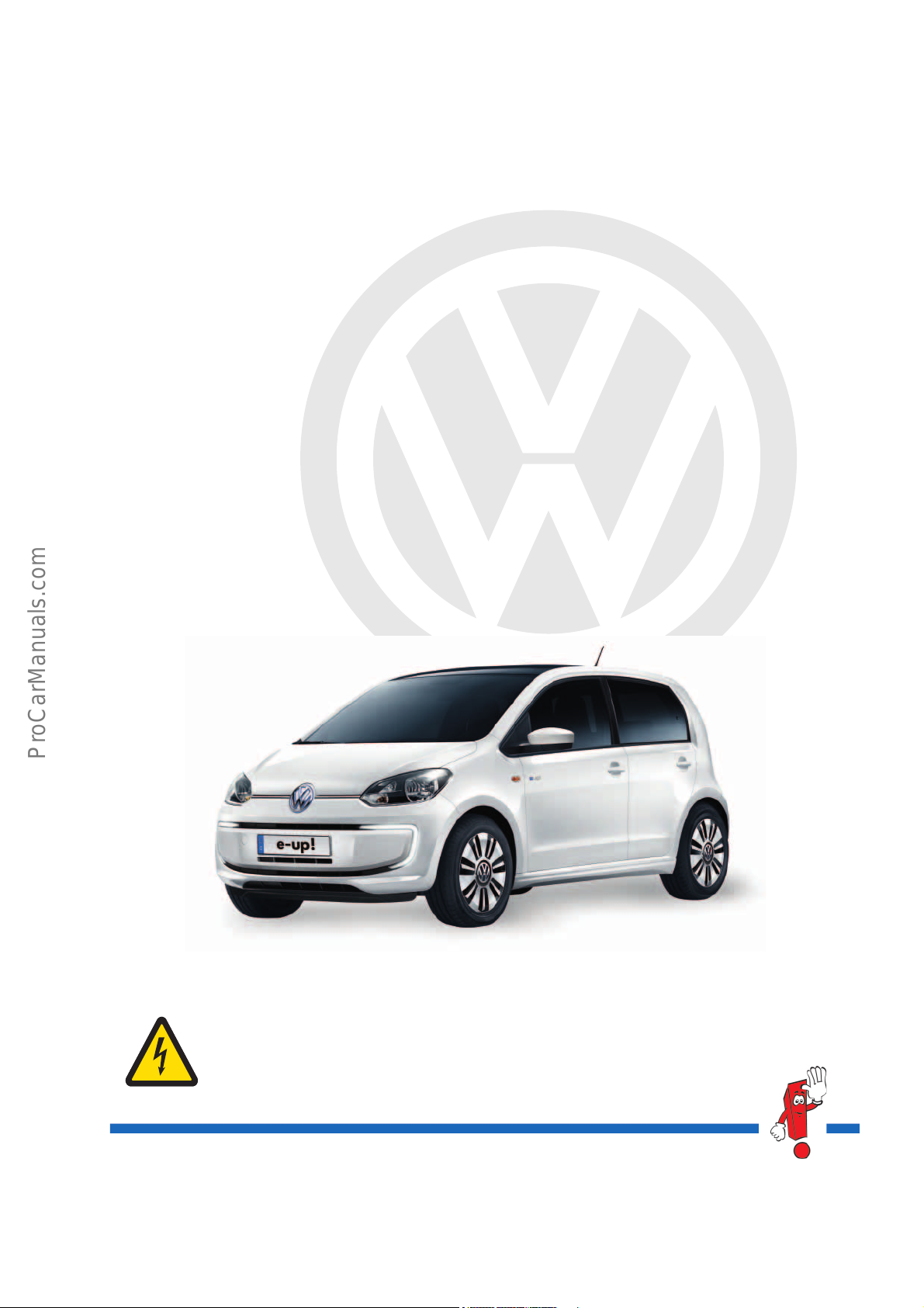
The e-up!
Page 2
P
r
o
t
e
c
t
e
d
b
y
c
o
p
y
r
i
g
h
t
.
C
o
p
y
i
n
g
f
o
r
p
r
i
v
a
t
e
o
r
c
o
m
m
e
r
c
i
a
l
p
u
r
p
o
s
e
s
,
i
n
p
a
r
t
o
r
i
n
w
h
o
l
e
,
i
s
n
o
t
p
e
r
m
i
t
t
e
d
u
n
l
e
s
s
a
u
t
h
o
r
i
s
e
d
b
y
V
o
l
k
s
w
a
g
e
n
A
G
.
V
o
l
k
s
w
a
g
e
n
A
G
d
o
e
s
n
o
t
g
u
a
r
a
n
t
e
e
o
r
a
c
c
e
p
t
a
n
y
l
i
a
b
i
l
i
t
y
w
i
t
h
r
e
s
p
e
c
t
t
o
t
h
e
c
o
r
r
e
c
t
n
e
s
s
o
f
i
n
f
o
r
m
a
t
i
o
n
i
n
t
h
i
s
d
o
c
u
m
e
n
t
.
C
o
p
y
r
i
g
h
t
b
y
V
o
l
k
s
w
a
g
e
n
A
G
.
s527_001
The e-up! is the first electric vehicle from Volkswagen to go into mass production.
Its distinctive characteristic is the curved light signature; an LED daytime running light in the front bumper.
As well using innovative, sophisticated technology, the primary objective for the e-up! was to develop a safe
vehicle which meets demand and is suitable for everyday use.
It is the first time that large-scale use of renewable energy has been possible. Exclusively in Germany, Volkswagen
is offering electricity under the name BluePower*. The energy is generated without CO
hydroelectric power plants*.
The pleasure of driving and environmental awareness are no longer mutually exclusive.
The maximum drive torque of the electric drive is 210 newton metres and the maximum power is 60 kilowatts.
This means the e-up! can powerfully accelerate from zero km/h.
Aerodynamic features and the lithium ion high-voltage battery with a capacity of 18.7 kWh enable a range of up
to 160 km.
* Varies according to country.
and is taken solely from
2
Caution! Hazardous electric voltage!
The Self-study Programme describes
the design and function of
new developments.
The contents will not be updated.
For current testing, adjustment and repair
instructions, refer to the relevant service
literature.
Important
Note
2
Page 3
P
r
o
t
e
c
t
e
d
b
y
c
o
p
y
r
i
g
h
t
.
C
o
p
y
i
n
g
f
o
r
p
r
i
v
a
t
e
o
r
c
o
m
m
e
r
c
i
a
l
p
u
r
p
o
s
e
s
,
i
n
p
a
r
t
o
r
i
n
w
h
o
l
e
,
i
s
n
o
t
p
e
r
m
i
t
t
e
d
u
n
l
e
s
s
a
u
t
h
o
r
i
s
e
d
b
y
V
o
l
k
s
w
a
g
e
n
A
G
.
V
o
l
k
s
w
a
g
e
n
A
G
d
o
e
s
n
o
t
g
u
a
r
a
n
t
e
e
o
r
a
c
c
e
p
t
a
n
y
l
i
a
b
i
l
i
t
y
w
i
t
h
r
e
s
p
e
c
t
t
o
t
h
e
c
o
r
r
e
c
t
n
e
s
s
o
f
i
n
f
o
r
m
a
t
i
o
n
i
n
t
h
i
s
d
o
c
u
m
e
n
t
.
C
o
p
y
r
i
g
h
t
b
y
V
o
l
k
s
w
a
g
e
n
A
G
.
Contents
Introduction . . . . . . . . . . . . . . . . . . . . . . . . . . . . . . . . . . . . . . . . . . . . . . . . . . . . . . 4
Body . . . . . . . . . . . . . . . . . . . . . . . . . . . . . . . . . . . . . . . . . . . . . . . . . . . . . . . . . . . . 8
Power transmission. . . . . . . . . . . . . . . . . . . . . . . . . . . . . . . . . . . . . . . . . . . . . . . 13
Running gear . . . . . . . . . . . . . . . . . . . . . . . . . . . . . . . . . . . . . . . . . . . . . . . . . . . .14
Heating and air conditioning . . . . . . . . . . . . . . . . . . . . . . . . . . . . . . . . . . . . . . .16
High-voltage system . . . . . . . . . . . . . . . . . . . . . . . . . . . . . . . . . . . . . . . . . . . . .25
Electrical system . . . . . . . . . . . . . . . . . . . . . . . . . . . . . . . . . . . . . . . . . . . . . . . . .42
Infotainment . . . . . . . . . . . . . . . . . . . . . . . . . . . . . . . . . . . . . . . . . . . . . . . . . . . . 49
Car-Net . . . . . . . . . . . . . . . . . . . . . . . . . . . . . . . . . . . . . . . . . . . . . . . . . . . . . . . .54
Service . . . . . . . . . . . . . . . . . . . . . . . . . . . . . . . . . . . . . . . . . . . . . . . . . . . . . . . . .63
3
Page 4
P
r
o
t
e
c
t
e
d
b
y
c
o
p
y
r
i
g
h
t
.
C
o
p
y
i
n
g
f
o
r
p
r
i
v
a
t
e
o
r
c
o
m
m
e
r
c
i
a
l
p
u
r
p
o
s
e
s
,
i
n
p
a
r
t
o
r
i
n
w
h
o
l
e
,
i
s
n
o
t
p
e
r
m
i
t
t
e
d
u
n
l
e
s
s
a
u
t
h
o
r
i
s
e
d
b
y
V
o
l
k
s
w
a
g
e
n
A
G
.
V
o
l
k
s
w
a
g
e
n
A
G
d
o
e
s
n
o
t
g
u
a
r
a
n
t
e
e
o
r
a
c
c
e
p
t
a
n
y
l
i
a
b
i
l
i
t
y
w
i
t
h
r
e
s
p
e
c
t
t
o
t
h
e
c
o
r
r
e
c
t
n
e
s
s
o
f
i
n
f
o
r
m
a
t
i
o
n
i
n
t
h
i
s
d
o
c
u
m
e
n
t
.
C
o
p
y
r
i
g
h
t
b
y
V
o
l
k
s
w
a
g
e
n
A
G
.
Introduction
s527_003
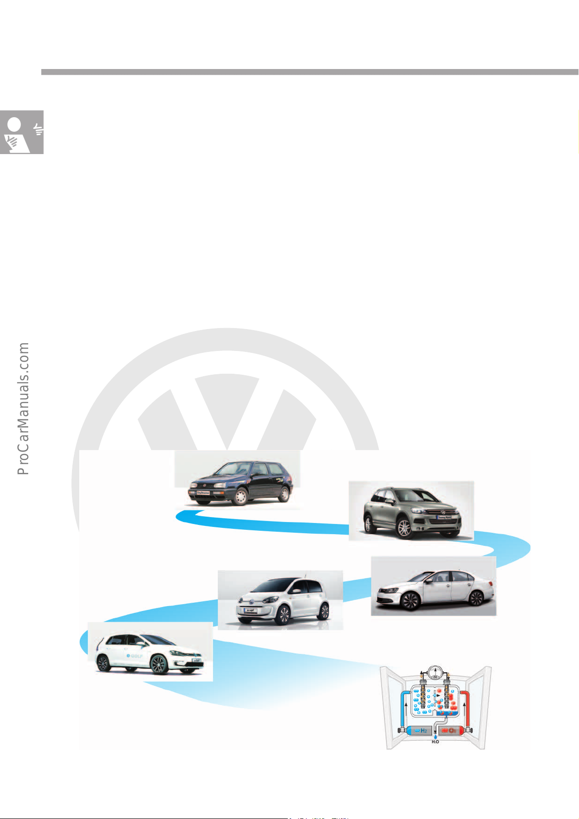
Fuel cell
e-Golf
2014
e-up! 2013
Jetta Hybrid 2012
Touareg Hybrid 2010
Golf CitySTROMer 1993
E-mobility – the path to the future
Since the 1970s, Volkswagen has been intensely involved in the field of electric mobility. Many concept studies
have been developed since then and in the 90s, a small number of Golf CitySTROMer vehicles even went into
production.
In 2010, the Touareg Hybrid was the first vehicle with an electric hybrid drive from Volkswagen to go into mass
production. The second vehicle series was the Jetta Hybrid, produced in 2012, which combined a combustion
engine and a three-phase current drive.
The e-up! is the first fully electric vehicle to be introduced and will be followed by the e-Golf in 2014. The new
lithium ion high-voltage battery in the e-up! is an important building block for e-mobility which simultaneously
provides technology suitable for everyday use.
Looking to the future, Volkswagen are already researching and developing further concepts such as the use of fuel
cells.
Under the terms “Think Blue” and “BlueMotion”, Volkswagen combines advanced environmentally-friendly
technology, from BlueMotion technologies to hybrid drives and electric drives.
The objective is CO
neutral, sustainable and safe electric mobility that is suitable for everyday use.
2
4
Page 5
P
r
o
t
e
c
t
e
d
b
y
c
o
p
y
r
i
g
h
t
.
C
o
p
y
i
n
g
f
o
r
p
r
i
v
a
t
e
o
r
c
o
m
m
e
r
c
i
a
l
p
u
r
p
o
s
e
s
,
i
n
p
a
r
t
o
r
i
n
w
h
o
l
e
,
i
s
n
o
t
p
e
r
m
i
t
t
e
d
u
n
l
e
s
s
a
u
t
h
o
r
i
s
e
d
b
y
V
o
l
k
s
w
a
g
e
n
A
G
.
V
o
l
k
s
w
a
g
e
n
A
G
d
o
e
s
n
o
t
g
u
a
r
a
n
t
e
e
o
r
a
c
c
e
p
t
a
n
y
l
i
a
b
i
l
i
t
y
w
i
t
h
r
e
s
p
e
c
t
t
o
t
h
e
c
o
r
r
e
c
t
n
e
s
s
o
f
i
n
f
o
r
m
a
t
i
o
n
i
n
t
h
i
s
d
o
c
u
m
e
n
t
.
C
o
p
y
r
i
g
h
t
b
y
V
o
l
k
s
w
a
g
e
n
A
G
.
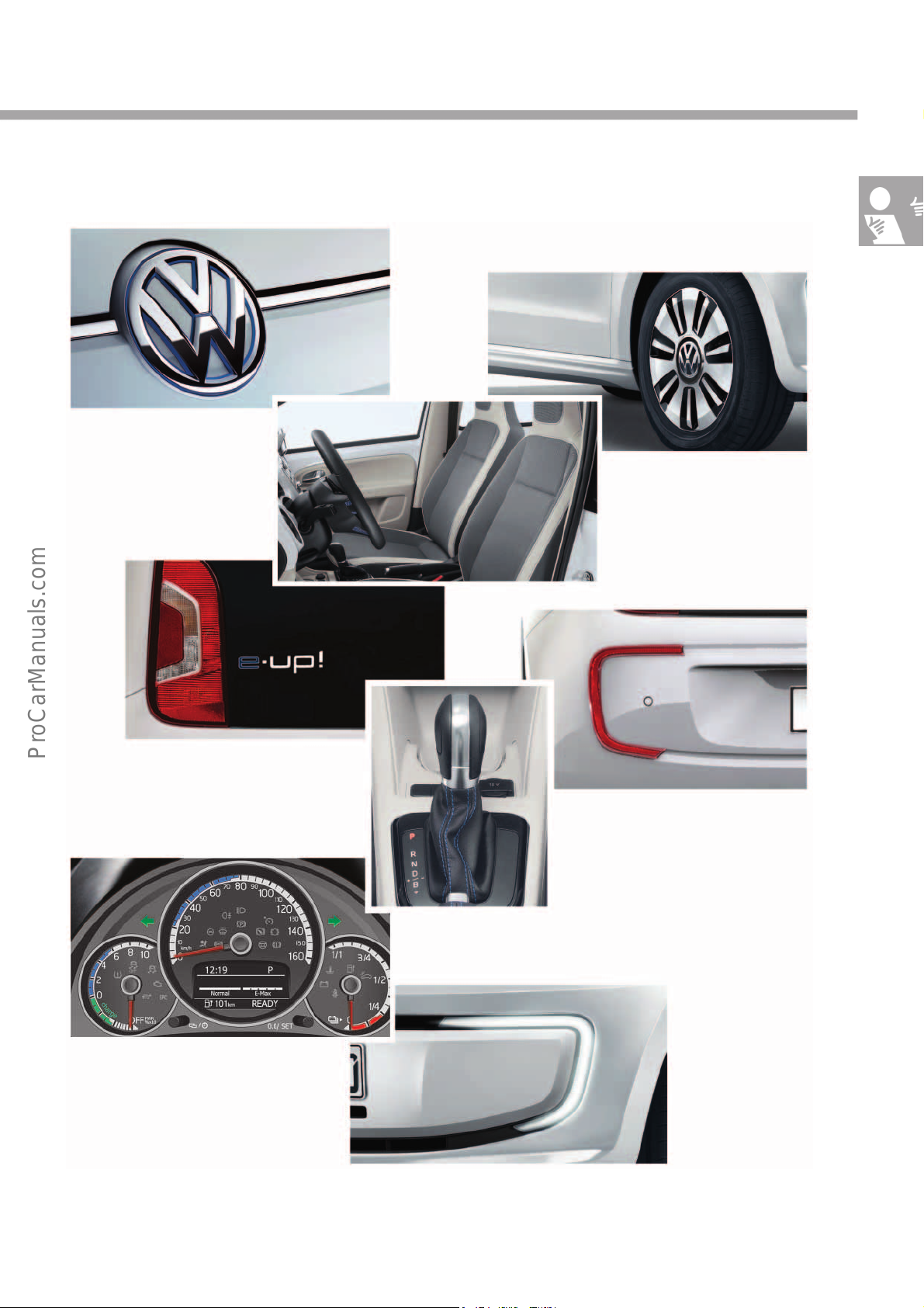
Distinguishing features of the e-up!
s527_005
15-inch alloy wheels
Specially designed seat covers
Reflectors in a curved electric vehicle
signature
Selector lever with blue seam and gear
display “B”
e-up! badge on the rear lid
Dash panel insert with electric vehicle-specific
display
LED daytime running
lights at front
Volkswagen badge
with blue ring
5
Page 6
P
r
o
t
e
c
t
e
d
b
y
c
o
p
y
r
i
g
h
t
.
C
o
p
y
i
n
g
f
o
r
p
r
i
v
a
t
e
o
r
c
o
m
m
e
r
c
i
a
l
p
u
r
p
o
s
e
s
,
i
n
p
a
r
t
o
r
i
n
w
h
o
l
e
,
i
s
n
o
t
p
e
r
m
i
t
t
e
d
u
n
l
e
s
s
a
u
t
h
o
r
i
s
e
d
b
y
V
o
l
k
s
w
a
g
e
n
A
G
.
V
o
l
k
s
w
a
g
e
n
A
G
d
o
e
s
n
o
t
g
u
a
r
a
n
t
e
e
o
r
a
c
c
e
p
t
a
n
y
l
i
a
b
i
l
i
t
y
w
i
t
h
r
e
s
p
e
c
t
t
o
t
h
e
c
o
r
r
e
c
t
n
e
s
s
o
f
i
n
f
o
r
m
a
t
i
o
n
i
n
t
h
i
s
d
o
c
u
m
e
n
t
.
C
o
p
y
r
i
g
h
t
b
y
V
o
l
k
s
w
a
g
e
n
A
G
.
s527_007
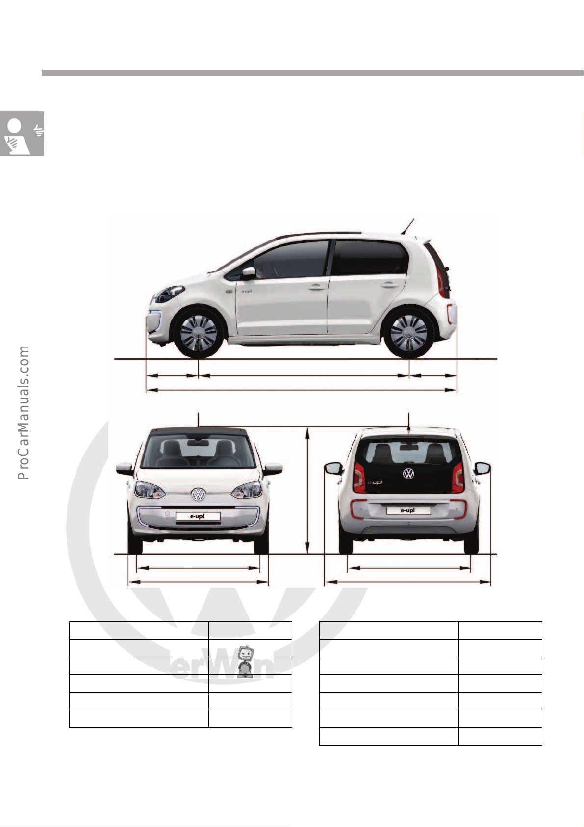
1428mm
1645mm
2421mm
3540mm
1481mm
584mm 535mm
1424mm
1910mm
Introduction
Technical data
Exterior dimensions and weights
The data refers to a vehicle without driver, with standard equipment and electric drive,
a lithium ion high-voltage battery and tyre size 165/65 R15. The dimensions correspond to those of the up!,
introduced to the market in 2011, with some minor deviations.
Exterior dimensions
Length 3540mm
Width 1645mm
Height 1481mm
Wheelbase 2421mm
Track width at front 1428mm
Weights/further data
Gross vehicle weight rating 1500kg
DIN kerb weight* 1139kg
Weight of the high-voltage battery 230kg
Turning circle 9.8m
Nominal energy 18.7kWh
Track width at rear 1424mm
Max. power/max. torque 60kW/210Nm
Drag coefficient 0.308 c
d
* DIN ≙ Deutsche Industrie Norm
(German Industry Standard)
6
Page 7
P
r
o
t
e
c
t
e
d
b
y
c
o
p
y
r
i
g
h
t
.
C
o
p
y
i
n
g
f
o
r
p
r
i
v
a
t
e
o
r
c
o
m
m
e
r
c
i
a
l
p
u
r
p
o
s
e
s
,
i
n
p
a
r
t
o
r
i
n
w
h
o
l
e
,
i
s
n
o
t
p
e
r
m
i
t
t
e
d
u
n
l
e
s
s
a
u
t
h
o
r
i
s
e
d
b
y
V
o
l
k
s
w
a
g
e
n
A
G
.
V
o
l
k
s
w
a
g
e
n
A
G
d
o
e
s
n
o
t
g
u
a
r
a
n
t
e
e
o
r
a
c
c
e
p
t
a
n
y
l
i
a
b
i
l
i
t
y
w
i
t
h
r
e
s
p
e
c
t
t
o
t
h
e
c
o
r
r
e
c
t
n
e
s
s
o
f
i
n
f
o
r
m
a
t
i
o
n
i
n
t
h
i
s
d
o
c
u
m
e
n
t
.
C
o
p
y
r
i
g
h
t
b
y
V
o
l
k
s
w
a
g
e
n
A
G
.
s527_009
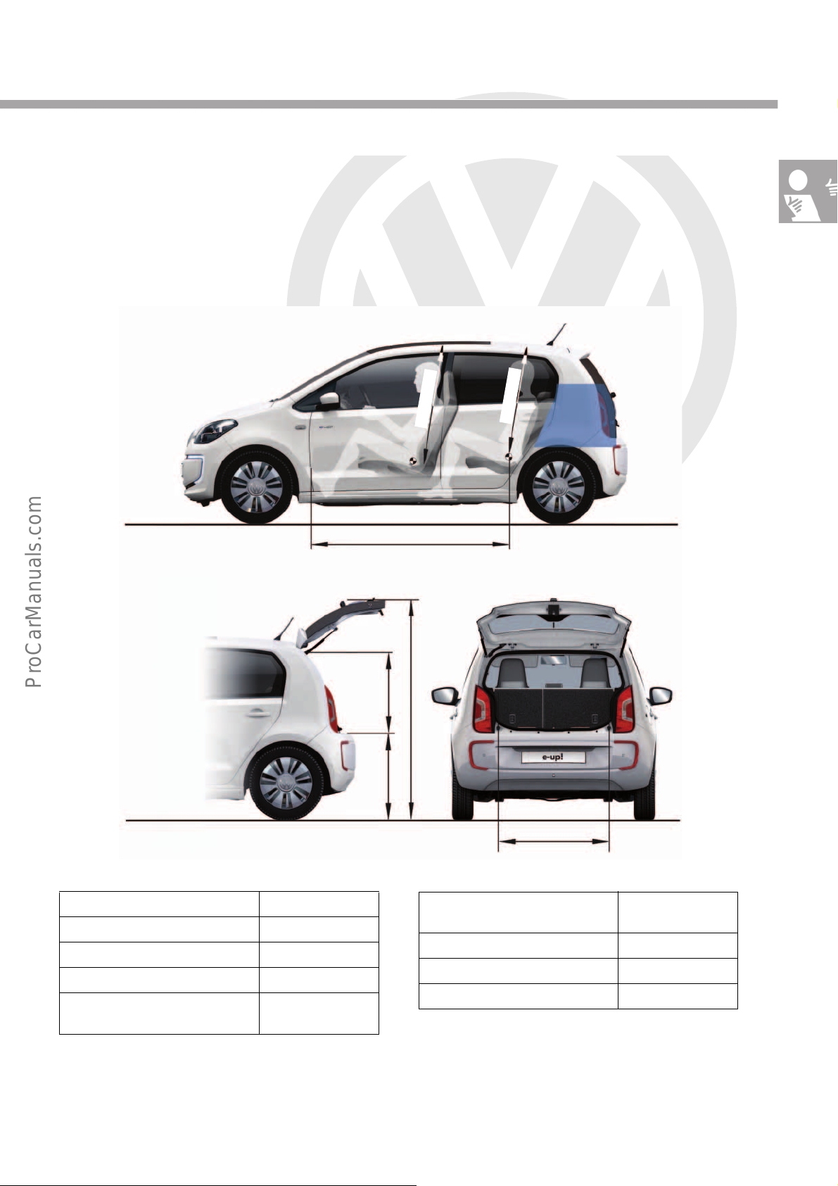
868mm
773 mm
570 mm
1
0
2
2
m
m
9
4
7m
m
1613mm
1994 mm
Interior dimensions and volumes
Interior dimensions and volumes
Length of vehicle interior 1613mm
Luggage compartment volume 250litres
Height of open rear lid 1994mm
Height of load sill 773mm
Height of luggage compartment
aperture
570mm
Width of luggage compartment
868mm
aperture
Front headroom, max. 1022mm
Headroom – 2nd seat row 947mm
Legroom, 2nd seat row *
* Sufficient legroom can only be obtained
by reducing the legroom of the front seats.
7
Page 8
P
r
o
t
e
c
t
e
d
b
y
c
o
p
y
r
i
g
h
t
.
C
o
p
y
i
n
g
f
o
r
p
r
i
v
a
t
e
o
r
c
o
m
m
e
r
c
i
a
l
p
u
r
p
o
s
e
s
,
i
n
p
a
r
t
o
r
i
n
w
h
o
l
e
,
i
s
n
o
t
p
e
r
m
i
t
t
e
d
u
n
l
e
s
s
a
u
t
h
o
r
i
s
e
d
b
y
V
o
l
k
s
w
a
g
e
n
A
G
.
V
o
l
k
s
w
a
g
e
n
A
G
d
o
e
s
n
o
t
g
u
a
r
a
n
t
e
e
o
r
a
c
c
e
p
t
a
n
y
l
i
a
b
i
l
i
t
y
w
i
t
h
r
e
s
p
e
c
t
t
o
t
h
e
c
o
r
r
e
c
t
n
e
s
s
o
f
i
n
f
o
r
m
a
t
i
o
n
i
n
t
h
i
s
d
o
c
u
m
e
n
t
.
C
o
p
y
r
i
g
h
t
b
y
V
o
l
k
s
w
a
g
e
n
A
G
.
Body
s527_011
B-pillar e-up!
B-pillar up!
s527_002
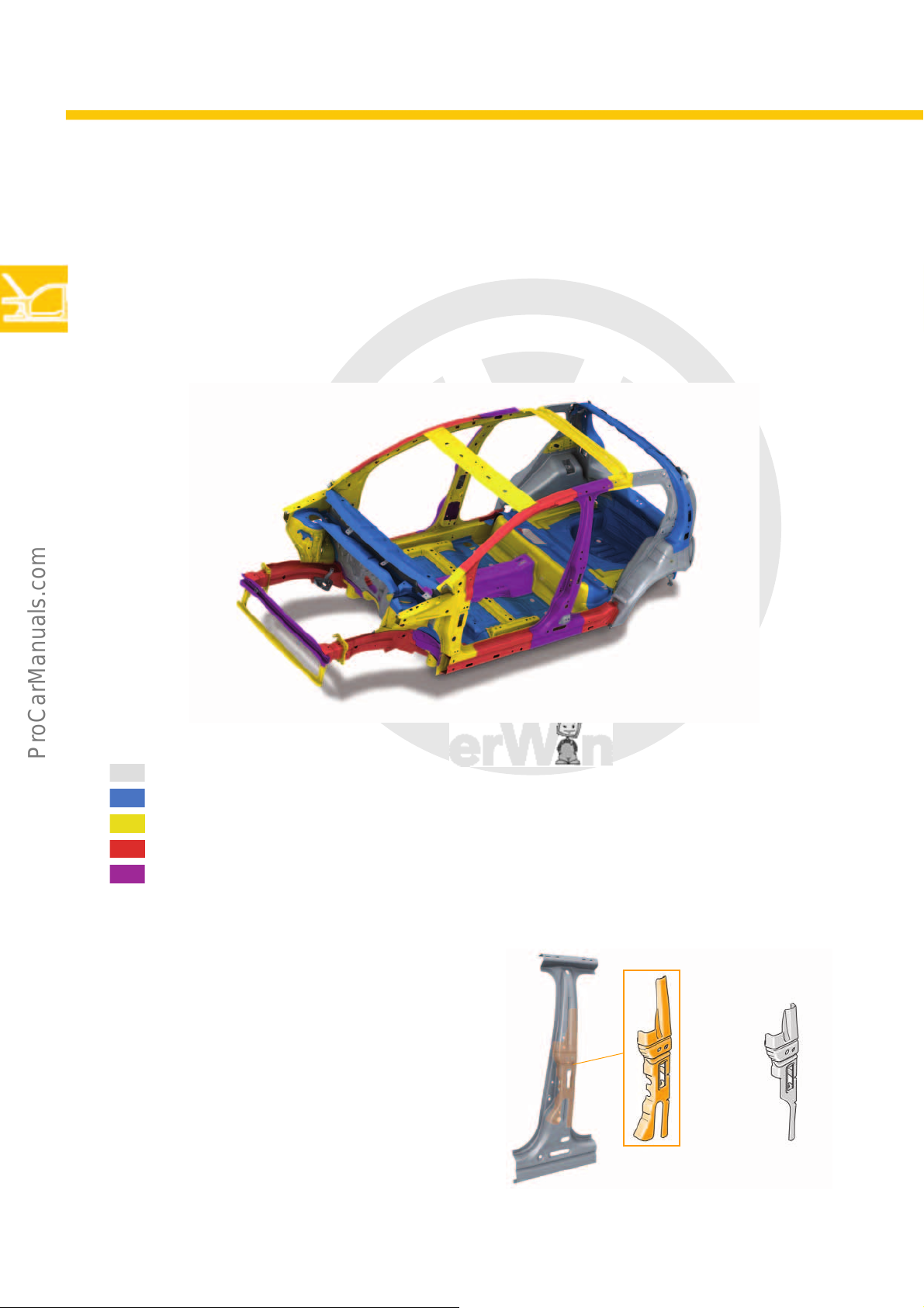
Body structure
The development from up! to e-up! has also influenced the body structure. The vehicle floor has been modified and
reinforced in order to create space for the high-voltage battery. Stringent safety requirements for high voltages
have meant an increase in the number of hot formed parts and changes to the geometry and quality of the
materials. The front part of the longitudinal member of the e-up! is structurally identical to that of the up!. The e-up!
is only available as a 4-door model.
Strengths of steel sheets
Soft steel sheet metal <350 MPa
Strengthened steel sheet metal <590MPa
Modern strengthened steel sheet metal <980MPa
Ultra-strengthened steel sheet metal <1150MPa
Ultra-strengthened (hot formed) steel sheet metal >1400 MPa
Additional B-pillar reinforcement
The B-pillar has been reinforced in the mid-section to
meet special crash requirements. This is the only
component in the upper body structure which has a
different geometry and material from the up!
8
Page 9
P
r
o
t
e
c
t
e
d
b
y
c
o
p
y
r
i
g
h
t
.
C
o
p
y
i
n
g
f
o
r
p
r
i
v
a
t
e
o
r
c
o
m
m
e
r
c
i
a
l
p
u
r
p
o
s
e
s
,
i
n
p
a
r
t
o
r
i
n
w
h
o
l
e
,
i
s
n
o
t
p
e
r
m
i
t
t
e
d
u
n
l
e
s
s
a
u
t
h
o
r
i
s
e
d
b
y
V
o
l
k
s
w
a
g
e
n
A
G
.
V
o
l
k
s
w
a
g
e
n
A
G
d
o
e
s
n
o
t
g
u
a
r
a
n
t
e
e
o
r
a
c
c
e
p
t
a
n
y
l
i
a
b
i
l
i
t
y
w
i
t
h
r
e
s
p
e
c
t
t
o
t
h
e
c
o
r
r
e
c
t
n
e
s
s
o
f
i
n
f
o
r
m
a
t
i
o
n
i
n
t
h
i
s
d
o
c
u
m
e
n
t
.
C
o
p
y
r
i
g
h
t
b
y
V
o
l
k
s
w
a
g
e
n
A
G
.
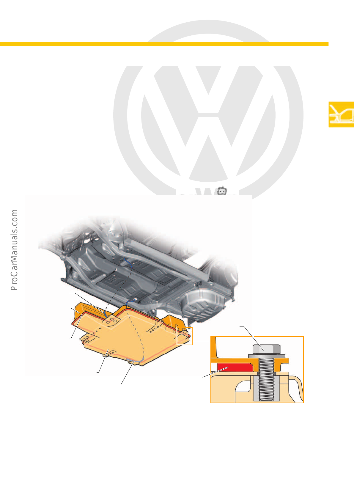
Lower shell
Upper shell
Threaded
connection
Glued joint
s527_115
s527_112
Glued joint
Earth connection
Earth connection
High-voltage battery housing
The high-voltage battery is secured in a housing under the vehicle. The housing consists of two main parts: the
upper and lower shells. The upper shell is made of plastic and coated in aluminium to ensure electromagnetic
compatibility. The pressure equalisation elements are part of the upper shell. The lower shell is made of metal.
The fixing rails for the battery cell pairs and the crash cross members are part of the lower shell. The upper and
lower shells are bolted together and glued. A check is then carried out to ensure no water can enter or gas can
escape. Potential equalisation between the housing and vehicle is via two earth connections to the vehicle.
9
Page 10
P
r
o
t
e
c
t
e
d
b
y
c
o
p
y
r
i
g
h
t
.
C
o
p
y
i
n
g
f
o
r
p
r
i
v
a
t
e
o
r
c
o
m
m
e
r
c
i
a
l
p
u
r
p
o
s
e
s
,
i
n
p
a
r
t
o
r
i
n
w
h
o
l
e
,
i
s
n
o
t
p
e
r
m
i
t
t
e
d
u
n
l
e
s
s
a
u
t
h
o
r
i
s
e
d
b
y
V
o
l
k
s
w
a
g
e
n
A
G
.
V
o
l
k
s
w
a
g
e
n
A
G
d
o
e
s
n
o
t
g
u
a
r
a
n
t
e
e
o
r
a
c
c
e
p
t
a
n
y
l
i
a
b
i
l
i
t
y
w
i
t
h
r
e
s
p
e
c
t
t
o
t
h
e
c
o
r
r
e
c
t
n
e
s
s
o
f
i
n
f
o
r
m
a
t
i
o
n
i
n
t
h
i
s
d
o
c
u
m
e
n
t
.
C
o
p
y
r
i
g
h
t
b
y
V
o
l
k
s
w
a
g
e
n
A
G
.
Body
s527_015 s527_113
Underbody cover
s527_017
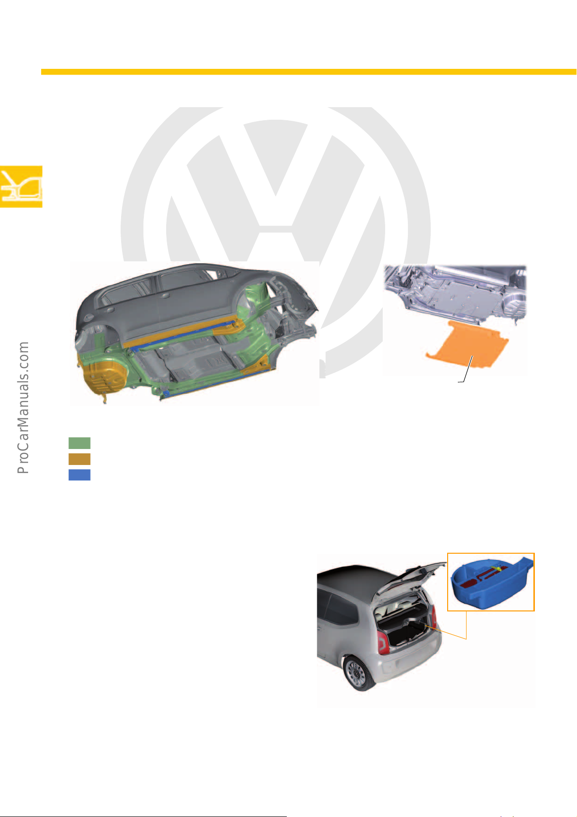
Underbody
The middle underbody and the back vehicle floor had to be redeveloped for the e-up! due to the built-in highvoltage battery. The underbody must meet crash requirements The e-up! is equipped with an underbody cover to
protect it from damage and corrosion. The underbody cover is mounted on the lower shell of the high-voltage
battery and the longitudinal members.
Underbody coating layer thickness
300μm
500μm
1200μm
Cargo management in the luggage compartment
The floor in the luggage compartment of the e-up! has
also been redesigned and has the following
functions:
• Accommodation of the vehicle tool kit
• Accommodation of the charging cable
• Reinforcement measures and maintenance of
clearances to protect the high-voltage battery in
rear crashes
10
Page 11
P
r
o
t
e
c
t
e
d
b
y
c
o
p
y
r
i
g
h
t
.
C
o
p
y
i
n
g
f
o
r
p
r
i
v
a
t
e
o
r
c
o
m
m
e
r
c
i
a
l
p
u
r
p
o
s
e
s
,
i
n
p
a
r
t
o
r
i
n
w
h
o
l
e
,
i
s
n
o
t
p
e
r
m
i
t
t
e
d
u
n
l
e
s
s
a
u
t
h
o
r
i
s
e
d
b
y
V
o
l
k
s
w
a
g
e
n
A
G
.
V
o
l
k
s
w
a
g
e
n
A
G
d
o
e
s
n
o
t
g
u
a
r
a
n
t
e
e
o
r
a
c
c
e
p
t
a
n
y
l
i
a
b
i
l
i
t
y
w
i
t
h
r
e
s
p
e
c
t
t
o
t
h
e
c
o
r
r
e
c
t
n
e
s
s
o
f
i
n
f
o
r
m
a
t
i
o
n
i
n
t
h
i
s
d
o
c
u
m
e
n
t
.
C
o
p
y
r
i
g
h
t
b
y
V
o
l
k
s
w
a
g
e
n
A
G
.
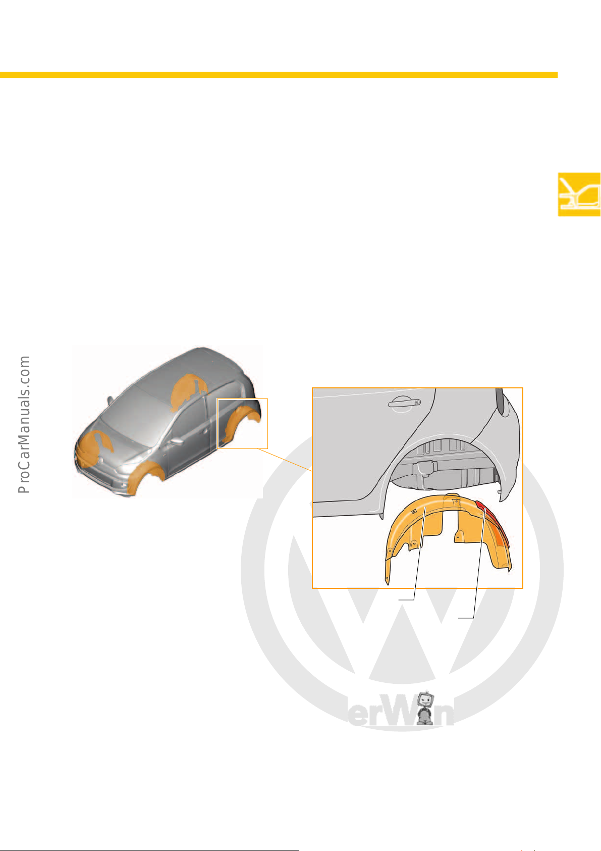
Acoustic measures
Rear wheel housing liner
s527_019
s527_116
Glued acoustic absorber
To increase passenger comfort and reduce noise transmission from the drive and its vicinity, additional measures
have been taken concerning the vehicle acoustics. These measures have mostly been implemented using acoustic
fleeces and can be divided into two areas:
1. Rear noises
2. Front end
Unlike the standard up!, the e-up! also has rear wheel housing liners. The front and rear wheel housing liners are
fitted with acoustic absorbers (damping sections) on the inside.
11
Page 12
P
r
o
t
e
c
t
e
d
b
y
c
o
p
y
r
i
g
h
t
.
C
o
p
y
i
n
g
f
o
r
p
r
i
v
a
t
e
o
r
c
o
m
m
e
r
c
i
a
l
p
u
r
p
o
s
e
s
,
i
n
p
a
r
t
o
r
i
n
w
h
o
l
e
,
i
s
n
o
t
p
e
r
m
i
t
t
e
d
u
n
l
e
s
s
a
u
t
h
o
r
i
s
e
d
b
y
V
o
l
k
s
w
a
g
e
n
A
G
.
V
o
l
k
s
w
a
g
e
n
A
G
d
o
e
s
n
o
t
g
u
a
r
a
n
t
e
e
o
r
a
c
c
e
p
t
a
n
y
l
i
a
b
i
l
i
t
y
w
i
t
h
r
e
s
p
e
c
t
t
o
t
h
e
c
o
r
r
e
c
t
n
e
s
s
o
f
i
n
f
o
r
m
a
t
i
o
n
i
n
t
h
i
s
d
o
c
u
m
e
n
t
.
C
o
p
y
r
i
g
h
t
b
y
V
o
l
k
s
w
a
g
e
n
A
G
.
Body
s527_004
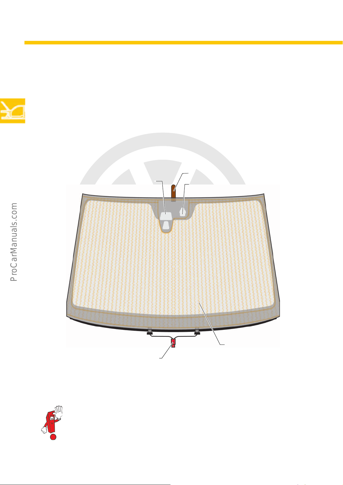
Heating wires
Heating field connection
Earth strap for the body
Window for the laser sensor of the City Emergency
Brake
Window for the humidity sender for air conditioning
system G260
Windscreen heater
The e-up is equipped with a surface windscreen heater as standard. The trapezoidal arrangement of the heating
wires ensures that the entire surface can be kept free of condensation or de-iced. Depending on the model, the
windscreen is available with or without a sensor for the City Emergency Brake. This also dictates the design of the
interior mirror. The windscreen does not have a seal around the edge; instead it is glued into the frame. If the e-up!
has a sliding sunroof, the upper part of the frame is designed as a lip profile.
12
The earth strap is bolted under the interior light at the earth point of the body.
Page 13
P
r
o
t
e
c
t
e
d
b
y
c
o
p
y
r
i
g
h
t
.
C
o
p
y
i
n
g
f
o
r
p
r
i
v
a
t
e
o
r
c
o
m
m
e
r
c
i
a
l
p
u
r
p
o
s
e
s
,
i
n
p
a
r
t
o
r
i
n
w
h
o
l
e
,
i
s
n
o
t
p
e
r
m
i
t
t
e
d
u
n
l
e
s
s
a
u
t
h
o
r
i
s
e
d
b
y
V
o
l
k
s
w
a
g
e
n
A
G
.
V
o
l
k
s
w
a
g
e
n
A
G
d
o
e
s
n
o
t
g
u
a
r
a
n
t
e
e
o
r
a
c
c
e
p
t
a
n
y
l
i
a
b
i
l
i
t
y
w
i
t
h
r
e
s
p
e
c
t
t
o
t
h
e
c
o
r
r
e
c
t
n
e
s
s
o
f
i
n
f
o
r
m
a
t
i
o
n
i
n
t
h
i
s
d
o
c
u
m
e
n
t
.
C
o
p
y
r
i
g
h
t
b
y
V
o
l
k
s
w
a
g
e
n
A
G
.
Power transmission
s527_021
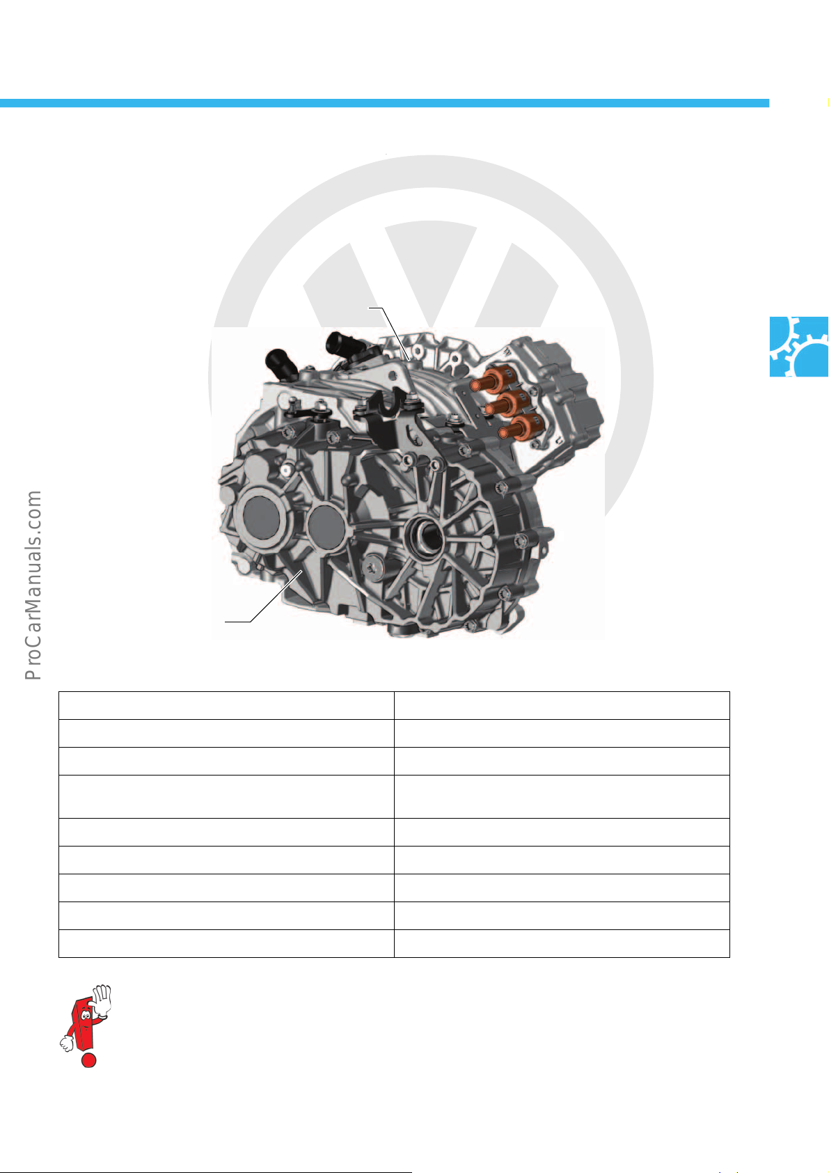
1-gear gearbox 0CZ
Three-phase current drive VX54
1-gear gearbox 0CZ
The e-up! is equipped with the 1-gear gearbox 0CZ. The gearbox and the three-phase current drive VX54 form a
single unit. The challenge was to construct a gearbox that remains quiet over the entire motor speed range.
Technical data
Gearbox designation 0CZ
Number of gears 1
Transmission levels 2
Transmission ratios Level 1: 1.577 (Z1 = 26; Z2 = 41)
Level 2: 5.176 (Z3 = 17; Z4 = 88)
Max. input torque 210Nm
Max. input motor speed 12,000rpm
Weight (with oil) 16.3kg
Oil volume 0.7l (for part number see ETKA)
Drive shafts Plugged connections
Further information can be found in Self-study Programme no. 529 “The e-up! Running Gear and
Power Transmission”.
13
Page 14
P
r
o
t
e
c
t
e
d
b
y
c
o
p
y
r
i
g
h
t
.
C
o
p
y
i
n
g
f
o
r
p
r
i
v
a
t
e
o
r
c
o
m
m
e
r
c
i
a
l
p
u
r
p
o
s
e
s
,
i
n
p
a
r
t
o
r
i
n
w
h
o
l
e
,
i
s
n
o
t
p
e
r
m
i
t
t
e
d
u
n
l
e
s
s
a
u
t
h
o
r
i
s
e
d
b
y
V
o
l
k
s
w
a
g
e
n
A
G
.
V
o
l
k
s
w
a
g
e
n
A
G
d
o
e
s
n
o
t
g
u
a
r
a
n
t
e
e
o
r
a
c
c
e
p
t
a
n
y
l
i
a
b
i
l
i
t
y
w
i
t
h
r
e
s
p
e
c
t
t
o
t
h
e
c
o
r
r
e
c
t
n
e
s
s
o
f
i
n
f
o
r
m
a
t
i
o
n
i
n
t
h
i
s
d
o
c
u
m
e
n
t
.
C
o
p
y
r
i
g
h
t
b
y
V
o
l
k
s
w
a
g
e
n
A
G
.
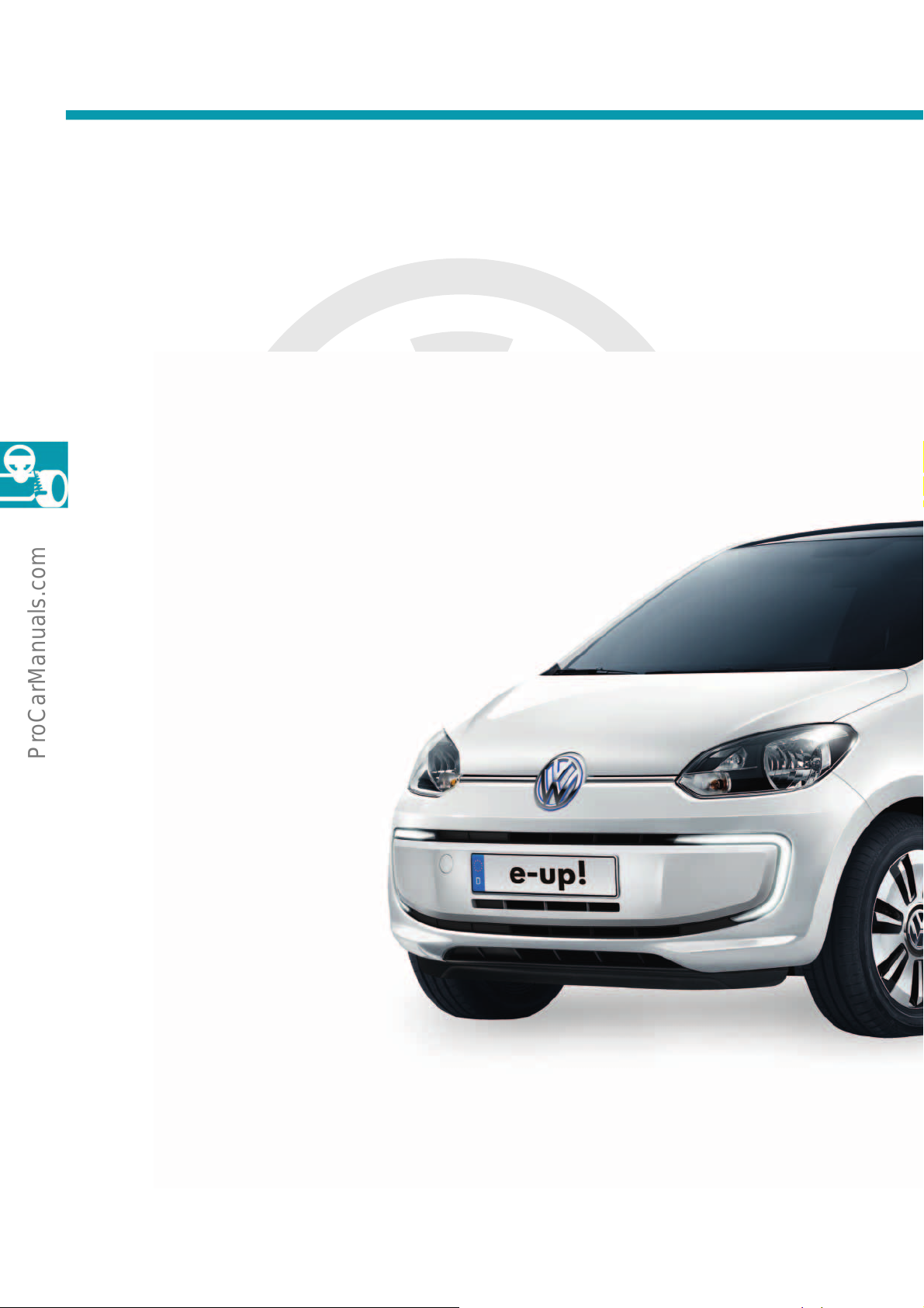
Running gear
An overview of the running gear
This overview explains the standard and optional running gear equipment for the e-up!.
The e-up! is fitted with a standard running gear. Its new features are the electromechanical brake servo (eBKV)
with a pressure accumulator made by Bosch, and the ESC/ABS made by TRW (EBC 460).
• Electromechanical brake servo (eBKV)
with brake system pressure accumulator
• Electromechanical power
steering C-EPS
(Column Electric Power
Steering) with integrated
steering angle sensor made
by TRW
• McPherson strut front suspension
14
• ESC/ABS, made by TRW
(Electronic Brake Control – EBC 460)
• Front disc brakes
Page 15
P
r
o
t
e
c
t
e
d
b
y
c
o
p
y
r
i
g
h
t
.
C
o
p
y
i
n
g
f
o
r
p
r
i
v
a
t
e
o
r
c
o
m
m
e
r
c
i
a
l
p
u
r
p
o
s
e
s
,
i
n
p
a
r
t
o
r
i
n
w
h
o
l
e
,
i
s
n
o
t
p
e
r
m
i
t
t
e
d
u
n
l
e
s
s
a
u
t
h
o
r
i
s
e
d
b
y
V
o
l
k
s
w
a
g
e
n
A
G
.
V
o
l
k
s
w
a
g
e
n
A
G
d
o
e
s
n
o
t
g
u
a
r
a
n
t
e
e
o
r
a
c
c
e
p
t
a
n
y
l
i
a
b
i
l
i
t
y
w
i
t
h
r
e
s
p
e
c
t
t
o
t
h
e
c
o
r
r
e
c
t
n
e
s
s
o
f
i
n
f
o
r
m
a
t
i
o
n
i
n
t
h
i
s
d
o
c
u
m
e
n
t
.
C
o
p
y
r
i
g
h
t
b
y
V
o
l
k
s
w
a
g
e
n
A
G
.
s527_023
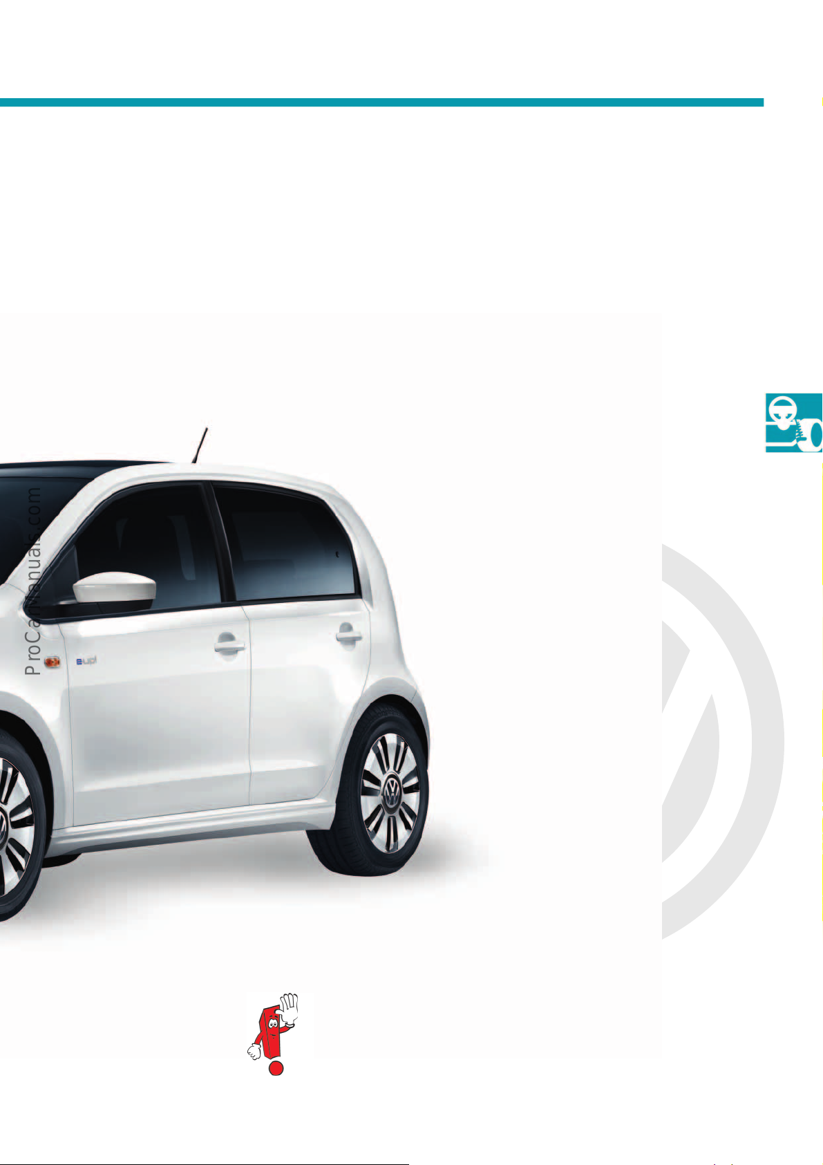
• City Emergency Brake (optional)
in Drive Pack Plus package
• Torsion beam rear axle
• Rear drum brakes
Further information can be found in Self-study Programme
no. 529 “The e-up! Running Gear and Power Transmission”.
15
Page 16
P
r
o
t
e
c
t
e
d
b
y
c
o
p
y
r
i
g
h
t
.
C
o
p
y
i
n
g
f
o
r
p
r
i
v
a
t
e
o
r
c
o
m
m
e
r
c
i
a
l
p
u
r
p
o
s
e
s
,
i
n
p
a
r
t
o
r
i
n
w
h
o
l
e
,
i
s
n
o
t
p
e
r
m
i
t
t
e
d
u
n
l
e
s
s
a
u
t
h
o
r
i
s
e
d
b
y
V
o
l
k
s
w
a
g
e
n
A
G
.
V
o
l
k
s
w
a
g
e
n
A
G
d
o
e
s
n
o
t
g
u
a
r
a
n
t
e
e
o
r
a
c
c
e
p
t
a
n
y
l
i
a
b
i
l
i
t
y
w
i
t
h
r
e
s
p
e
c
t
t
o
t
h
e
c
o
r
r
e
c
t
n
e
s
s
o
f
i
n
f
o
r
m
a
t
i
o
n
i
n
t
h
i
s
d
o
c
u
m
e
n
t
.
C
o
p
y
r
i
g
h
t
b
y
V
o
l
k
s
w
a
g
e
n
A
G
.
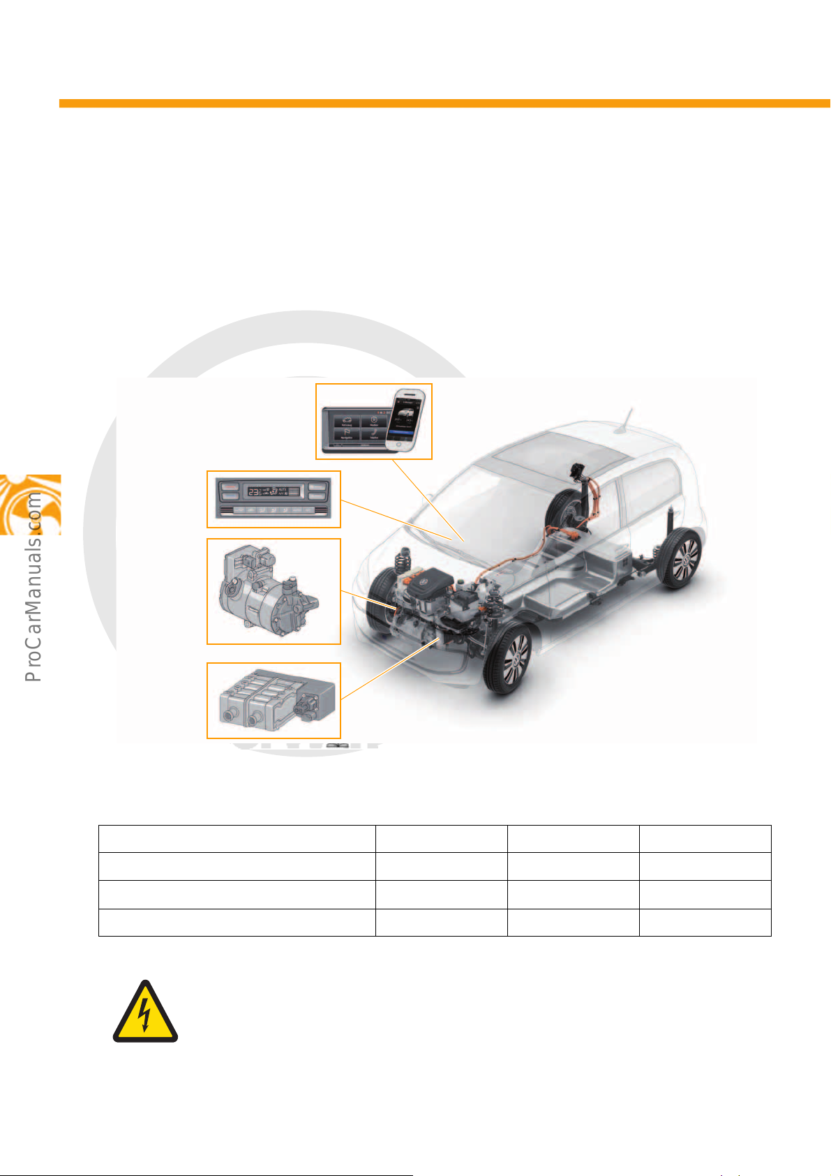
Heating and air conditioning
Smartphone app
and “maps + more”
High-voltage
heater
(PTC) Z115
s527_025
Electrical air
conditioner
compressor V470
Heater and air
conditioning
controls EX21
Overview of components
The heating and air conditioning systems contain some new components. Across all markets, a 1-zone Climatronic
is installed as series standard. The stationary air conditioning function is also new. It can be activated via a
smartphone app, the customer portal or via “maps + more”.
Other new components are:
• Electrical air conditioner compressor V470
• High-voltage heater (PTC) Z115
• Heater and air conditioning controls EX21
The selected driving mode affects the power of the electrical air conditioner compressor V470 and the
high-voltage heater (PTC) Z115:
16
Systems affected/driving modes Normal ECO ECO+
Electrical air conditioner compressor V470 Normal Reduced Deactivated
High-voltage heater (PTC) Z115 Normal Reduced Deactivated
Temperature indicator Normal Normal Deactivated
Caution! Hazardous electric voltage!
Before any work on the electrical air conditioner compressor V470 and the high-voltage heater
(PTC) Z115 are carried out, the high-voltage system must be certified as de-energised and the
refrigerant circuit drained.
Page 17
P
r
o
t
e
c
t
e
d
b
y
c
o
p
y
r
i
g
h
t
.
C
o
p
y
i
n
g
f
o
r
p
r
i
v
a
t
e
o
r
c
o
m
m
e
r
c
i
a
l
p
u
r
p
o
s
e
s
,
i
n
p
a
r
t
o
r
i
n
w
h
o
l
e
,
i
s
n
o
t
p
e
r
m
i
t
t
e
d
u
n
l
e
s
s
a
u
t
h
o
r
i
s
e
d
b
y
V
o
l
k
s
w
a
g
e
n
A
G
.
V
o
l
k
s
w
a
g
e
n
A
G
d
o
e
s
n
o
t
g
u
a
r
a
n
t
e
e
o
r
a
c
c
e
p
t
a
n
y
l
i
a
b
i
l
i
t
y
w
i
t
h
r
e
s
p
e
c
t
t
o
t
h
e
c
o
r
r
e
c
t
n
e
s
s
o
f
i
n
f
o
r
m
a
t
i
o
n
i
n
t
h
i
s
d
o
c
u
m
e
n
t
.
C
o
p
y
r
i
g
h
t
b
y
V
o
l
k
s
w
a
g
e
n
A
G
.
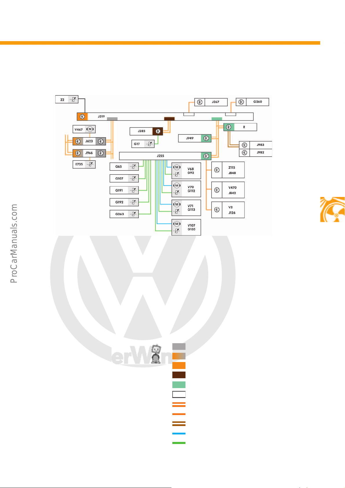
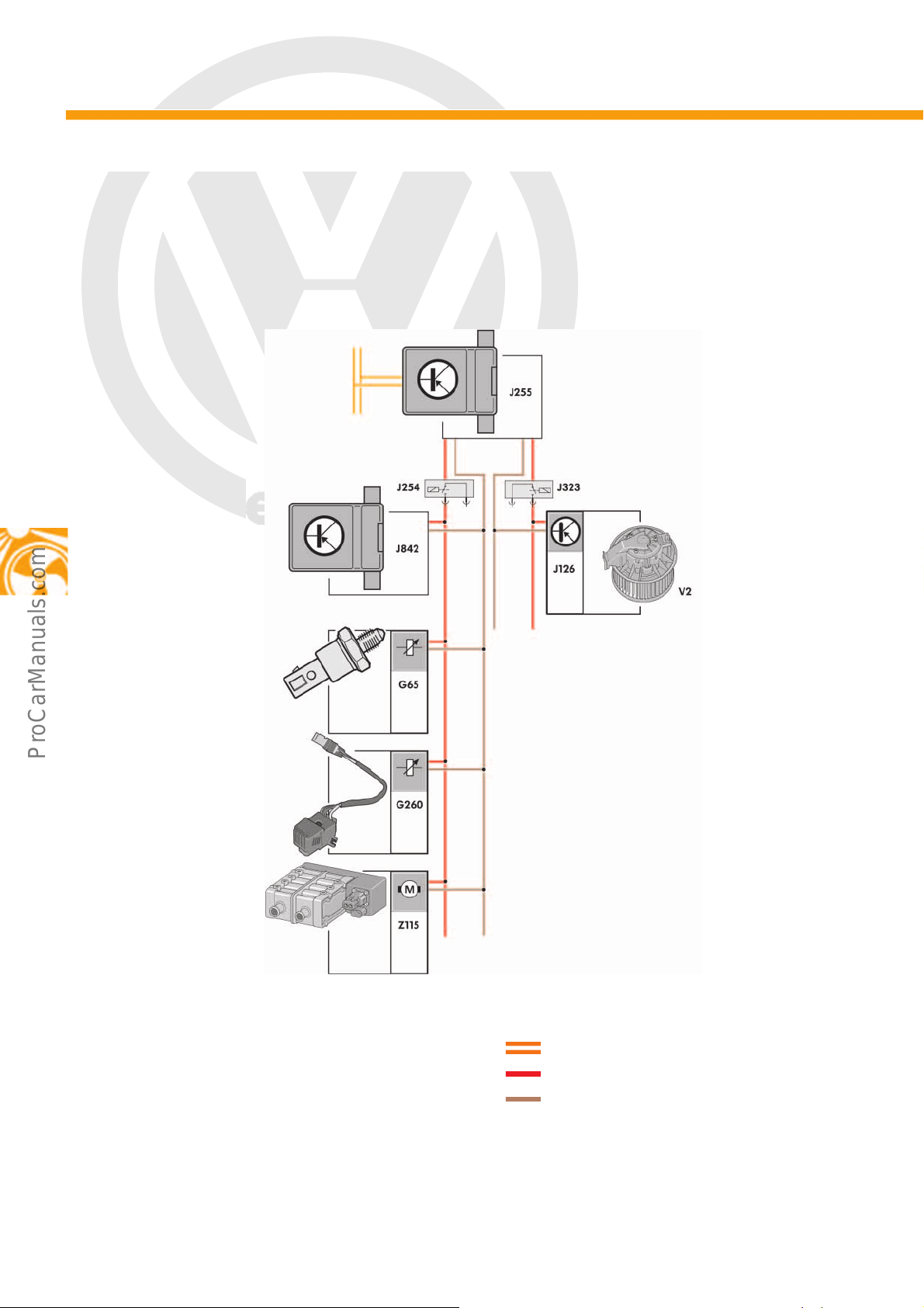
Climate control network plan
s527_026
Key
E735 Driving mode selection button
G17 Ambient temperature sensor
G65 High-pressure sender
G92 Potentiometer for temperature flap control motor
G107 Sunlight penetration photosensor
G112 Potentiometer for centre flap servomotor
G113 Potentiometer for air flow flap control motor
G135 Potentiometer for defroster flap control motor
G191 Centre vent temperature sender
G192 Footwell vent temperature sender
G260 Humidity sender for air conditioning system
G263 Evaporator output temperature sender
J126 Fresh air blower control unit
J255 Climatronic control unit
J285 Control unit in dash panel insert
J367 Battery monitor control unit
J519 Onboard supply control unit
J623 Engine (motor) control unit
J842 Control unit for air conditioning compressor
J848 High-voltage heater (PTC) control unit
J949 Emergency call module control unit and
J966 Charge voltage control unit for
J982 Portable navigation and infotainment system
communication unit
high-voltage battery
J983 Interface for portable navigation
and infotainment system
R Radio
V2 Fresh air blower
V68 Temperature flap control motor
V70 Centre flap control motor
V71 Air flow flap control motor
V107 Defroster flap control motor
V467 Coolant pump for high-temperature circuit
V470 Electrical air conditioner compressor
Z2 Heated windscreen
Z115 High-voltage heater (PTC)
Powertrain CAN data bus
Hybrid CAN data bus
Diagnostic CAN data bus
Dash panel insert CAN data bus
Convenience CAN data bus
LIN data bus
CAN data bus wire
LIN data bus wire
Unidirectional LIN data bus wire
Actuator line
Sensor line
17
Page 18
P
r
o
t
e
c
t
e
d
b
y
c
o
p
y
r
i
g
h
t
.
C
o
p
y
i
n
g
f
o
r
p
r
i
v
a
t
e
o
r
c
o
m
m
e
r
c
i
a
l
p
u
r
p
o
s
e
s
,
i
n
p
a
r
t
o
r
i
n
w
h
o
l
e
,
i
s
n
o
t
p
e
r
m
i
t
t
e
d
u
n
l
e
s
s
a
u
t
h
o
r
i
s
e
d
b
y
V
o
l
k
s
w
a
g
e
n
A
G
.
V
o
l
k
s
w
a
g
e
n
A
G
d
o
e
s
n
o
t
g
u
a
r
a
n
t
e
e
o
r
a
c
c
e
p
t
a
n
y
l
i
a
b
i
l
i
t
y
w
i
t
h
r
e
s
p
e
c
t
t
o
t
h
e
c
o
r
r
e
c
t
n
e
s
s
o
f
i
n
f
o
r
m
a
t
i
o
n
i
n
t
h
i
s
d
o
c
u
m
e
n
t
.
C
o
p
y
r
i
g
h
t
b
y
V
o
l
k
s
w
a
g
e
n
A
G
.
s527_006
High-voltage
connection
Low-voltage
connection
Control unit for air
conditioning compressor
J842
Electric motor
Compressor
Heating and air conditioning
s527_124
Fixed spiral
Rotating spiral
Refrigerant
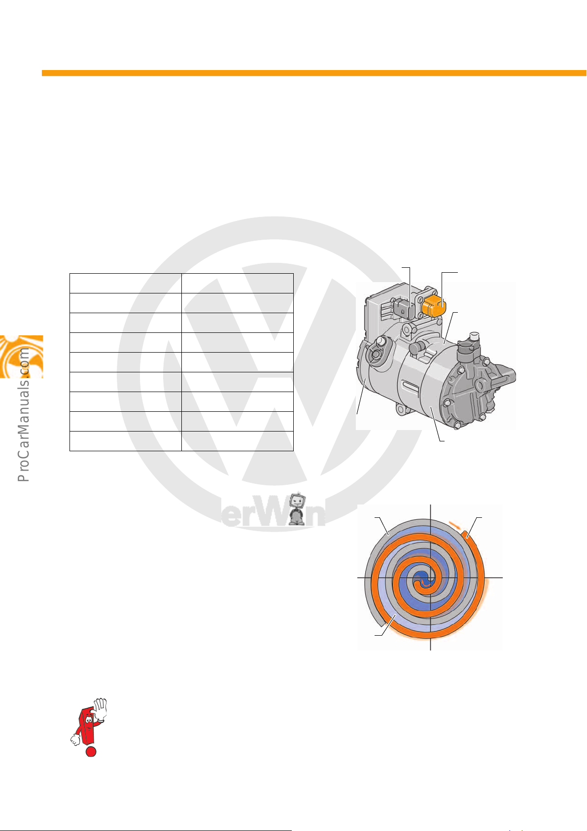
Electrical air conditioner compressor V470
The electrical air conditioner compressor V470 has been completely overhauled for the e-up!. The challenge was
to reduce the effects of the rotating masses in the air conditioner compressor both acoustically and in terms of
vibrations, as in an electric vehicle this noise is not covered by the electric drive. The electrical air conditioner
compressor V470 is installed at the front on the right of the electric drive. It is a scroll compressor and is intended
for use with the refrigerant R134a .
Technical data
Type Scroll compressor
Nominal voltage 374V
Rotational speed 800 to 8600 rpm
Power consumption 3.6kW
Operating temperature – 10 °C to + 120 °C
Weight 6kg
Refrigerant R134a
Refrigerant oil SP-A2
Communication LIN bus
Scroll compressor
The compressor consists of a fixed and a rotating
spiral which intermesh.
The rotating spiral is driven by the electric motor in an
eccentric motion, and moves on a circular path. This
eccentric movement allows the spirals to form several,
increasingly small chambers in which the coolant is
compressed.
18
Further information on the design and function of the electrical air conditioner compressor can be
found in Self-study Programme No. 525 “The Jetta Hybrid”.
Page 19
P
r
o
t
e
c
t
e
d
b
y
c
o
p
y
r
i
g
h
t
.
C
o
p
y
i
n
g
f
o
r
p
r
i
v
a
t
e
o
r
c
o
m
m
e
r
c
i
a
l
p
u
r
p
o
s
e
s
,
i
n
p
a
r
t
o
r
i
n
w
h
o
l
e
,
i
s
n
o
t
p
e
r
m
i
t
t
e
d
u
n
l
e
s
s
a
u
t
h
o
r
i
s
e
d
b
y
V
o
l
k
s
w
a
g
e
n
A
G
.
V
o
l
k
s
w
a
g
e
n
A
G
d
o
e
s
n
o
t
g
u
a
r
a
n
t
e
e
o
r
a
c
c
e
p
t
a
n
y
l
i
a
b
i
l
i
t
y
w
i
t
h
r
e
s
p
e
c
t
t
o
t
h
e
c
o
r
r
e
c
t
n
e
s
s
o
f
i
n
f
o
r
m
a
t
i
o
n
i
n
t
h
i
s
d
o
c
u
m
e
n
t
.
C
o
p
y
r
i
g
h
t
b
y
V
o
l
k
s
w
a
g
e
n
A
G
.
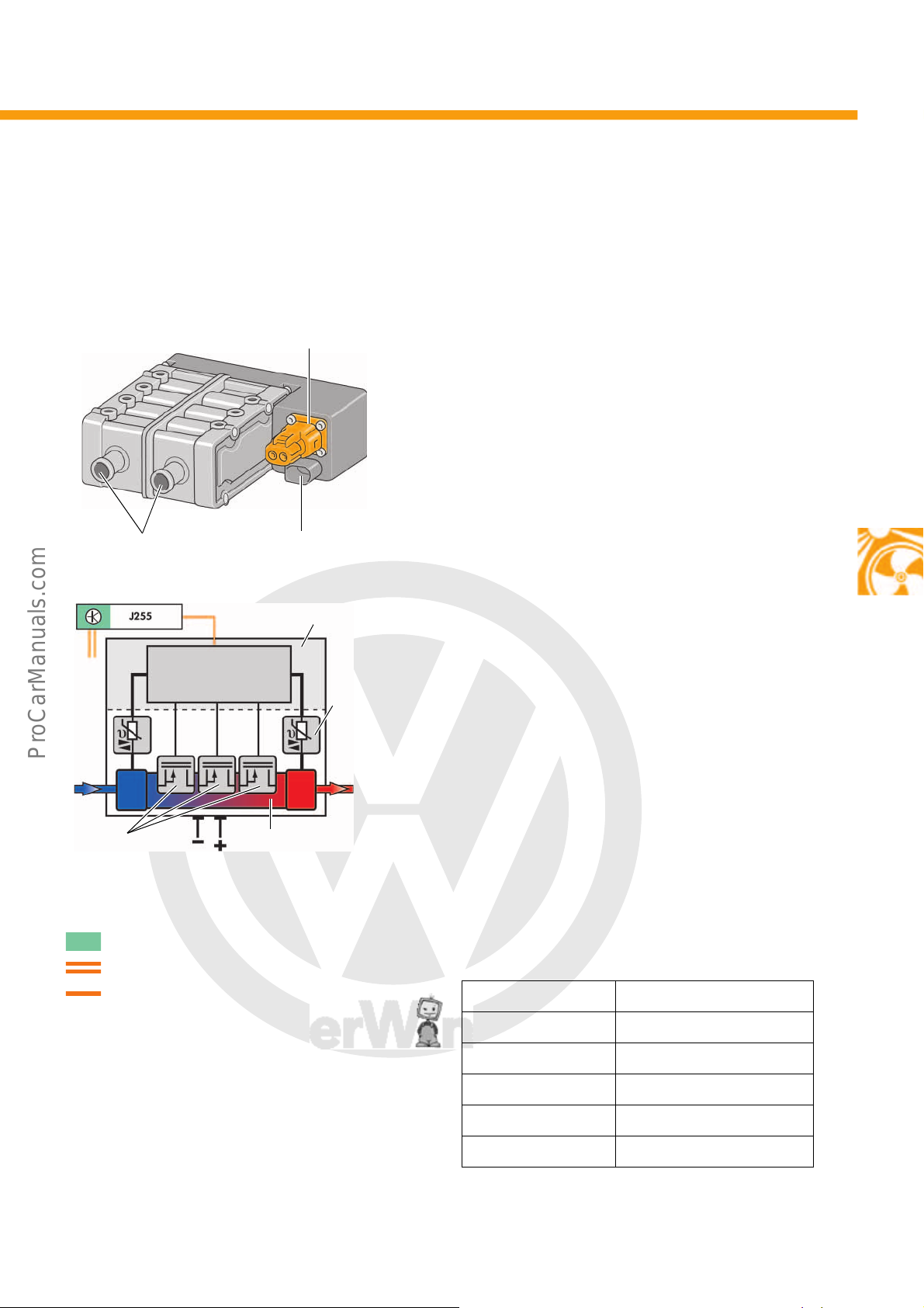
High-voltage heater (PTC) Z115
s527_008
12 V interface to onboard
supply
Coolant connections
High-voltage connection
High-voltage heater
(PTC) control unit J848
Temperature
sensor
High-voltage
heater element
Heating circuits
1 to 3
Actuation of LIN interface
s527_010
The high-voltage heater (PTC) Z115 heats the coolant in the coolant circuit, as there is no combustion engine to
heat up the coolant.
Design
The high-voltage heater (PTC) Z115 is connected to
the high-voltage system via a high-voltage wire.
The 12-volt interface to the onboard supply ensures
communication with the Climatronic control unit J255
via the LIN data bus.
Key
J255 Climatronic control unit
Convenience CAN data bus
CAN data bus wire
LIN data bus wire
Function
The Climatronic control unit J255 actuates the highvoltage heater (PTC) Z115. The input and output
temperature of the coolant are both measured by a
temperature sensor. It specifies the required heat
output within a range from 0 to 100 %. The
requirement is converted into control signals for the
heating circuits by the high-voltage heater (PTC)
control unit J848. The high-voltage heater (PTC) Z115
has three heating circuits with connected PTC
elements. Heating circuits 1 and 2 are actuated with a
pulse-width modulated signal (PWM). Heating circuit
3 is switched on or off depending on the required
switching level.
Technical data
Power 5.5kW
Actuation 0-100%
Input voltage 180-374V
Max. input current 30A
Interfaces LIN 2.0 with self-diagnosis
AC/DC insulation 100MΩ
19
Page 20
P
r
o
t
e
c
t
e
d
b
y
c
o
p
y
r
i
g
h
t
.
C
o
p
y
i
n
g
f
o
r
p
r
i
v
a
t
e
o
r
c
o
m
m
e
r
c
i
a
l
p
u
r
p
o
s
e
s
,
i
n
p
a
r
t
o
r
i
n
w
h
o
l
e
,
i
s
n
o
t
p
e
r
m
i
t
t
e
d
u
n
l
e
s
s
a
u
t
h
o
r
i
s
e
d
b
y
V
o
l
k
s
w
a
g
e
n
A
G
.
V
o
l
k
s
w
a
g
e
n
A
G
d
o
e
s
n
o
t
g
u
a
r
a
n
t
e
e
o
r
a
c
c
e
p
t
a
n
y
l
i
a
b
i
l
i
t
y
w
i
t
h
r
e
s
p
e
c
t
t
o
t
h
e
c
o
r
r
e
c
t
n
e
s
s
o
f
i
n
f
o
r
m
a
t
i
o
n
i
n
t
h
i
s
d
o
c
u
m
e
n
t
.
C
o
p
y
r
i
g
h
t
b
y
V
o
l
k
s
w
a
g
e
n
A
G
.
Heating and air conditioning
Buttons for air distribution AC buttonDefrost
Air
recirculation
Heated windscreen
switch E180 with
indicator LED
Display for status of
Climatronic
Buttons for fresh air blower Buttons for temperature
control
s527_012
Button for automatic adjustment of
temperature and ventilation
s527_004
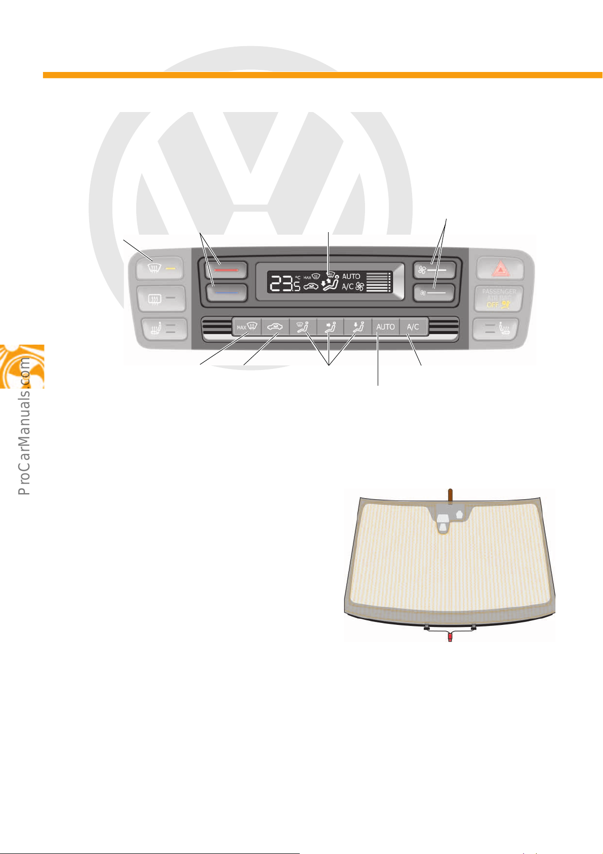
Heater and air conditioning controls EX21
All controls used to adjust the temperature and ventilation have been integrated into one operating unit.
Heated windscreen Z2
There are two ways to activate the windscreen
heater:
1. Manual activation using the heated windscreen
switch E180
2. Automatic activation using the Climatronic control
unit J255
20
Page 21
P
r
o
t
e
c
t
e
d
b
y
c
o
p
y
r
i
g
h
t
.
C
o
p
y
i
n
g
f
o
r
p
r
i
v
a
t
e
o
r
c
o
m
m
e
r
c
i
a
l
p
u
r
p
o
s
e
s
,
i
n
p
a
r
t
o
r
i
n
w
h
o
l
e
,
i
s
n
o
t
p
e
r
m
i
t
t
e
d
u
n
l
e
s
s
a
u
t
h
o
r
i
s
e
d
b
y
V
o
l
k
s
w
a
g
e
n
A
G
.
V
o
l
k
s
w
a
g
e
n
A
G
d
o
e
s
n
o
t
g
u
a
r
a
n
t
e
e
o
r
a
c
c
e
p
t
a
n
y
l
i
a
b
i
l
i
t
y
w
i
t
h
r
e
s
p
e
c
t
t
o
t
h
e
c
o
r
r
e
c
t
n
e
s
s
o
f
i
n
f
o
r
m
a
t
i
o
n
i
n
t
h
i
s
d
o
c
u
m
e
n
t
.
C
o
p
y
r
i
g
h
t
b
y
V
o
l
k
s
w
a
g
e
n
A
G
.
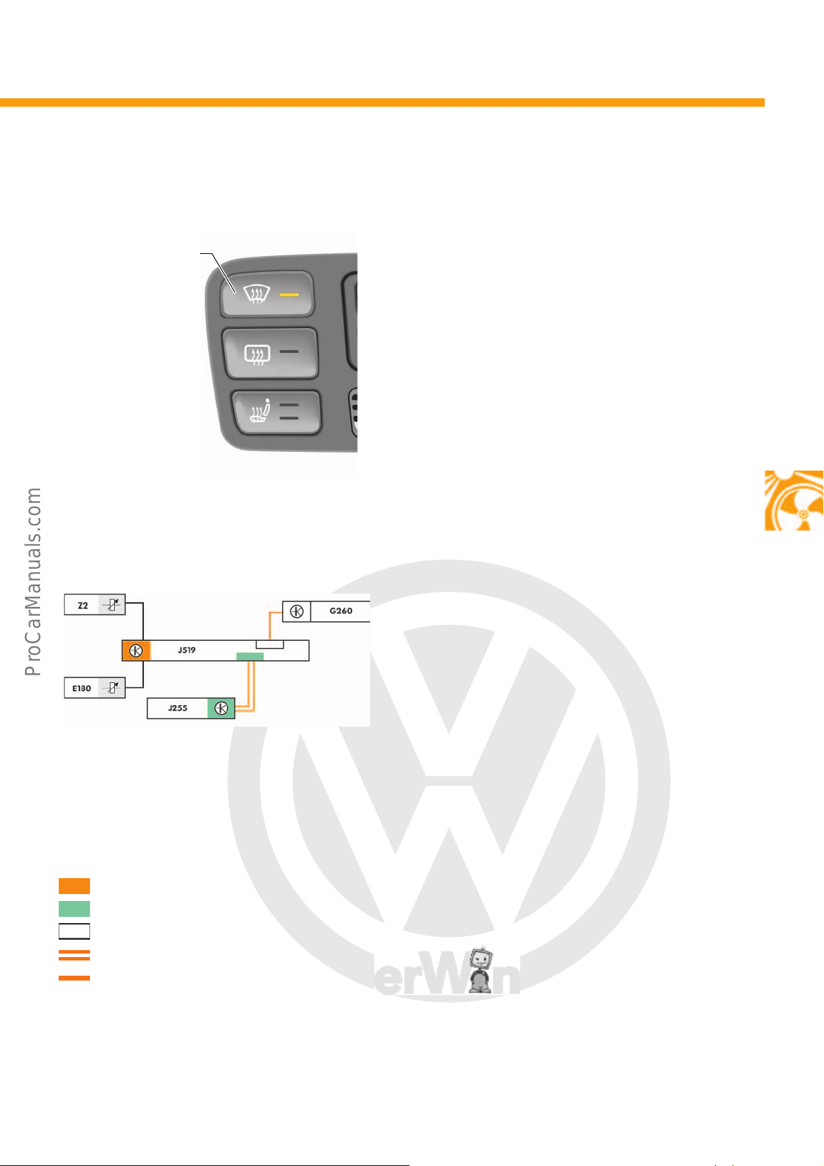
Manual activation using switch
Heated windscreen
switch E180 with
indicator LED
s527_014
s527_126
Automatic activation
Key
E180 Heated windscreen switch
G260 Humidity sender for air conditioning system
J255 Climatronic control unit
J519 Climatronic control unit
Z2 Heated windscreen
Diagnostic CAN data bus
Convenience CAN data bus
LIN data bus
CAN data bus wire
LIN data bus wire
The windscreen heater is activated with the switch for
windscreen heater E180 , which is connected to the
onboard supply control unit J519.
The heating duration is limited. Shut-off occurs after a
maximum of 4 minutes via the onboard supply control
unit J519. If necessary, the heating can be switched
off immediately using the heated windscreen switch
E180. The windscreen heater can also be switched off
as part of load management.
The windscreen heater can also be activated by the
Climatronic control unit J255 if the dew point exceeds
a defined value. The dew point is the temperature at
which the humidity condenses into water droplets.
The temperature and humidity on the windscreen are
registered by the humidity sender for the air
conditioning system G260. The windscreen heater is
then switched on automatically, if necessary.
This only takes place in “AUTO” mode and can be
more economical in terms of energy than switching to
the high-voltage compressor for the air conditioning
system. This function can be interrupted at any time by
pressing the heated windscreen switch E180.
21
Page 22
P
r
o
t
e
c
t
e
d
b
y
c
o
p
y
r
i
g
h
t
.
C
o
p
y
i
n
g
f
o
r
p
r
i
v
a
t
e
o
r
c
o
m
m
e
r
c
i
a
l
p
u
r
p
o
s
e
s
,
i
n
p
a
r
t
o
r
i
n
w
h
o
l
e
,
i
s
n
o
t
p
e
r
m
i
t
t
e
d
u
n
l
e
s
s
a
u
t
h
o
r
i
s
e
d
b
y
V
o
l
k
s
w
a
g
e
n
A
G
.
V
o
l
k
s
w
a
g
e
n
A
G
d
o
e
s
n
o
t
g
u
a
r
a
n
t
e
e
o
r
a
c
c
e
p
t
a
n
y
l
i
a
b
i
l
i
t
y
w
i
t
h
r
e
s
p
e
c
t
t
o
t
h
e
c
o
r
r
e
c
t
n
e
s
s
o
f
i
n
f
o
r
m
a
t
i
o
n
i
n
t
h
i
s
d
o
c
u
m
e
n
t
.
C
o
p
y
r
i
g
h
t
b
y
V
o
l
k
s
w
a
g
e
n
A
G
.
Heating and air conditioning
s527_027
Stationary air conditioning
The e-up! offers the driver the option of stationary air conditioning. The temperature inside the vehicle can be
controlled remotely or via a timer. Stationary air conditioning is independent of the selected driving mode. It is not
possible to operate the air conditioning system using the controls during stationary air conditioning. The LED for the
AC button lights up and the buttons are not active. When the vehicle is made ready for driving, the stationary air
conditioning is deactivated and the air conditioning system can only be operated using the controls in the vehicle.
The e-up! has two stationary air conditioning variants:
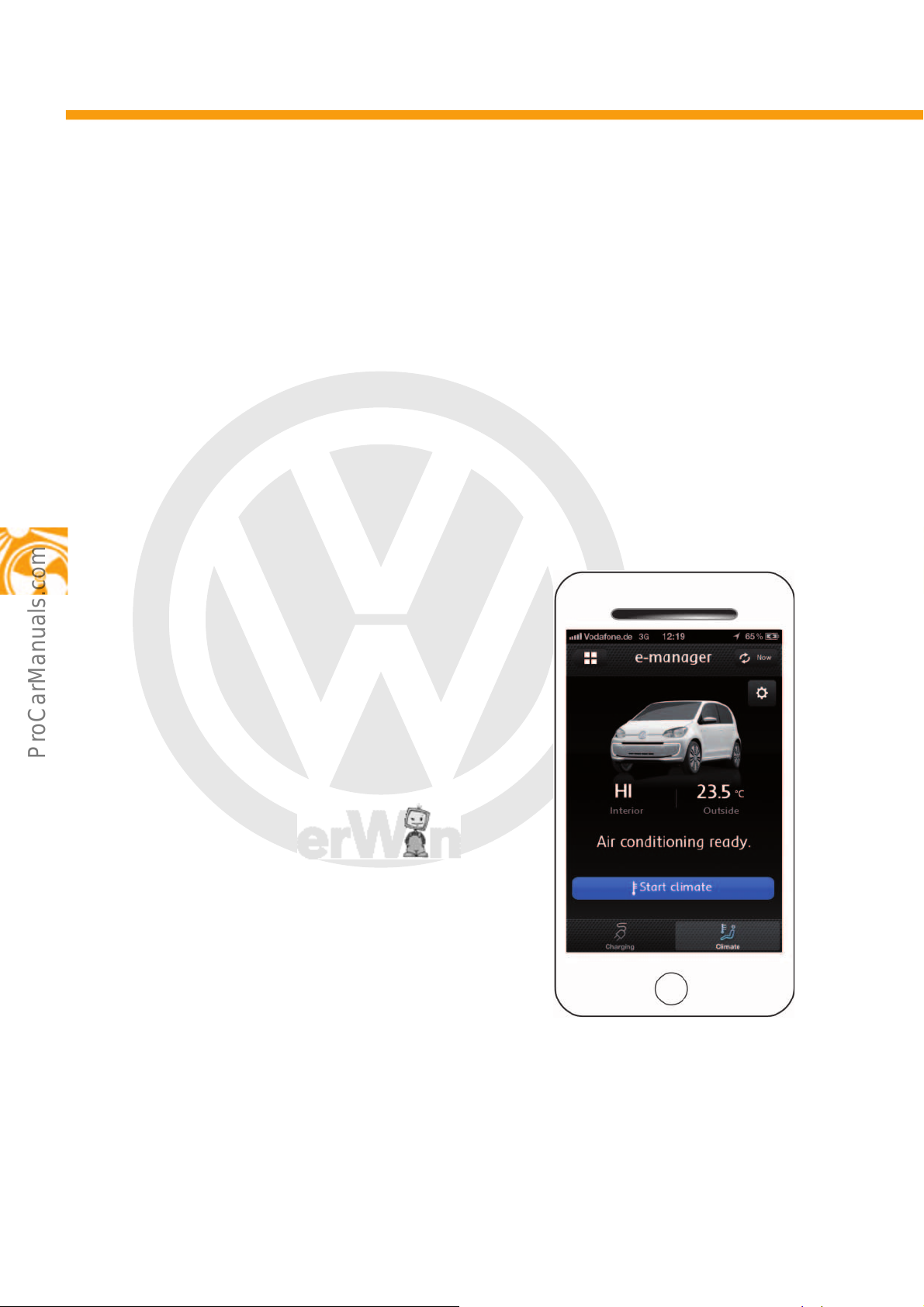
1. Instant air conditioning via a smartphone app or the customer portal (further information on the app and the
customer portal can be found in the section Car-Net, from page 54).
2. Timer program via “maps + more”.
Instant air conditioning
The stationary air conditioning can be activated as
immediate air conditioning via the smartphone app or
the customer portal. Both of these can be used to
regulate the temperature inside the vehicle. The driver
can enter a preferred temperature between 16°C
and 29 °C.
When in the modes “Low” and “High”, the Climatronic
control unit J255 controls a temperature range
between Low = 15.5 °C and High = 30.5 °C. The
maximum run time for the air conditioning is 30
minutes when charging and 10 minutes maximum
when in high-voltage battery operation. Instant air
conditioning via the smartphone app is possible when
the high-voltage battery has a charging capacity of
20% or more.
22
Page 23
P
r
o
t
e
c
t
e
d
b
y
c
o
p
y
r
i
g
h
t
.
C
o
p
y
i
n
g
f
o
r
p
r
i
v
a
t
e
o
r
c
o
m
m
e
r
c
i
a
l
p
u
r
p
o
s
e
s
,
i
n
p
a
r
t
o
r
i
n
w
h
o
l
e
,
i
s
n
o
t
p
e
r
m
i
t
t
e
d
u
n
l
e
s
s
a
u
t
h
o
r
i
s
e
d
b
y
V
o
l
k
s
w
a
g
e
n
A
G
.
V
o
l
k
s
w
a
g
e
n
A
G
d
o
e
s
n
o
t
g
u
a
r
a
n
t
e
e
o
r
a
c
c
e
p
t
a
n
y
l
i
a
b
i
l
i
t
y
w
i
t
h
r
e
s
p
e
c
t
t
o
t
h
e
c
o
r
r
e
c
t
n
e
s
s
o
f
i
n
f
o
r
m
a
t
i
o
n
i
n
t
h
i
s
d
o
c
u
m
e
n
t
.
C
o
p
y
r
i
g
h
t
b
y
V
o
l
k
s
w
a
g
e
n
A
G
.
s527_020
Departure time 1
Departure time 2
Departure time 3
Charging locations
Messages present
e-Manager
e-Manager Settings
s527_022
Charging location: standard
Departure Repetition
SaveCancel
Mo Tue We Thu
Fri Sat Sun
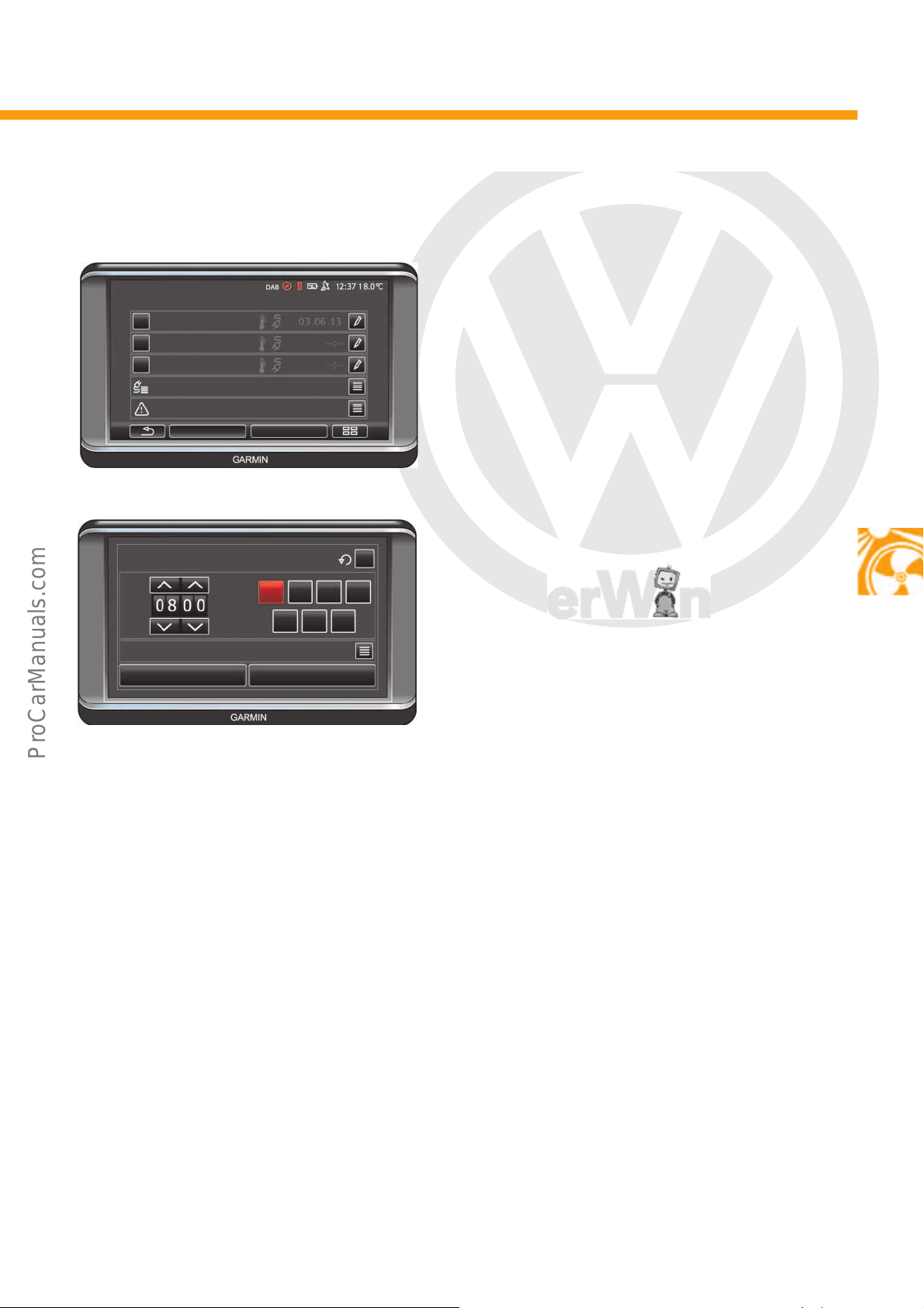
Timer program
Stationary air conditioning can be activated by means
of timer programming via “maps + more”. If air
conditioning has been pre-selected for the time of
departure, the Climatronic control unit J255 is
activated by the high-voltage battery charger control
unit J1050 one hour before departure. It calculates
the required duration for air conditioning, sends the
value to the control unit for high-voltage battery
charging unit J1050 and then becomes inactive
again. Once the calculated start time for the air
conditioning has been reached, the Climatronic
control unit J255 is reactivated and stationary air
conditioning begins. The maximum power which can
be consumed for stationary air conditioning is limited
by the charge voltage control unit for high-voltage
battery J966 to 3.3 kW.
If stationary air conditioning was activated via “maps
+ more”, any other timer entries which may still be
stored are ignored. Changes made via “maps +
more” are not synchronised with the smartphone.
Timer programming in charging mode
The stationary air conditioning only starts if the highvoltage battery has a charge level of at least 20 %.
Charging the high-voltage battery is limited when the
stationary air conditioning is running. Charging and
air conditioning cannot take place simultaneously
when charging with alternate current (AC charging).
Air conditioning can only take place during the
charging process when charging with direct current
(DC charging). Once the charging station has been
switched off, the stationary air conditioning also
switches off.
Timer programming in
high-voltage battery mode
In high-voltage battery mode, the stationary air
conditioning starts 10 minutes before the
programmed time of departure. If the high-voltage
battery’s minimum charging capacity of 20% has not
been reached, stationary air conditioning will not
start. The minimum charging capacity can be set by
the customer, but may never be lower than 20 %.
23
Page 24
P
r
o
t
e
c
t
e
d
b
y
c
o
p
y
r
i
g
h
t
.
C
o
p
y
i
n
g
f
o
r
p
r
i
v
a
t
e
o
r
c
o
m
m
e
r
c
i
a
l
p
u
r
p
o
s
e
s
,
i
n
p
a
r
t
o
r
i
n
w
h
o
l
e
,
i
s
n
o
t
p
e
r
m
i
t
t
e
d
u
n
l
e
s
s
a
u
t
h
o
r
i
s
e
d
b
y
V
o
l
k
s
w
a
g
e
n
A
G
.
V
o
l
k
s
w
a
g
e
n
A
G
d
o
e
s
n
o
t
g
u
a
r
a
n
t
e
e
o
r
a
c
c
e
p
t
a
n
y
l
i
a
b
i
l
i
t
y
w
i
t
h
r
e
s
p
e
c
t
t
o
t
h
e
c
o
r
r
e
c
t
n
e
s
s
o
f
i
n
f
o
r
m
a
t
i
o
n
i
n
t
h
i
s
d
o
c
u
m
e
n
t
.
C
o
p
y
r
i
g
h
t
b
y
V
o
l
k
s
w
a
g
e
n
A
G
.
Heating and air conditioning
s527_024
Convenience CAN data
bus
Actuation of components with ignition “off”
If the stationary air conditioning has been activated via “maps + more”, the smartphone app or the customer
portal, the high-voltage components for the heating and air conditioning will work even if the ignition is not on. The
high-voltage components are supplied with a current via the Climatronic relay J254 and the blower relay J323.
Key
G65 High-pressure sender
G260 Humidity sender for air conditioning system
J126 Fresh air blower control unit
J254 Climatronic relay
J255 Climatronic control unit
J323 Blower relay
J842 Control unit for air conditioning compressor
V2 Fresh air blower
Z115 High-voltage heater (PTC)
CAN data bus wire
Positive
Earth
24
Page 25
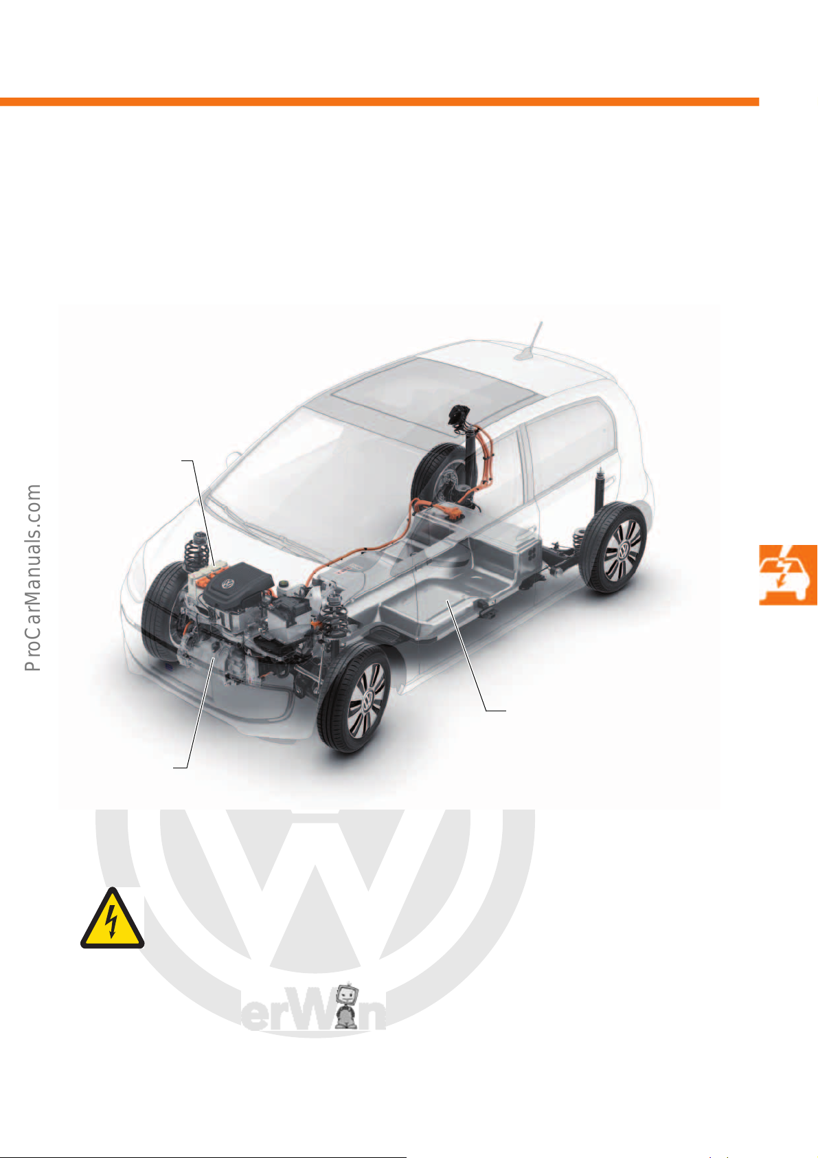
P
r
o
t
e
c
t
e
d
b
y
c
o
p
y
r
i
g
h
t
.
C
o
p
y
i
n
g
f
o
r
p
r
i
v
a
t
e
o
r
c
o
m
m
e
r
c
i
a
l
p
u
r
p
o
s
e
s
,
i
n
p
a
r
t
o
r
i
n
w
h
o
l
e
,
i
s
n
o
t
p
e
r
m
i
t
t
e
d
u
n
l
e
s
s
a
u
t
h
o
r
i
s
e
d
b
y
V
o
l
k
s
w
a
g
e
n
A
G
.
V
o
l
k
s
w
a
g
e
n
A
G
d
o
e
s
n
o
t
g
u
a
r
a
n
t
e
e
o
r
a
c
c
e
p
t
a
n
y
l
i
a
b
i
l
i
t
y
w
i
t
h
r
e
s
p
e
c
t
t
o
t
h
e
c
o
r
r
e
c
t
n
e
s
s
o
f
i
n
f
o
r
m
a
t
i
o
n
i
n
t
h
i
s
d
o
c
u
m
e
n
t
.
C
o
p
y
r
i
g
h
t
b
y
V
o
l
k
s
w
a
g
e
n
A
G
.
High-voltage system
Three-phase current
drive VX54
High-voltage battery 1
AX2
Power and control
electronics for electric
drive JX1
s527_029
Overview of the high-voltage system
The e-up! consists of a three-phase current drive VX54, power and control electronics for electric drive JX1 and a
high-voltage battery 1 AX2. The components are in a space-saving arrangement so that there are no limitations
concerning the space available and operation.
Caution! Hazardous electric voltage!
Please note that work on the hybrid vehicle performed near or on high-voltage components
may be carried out only by qualified and therefore authorised Volkswagen high-voltage
technicians. Improper handling of high-voltage systems involves a risk of fatal injury due to
electric shock. AC voltages of 25 volts or more and DC voltages of 60 volts or more are
dangerous for humans. Please observe the safety information in the service literature,
the diagnostic tester and on the vehicle itself.
25
Page 26
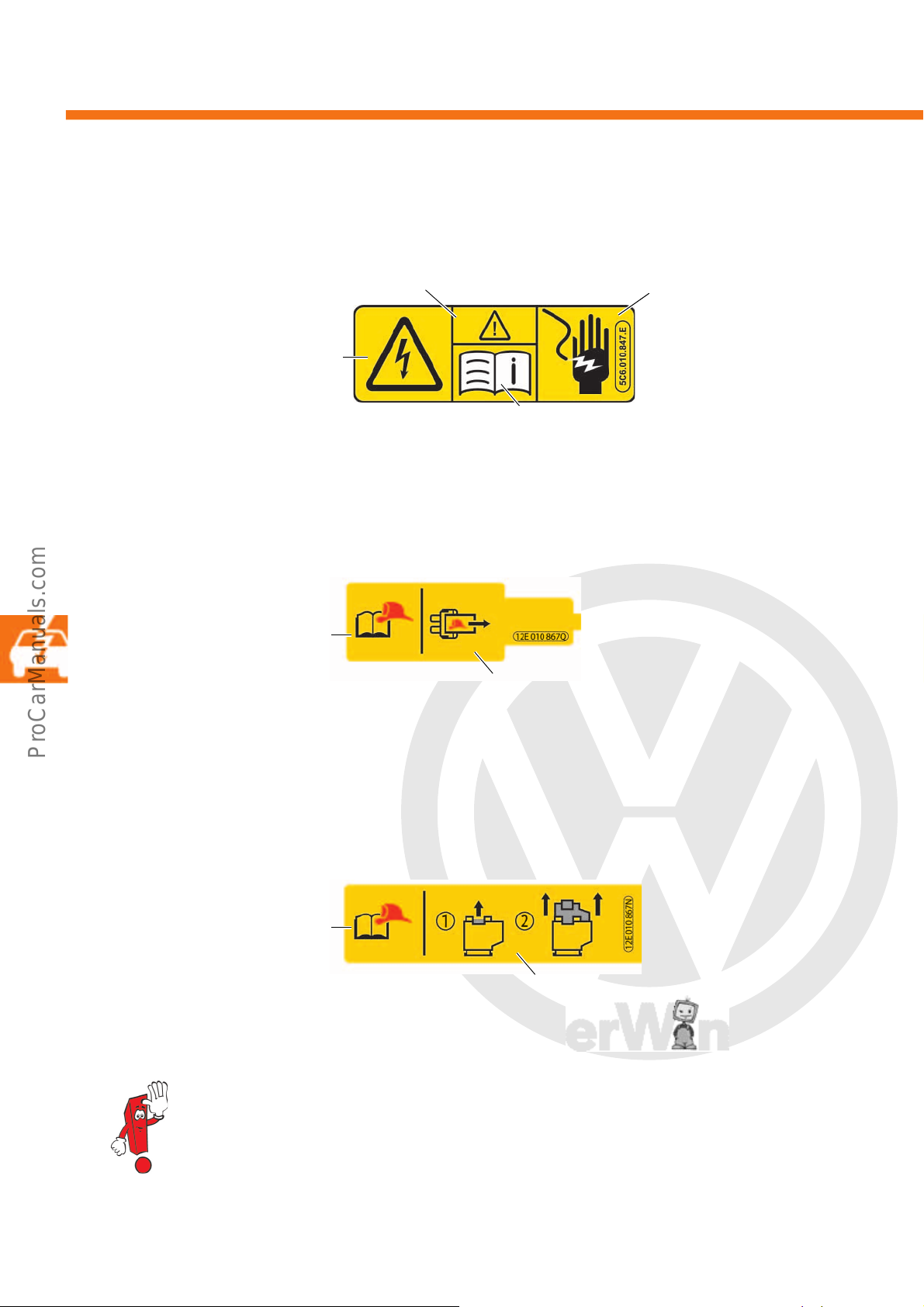
P
r
o
t
e
c
t
e
d
b
y
c
o
p
y
r
i
g
h
t
.
C
o
p
y
i
n
g
f
o
r
p
r
i
v
a
t
e
o
r
c
o
m
m
e
r
c
i
a
l
p
u
r
p
o
s
e
s
,
i
n
p
a
r
t
o
r
i
n
w
h
o
l
e
,
i
s
n
o
t
p
e
r
m
i
t
t
e
d
u
n
l
e
s
s
a
u
t
h
o
r
i
s
e
d
b
y
V
o
l
k
s
w
a
g
e
n
A
G
.
V
o
l
k
s
w
a
g
e
n
A
G
d
o
e
s
n
o
t
g
u
a
r
a
n
t
e
e
o
r
a
c
c
e
p
t
a
n
y
l
i
a
b
i
l
i
t
y
w
i
t
h
r
e
s
p
e
c
t
t
o
t
h
e
c
o
r
r
e
c
t
n
e
s
s
o
f
i
n
f
o
r
m
a
t
i
o
n
i
n
t
h
i
s
d
o
c
u
m
e
n
t
.
C
o
p
y
r
i
g
h
t
b
y
V
o
l
k
s
w
a
g
e
n
A
G
.
High-voltage system
Warning of dangerous electrical
voltage as per DIN 4844-2 (BGV A8)
Warning of a danger area as per
DIN 4844-2 (BGV A8)
Information:
Observe the instruction manual as per
DIN 4844-2 (BGV A8)
Warning against
touching live parts
s527_028
s527_030
Observe the instructions on the
rescue data sheet
In an emergency, pull out the fuse with the rescue disconnection symbol. Pulling the
fuse out will interrupt the voltage supply to the battery regulation control unit J840 in
the high-voltage battery 1 AX2.
s527_032
Push up the plug lock and the plug and pull out. Opening the maintenance connector
for high-voltage system TW will interrupt the pilot line and voltage supply to the
battery regulation control unit J840 in the high-voltage battery 1 AX2.
Observe the instructions on the
rescue data sheet
Warning signs
Warning on the front lock carrier (bonnet)
Information: rescue disconnection point in passenger compartment
The rescue disconnection point 1 for the emergency services is located in the interior of the vehicle on the fuse
carrier of the left A-pillar.
Information: rescue disconnection point in motor compartment
The rescue disconnection point 2 for the emergency services is located in the motor compartment underneath the
cover on the left facing the direction of travel.
The high-voltage system is deactivated if the airbag or belt tensioner are triggered. Please observe the
instructions on the rescue data sheet.
26
Page 27
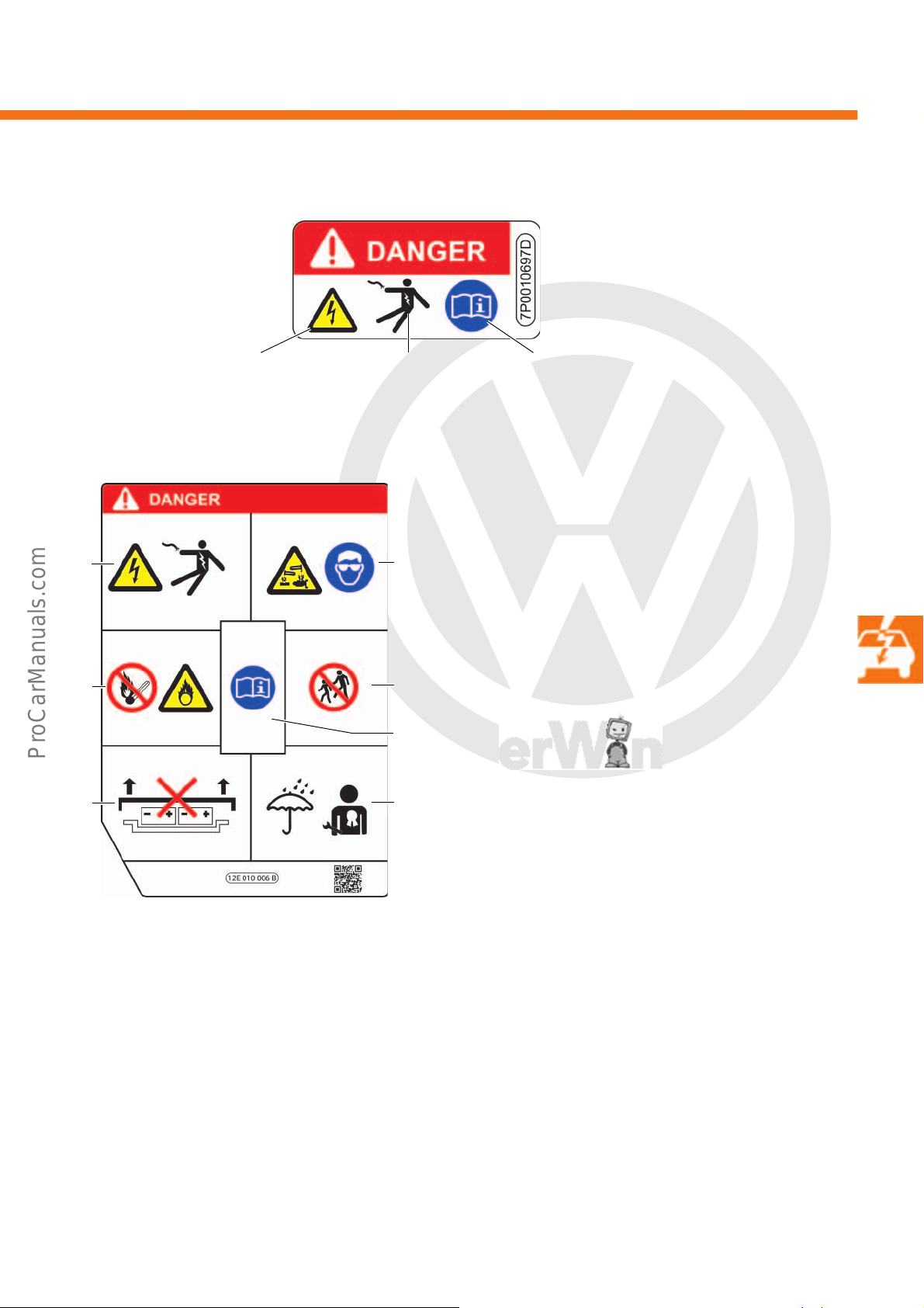
P
r
o
t
e
c
t
e
d
b
y
c
o
p
y
r
i
g
h
t
.
C
o
p
y
i
n
g
f
o
r
p
r
i
v
a
t
e
o
r
c
o
m
m
e
r
c
i
a
l
p
u
r
p
o
s
e
s
,
i
n
p
a
r
t
o
r
i
n
w
h
o
l
e
,
i
s
n
o
t
p
e
r
m
i
t
t
e
d
u
n
l
e
s
s
a
u
t
h
o
r
i
s
e
d
b
y
V
o
l
k
s
w
a
g
e
n
A
G
.
V
o
l
k
s
w
a
g
e
n
A
G
d
o
e
s
n
o
t
g
u
a
r
a
n
t
e
e
o
r
a
c
c
e
p
t
a
n
y
l
i
a
b
i
l
i
t
y
w
i
t
h
r
e
s
p
e
c
t
t
o
t
h
e
c
o
r
r
e
c
t
n
e
s
s
o
f
i
n
f
o
r
m
a
t
i
o
n
i
n
t
h
i
s
d
o
c
u
m
e
n
t
.
C
o
p
y
r
i
g
h
t
b
y
V
o
l
k
s
w
a
g
e
n
A
G
.
Warning on all high-voltage components
Warning against dangerous electrical
voltage as per DIN 4844-2 (BGV A8)
Instruction markers:
Observe the instruction manual as per
DIN 4844-2 (BGV A8)
s527_034
Warning against touching live
parts
*
1
3
6
2
4
7
5
* The note on the high-voltage battery may vary
by country.
s527_036
Information on the high-voltage battery
1 High voltages can result in severe injury or even
death. Never touch battery terminals with fingers,
tools, jewellery or other objects made of metal.
2 The high-voltage battery contains hazardous fluid
and solid substances. In the event of outgassing,
severe chemical burns and blindness could result.
When working on the high-voltage battery,
suitable eye protection and protective clothing
must be worn to prevent skin and eye contact with
battery acid. If skin or eye contact with battery
acid occurs, the areas affected must be rinsed for
at least 15 minutes using clean fresh water, and a
doctor should be consulted immediately.
3 The high-voltage battery is flammable. The high-
voltage battery must never be exposed to fire,
sparks or naked flames. The high-voltage battery
must always be handled with caution to prevent
any damage or acid discharge.
4 Always keep the high-voltage battery away from
children.
5 More detailed information and warnings can be
found in the owner's manual and in the workshop
manual.
6 Improper handling of the high-voltage battery can
result in severe injury or even death. Do not
remove the high-voltage battery or its cover under
any circumstances. Never make changes to the
high-voltage battery.
7 The high-voltage battery must not come into con-
tact with water or other fluids when opened. Fluids
can cause short circuits, electric shocks and fires.
27
Page 28
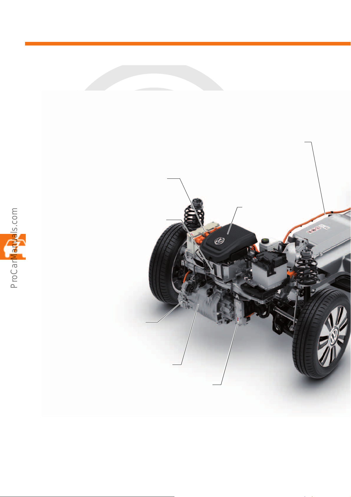
P
r
o
t
e
c
t
e
d
b
y
c
o
p
y
r
i
g
h
t
.
C
o
p
y
i
n
g
f
o
r
p
r
i
v
a
t
e
o
r
c
o
m
m
e
r
c
i
a
l
p
u
r
p
o
s
e
s
,
i
n
p
a
r
t
o
r
i
n
w
h
o
l
e
,
i
s
n
o
t
p
e
r
m
i
t
t
e
d
u
n
l
e
s
s
a
u
t
h
o
r
i
s
e
d
b
y
V
o
l
k
s
w
a
g
e
n
A
G
.
V
o
l
k
s
w
a
g
e
n
A
G
d
o
e
s
n
o
t
g
u
a
r
a
n
t
e
e
o
r
a
c
c
e
p
t
a
n
y
l
i
a
b
i
l
i
t
y
w
i
t
h
r
e
s
p
e
c
t
t
o
t
h
e
c
o
r
r
e
c
t
n
e
s
s
o
f
i
n
f
o
r
m
a
t
i
o
n
i
n
t
h
i
s
d
o
c
u
m
e
n
t
.
C
o
p
y
r
i
g
h
t
b
y
V
o
l
k
s
w
a
g
e
n
A
G
.
High-voltage system
Charging unit 1 for high-voltage battery AX4; 3.6 kW
with control unit for high-voltage battery charging
unit J1050
Three-phase current drive VX54
Electrical air conditioner compressor V470
with control unit for air conditioning
compressor J842
High-voltage heater (PTC) Z115
with high-voltage heater (PTC) control unit J848
High-voltage wire 1 charging power
distributor/high-voltage charging socket P18
Power and control electronics for electric drive JX1
with electric drive control unit J841
Engine (motor) control unit
J623, under the cover
Location of high-voltage components
28
Page 29
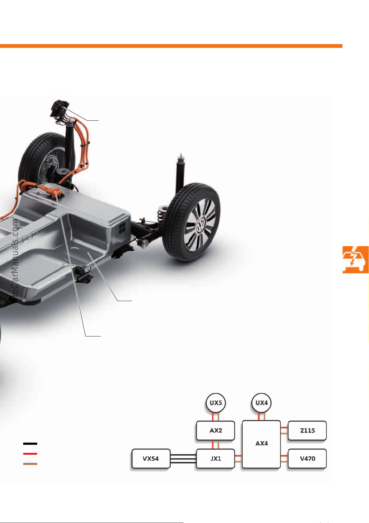
P
r
o
t
e
c
t
e
d
b
y
c
o
p
y
r
i
g
h
t
.
C
o
p
y
i
n
g
f
o
r
p
r
i
v
a
t
e
o
r
c
o
m
m
e
r
c
i
a
l
p
u
r
p
o
s
e
s
,
i
n
p
a
r
t
o
r
i
n
w
h
o
l
e
,
i
s
n
o
t
p
e
r
m
i
t
t
e
d
u
n
l
e
s
s
a
u
t
h
o
r
i
s
e
d
b
y
V
o
l
k
s
w
a
g
e
n
A
G
.
V
o
l
k
s
w
a
g
e
n
A
G
d
o
e
s
n
o
t
g
u
a
r
a
n
t
e
e
o
r
a
c
c
e
p
t
a
n
y
l
i
a
b
i
l
i
t
y
w
i
t
h
r
e
s
p
e
c
t
t
o
t
h
e
c
o
r
r
e
c
t
n
e
s
s
o
f
i
n
f
o
r
m
a
t
i
o
n
i
n
t
h
i
s
d
o
c
u
m
e
n
t
.
C
o
p
y
r
i
g
h
t
b
y
V
o
l
k
s
w
a
g
e
n
A
G
.
s527_031
High-voltage battery charging connection 1 U34,
optional DC charging connection
Charging socket 1 for high-voltage battery charging UX4, 230 volts alternate current
charging socket 2 for high-voltage battery charging UX5, 400 volts direct current
High-voltage battery 1 AX2
s527_122
Route of the high-voltage lines
Key
Three-phase cables U, V and W
High-voltage positive
High-voltage negative
29
Page 30
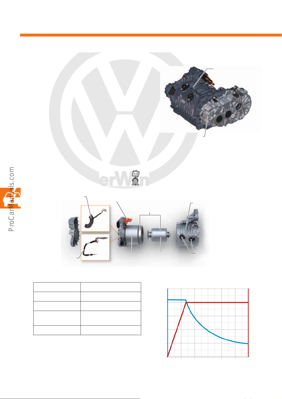
P
r
o
t
e
c
t
e
d
b
y
c
o
p
y
r
i
g
h
t
.
C
o
p
y
i
n
g
f
o
r
p
r
i
v
a
t
e
o
r
c
o
m
m
e
r
c
i
a
l
p
u
r
p
o
s
e
s
,
i
n
p
a
r
t
o
r
i
n
w
h
o
l
e
,
i
s
n
o
t
p
e
r
m
i
t
t
e
d
u
n
l
e
s
s
a
u
t
h
o
r
i
s
e
d
b
y
V
o
l
k
s
w
a
g
e
n
A
G
.
V
o
l
k
s
w
a
g
e
n
A
G
d
o
e
s
n
o
t
g
u
a
r
a
n
t
e
e
o
r
a
c
c
e
p
t
a
n
y
l
i
a
b
i
l
i
t
y
w
i
t
h
r
e
s
p
e
c
t
t
o
t
h
e
c
o
r
r
e
c
t
n
e
s
s
o
f
i
n
f
o
r
m
a
t
i
o
n
i
n
t
h
i
s
d
o
c
u
m
e
n
t
.
C
o
p
y
r
i
g
h
t
b
y
V
o
l
k
s
w
a
g
e
n
A
G
.
[Nm]
2000
[kW]
4000 6000 100008000
0
50
100
150
200
250
0
15
30
45
60
75
s527_035
[rpm]
High-voltage system
Three-phase current
drive VX54
s527_125
1-gear gearbox 0CZ
s527_037
Stator
Coolant connections
Electric drive motor V141
Motor housing
Drive motor
temperature sender
G712
Drive motor rotor position
sender 1 G713
Three phase
connections
Rotor
Three-phase current drive VX54
The three-phase current drive VX54 has a cast
aluminium housing and is paired as one component
together with the 1-gear gearbox 0CZ.
Design
The three-phase current drive VX54 contains the
electric drive motor V141, the drive motor
temperature sender G712, the drive motor rotor
position sender 1 G713, the coolant connections and
the three phase connections.
The stator consists of 5 coils per phase and the rotor
consists of 5 magnetic pole pairs. This results in good
response and a high degree of efficiency.
Technical data
Max. output 60kW
Max. torque 210Nm
Max. motor speed 12000rpm
Weight including
gearbox
Efficiency up to 94%
76kg
Torque and power diagram
30
Page 31
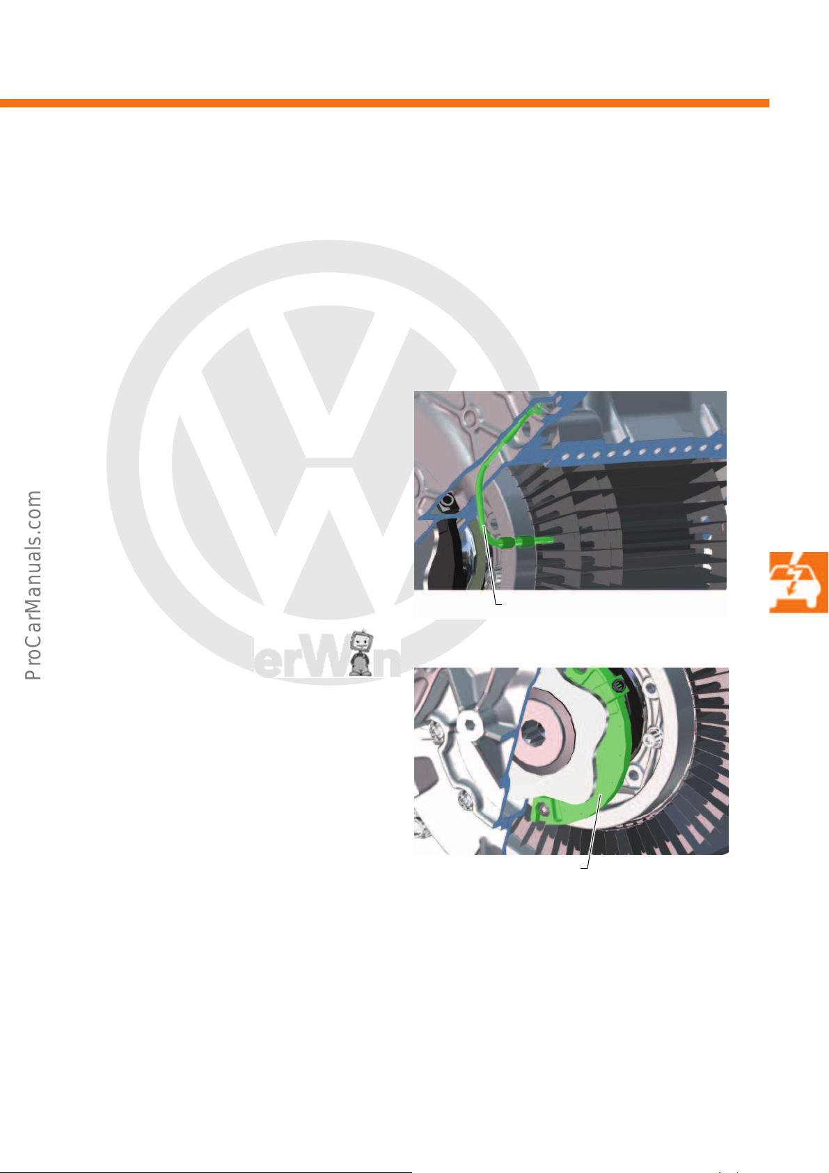
P
r
o
t
e
c
t
e
d
b
y
c
o
p
y
r
i
g
h
t
.
C
o
p
y
i
n
g
f
o
r
p
r
i
v
a
t
e
o
r
c
o
m
m
e
r
c
i
a
l
p
u
r
p
o
s
e
s
,
i
n
p
a
r
t
o
r
i
n
w
h
o
l
e
,
i
s
n
o
t
p
e
r
m
i
t
t
e
d
u
n
l
e
s
s
a
u
t
h
o
r
i
s
e
d
b
y
V
o
l
k
s
w
a
g
e
n
A
G
.
V
o
l
k
s
w
a
g
e
n
A
G
d
o
e
s
n
o
t
g
u
a
r
a
n
t
e
e
o
r
a
c
c
e
p
t
a
n
y
l
i
a
b
i
l
i
t
y
w
i
t
h
r
e
s
p
e
c
t
t
o
t
h
e
c
o
r
r
e
c
t
n
e
s
s
o
f
i
n
f
o
r
m
a
t
i
o
n
i
n
t
h
i
s
d
o
c
u
m
e
n
t
.
C
o
p
y
r
i
g
h
t
b
y
V
o
l
k
s
w
a
g
e
n
A
G
.
Electric drive motor V141
s527_041
Drive motor temperature
sender G712
s527_043
Drive motor rotor position
sender 1 G713
The electric drive motor V141 converts the three-phase current into drive power.
The internal rotor is weighted and two bearings keep it in position. If the electric drive motor V141 is not being
used as a drive motor, it takes on an alternator function.
Sensors
Drive motor temperature sender G712
The drive motor temperature sender G712 records
the temperature of the coils in the stator.
The NTC sensor (Negative Temperature Coefficient) is
directly connected to the power and control
electronics for electric drive JX1. With a core
temperature of 150 °C or more, the power is
restricted and shortly afterwards the electric drive
motor V141 is switched off.
Drive motor rotor position sender 1 G713
The drive motor rotor position sender 1 G713 is to the
right of the three-phase current drive VX54 and
works as an inductive sender with enhanced
evaluation. The sender wheel is driven by the rotor
and the fixed sensor records the position, the direction
of rotation and the component tolerances. It is directly
connected to the power and control electronics for
electric drive JX1.
Effects upon failure
In event of a sensor failure, the vehicle is no longer
operational for driving.
31
Page 32
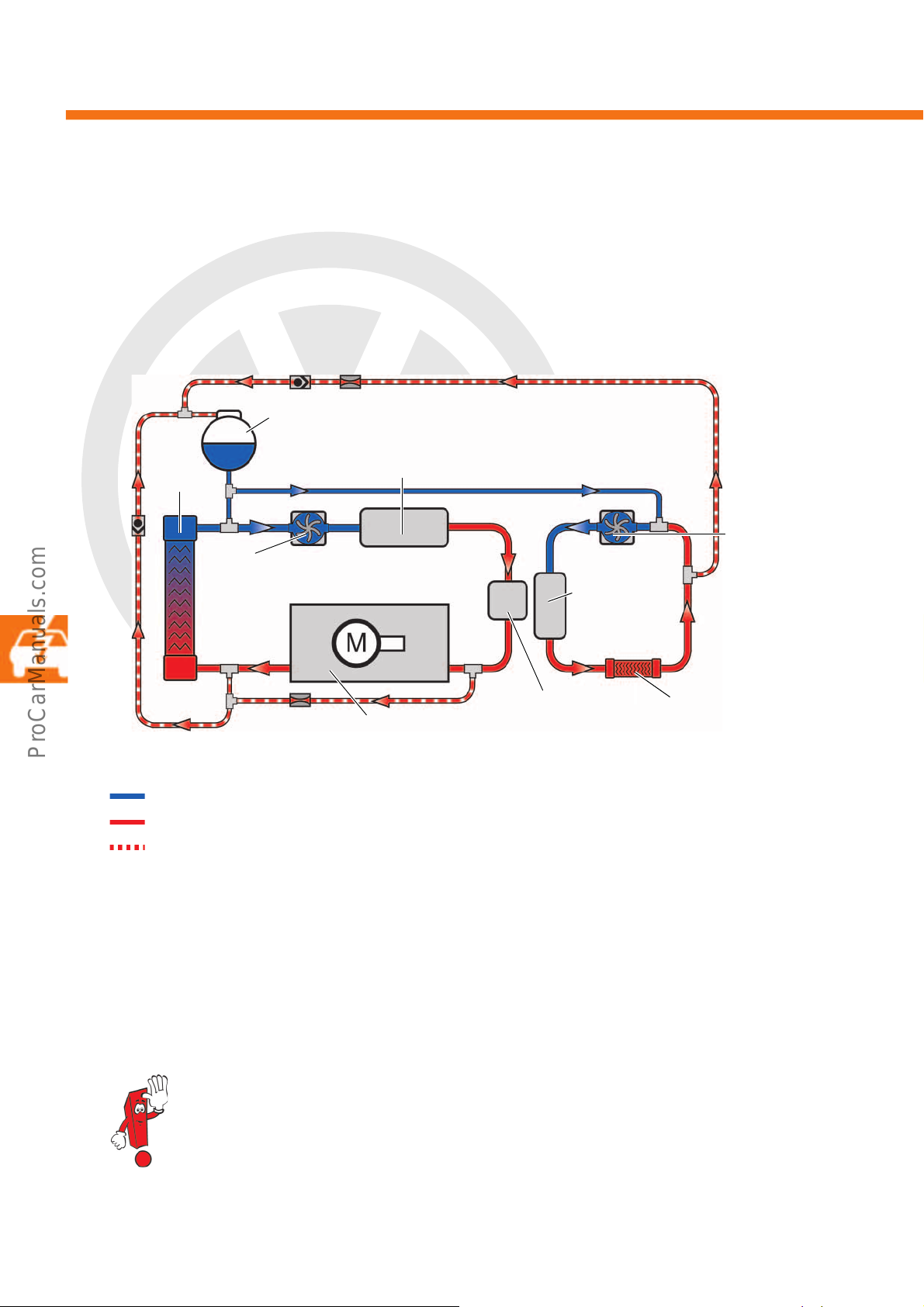
P
r
o
t
e
c
t
e
d
b
y
c
o
p
y
r
i
g
h
t
.
C
o
p
y
i
n
g
f
o
r
p
r
i
v
a
t
e
o
r
c
o
m
m
e
r
c
i
a
l
p
u
r
p
o
s
e
s
,
i
n
p
a
r
t
o
r
i
n
w
h
o
l
e
,
i
s
n
o
t
p
e
r
m
i
t
t
e
d
u
n
l
e
s
s
a
u
t
h
o
r
i
s
e
d
b
y
V
o
l
k
s
w
a
g
e
n
A
G
.
V
o
l
k
s
w
a
g
e
n
A
G
d
o
e
s
n
o
t
g
u
a
r
a
n
t
e
e
o
r
a
c
c
e
p
t
a
n
y
l
i
a
b
i
l
i
t
y
w
i
t
h
r
e
s
p
e
c
t
t
o
t
h
e
c
o
r
r
e
c
t
n
e
s
s
o
f
i
n
f
o
r
m
a
t
i
o
n
i
n
t
h
i
s
d
o
c
u
m
e
n
t
.
C
o
p
y
r
i
g
h
t
b
y
V
o
l
k
s
w
a
g
e
n
A
G
.
High-voltage system
Power and control electronics
Expansion tank
Coolant circulation pump
Coolant circulation
pump
High-voltage
heater (PTC)
Heat exchanger for heater
Three-phase current drive
s527_038
Charger
Radiator
Coolant
To protect them from high temperatures, all sensitive components are kept at the correct temperature using
coolant. The coolant has a temperature of up to 65°C and is electronically monitored and controlled by the engine
(motor) control unit J623. The following components are cooled with coolant:
• Three-phase current drive VX54
• Charging unit 1 for high-voltage battery AX4
• Power and control electronics for electric drive JX1
Key
32
Cold coolant
Warm coolant
Pressure equalisation coolant
Power and control electronics for electric drive JX1
The power and control electronics control the power flow from the high-voltage battery 1 AX2 to the three-phase
current drive VX54. It is installed at the front of the motor compartment on the right-hand side. It is also responsible
for charging the 12-volt onboard supply battery.
Further information can be found in the Self-study Programme no. 525, “The Jetta Hybrid”.
Page 33
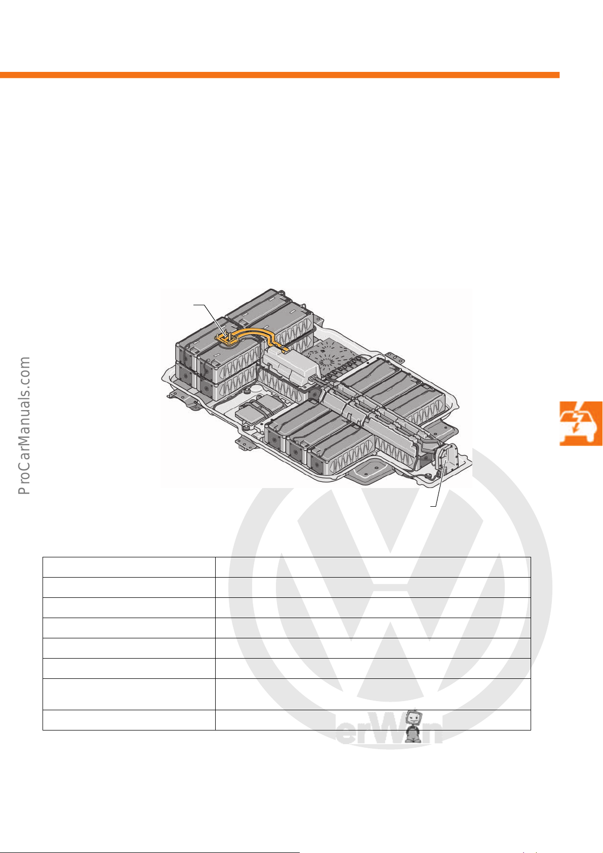
P
r
o
t
e
c
t
e
d
b
y
c
o
p
y
r
i
g
h
t
.
C
o
p
y
i
n
g
f
o
r
p
r
i
v
a
t
e
o
r
c
o
m
m
e
r
c
i
a
l
p
u
r
p
o
s
e
s
,
i
n
p
a
r
t
o
r
i
n
w
h
o
l
e
,
i
s
n
o
t
p
e
r
m
i
t
t
e
d
u
n
l
e
s
s
a
u
t
h
o
r
i
s
e
d
b
y
V
o
l
k
s
w
a
g
e
n
A
G
.
V
o
l
k
s
w
a
g
e
n
A
G
d
o
e
s
n
o
t
g
u
a
r
a
n
t
e
e
o
r
a
c
c
e
p
t
a
n
y
l
i
a
b
i
l
i
t
y
w
i
t
h
r
e
s
p
e
c
t
t
o
t
h
e
c
o
r
r
e
c
t
n
e
s
s
o
f
i
n
f
o
r
m
a
t
i
o
n
i
n
t
h
i
s
d
o
c
u
m
e
n
t
.
C
o
p
y
r
i
g
h
t
b
y
V
o
l
k
s
w
a
g
e
n
A
G
.
High-voltage battery 1 AX2
s527_040
High-voltage battery charging
connection 1 U34, optional DC
charging connection
Connection for converted DC current from the AC charging connection
The high-voltage battery is a lithium ion high-voltage battery. This is installed in the vehicle underbody. The
advantages of this are a low centre of gravity and optimised weight distibution.
The high-voltage battery 1 AX2 provides the energy for driving and is available in two versions:
• Series with AC charging connection
• With AC and DC charging connection (optional)
Technical data
Weight 230kg
Number of cells 204 cells, 2 x 10² battery cell pairs, connected in parallel
Cell type Lithium ion 3.75V; 25 Ah
Nominal voltage 374V
Capacity 50Ah
Nominal energy 18.7 kWh
Operating range –30 °C to +50 °C
Battery cell chemistry Lithium ion rechargeable battery with nickel, manganese and cobalt oxide
For differing temperatures the power is reduced or switched off completely.
33
Page 34
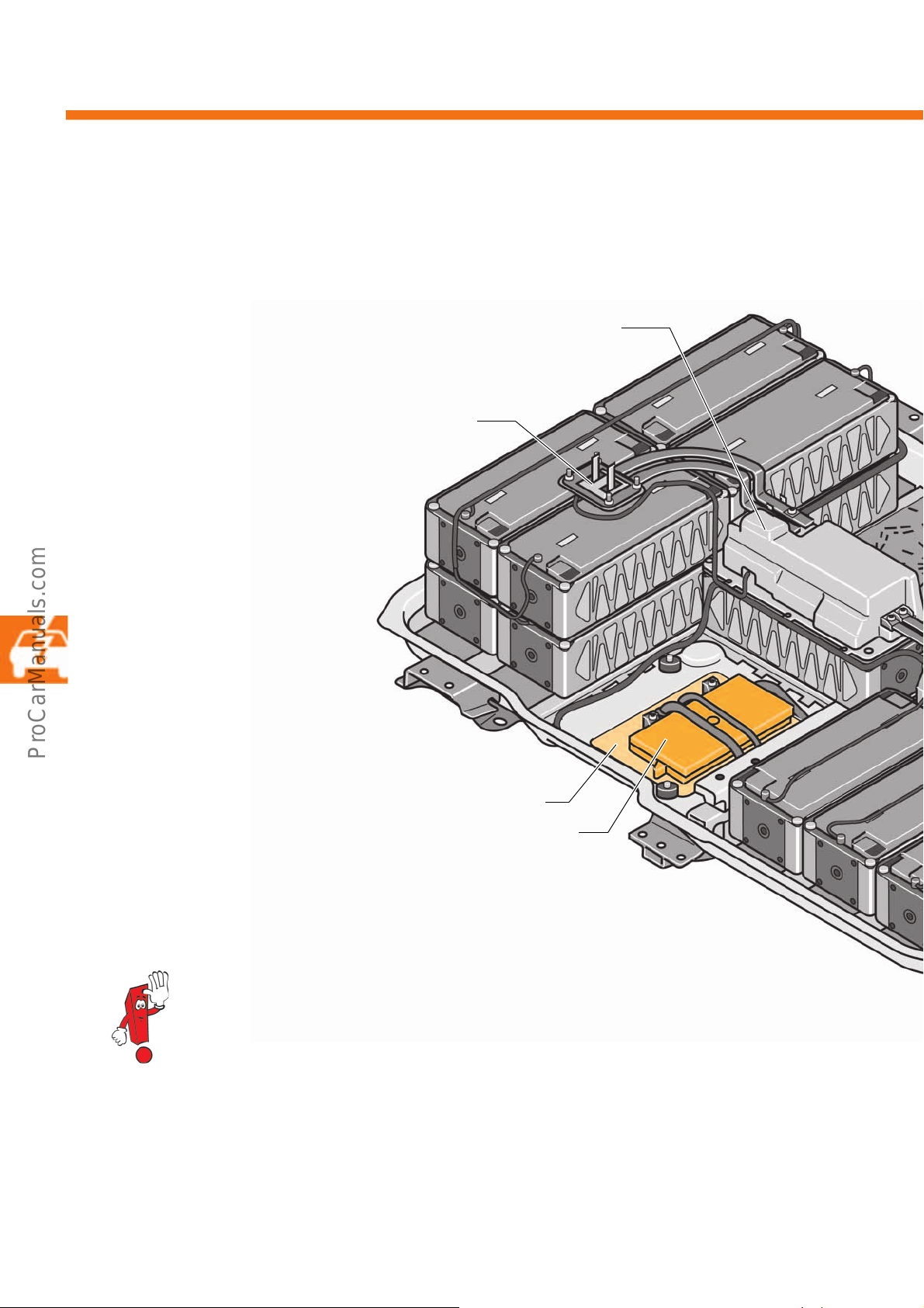
P
r
o
t
e
c
t
e
d
b
y
c
o
p
y
r
i
g
h
t
.
C
o
p
y
i
n
g
f
o
r
p
r
i
v
a
t
e
o
r
c
o
m
m
e
r
c
i
a
l
p
u
r
p
o
s
e
s
,
i
n
p
a
r
t
o
r
i
n
w
h
o
l
e
,
i
s
n
o
t
p
e
r
m
i
t
t
e
d
u
n
l
e
s
s
a
u
t
h
o
r
i
s
e
d
b
y
V
o
l
k
s
w
a
g
e
n
A
G
.
V
o
l
k
s
w
a
g
e
n
A
G
d
o
e
s
n
o
t
g
u
a
r
a
n
t
e
e
o
r
a
c
c
e
p
t
a
n
y
l
i
a
b
i
l
i
t
y
w
i
t
h
r
e
s
p
e
c
t
t
o
t
h
e
c
o
r
r
e
c
t
n
e
s
s
o
f
i
n
f
o
r
m
a
t
i
o
n
i
n
t
h
i
s
d
o
c
u
m
e
n
t
.
C
o
p
y
r
i
g
h
t
b
y
V
o
l
k
s
w
a
g
e
n
A
G
.
High-voltage system
High-voltage battery charging connection 1 U34,
optional DC charging connection
Battery regulation control unit J840
Switching unit for high-voltage battery SX6 with:
pre-charging contactor for high-voltage battery J1044
DC charge contactor 1 and 2 J1052 and J1053.
Service flap
Overview of components
The overview shows the components of the high-voltage battery 1 AX2. It is sealed with a waterproof seal and
cannot be accessed from the outside. The battery regulation control unit J840 can be accessed via a service flap.
34
The high-voltage battery has the protection ratings IP 6k7 and IP 6K9 (IP = Internal Protection):
• 6 = Complete protection against accidental contact, dust protection (dustproof)
• K = Special requirement in the automotive sector
• 7 = Protection against water if submerged
• 9 = Protection against water during high-pressure/steam cleaning
In addition:
• B = Finger protection against fingers with a diameter of >12mm and up to 80 mm length
Page 35
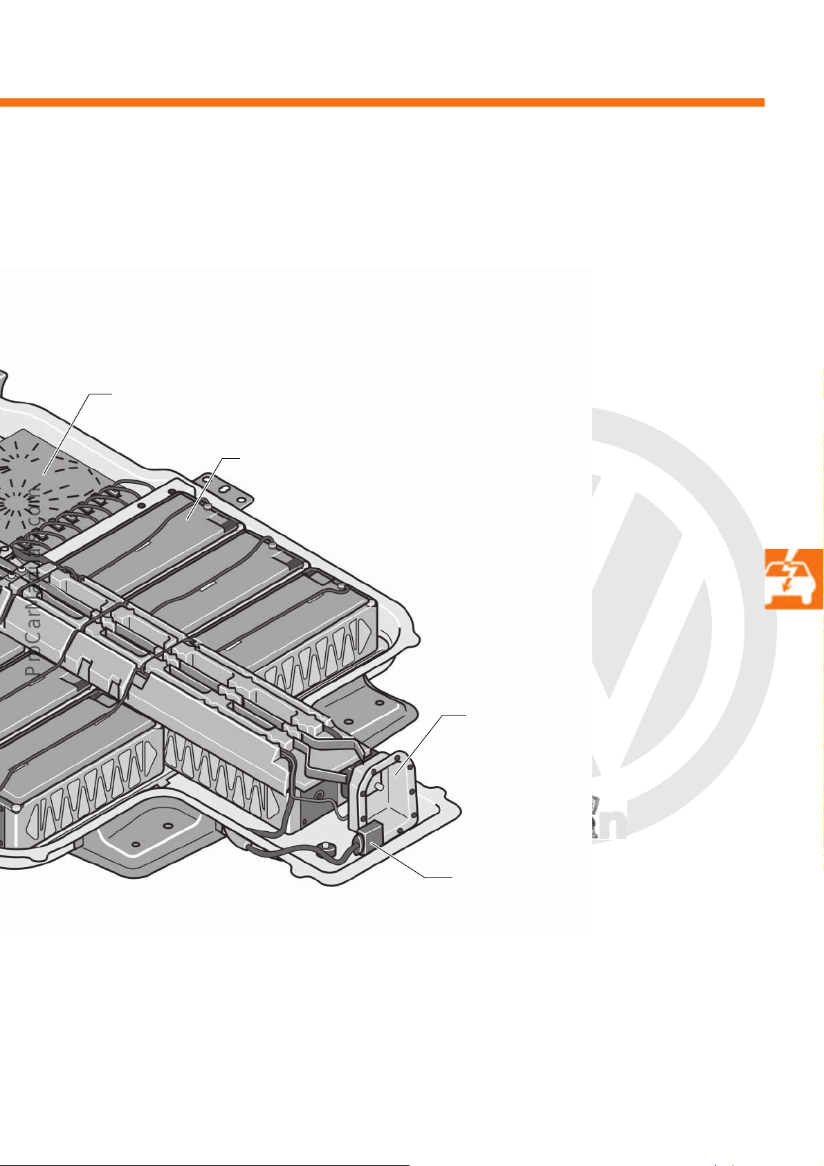
P
r
o
t
e
c
t
e
d
b
y
c
o
p
y
r
i
g
h
t
.
C
o
p
y
i
n
g
f
o
r
p
r
i
v
a
t
e
o
r
c
o
m
m
e
r
c
i
a
l
p
u
r
p
o
s
e
s
,
i
n
p
a
r
t
o
r
i
n
w
h
o
l
e
,
i
s
n
o
t
p
e
r
m
i
t
t
e
d
u
n
l
e
s
s
a
u
t
h
o
r
i
s
e
d
b
y
V
o
l
k
s
w
a
g
e
n
A
G
.
V
o
l
k
s
w
a
g
e
n
A
G
d
o
e
s
n
o
t
g
u
a
r
a
n
t
e
e
o
r
a
c
c
e
p
t
a
n
y
l
i
a
b
i
l
i
t
y
w
i
t
h
r
e
s
p
e
c
t
t
o
t
h
e
c
o
r
r
e
c
t
n
e
s
s
o
f
i
n
f
o
r
m
a
t
i
o
n
i
n
t
h
i
s
d
o
c
u
m
e
n
t
.
C
o
p
y
r
i
g
h
t
b
y
V
o
l
k
s
w
a
g
e
n
A
G
.
Module monitor control unit for batteries J497
Battery module 0 J1068 with NTC temperature sender,
each with 6 cells connected in parallel and 6 in series
High-voltage connection
12-volt connection to the onboard supply
s527_042
35
Page 36
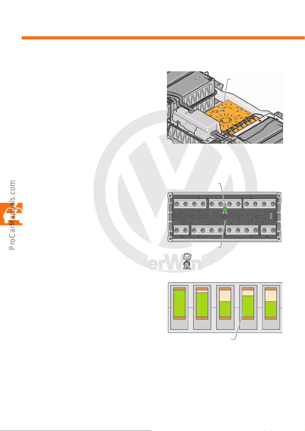
P
r
o
t
e
c
t
e
d
b
y
c
o
p
y
r
i
g
h
t
.
C
o
p
y
i
n
g
f
o
r
p
r
i
v
a
t
e
o
r
c
o
m
m
e
r
c
i
a
l
p
u
r
p
o
s
e
s
,
i
n
p
a
r
t
o
r
i
n
w
h
o
l
e
,
i
s
n
o
t
p
e
r
m
i
t
t
e
d
u
n
l
e
s
s
a
u
t
h
o
r
i
s
e
d
b
y
V
o
l
k
s
w
a
g
e
n
A
G
.
V
o
l
k
s
w
a
g
e
n
A
G
d
o
e
s
n
o
t
g
u
a
r
a
n
t
e
e
o
r
a
c
c
e
p
t
a
n
y
l
i
a
b
i
l
i
t
y
w
i
t
h
r
e
s
p
e
c
t
t
o
t
h
e
c
o
r
r
e
c
t
n
e
s
s
o
f
i
n
f
o
r
m
a
t
i
o
n
i
n
t
h
i
s
d
o
c
u
m
e
n
t
.
C
o
p
y
r
i
g
h
t
b
y
V
o
l
k
s
w
a
g
e
n
A
G
.
High-voltage system
s527_119
Module monitor control
unit for batteries J497
NTC temperature sender
s527_047
Battery module 0 J1068
100 %
1
90 %
50 %
70 %
50 %
Examples of possible tolerances
of the cell pairs among one
another
s527_110
2345
Module monitor control unit for batteries J497
The module monitor control unit for batteries J497 is
connected to each battery cell pair. It monitors the cell
voltage, the temperature (1x per battery module) and
the charge level. Controlling the charge level is
especially important to ensure that all cells have an
equal charge level. All information is sent to the
battery regulation control unit J840.
Temperature and voltage monitoring
To extend the service life of the cells, the voltage of
the battery cell pairs and the temperature of the 17
battery modules are monitored. Monitoring ensures
that the cells are kept within the optimum voltage and
temperature range, which in turn extends the service
life.
Charge level regulation
Charge level regulation ensures that all battery cells
have the same voltage level in order to achieve the
maximum battery capacity possible. The module
monitor control unit J497 measures the voltages and
discharges the fully charged cells via integrated
resistors. This ensures that all cells are equally
charged and the high-voltage battery uses maximum
capacity.
36
Page 37
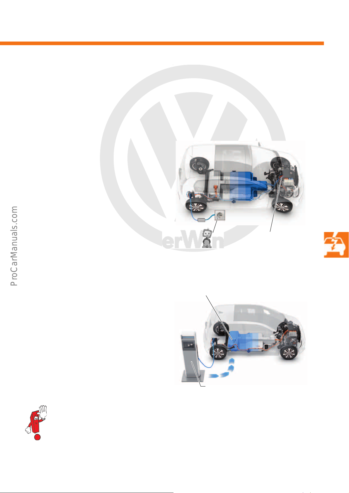
P
r
o
t
e
c
t
e
d
b
y
c
o
p
y
r
i
g
h
t
.
C
o
p
y
i
n
g
f
o
r
p
r
i
v
a
t
e
o
r
c
o
m
m
e
r
c
i
a
l
p
u
r
p
o
s
e
s
,
i
n
p
a
r
t
o
r
i
n
w
h
o
l
e
,
i
s
n
o
t
p
e
r
m
i
t
t
e
d
u
n
l
e
s
s
a
u
t
h
o
r
i
s
e
d
b
y
V
o
l
k
s
w
a
g
e
n
A
G
.
V
o
l
k
s
w
a
g
e
n
A
G
d
o
e
s
n
o
t
g
u
a
r
a
n
t
e
e
o
r
a
c
c
e
p
t
a
n
y
l
i
a
b
i
l
i
t
y
w
i
t
h
r
e
s
p
e
c
t
t
o
t
h
e
c
o
r
r
e
c
t
n
e
s
s
o
f
i
n
f
o
r
m
a
t
i
o
n
i
n
t
h
i
s
d
o
c
u
m
e
n
t
.
C
o
p
y
r
i
g
h
t
b
y
V
o
l
k
s
w
a
g
e
n
A
G
.
s527_055
High-voltage battery charging connection 1 U34,
optional DC charging connection
Charging with direct current
Charging with alternating
current
Charging unit 1 for
high-voltage battery
AX4
s527_053
Charging options for the high-voltage battery 1 AX2
The e-up! can be charged in two different ways: using alternating current (AC) or direct current (DC).
The high-voltage battery is always charged using direct current. Both alternating and direct current can be
connected to the vehicle.
Charging with alternating current (AC)
If alternating current is used to charge the highvoltage battery, the system uses the voltage converter
that is integrated into the vehicle, the charging unit 1
for high-voltage battery AX4. It is mounted at the
front of the drive compartment. The charger converts
the alternating current to direct current for charging.
The charger limits the charge power to a maximum of
3600 watts.
Charging with direct current (DC)
If direct current is used to charge the high-voltage
battery, it is directly supplied via the high-voltage
battery charging connection 1 U34.
The direct current is generated in the charging
equipment and has a maximum power of 50,000
watts.
The 12-volt onboard supply battery is charged when the high-voltage battery is charged.
37
Page 38
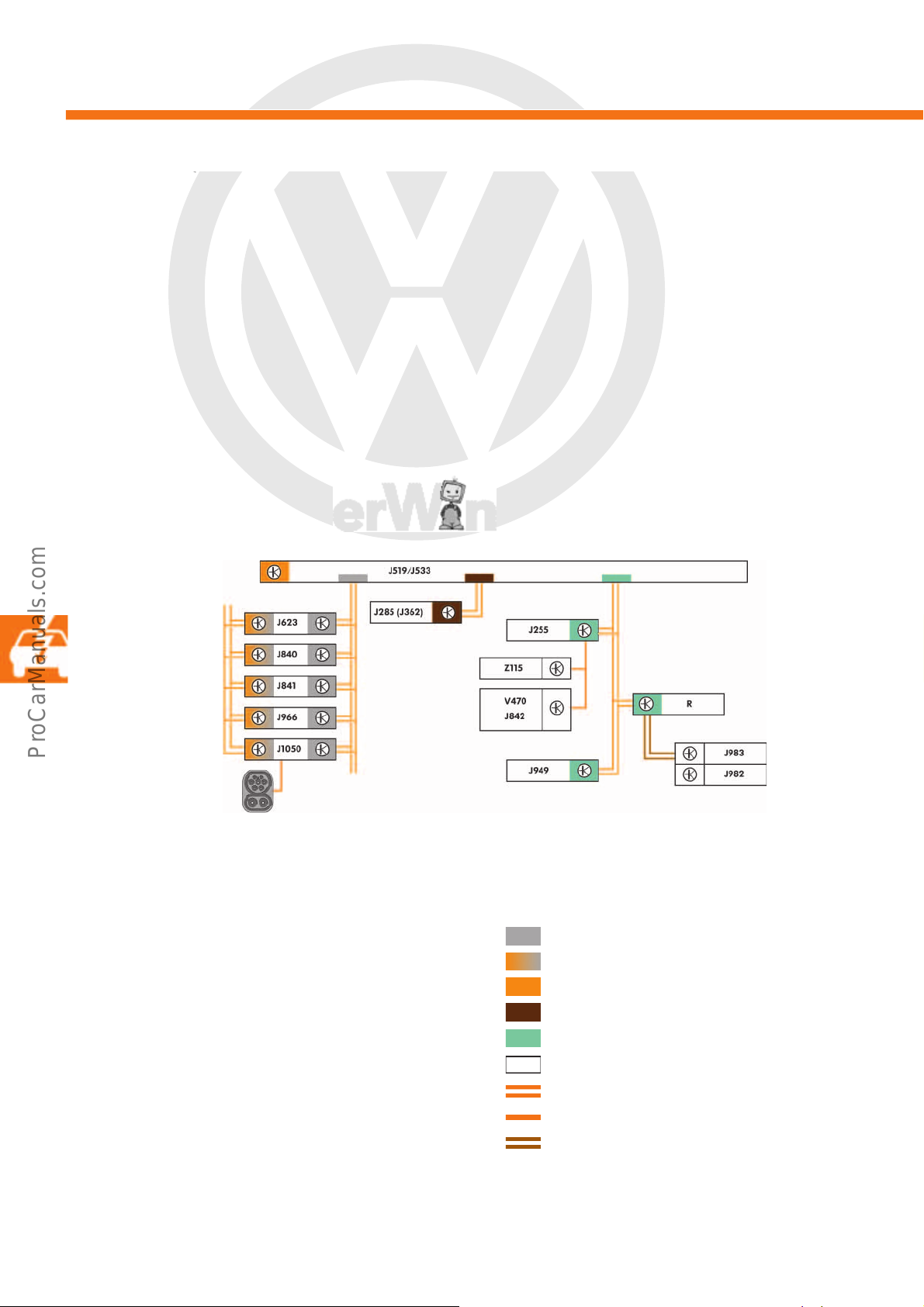
P
r
o
t
e
c
t
e
d
b
y
c
o
p
y
r
i
g
h
t
.
C
o
p
y
i
n
g
f
o
r
p
r
i
v
a
t
e
o
r
c
o
m
m
e
r
c
i
a
l
p
u
r
p
o
s
e
s
,
i
n
p
a
r
t
o
r
i
n
w
h
o
l
e
,
i
s
n
o
t
p
e
r
m
i
t
t
e
d
u
n
l
e
s
s
a
u
t
h
o
r
i
s
e
d
b
y
V
o
l
k
s
w
a
g
e
n
A
G
.
V
o
l
k
s
w
a
g
e
n
A
G
d
o
e
s
n
o
t
g
u
a
r
a
n
t
e
e
o
r
a
c
c
e
p
t
a
n
y
l
i
a
b
i
l
i
t
y
w
i
t
h
r
e
s
p
e
c
t
t
o
t
h
e
c
o
r
r
e
c
t
n
e
s
s
o
f
i
n
f
o
r
m
a
t
i
o
n
i
n
t
h
i
s
d
o
c
u
m
e
n
t
.
C
o
p
y
r
i
g
h
t
b
y
V
o
l
k
s
w
a
g
e
n
A
G
.
High-voltage system
s527_102
Charging plug
Charge control in the vehicle
Once the charging plug is plugged in, the charge
voltage control unit for high-voltage battery is active.
It triggers a lock on the charging plug and activates
the engine (motor) control unit. This ensures that all
high-voltage control units are ready for operation. As
long as there are no faults in any control units, the
high-voltage contactor controls are closed. The
engine (motor) control unit communicates to the
charge voltage control unit for high-voltage battery
that charging may take place. It monitors all highvoltage control units affected during charging. In the
event of a fault, charging is interrupted by the engine
(motor) control unit.
The onboard supply control unit is also activated. This
activates the following:
• Control unit in dash panel insert
• Emergency call module control unit and
communication unit
• Portable navigation and infotainment system
• Climatronic control unit
If all control units are active, the current charging
information can be displayed and called up. If the
charging plug is plugged in, the vehicle cannot be
made ready for driving.
Key
J255 Climatronic control unit
J285 Control unit in dash panel insert
J362 Immobiliser control unit
J519 Onboard supply control unit
J533 Data bus diagnostic interface
J623 Engine (motor) control unit
J840 Battery regulation control unit
J841 Electric drive control unit
J842 Control unit for air conditioning compressor
J949 Emergency call module control unit and
communication unit
J966 Charge voltage control unit for
high-voltage battery
J982 Portable navigation and infotainment system
J983 Interface for portable navigation
and infotainment system
J1050 Control unit for high-voltage battery charging unit
R Radio
V470 Electrical air conditioner compressor
Z115 High-voltage heater (PTC)
Powertrain CAN data bus
Hybrid CAN data bus
Diagnostic CAN data bus
Dash panel insert CAN data bus
Convenience CAN data bus
LIN data bus
CAN data bus wire
LIN data bus wire
Unidirectional LIN data bus wire
38
Page 39
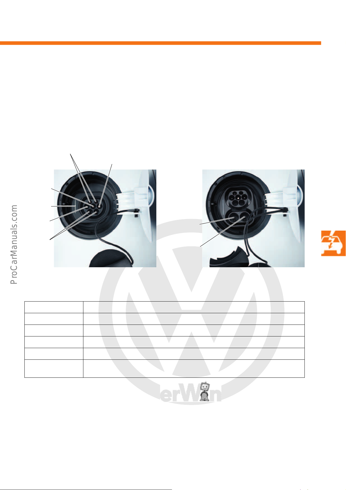
P
r
o
t
e
c
t
e
d
b
y
c
o
p
y
r
i
g
h
t
.
C
o
p
y
i
n
g
f
o
r
p
r
i
v
a
t
e
o
r
c
o
m
m
e
r
c
i
a
l
p
u
r
p
o
s
e
s
,
i
n
p
a
r
t
o
r
i
n
w
h
o
l
e
,
i
s
n
o
t
p
e
r
m
i
t
t
e
d
u
n
l
e
s
s
a
u
t
h
o
r
i
s
e
d
b
y
V
o
l
k
s
w
a
g
e
n
A
G
.
V
o
l
k
s
w
a
g
e
n
A
G
d
o
e
s
n
o
t
g
u
a
r
a
n
t
e
e
o
r
a
c
c
e
p
t
a
n
y
l
i
a
b
i
l
i
t
y
w
i
t
h
r
e
s
p
e
c
t
t
o
t
h
e
c
o
r
r
e
c
t
n
e
s
s
o
f
i
n
f
o
r
m
a
t
i
o
n
i
n
t
h
i
s
d
o
c
u
m
e
n
t
.
C
o
p
y
r
i
g
h
t
b
y
V
o
l
k
s
w
a
g
e
n
A
G
.
Charging connections
Control
LED
L1
PE
N
s527_061
Communication
Not
assigned
Direct current
–
s527_059
Direct current
+
The e-up! has different charging connections, depending on the model sold in a particular country. The European
versions are the simple AC charging connection or the double AC/DC charging connection. Both variants are
located behind the charging flap. For the Japanese market there is a self-contained variant in the motor
compartment.
AC charging connection
Connection Meaning
N Neutral wire
L1 Phase
PE Protective earth
Communication Creates a connection between the vehicle and the charging station.
Control LED The control LED can flash or light up in different colours. A detailed description of these can be
found on the next page.
AC/DC charging connection
39
Page 40
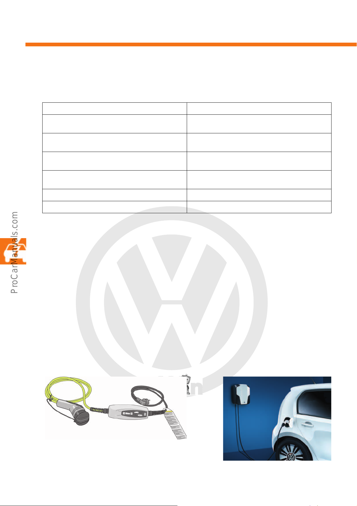
P
r
o
t
e
c
t
e
d
b
y
c
o
p
y
r
i
g
h
t
.
C
o
p
y
i
n
g
f
o
r
p
r
i
v
a
t
e
o
r
c
o
m
m
e
r
c
i
a
l
p
u
r
p
o
s
e
s
,
i
n
p
a
r
t
o
r
i
n
w
h
o
l
e
,
i
s
n
o
t
p
e
r
m
i
t
t
e
d
u
n
l
e
s
s
a
u
t
h
o
r
i
s
e
d
b
y
V
o
l
k
s
w
a
g
e
n
A
G
.
V
o
l
k
s
w
a
g
e
n
A
G
d
o
e
s
n
o
t
g
u
a
r
a
n
t
e
e
o
r
a
c
c
e
p
t
a
n
y
l
i
a
b
i
l
i
t
y
w
i
t
h
r
e
s
p
e
c
t
t
o
t
h
e
c
o
r
r
e
c
t
n
e
s
s
o
f
i
n
f
o
r
m
a
t
i
o
n
i
n
t
h
i
s
d
o
c
u
m
e
n
t
.
C
o
p
y
r
i
g
h
t
b
y
V
o
l
k
s
w
a
g
e
n
A
G
.
High-voltage system
s527_050
s527_063
Charging cable with charge control
Charging station for domestic installation
Control LED
The control LED for the relevant charging connection can flash or light up in different colours.
The following table gives a summary of all the LED modes.
LED Meaning
LED lights up red for up to 5 minutes (10 seconds after plugging in the charging plug)
LED lights up yellow for up to 5 minutes Plug recognised and locked but no supply voltage
LED flashes yellow for up to 5 minutes Selector lever is not in position P;
LED flashes green for 60 seconds at intervals of 4 seconds;
then the LED goes out
LED pulses green Charging process is active
LED lights up green for up to 5 minutes; then the LED goes out Charging process is complete
Charging options
Charge at home
A charging cable with charge control is delivered with the e-up! as standard. The charging cable fits every
standard plug socket. The charge power can be regulated and can be set between 1380, 1840 and 2300 watts.
The charging time is between 8 and 12 hours, depending on the setting. An integrated temperature sensor
monitors the temperature in the charging cable. If the temperature reaches 80 °C, the charge power is reduced.
If no drop in temperature occurs afterwards, the charging process is interrupted.
A charging station for domestic installation is available as an option in addition to the standard charging cable.
This is permanently installed by an expert and connected to the household power supply. The charge power is
3600 watts and the charging time approx. 6 hours.
Plug recognised but not locked;
charging is not possible
is available; charging is not possible
charging is not possible
Timer programming is activated;
waiting mode (not possible for DC charging)
40
Page 41
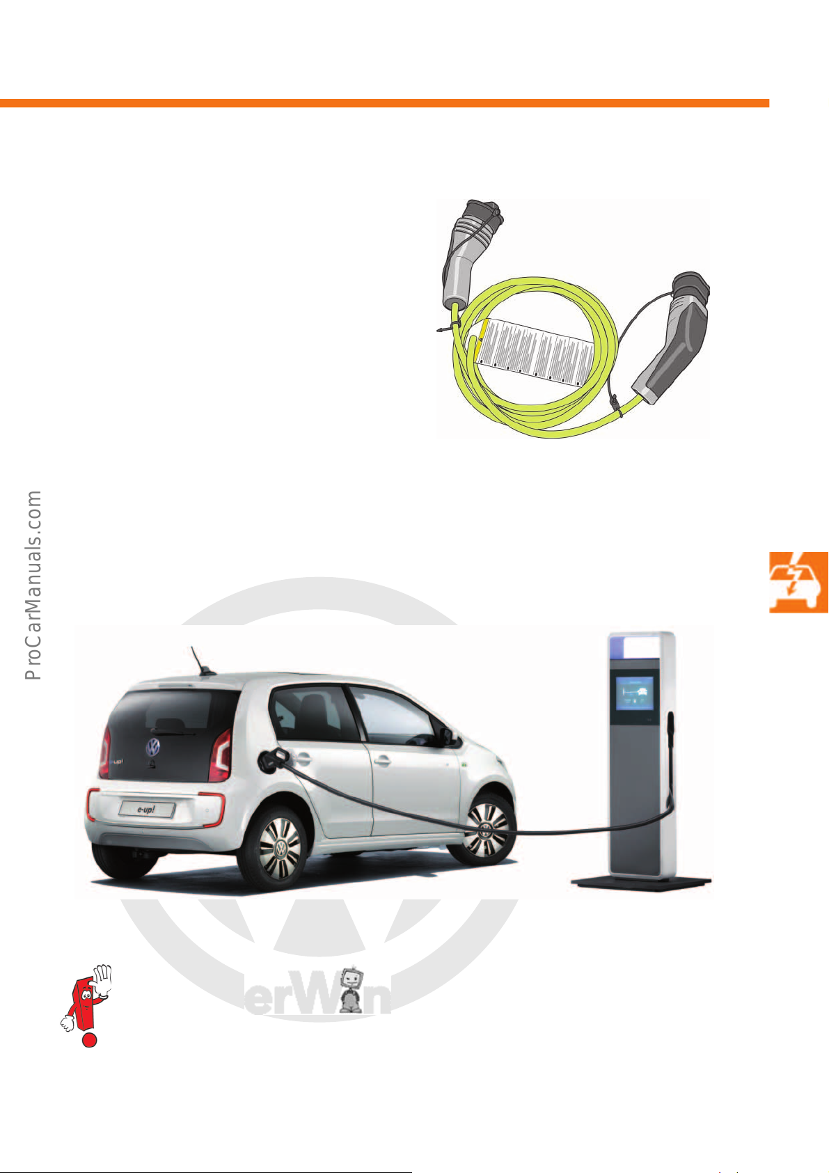
P
r
o
t
e
c
t
e
d
b
y
c
o
p
y
r
i
g
h
t
.
C
o
p
y
i
n
g
f
o
r
p
r
i
v
a
t
e
o
r
c
o
m
m
e
r
c
i
a
l
p
u
r
p
o
s
e
s
,
i
n
p
a
r
t
o
r
i
n
w
h
o
l
e
,
i
s
n
o
t
p
e
r
m
i
t
t
e
d
u
n
l
e
s
s
a
u
t
h
o
r
i
s
e
d
b
y
V
o
l
k
s
w
a
g
e
n
A
G
.
V
o
l
k
s
w
a
g
e
n
A
G
d
o
e
s
n
o
t
g
u
a
r
a
n
t
e
e
o
r
a
c
c
e
p
t
a
n
y
l
i
a
b
i
l
i
t
y
w
i
t
h
r
e
s
p
e
c
t
t
o
t
h
e
c
o
r
r
e
c
t
n
e
s
s
o
f
i
n
f
o
r
m
a
t
i
o
n
i
n
t
h
i
s
d
o
c
u
m
e
n
t
.
C
o
p
y
r
i
g
h
t
b
y
V
o
l
k
s
w
a
g
e
n
A
G
.
Charging while away from home
s527_052
Charging cable for AC charging stations
s527_111
Charging at a direct current charging station
A charging cable for public charging stations is also
available. The cable has a European standard plug,
which is often used at public charging stations. The
charge power is 3600 watts and the charging time
approx. 6 hours.
Another possibility is to charge using direct current at a quick charging station. These charging stations have a
power of up to 50,000 watts and charge the e-up! to 80 % within 30 minutes. Charging is then ended.
The aforementioned charging options may vary from country to country.
41
Page 42
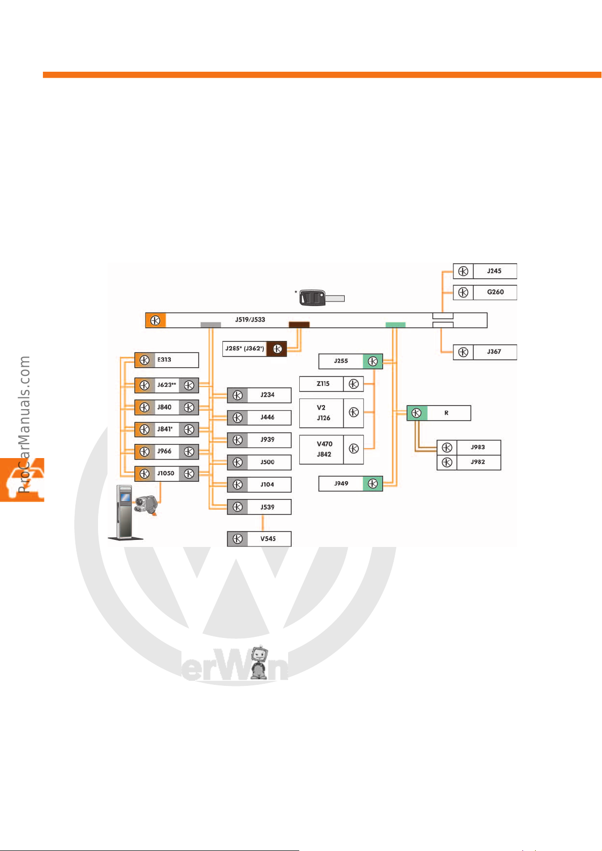
P
r
o
t
e
c
t
e
d
b
y
c
o
p
y
r
i
g
h
t
.
C
o
p
y
i
n
g
f
o
r
p
r
i
v
a
t
e
o
r
c
o
m
m
e
r
c
i
a
l
p
u
r
p
o
s
e
s
,
i
n
p
a
r
t
o
r
i
n
w
h
o
l
e
,
i
s
n
o
t
p
e
r
m
i
t
t
e
d
u
n
l
e
s
s
a
u
t
h
o
r
i
s
e
d
b
y
V
o
l
k
s
w
a
g
e
n
A
G
.
V
o
l
k
s
w
a
g
e
n
A
G
d
o
e
s
n
o
t
g
u
a
r
a
n
t
e
e
o
r
a
c
c
e
p
t
a
n
y
l
i
a
b
i
l
i
t
y
w
i
t
h
r
e
s
p
e
c
t
t
o
t
h
e
c
o
r
r
e
c
t
n
e
s
s
o
f
i
n
f
o
r
m
a
t
i
o
n
i
n
t
h
i
s
d
o
c
u
m
e
n
t
.
C
o
p
y
r
i
g
h
t
b
y
V
o
l
k
s
w
a
g
e
n
A
G
.
Electrical system
s527_056
External charging unit
(for DC charging only)
a
Vehicle electrical system
Due to the increased number of control units in the drive compartment, the hybrid CAN data bus is used as well as
the powertrain CAN bus. This is a sub-bus (without gateway connection) and is used for communication between
the individual high-voltage components.
Unlike the conventional up!, the dash panel insert is connected to the vehicle network via its own dash panel insert
CAN data bus.
Key
a Private CAN data bus
E313 Selector lever
G260 Humidity sender for air conditioning system
J104 ABS control unit
J126 Fresh air blower control unit
J234 Airbag control unit
J245 Sliding sunroof adjustment control unit
J255 Climatronic control unit
J285 Control unit in dash panel insert
J362 Immobiliser control unit
J367 Battery monitor control unit
J446 Parking aid control unit
J500 Power steering control unit
J519 Onboard supply control unit
42
J533 Data bus diagnostic interface
J539 Brake servo control unit
J623 Engine (motor) control unit
J840 Battery regulation control unit
J841 Electric drive control unit
J842 Control unit for air conditioning compressor
J939 Emergency braking function sensor unit
J949 Emergency call module control unit and
communication unit
J966 Charge voltage control unit for
high-voltage battery
J982 Portable navigation and infotainment system
J983 Interface for portable navigation
and infotainment system
Page 43
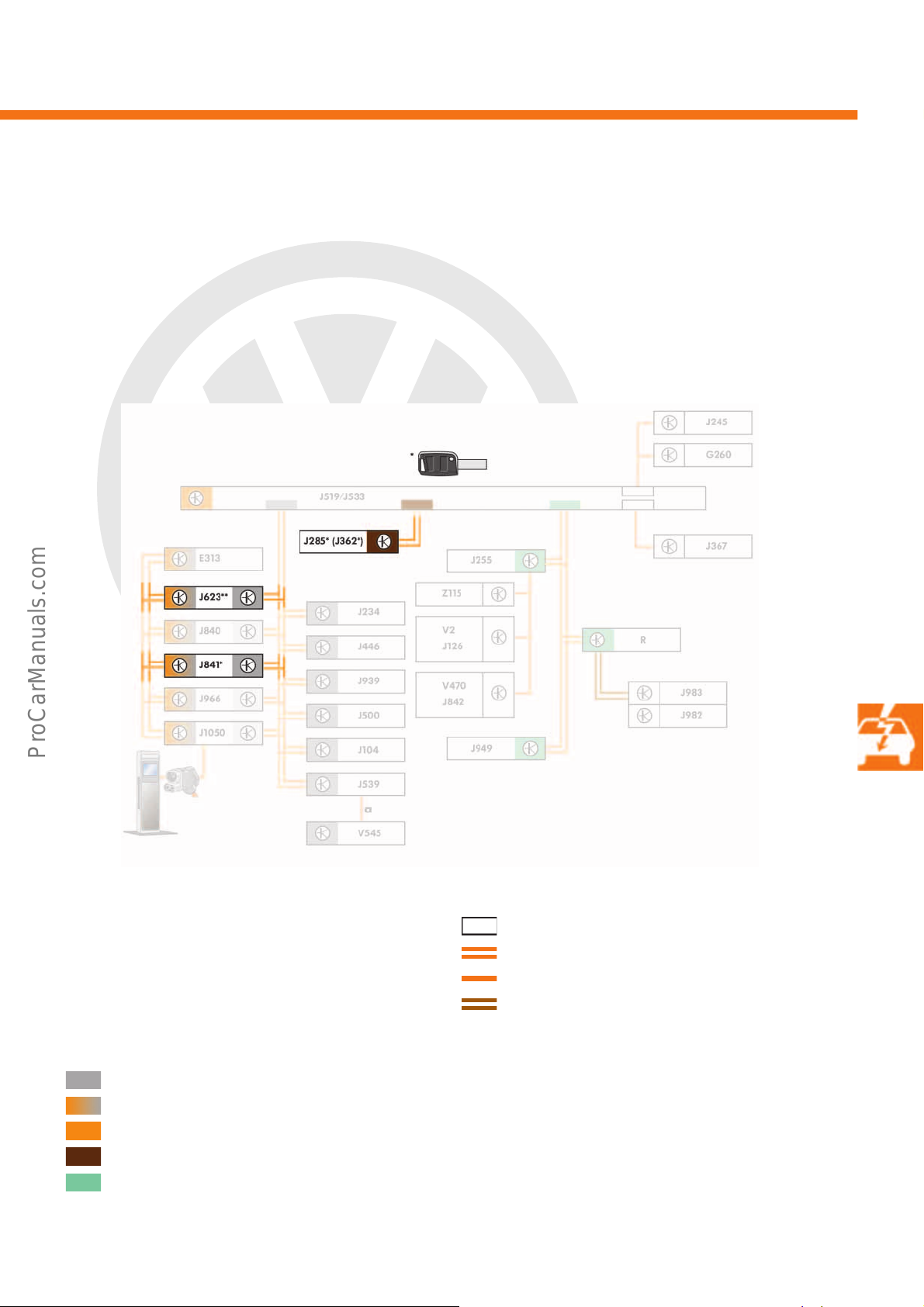
P
r
o
t
e
c
t
e
d
b
y
c
o
p
y
r
i
g
h
t
.
C
o
p
y
i
n
g
f
o
r
p
r
i
v
a
t
e
o
r
c
o
m
m
e
r
c
i
a
l
p
u
r
p
o
s
e
s
,
i
n
p
a
r
t
o
r
i
n
w
h
o
l
e
,
i
s
n
o
t
p
e
r
m
i
t
t
e
d
u
n
l
e
s
s
a
u
t
h
o
r
i
s
e
d
b
y
V
o
l
k
s
w
a
g
e
n
A
G
.
V
o
l
k
s
w
a
g
e
n
A
G
d
o
e
s
n
o
t
g
u
a
r
a
n
t
e
e
o
r
a
c
c
e
p
t
a
n
y
l
i
a
b
i
l
i
t
y
w
i
t
h
r
e
s
p
e
c
t
t
o
t
h
e
c
o
r
r
e
c
t
n
e
s
s
o
f
i
n
f
o
r
m
a
t
i
o
n
i
n
t
h
i
s
d
o
c
u
m
e
n
t
.
C
o
p
y
r
i
g
h
t
b
y
V
o
l
k
s
w
a
g
e
n
A
G
.
Immobiliser
s527_058
To increase the level of theft protection of the e-up!, some individual immobiliser components have already been
upgraded from generation IVc to generation V. The immobiliser control unit J362, which is integrated into the
control unit for the dash panel insert J285, is the master. It can operate immobiliser slaves of immobiliser
generations IVc and V; it works according to the principle of immobilizer IVc. The engine (motor) control unit J623
is therefore a generation V immobiliser slave. The electric drive control unit J841 is a generation IVc immobiliser
slave.
J1050 Control unit for high-voltage battery charging unit
V2 Fresh air blower
V470 Electrical air conditioner compressor
V545 Motor in brake pressure accumulator for energy
recovery
RRadio
Z115 High-voltage heater (PTC)
Powertrain CAN data bus
Hybrid CAN data bus
Diagnostic CAN data bus
Dash panel insert CAN data bus
Convenience CAN data bus
LIN data bus
CAN data bus wire
LIN data bus wire
Unidirectional LIN data bus wire
* Immobiliser generation IVc
** Immobiliser generation V
43
Page 44
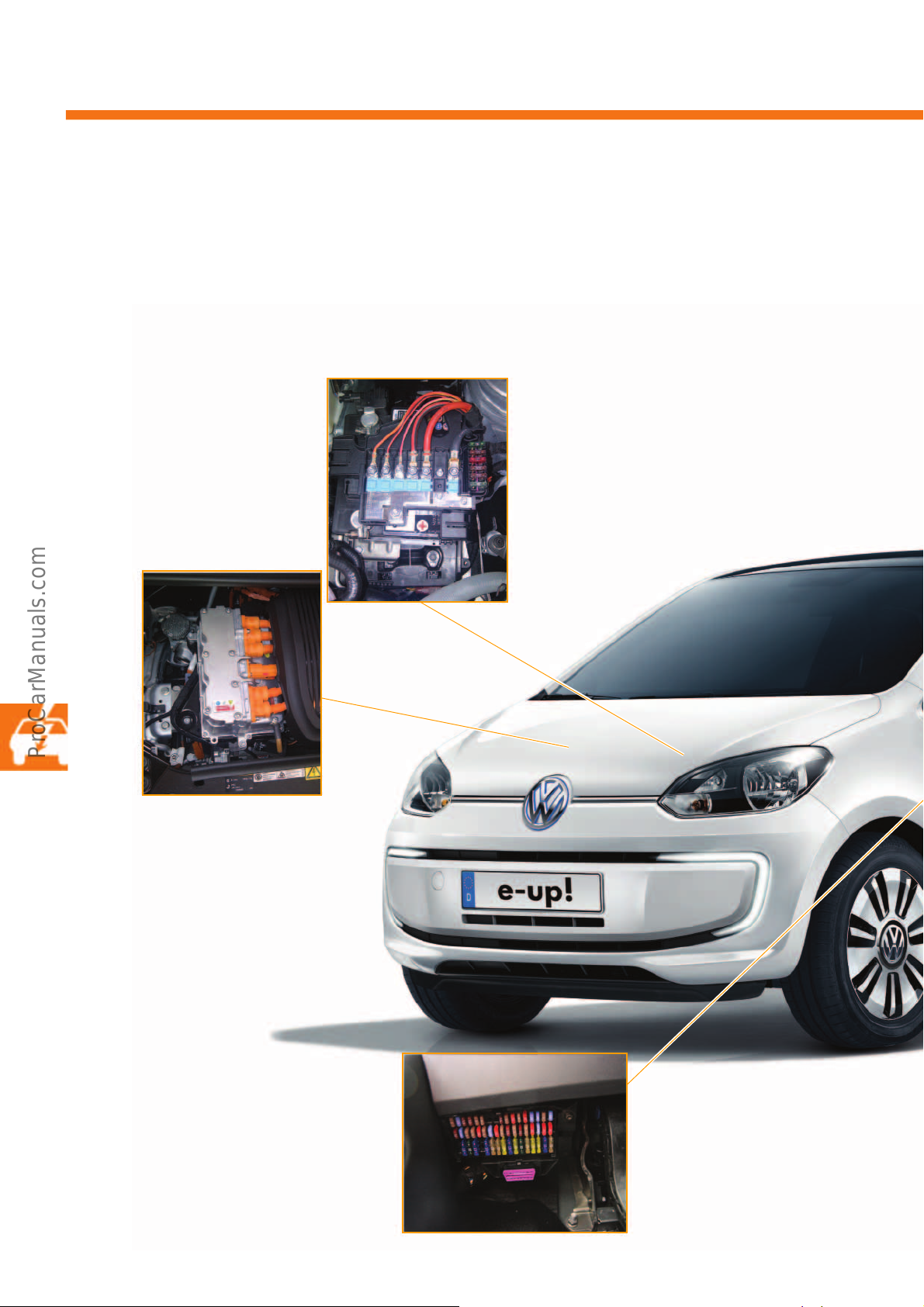
P
r
o
t
e
c
t
e
d
b
y
c
o
p
y
r
i
g
h
t
.
C
o
p
y
i
n
g
f
o
r
p
r
i
v
a
t
e
o
r
c
o
m
m
e
r
c
i
a
l
p
u
r
p
o
s
e
s
,
i
n
p
a
r
t
o
r
i
n
w
h
o
l
e
,
i
s
n
o
t
p
e
r
m
i
t
t
e
d
u
n
l
e
s
s
a
u
t
h
o
r
i
s
e
d
b
y
V
o
l
k
s
w
a
g
e
n
A
G
.
V
o
l
k
s
w
a
g
e
n
A
G
d
o
e
s
n
o
t
g
u
a
r
a
n
t
e
e
o
r
a
c
c
e
p
t
a
n
y
l
i
a
b
i
l
i
t
y
w
i
t
h
r
e
s
p
e
c
t
t
o
t
h
e
c
o
r
r
e
c
t
n
e
s
s
o
f
i
n
f
o
r
m
a
t
i
o
n
i
n
t
h
i
s
d
o
c
u
m
e
n
t
.
C
o
p
y
r
i
g
h
t
b
y
V
o
l
k
s
w
a
g
e
n
A
G
.
Electrical system
Installation points in the vehicle electrical system
Despite the electrification of the drive of the e-up! and the integrated high-voltage network, the power supply for
almost all convenience components is via a normal 12-volt onboard supply (except for the voltage supply).
• Fuse carrier on the vehicle battery with
additional fuse carrier
44
• In the e-up!, the power and
control electronics for electric
drive JX1 take care of the
supply, support and charging
for the 12-volt onboard
supply, instead of a
alternator as used in normal
combustion mode.
• Fuse box,
at the bottom left on the driver's
side of the passenger
compartment
Page 45
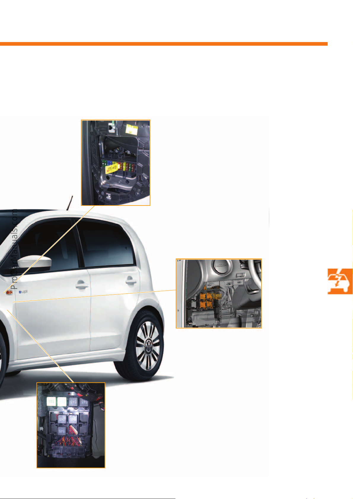
P
r
o
t
e
c
t
e
d
b
y
c
o
p
y
r
i
g
h
t
.
C
o
p
y
i
n
g
f
o
r
p
r
i
v
a
t
e
o
r
c
o
m
m
e
r
c
i
a
l
p
u
r
p
o
s
e
s
,
i
n
p
a
r
t
o
r
i
n
w
h
o
l
e
,
i
s
n
o
t
p
e
r
m
i
t
t
e
d
u
n
l
e
s
s
a
u
t
h
o
r
i
s
e
d
b
y
V
o
l
k
s
w
a
g
e
n
A
G
.
V
o
l
k
s
w
a
g
e
n
A
G
d
o
e
s
n
o
t
g
u
a
r
a
n
t
e
e
o
r
a
c
c
e
p
t
a
n
y
l
i
a
b
i
l
i
t
y
w
i
t
h
r
e
s
p
e
c
t
t
o
t
h
e
c
o
r
r
e
c
t
n
e
s
s
o
f
i
n
f
o
r
m
a
t
i
o
n
i
n
t
h
i
s
d
o
c
u
m
e
n
t
.
C
o
p
y
r
i
g
h
t
b
y
V
o
l
k
s
w
a
g
e
n
A
G
.
s527_065
• Fuse carrier, on the driver's side of the passenger
compartment, behind the left-hand dash panel.
The 10 A fuse marked with a tag interrupts the
power supply to the terminal 30c and therefore to
the battery regulation control unit J840 in the
event of an accident.
• Relay carrier,
on the driver's side of the
passenger compartment,
behind the left-hand dash
panel
• Onboard supply control unit J519 with an
integrated diagnostics interface for data
bus J533, behind the relay carrier
45
Page 46
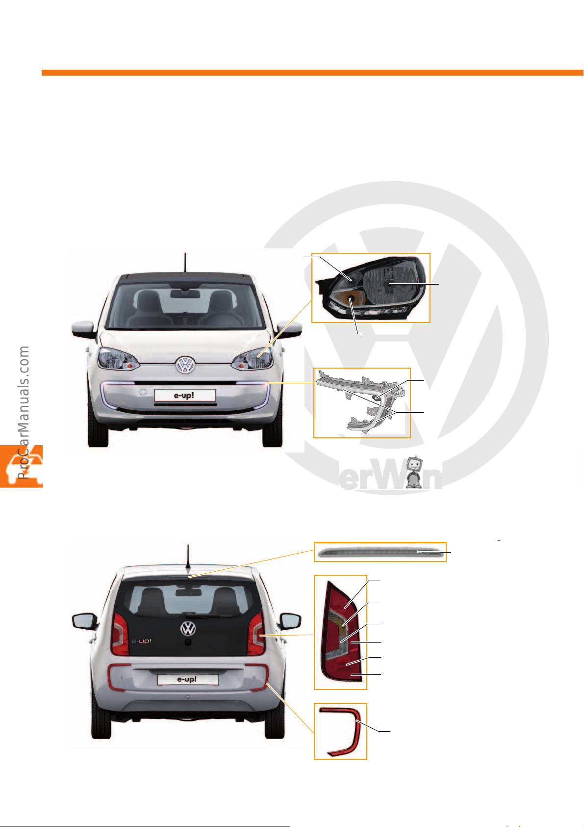
P
r
o
t
e
c
t
e
d
b
y
c
o
p
y
r
i
g
h
t
.
C
o
p
y
i
n
g
f
o
r
p
r
i
v
a
t
e
o
r
c
o
m
m
e
r
c
i
a
l
p
u
r
p
o
s
e
s
,
i
n
p
a
r
t
o
r
i
n
w
h
o
l
e
,
i
s
n
o
t
p
e
r
m
i
t
t
e
d
u
n
l
e
s
s
a
u
t
h
o
r
i
s
e
d
b
y
V
o
l
k
s
w
a
g
e
n
A
G
.
V
o
l
k
s
w
a
g
e
n
A
G
d
o
e
s
n
o
t
g
u
a
r
a
n
t
e
e
o
r
a
c
c
e
p
t
a
n
y
l
i
a
b
i
l
i
t
y
w
i
t
h
r
e
s
p
e
c
t
t
o
t
h
e
c
o
r
r
e
c
t
n
e
s
s
o
f
i
n
f
o
r
m
a
t
i
o
n
i
n
t
h
i
s
d
o
c
u
m
e
n
t
.
C
o
p
y
r
i
g
h
t
b
y
V
o
l
k
s
w
a
g
e
n
A
G
.
Electrical system
Side light (W21*/5W)
Dipped beam and main
beam (H4, 55/60 W)
Turn signal lights (PY, 21 W)
Light guide
s527_069
s527_071
Control unit for LED daytime
running light
(3 x 3 W, LUY H9QP)
s527_067
Tail light and rear fog lamp (P21, 4 W)
Tail light (P21*/4 W)
Tail light and brake light (P21, 4 W)
Turn signal light (R, 10W)
Reversing light (R, 10 W)
Reflector
g
white finish
(16 red LEDs)
Reflector
s527_123
* The 21watt glow coil is not triggered in the e-up!.
s527_073
s527_075
s527_077
The lighting system
The daytime running lights and the additional brake light have been adapted for the design concept of the e-up!.
Front lights
The front headlights of the e-up! do not differ in appearance from those of the up!. The difference is that the e-up!
uses two curved LED lights in the bumper as daytime running lights. The LED daytime running lights are switched
off when the dipped beam is switched off.
Rear lights
The rear lights on the e-up! are exactly the same as those of the up!. On the e-up!, the high-level brake lights have
a white lens with the red LEDs underneath.
46
Page 47
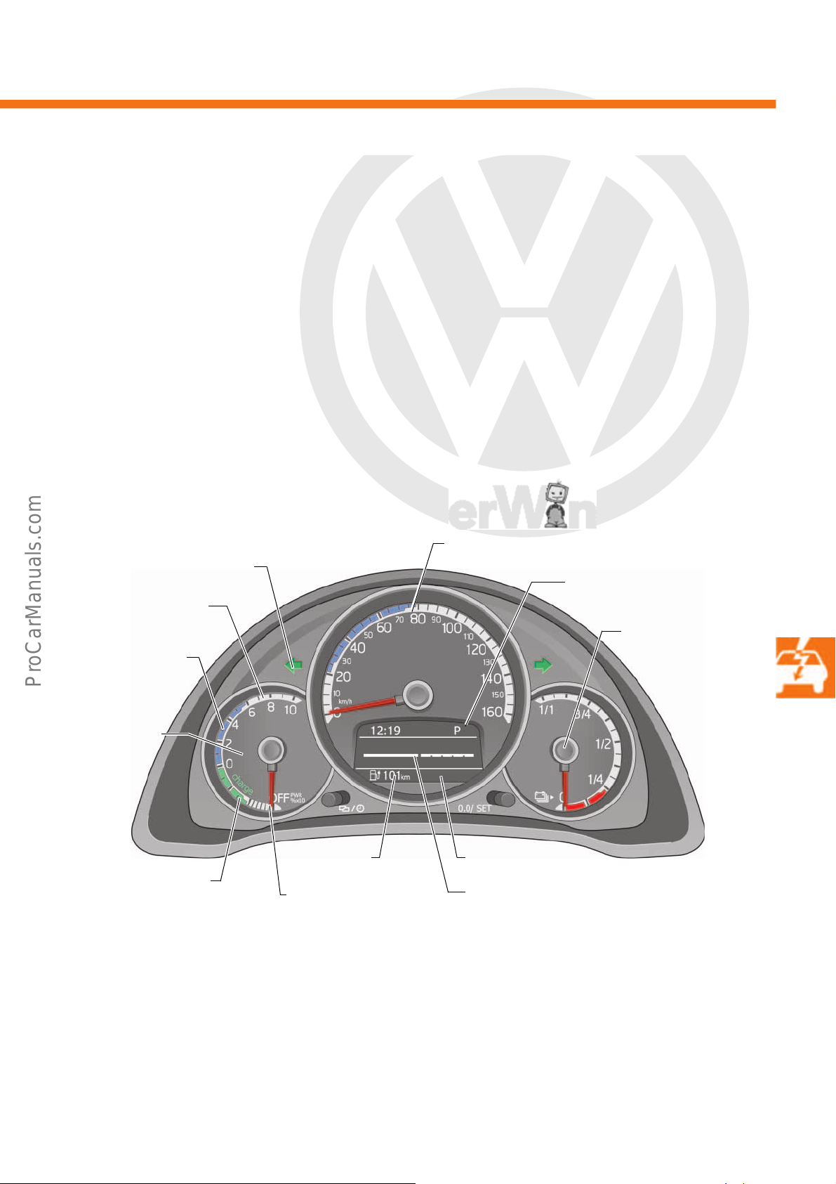
P
r
o
t
e
c
t
e
d
b
y
c
o
p
y
r
i
g
h
t
.
C
o
p
y
i
n
g
f
o
r
p
r
i
v
a
t
e
o
r
c
o
m
m
e
r
c
i
a
l
p
u
r
p
o
s
e
s
,
i
n
p
a
r
t
o
r
i
n
w
h
o
l
e
,
i
s
n
o
t
p
e
r
m
i
t
t
e
d
u
n
l
e
s
s
a
u
t
h
o
r
i
s
e
d
b
y
V
o
l
k
s
w
a
g
e
n
A
G
.
V
o
l
k
s
w
a
g
e
n
A
G
d
o
e
s
n
o
t
g
u
a
r
a
n
t
e
e
o
r
a
c
c
e
p
t
a
n
y
l
i
a
b
i
l
i
t
y
w
i
t
h
r
e
s
p
e
c
t
t
o
t
h
e
c
o
r
r
e
c
t
n
e
s
s
o
f
i
n
f
o
r
m
a
t
i
o
n
i
n
t
h
i
s
d
o
c
u
m
e
n
t
.
C
o
p
y
r
i
g
h
t
b
y
V
o
l
k
s
w
a
g
e
n
A
G
.
s527_060
Available power
Percentage
performance
indication
(power meter)
Turn signal warning lamp
Multifunction display (MFI)
Battery charge state
Energy recovery range
(green section)
Eco-friendly driving
(blue section)
Not ready to drive,
needle position
Readiness to drive
Available power
Remaining
range
Speed display
Normal driving
(white section)
Normal
E-Max
READY
Dash panel insert
The dash panel insert in the e-up! is based on the highline dash panel insert of the VW Beetle. For the e-up!, the
display instruments and the multifunction display (MFI) have been subjected to electric drive-specific modifications.
Next to the centrally positioned analogue speed display, the battery charge level and the percentage performance
indication (power meter) are shown on an analogue display.
The modified multifunction display (MFI) can display the following additional information:
•Battery range
• Momentary electrical consumption
• Average electrical consumption
• Information on the charging process
• Driving mode selection
• Ready to drive with the display “READY”
• Available power ( electrical power currently available)
47
Page 48
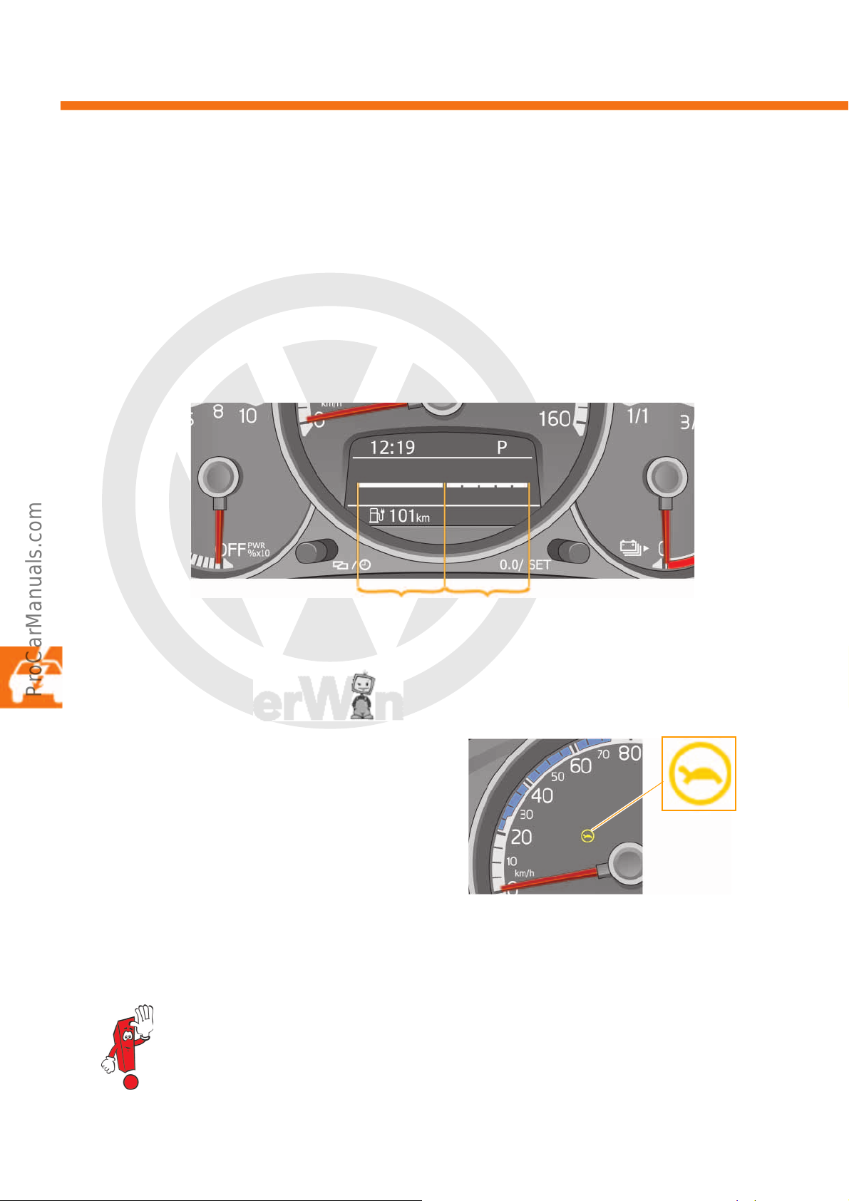
P
r
o
t
e
c
t
e
d
b
y
c
o
p
y
r
i
g
h
t
.
C
o
p
y
i
n
g
f
o
r
p
r
i
v
a
t
e
o
r
c
o
m
m
e
r
c
i
a
l
p
u
r
p
o
s
e
s
,
i
n
p
a
r
t
o
r
i
n
w
h
o
l
e
,
i
s
n
o
t
p
e
r
m
i
t
t
e
d
u
n
l
e
s
s
a
u
t
h
o
r
i
s
e
d
b
y
V
o
l
k
s
w
a
g
e
n
A
G
.
V
o
l
k
s
w
a
g
e
n
A
G
d
o
e
s
n
o
t
g
u
a
r
a
n
t
e
e
o
r
a
c
c
e
p
t
a
n
y
l
i
a
b
i
l
i
t
y
w
i
t
h
r
e
s
p
e
c
t
t
o
t
h
e
c
o
r
r
e
c
t
n
e
s
s
o
f
i
n
f
o
r
m
a
t
i
o
n
i
n
t
h
i
s
d
o
c
u
m
e
n
t
.
C
o
p
y
r
i
g
h
t
b
y
V
o
l
k
s
w
a
g
e
n
A
G
.
Electrical system
Available power
E-MaxNormal
s527_106
Normal E-Max
READY
s527_104
Available power
The power availability display shows the user whether the full power of 60 kW is available.
The power availability is shown using a progress bar. In the “E-Max” range, the maximum power is available to the
user for 30 seconds. As the power availability decreases, the five segments in the “E-Max” range gradually fade
out from right to left. If all the segments in the range have disappeared, the maximum power is no longer available
and the drive power is reduced. Reasons for the reduction in power are the increased system temperature and
maximisation of the battery range. If the system is too cold, the power is restricted. If the user only has a few more
kilometres of range remaining, the system is restricted to up to 15 kW to ensure it's still possible to drive a few more
kilometres.
Warning lamp for restricted maximum
speed K305
If the charge level of the high-voltage battery is in the
lower reserve range, the maximum possible driving
speed is reduced along with the power availability. If
the reserve of the high-voltage battery is reached, a
tortoise becomes visible in the dash panel insert, as
well as text notifications. The tortoise indicates that
the maximum driving speed has been restricted to 80
km/h. If the vehicle is not recharged, both the power
and the maximum speed will be gradually restricted
further.
48
If the vehicle comes to a standstill due to falling below the source voltage for a high-voltage battery, it
is possible to restart the e-up! twice for a limited distance: the first time for approx. 100 m and the
second time for approx. 50 m.
Page 49
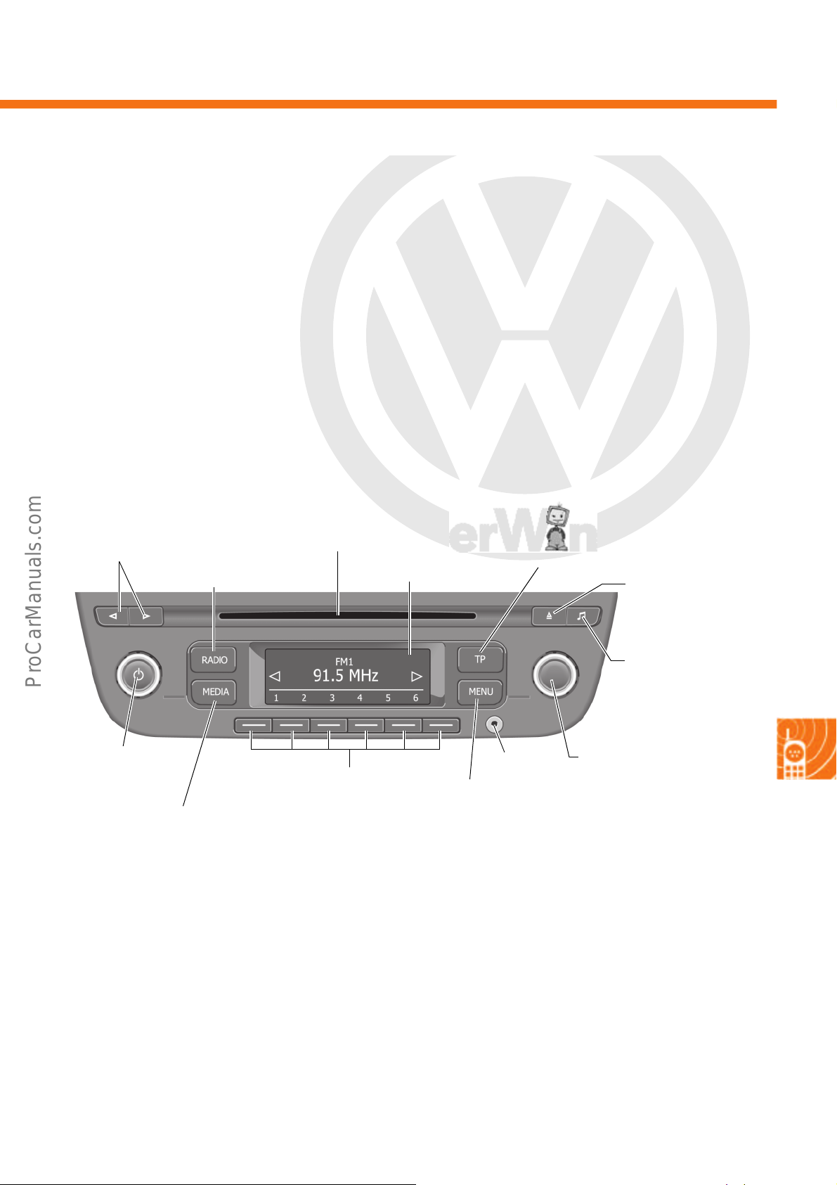
P
r
o
t
e
c
t
e
d
b
y
c
o
p
y
r
i
g
h
t
.
C
o
p
y
i
n
g
f
o
r
p
r
i
v
a
t
e
o
r
c
o
m
m
e
r
c
i
a
l
p
u
r
p
o
s
e
s
,
i
n
p
a
r
t
o
r
i
n
w
h
o
l
e
,
i
s
n
o
t
p
e
r
m
i
t
t
e
d
u
n
l
e
s
s
a
u
t
h
o
r
i
s
e
d
b
y
V
o
l
k
s
w
a
g
e
n
A
G
.
V
o
l
k
s
w
a
g
e
n
A
G
d
o
e
s
n
o
t
g
u
a
r
a
n
t
e
e
o
r
a
c
c
e
p
t
a
n
y
l
i
a
b
i
l
i
t
y
w
i
t
h
r
e
s
p
e
c
t
t
o
t
h
e
c
o
r
r
e
c
t
n
e
s
s
o
f
i
n
f
o
r
m
a
t
i
o
n
i
n
t
h
i
s
d
o
c
u
m
e
n
t
.
C
o
p
y
r
i
g
h
t
b
y
V
o
l
k
s
w
a
g
e
n
A
G
.
Infotainment
s527_062
AUX-IN
Rotary knob with push
button: on/off switch,
volume adjustment
Skip stations and
CD titles
Display
TP (Traffic Program) button:
traffic information function
CD slot
Sound settings
button
CD eject button
Rotary knob with push
button: menu settings,
manual station settings,
SCAN function
Display of additional
functions, calls up
setup
Function buttons: depending on the
menu
Radio operation button
Media operation button
RCD 215 radio
The RCD 215 radio already installed in the up! has been upgraded for the e-up! to include a function for DAB+
(Digital Audio Broadcasting) reception. The function has been available for the up! since week 45/2013.
Technical features
• Monochrome display (white on black background)
with a resolution of 132 x 46 pixels
• Four output stages, each with 20 W
• Two or four speakers can be connected
• Red locator light
• FM, AM and RDS reception via a single tuner
•DAB+ tuner
•Integrated CD drive
• Media support for MP3 (with ID3 tag)
• Audio input interface (AUX-IN) in the front panel
• GALA (speed-dependent volume setting)
• Preparation with gateway function for the
portable navigation and infotainment system J982
Options for combination and expansion
The RCD 215 radio features an interface to the portable navigation and infotainment system J982 (via J983) using
two unidirectional LIN data bus wires. This means that in contrast to a standard LIN protocol, the data are only sent
in one direction on each wire.
49
Page 50
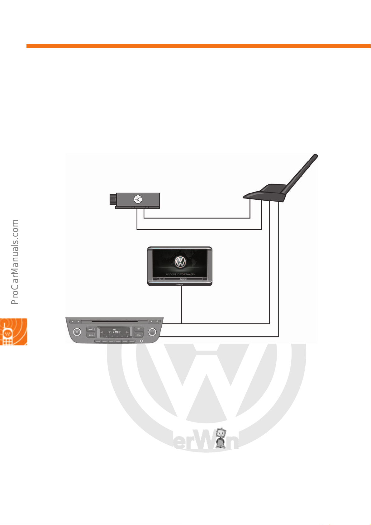
P
r
o
t
e
c
t
e
d
b
y
c
o
p
y
r
i
g
h
t
.
C
o
p
y
i
n
g
f
o
r
p
r
i
v
a
t
e
o
r
c
o
m
m
e
r
c
i
a
l
p
u
r
p
o
s
e
s
,
i
n
p
a
r
t
o
r
i
n
w
h
o
l
e
,
i
s
n
o
t
p
e
r
m
i
t
t
e
d
u
n
l
e
s
s
a
u
t
h
o
r
i
s
e
d
b
y
V
o
l
k
s
w
a
g
e
n
A
G
.
V
o
l
k
s
w
a
g
e
n
A
G
d
o
e
s
n
o
t
g
u
a
r
a
n
t
e
e
o
r
a
c
c
e
p
t
a
n
y
l
i
a
b
i
l
i
t
y
w
i
t
h
r
e
s
p
e
c
t
t
o
t
h
e
c
o
r
r
e
c
t
n
e
s
s
o
f
i
n
f
o
r
m
a
t
i
o
n
i
n
t
h
i
s
d
o
c
u
m
e
n
t
.
C
o
p
y
r
i
g
h
t
b
y
V
o
l
k
s
w
a
g
e
n
A
G
.
Infotainment
GPS
GSM
FM/AM
DAB+
J982
J949
R
R66
R183
R248
s527_064
The aerial systems
The e-up! is equipped with a short rod aerial. This incorporates the telephone, navigation system and auxiliary
heater aerial R66, the radio aerial R248 and the digital radio aerial R183 (DAB+). The short rod aerial also
contains the aerials for the GPS and GSM mobile phone network. Each aerial module communicates with the end
devices via its own cable. The FM/AM connection in the portable navigation and infotainment system J982 is
required for receiving the TMC signal.
Key
J949 Emergency call module control unit and communication unit
J982 Portable navigation and infotainment system
R Radio
R66 Telephone, navigation system and auxiliary heater aerial
R183 Digital radio aerial
R248 Radio aerial
50
Page 51
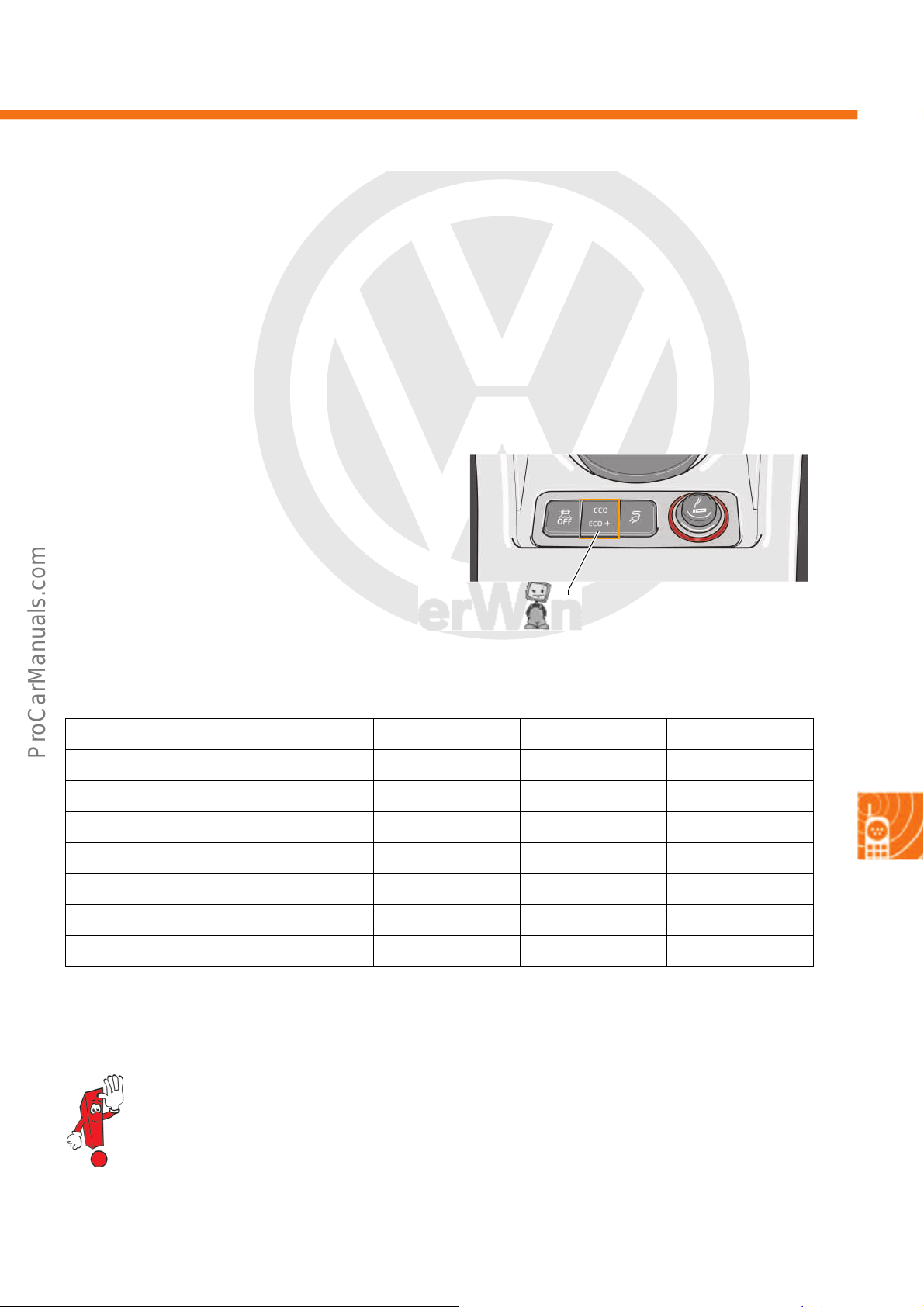
P
r
o
t
e
c
t
e
d
b
y
c
o
p
y
r
i
g
h
t
.
C
o
p
y
i
n
g
f
o
r
p
r
i
v
a
t
e
o
r
c
o
m
m
e
r
c
i
a
l
p
u
r
p
o
s
e
s
,
i
n
p
a
r
t
o
r
i
n
w
h
o
l
e
,
i
s
n
o
t
p
e
r
m
i
t
t
e
d
u
n
l
e
s
s
a
u
t
h
o
r
i
s
e
d
b
y
V
o
l
k
s
w
a
g
e
n
A
G
.
V
o
l
k
s
w
a
g
e
n
A
G
d
o
e
s
n
o
t
g
u
a
r
a
n
t
e
e
o
r
a
c
c
e
p
t
a
n
y
l
i
a
b
i
l
i
t
y
w
i
t
h
r
e
s
p
e
c
t
t
o
t
h
e
c
o
r
r
e
c
t
n
e
s
s
o
f
i
n
f
o
r
m
a
t
i
o
n
i
n
t
h
i
s
d
o
c
u
m
e
n
t
.
C
o
p
y
r
i
g
h
t
b
y
V
o
l
k
s
w
a
g
e
n
A
G
.
Driving mode selection button
s527_066
Driving profile selection
The e-up! is equipped with three driving profiles as standard. The driving profile selection allows the driver to make
vehicle settings according to their preferences. The driver can choose between dynamic (sporty driving style) or
eco-friendly (enhanced range) driving modes. The following driving profiles are available:
• Normal (standard setting)
•ECO
•ECO+
The driving profiles are activated and changed via a
button on the centre console. The driving profile
“Normal” is preset and automatically active every
time the vehicle is started. Depending on the driving
profile selected, the following systems will be
affected:
Systems affected/driving modes Normal ECO ECO+
Air conditioning Normal Reduced Deactivated
Accelerator curve Normal Reduced Flat
Acceleration from 0-100km/h 12.4 s 14.3 s ---
Acceleration from 0-60km/h 4.9 s 6.1 s 7.6 s
Output (peak) 60kW 50kW 40kW
Speed 130km/h 120km/h 95 km/h
Max. starting torque 210Nm 167Nm 133Nm
The driving profiles ECO and ECO+ provide the full 60 kW power for a period of 10 seconds when the
driver depresses the accelerator pedal completely (kickdown function).
51
Page 52
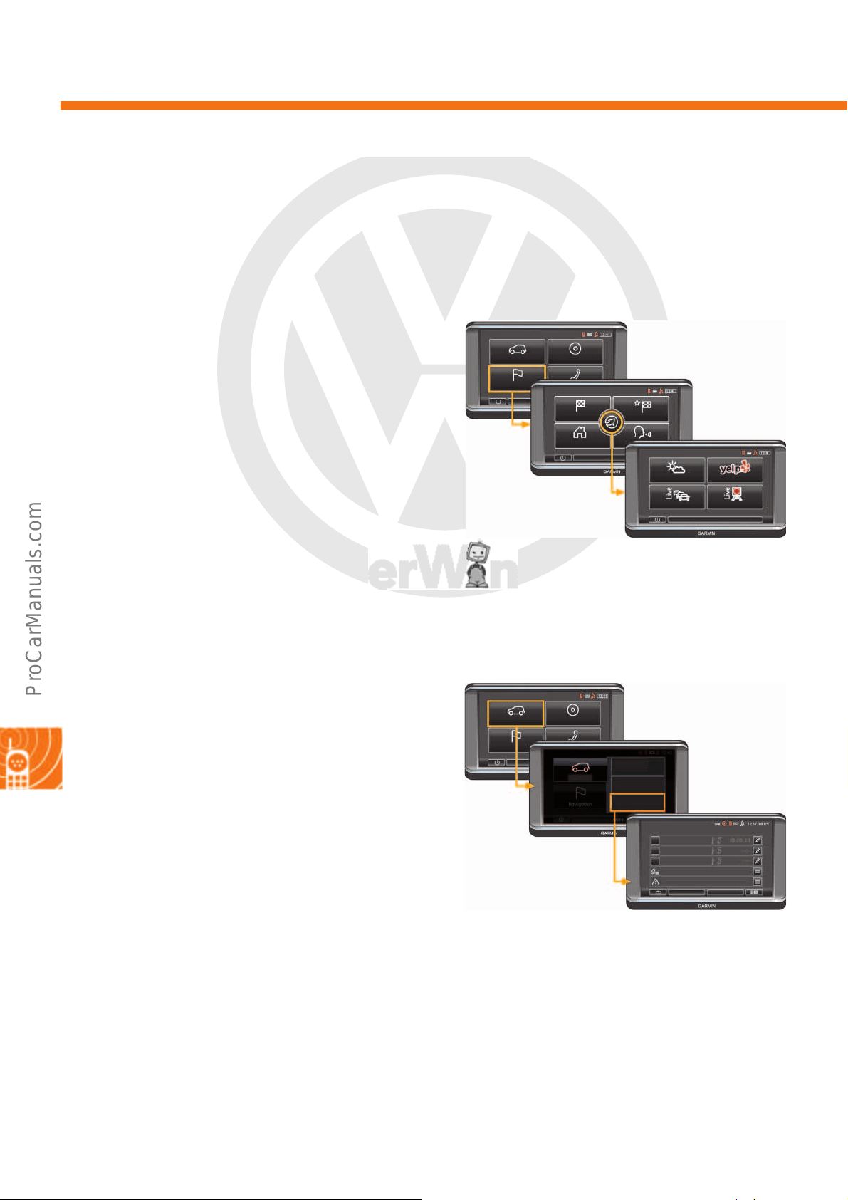
P
r
o
t
e
c
t
e
d
b
y
c
o
p
y
r
i
g
h
t
.
C
o
p
y
i
n
g
f
o
r
p
r
i
v
a
t
e
o
r
c
o
m
m
e
r
c
i
a
l
p
u
r
p
o
s
e
s
,
i
n
p
a
r
t
o
r
i
n
w
h
o
l
e
,
i
s
n
o
t
p
e
r
m
i
t
t
e
d
u
n
l
e
s
s
a
u
t
h
o
r
i
s
e
d
b
y
V
o
l
k
s
w
a
g
e
n
A
G
.
V
o
l
k
s
w
a
g
e
n
A
G
d
o
e
s
n
o
t
g
u
a
r
a
n
t
e
e
o
r
a
c
c
e
p
t
a
n
y
l
i
a
b
i
l
i
t
y
w
i
t
h
r
e
s
p
e
c
t
t
o
t
h
e
c
o
r
r
e
c
t
n
e
s
s
o
f
i
n
f
o
r
m
a
t
i
o
n
i
n
t
h
i
s
d
o
c
u
m
e
n
t
.
C
o
p
y
r
i
g
h
t
b
y
V
o
l
k
s
w
a
g
e
n
A
G
.
Infotainment
s527_068
Vehicle media
Navigation
New destination
My destinations
Home
Weather Local search
Traffic live Speed camera live
Options
Options
s527_108
Messages present
e-Manager
Settings
Charging locations
Departure time 3
Departure time 2
Departure time 1
Vehicle
e-Manager
Electric
shows energy flow, e-Manager, ...
Think Blue. Trainer
Making eco-friendly driving fun!
Onboard computer
Multi-function display
Vehicle media
Navigation
Portable navigation and infotainment system J982
The “maps + more” portable navigation and infotainment system J982 has been produced by Garmin since week
22/2013. It is similar to the regular “maps + more” made by Navigon, but new functions have been added.
Live services
“maps + more” has the following live services which
can be displayed when connected to the Internet:
• Current traffic information
• Speed cameras
•Current weather
• Local searches for specific destinations
For this purpose, it is necessary to pair a datacapable mobile telephone with Bluetooth tethering
support with “maps + more”. The sources for the live
services are the search engine Yelp, the Navteq
traffic information and speed camera service, and
Garmin's own weather forecast.
* The term tethering refers to the action of connecting a
smartphone to a computer or PDA in order to enable it to
access the Internet via GSM/UMTS.
e-Manager
52
The user can control the charging and air
conditioning of the vehicle and program the next
departure time using the e-Manager. The charging
locations with their requirements (available current
strengths) are displayed. The strength of the charging
current depends on the time of departure and the
remaining charging time. From a physics point of
view, it makes sense to use a smaller current strength
over a longer period of time.
Page 53
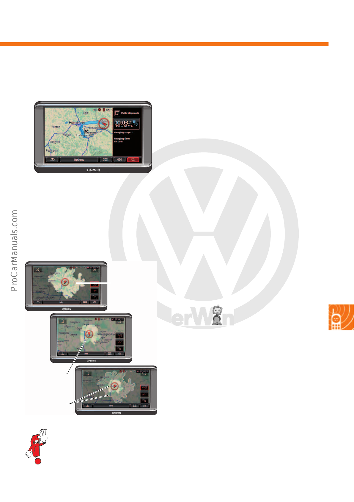
P
r
o
t
e
c
t
e
d
b
y
c
o
p
y
r
i
g
h
t
.
C
o
p
y
i
n
g
f
o
r
p
r
i
v
a
t
e
o
r
c
o
m
m
e
r
c
i
a
l
p
u
r
p
o
s
e
s
,
i
n
p
a
r
t
o
r
i
n
w
h
o
l
e
,
i
s
n
o
t
p
e
r
m
i
t
t
e
d
u
n
l
e
s
s
a
u
t
h
o
r
i
s
e
d
b
y
V
o
l
k
s
w
a
g
e
n
A
G
.
V
o
l
k
s
w
a
g
e
n
A
G
d
o
e
s
n
o
t
g
u
a
r
a
n
t
e
e
o
r
a
c
c
e
p
t
a
n
y
l
i
a
b
i
l
i
t
y
w
i
t
h
r
e
s
p
e
c
t
t
o
t
h
e
c
o
r
r
e
c
t
n
e
s
s
o
f
i
n
f
o
r
m
a
t
i
o
n
i
n
t
h
i
s
d
o
c
u
m
e
n
t
.
C
o
p
y
r
i
g
h
t
b
y
V
o
l
k
s
w
a
g
e
n
A
G
.
Multi-stop route planning
s527_085
s527_087
Combined
display
Range that takes
the return
journey into
account
Simple range
Range display
The “maps + more” system in the e-up! and the ecoup! features multi-stop route planning, which is
accessed via the “Navigation” button.
This means that both the current battery range and
the range for gas operation is taken into account for
the route planning. Charging options (electric and
CNG filling stations) available in the POI data (Point
of Interest = POI) are included or approximate points
named where the vehicle must be charged or
refuelled. The duration of the charging stops is
calculated in the total journey duration and also
displayed separately.
The “maps + more” system in the e-up! features a
range display function in the Navigation menu.
The following can be displayed on the map:
• Basic battery range
• Range that takes into account the return journey to
• A combination of both
the starting point
It is not displayed as a geometrical circle due to the
inclusion of road categories, speed limits and the
topography of the area.
Further information on the menu can be found in Self-study Programme no. 500 “The up!”.
53
Page 54
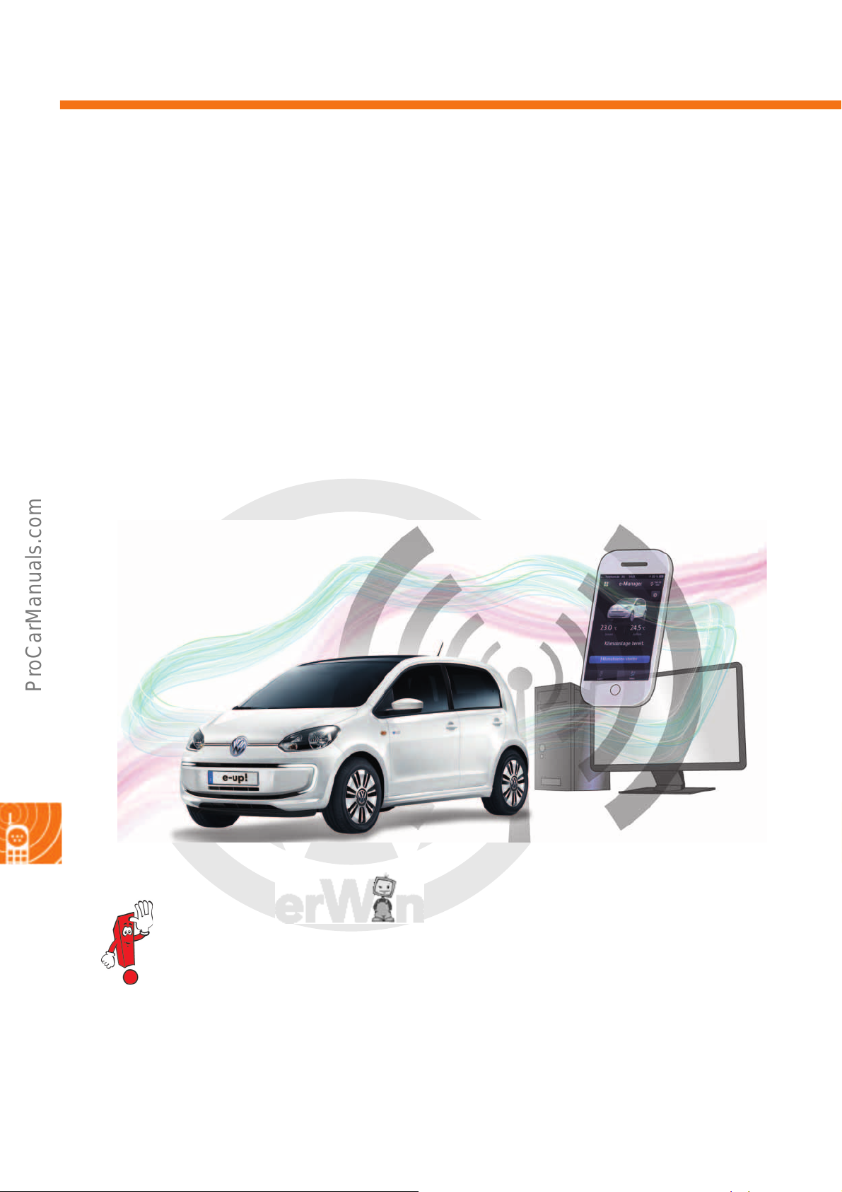
P
r
o
t
e
c
t
e
d
b
y
c
o
p
y
r
i
g
h
t
.
C
o
p
y
i
n
g
f
o
r
p
r
i
v
a
t
e
o
r
c
o
m
m
e
r
c
i
a
l
p
u
r
p
o
s
e
s
,
i
n
p
a
r
t
o
r
i
n
w
h
o
l
e
,
i
s
n
o
t
p
e
r
m
i
t
t
e
d
u
n
l
e
s
s
a
u
t
h
o
r
i
s
e
d
b
y
V
o
l
k
s
w
a
g
e
n
A
G
.
V
o
l
k
s
w
a
g
e
n
A
G
d
o
e
s
n
o
t
g
u
a
r
a
n
t
e
e
o
r
a
c
c
e
p
t
a
n
y
l
i
a
b
i
l
i
t
y
w
i
t
h
r
e
s
p
e
c
t
t
o
t
h
e
c
o
r
r
e
c
t
n
e
s
s
o
f
i
n
f
o
r
m
a
t
i
o
n
i
n
t
h
i
s
d
o
c
u
m
e
n
t
.
C
o
p
y
r
i
g
h
t
b
y
V
o
l
k
s
w
a
g
e
n
A
G
.
Car-Net
s527_089
Mobile online services for the e-up!
Volkswagen has consolidated the mobile online services under the term “Car-Net”. These services were introduced
with the Golf GTI/GTD 2013. In the GTI/GTD 2013, so-called “bright services” were used. In the e-up!, “grey
services” are used for the first time. The difference is that bright services do not require any vehicle-specific data.
Grey services are reliant on vehicle-specific data to guarantee the service functions, such as the vehicle
identification number (VIN), the mileage and information from various control units.
The following grey services are used for the first time in the e-up!:
• Activation and deactivation of the vehicle
charging process
• Remote climate control of the vehicle
•Querying vehicle data
Further information on the “bright services” of Car-Net can be found in Self-study Programme no. 521
“The Golf GTI/GTD 2013”.
• Querying the last parking position
• Querying the vehicle status
• Querying the doors and lighting
54
Page 55

P
r
o
t
e
c
t
e
d
b
y
c
o
p
y
r
i
g
h
t
.
C
o
p
y
i
n
g
f
o
r
p
r
i
v
a
t
e
o
r
c
o
m
m
e
r
c
i
a
l
p
u
r
p
o
s
e
s
,
i
n
p
a
r
t
o
r
i
n
w
h
o
l
e
,
i
s
n
o
t
p
e
r
m
i
t
t
e
d
u
n
l
e
s
s
a
u
t
h
o
r
i
s
e
d
b
y
V
o
l
k
s
w
a
g
e
n
A
G
.
V
o
l
k
s
w
a
g
e
n
A
G
d
o
e
s
n
o
t
g
u
a
r
a
n
t
e
e
o
r
a
c
c
e
p
t
a
n
y
l
i
a
b
i
l
i
t
y
w
i
t
h
r
e
s
p
e
c
t
t
o
t
h
e
c
o
r
r
e
c
t
n
e
s
s
o
f
i
n
f
o
r
m
a
t
i
o
n
i
n
t
h
i
s
d
o
c
u
m
e
n
t
.
C
o
p
y
r
i
g
h
t
b
y
V
o
l
k
s
w
a
g
e
n
A
G
.
Emergency call module control unit and communication unit
s527_120
s527_114
GPS/GSM aerial
connection
Onboard supply connecting
socket
J949
The emergency call module control unit and communication unit J949 is installed in the vehicle as standard.
The installation location is under the front seat on the right-hand side. The control unit J949 contains a permanently
integrated SIM card to access the mobile phone network. The data transfer between the backend system and the
vehicle takes place via this mobile telephone connection. The SIM card is active when it leaves the factory and does
not need to be activated separately. The control unit J949 is a participant in the convenience CAN data bus.
Function
The control unit J949 transfers the relevant data collected from the control units in the network to the backend
system. In the opposite direction, it receives the commands from the backend system and forwards them to the
relevant control units. The emergency call module control unit and communication unit J949 is active even when
the ignition is off and if necessary, it wakes up other relevant CAN data bus participants.
The term “backend” comes from the IT sector and describes a database system. All data relevant to the
vehicle and customer are saved here. The backend system processes the saved data and forwards
them to the vehicle or the smartphone.
55
Page 56
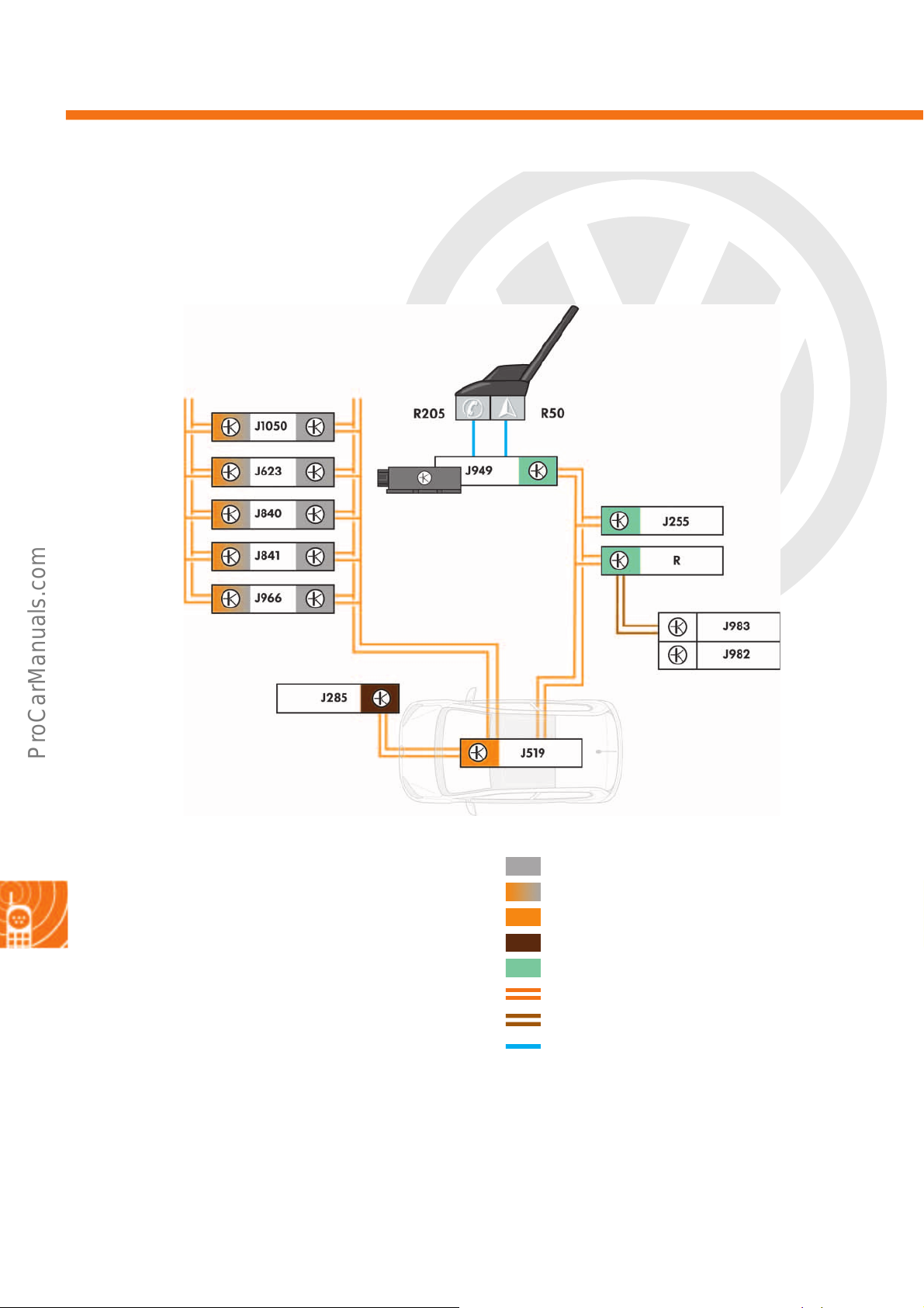
P
r
o
t
e
c
t
e
d
b
y
c
o
p
y
r
i
g
h
t
.
C
o
p
y
i
n
g
f
o
r
p
r
i
v
a
t
e
o
r
c
o
m
m
e
r
c
i
a
l
p
u
r
p
o
s
e
s
,
i
n
p
a
r
t
o
r
i
n
w
h
o
l
e
,
i
s
n
o
t
p
e
r
m
i
t
t
e
d
u
n
l
e
s
s
a
u
t
h
o
r
i
s
e
d
b
y
V
o
l
k
s
w
a
g
e
n
A
G
.
V
o
l
k
s
w
a
g
e
n
A
G
d
o
e
s
n
o
t
g
u
a
r
a
n
t
e
e
o
r
a
c
c
e
p
t
a
n
y
l
i
a
b
i
l
i
t
y
w
i
t
h
r
e
s
p
e
c
t
t
o
t
h
e
c
o
r
r
e
c
t
n
e
s
s
o
f
i
n
f
o
r
m
a
t
i
o
n
i
n
t
h
i
s
d
o
c
u
m
e
n
t
.
C
o
p
y
r
i
g
h
t
b
y
V
o
l
k
s
w
a
g
e
n
A
G
.
Car-Net
s527_118
Network for the emergency call module control unit and
communication unit J949.
Key
J255 Climatronic control unit
J285 Control unit in dash panel insert
J519 Onboard supply control unit
J623 Engine (motor) control unit
J840 Battery regulation control unit
J841 Electric drive control unit
J949 Emergency call module control unit and
communication unit
J966 Charge voltage control unit for
high-voltage battery
J982 Portable navigation and infotainment system
J983 Interface for portable navigation
and infotainment system
J1050 Control unit for high-voltage battery charging unit
R Radio
R50 GPS aerial
R205 GSM aerial
Powertrain CAN data bus
Hybrid CAN data bus
Diagnostic CAN data bus
Dash panel insert CAN data bus
Convenience CAN data bus
CAN data bus wire
Unidirectional LIN data bus wire
Actuator wire
56
Page 57
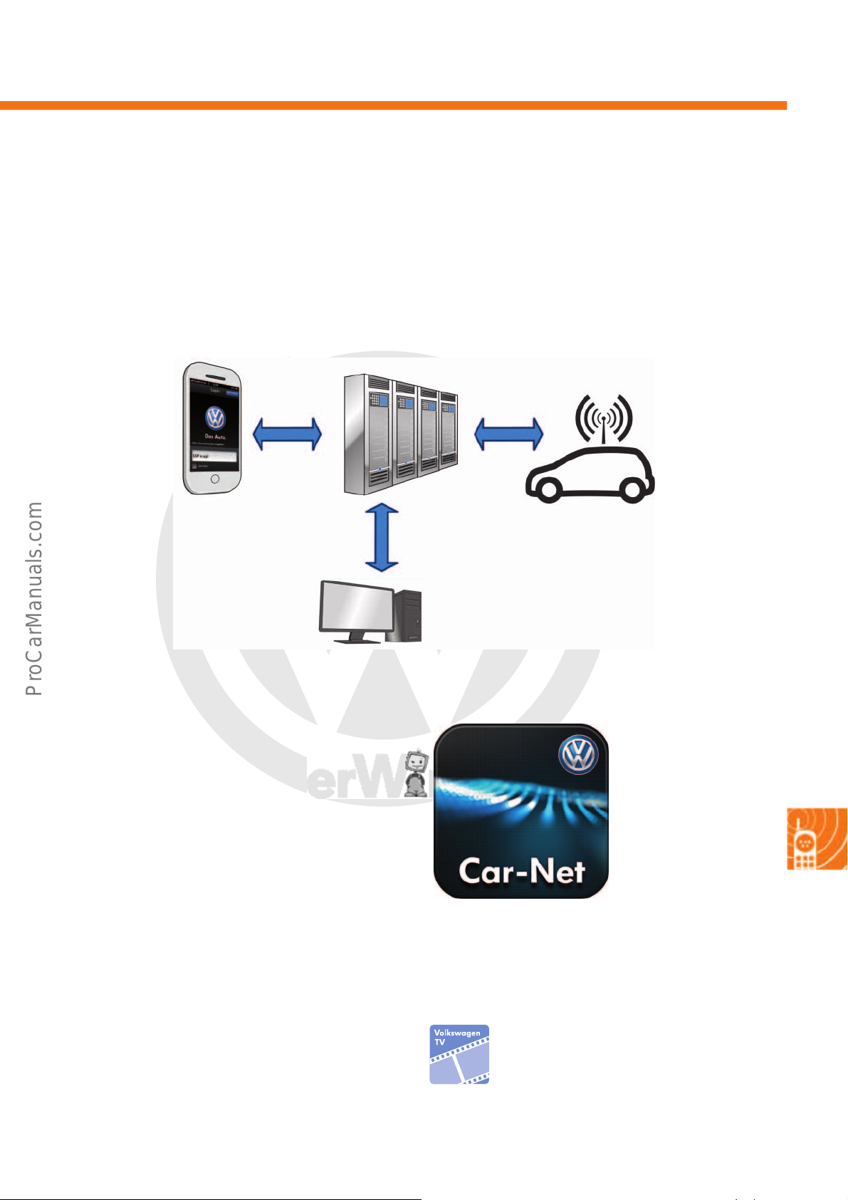
P
r
o
t
e
c
t
e
d
b
y
c
o
p
y
r
i
g
h
t
.
C
o
p
y
i
n
g
f
o
r
p
r
i
v
a
t
e
o
r
c
o
m
m
e
r
c
i
a
l
p
u
r
p
o
s
e
s
,
i
n
p
a
r
t
o
r
i
n
w
h
o
l
e
,
i
s
n
o
t
p
e
r
m
i
t
t
e
d
u
n
l
e
s
s
a
u
t
h
o
r
i
s
e
d
b
y
V
o
l
k
s
w
a
g
e
n
A
G
.
V
o
l
k
s
w
a
g
e
n
A
G
d
o
e
s
n
o
t
g
u
a
r
a
n
t
e
e
o
r
a
c
c
e
p
t
a
n
y
l
i
a
b
i
l
i
t
y
w
i
t
h
r
e
s
p
e
c
t
t
o
t
h
e
c
o
r
r
e
c
t
n
e
s
s
o
f
i
n
f
o
r
m
a
t
i
o
n
i
n
t
h
i
s
d
o
c
u
m
e
n
t
.
C
o
p
y
r
i
g
h
t
b
y
V
o
l
k
s
w
a
g
e
n
A
G
.
Data transfer
s527_074
GSM
Emergency call module control unit
and communication unit J949
Backend system
PC
Internet
Car-Net app
GSM
s527_121
Symbol of the Car-Net app
Data transfer never takes places between the end device and the vehicle directly. The vehicle data are recorded in
a backend system. The user accesses the data via a smartphone, tablet or computer. The connection is via the
Internet or GSM mobile phone network.
Car-Net app
With the Car-Net app, the user has the option to
control certain functions of their e-up! remotely. A
smartphone or tablet is required to use the Car-Net
app. The Car-Net app is available for the Apple
iPhone in the Apple App Store and can also be used
with an iPad. The supported operating systems are
currently iOS 5, iOS 6 and iOS 7. The app is
available in the Google Play Store for Android
devices. The operating systems 2.3, 4.0 and higher
are currently supported.
Further information on the app can be
found via Volkswagen TV.
57
Page 58
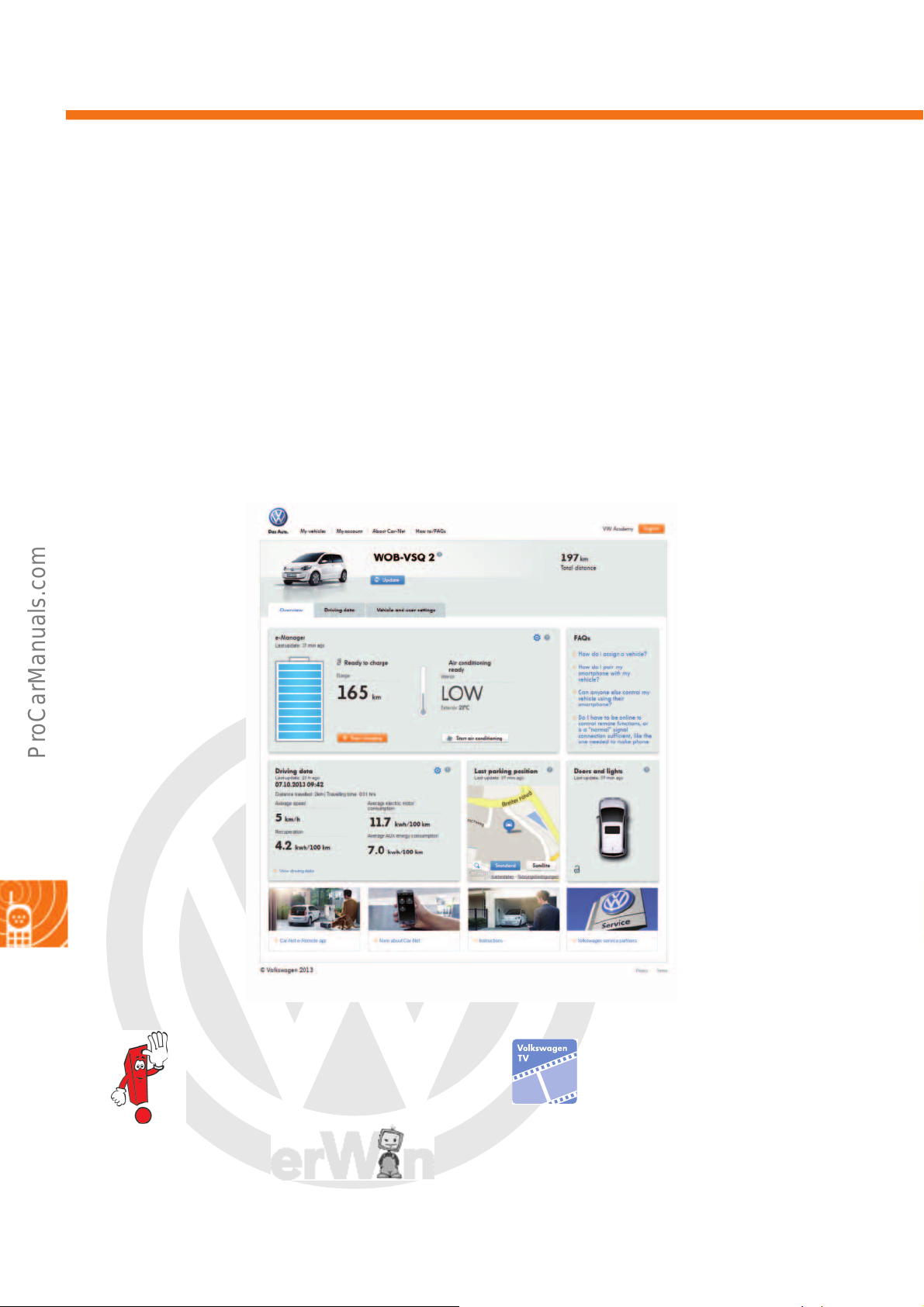
P
r
o
t
e
c
t
e
d
b
y
c
o
p
y
r
i
g
h
t
.
C
o
p
y
i
n
g
f
o
r
p
r
i
v
a
t
e
o
r
c
o
m
m
e
r
c
i
a
l
p
u
r
p
o
s
e
s
,
i
n
p
a
r
t
o
r
i
n
w
h
o
l
e
,
i
s
n
o
t
p
e
r
m
i
t
t
e
d
u
n
l
e
s
s
a
u
t
h
o
r
i
s
e
d
b
y
V
o
l
k
s
w
a
g
e
n
A
G
.
V
o
l
k
s
w
a
g
e
n
A
G
d
o
e
s
n
o
t
g
u
a
r
a
n
t
e
e
o
r
a
c
c
e
p
t
a
n
y
l
i
a
b
i
l
i
t
y
w
i
t
h
r
e
s
p
e
c
t
t
o
t
h
e
c
o
r
r
e
c
t
n
e
s
s
o
f
i
n
f
o
r
m
a
t
i
o
n
i
n
t
h
i
s
d
o
c
u
m
e
n
t
.
C
o
p
y
r
i
g
h
t
b
y
V
o
l
k
s
w
a
g
e
n
A
G
.
Car-Net
s527_117
Customer portal homepage
Customer portal
The customer portal can be accessed at www.volkswagen.com/car-net. The following content and functions are
available in the portal:
• Registration of vehicles and simultaneous
activation of the Car-Net services
• Vehicle management (e.g. fleet)
• Administration of user accounts
• Operation of Car-Net functions
To use Car-Net, both user and vehicle must be registered in the customer portal.
If the user owns several vehicles, up to six
vehicles can be registered per user
account. If several people use the vehicle,
up to five users can be registered per
vehicle.
•Service descriptions
• Settings and options
• Frequently asked questions
• Further information related to Car-Net
See the relevant Volkswagen TV entry for
information on using the customer portal.
58
Page 59
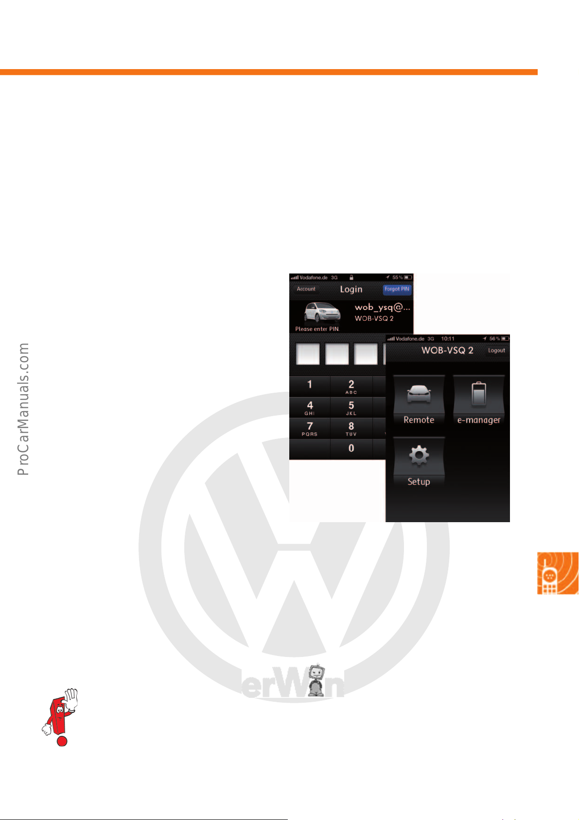
P
r
o
t
e
c
t
e
d
b
y
c
o
p
y
r
i
g
h
t
.
C
o
p
y
i
n
g
f
o
r
p
r
i
v
a
t
e
o
r
c
o
m
m
e
r
c
i
a
l
p
u
r
p
o
s
e
s
,
i
n
p
a
r
t
o
r
i
n
w
h
o
l
e
,
i
s
n
o
t
p
e
r
m
i
t
t
e
d
u
n
l
e
s
s
a
u
t
h
o
r
i
s
e
d
b
y
V
o
l
k
s
w
a
g
e
n
A
G
.
V
o
l
k
s
w
a
g
e
n
A
G
d
o
e
s
n
o
t
g
u
a
r
a
n
t
e
e
o
r
a
c
c
e
p
t
a
n
y
l
i
a
b
i
l
i
t
y
w
i
t
h
r
e
s
p
e
c
t
t
o
t
h
e
c
o
r
r
e
c
t
n
e
s
s
o
f
i
n
f
o
r
m
a
t
i
o
n
i
n
t
h
i
s
d
o
c
u
m
e
n
t
.
C
o
p
y
r
i
g
h
t
b
y
V
o
l
k
s
w
a
g
e
n
A
G
.
Car-Net services in the e-up!
s527_127
The Car-Net services offer the user the option to call up status information for the vehicle and control functions
remotely via the Car-Net app or the customer portal. The functions of the individual services are explained below
using the example of the smartphone app. The same services can also be accessed using the customer portal and
work in the same way.
Start screen
The start screen appears after the user has logged
into the Car-Net app with their e-mail address and
PIN. Three menu items appear:
1. Menu item: Vehicle
2. Menu item: e-Manager
3. Menu item: Setup
Within each menu item, individual services can be
selected via buttons at the bottom of the screen.
After logging in, all services are displayed on the
homepage in the customer portal.
Menu item “e-Manager”
The user can control the charging and air conditioning of the vehicle using the e-Manager.
The settings are made using the Car-Net app or the customer portal, transferred to the backend system and
forwarded to the vehicle from there.
Only charging and air conditioning can be remotely controlled via the Car-Net app or the customer
portal.
59
Page 60
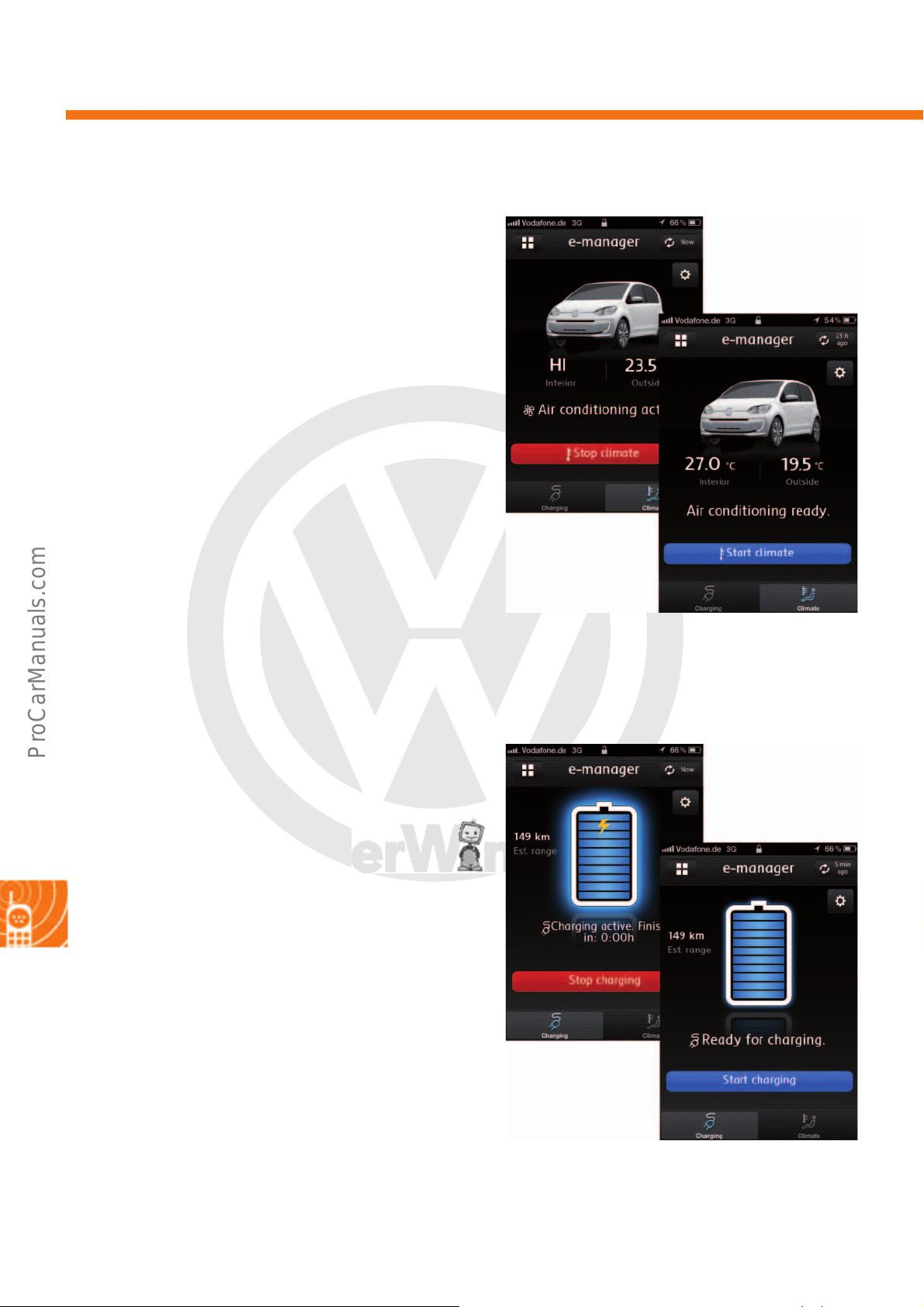
P
r
o
t
e
c
t
e
d
b
y
c
o
p
y
r
i
g
h
t
.
C
o
p
y
i
n
g
f
o
r
p
r
i
v
a
t
e
o
r
c
o
m
m
e
r
c
i
a
l
p
u
r
p
o
s
e
s
,
i
n
p
a
r
t
o
r
i
n
w
h
o
l
e
,
i
s
n
o
t
p
e
r
m
i
t
t
e
d
u
n
l
e
s
s
a
u
t
h
o
r
i
s
e
d
b
y
V
o
l
k
s
w
a
g
e
n
A
G
.
V
o
l
k
s
w
a
g
e
n
A
G
d
o
e
s
n
o
t
g
u
a
r
a
n
t
e
e
o
r
a
c
c
e
p
t
a
n
y
l
i
a
b
i
l
i
t
y
w
i
t
h
r
e
s
p
e
c
t
t
o
t
h
e
c
o
r
r
e
c
t
n
e
s
s
o
f
i
n
f
o
r
m
a
t
i
o
n
i
n
t
h
i
s
d
o
c
u
m
e
n
t
.
C
o
p
y
r
i
g
h
t
b
y
V
o
l
k
s
w
a
g
e
n
A
G
.
Car-Net
s527_095
s527_093
“Air conditioning” button
This function offers the user the option to start the
instant air conditioning for their vehicle remotely. The
signal route in the vehicle appears as follows:
1. The emergency call module control unit and
communication unit J949 processes the request
and forwards the signal to the control unit for
high-voltage battery charging unit J1050.
2. The J1050 starts up the high-voltage system using
the engine (motor) control unit J623 and forwards
the signal to the Climatronic control unit J255.
3. The J1050 closes the high-voltage contactors. The
high-voltage system is now active.
4. Air conditioning starts.
Remote-controlled air conditioning can be carried out
regardless of whether the charging plug is plugged in
or not.
“Charging” button
The charging process for the high-voltage battery can
be started or ended via this function. The signal route
in this case is as follows:
1. The J949 receives the signal and forwards it to the
charge voltage control unit for high-voltage
battery J966.
2. The J966 checks whether a charging plug is
plugged in. If the plug is recognised, the signal is
forwarded to the J1050.
3. The J1050 starts up the high-voltage system via
the J623.
4. The battery regulation control unit J840 closes the
high-voltage contactors. The high-voltage system
is now active.
5. The high-voltage battery 1 AX2 charges.
6. The J840 prepares information about the charge
level and the remaining charge time.
60
Page 61
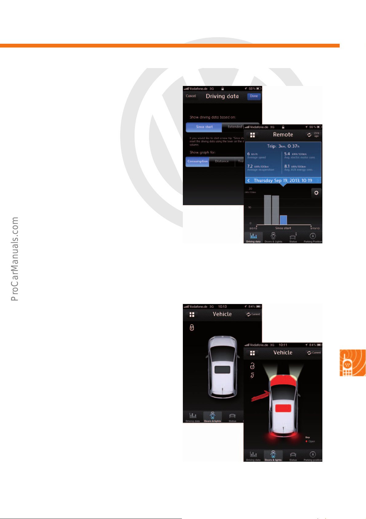
P
r
o
t
e
c
t
e
d
b
y
c
o
p
y
r
i
g
h
t
.
C
o
p
y
i
n
g
f
o
r
p
r
i
v
a
t
e
o
r
c
o
m
m
e
r
c
i
a
l
p
u
r
p
o
s
e
s
,
i
n
p
a
r
t
o
r
i
n
w
h
o
l
e
,
i
s
n
o
t
p
e
r
m
i
t
t
e
d
u
n
l
e
s
s
a
u
t
h
o
r
i
s
e
d
b
y
V
o
l
k
s
w
a
g
e
n
A
G
.
V
o
l
k
s
w
a
g
e
n
A
G
d
o
e
s
n
o
t
g
u
a
r
a
n
t
e
e
o
r
a
c
c
e
p
t
a
n
y
l
i
a
b
i
l
i
t
y
w
i
t
h
r
e
s
p
e
c
t
t
o
t
h
e
c
o
r
r
e
c
t
n
e
s
s
o
f
i
n
f
o
r
m
a
t
i
o
n
i
n
t
h
i
s
d
o
c
u
m
e
n
t
.
C
o
p
y
r
i
g
h
t
b
y
V
o
l
k
s
w
a
g
e
n
A
G
.
s527_097
s527_099
Menu item “Vehicle”
Here, the user can view data about their vehicle and
their driving behaviour.
“Driving data” button
This service displays selected driving data, such as
consumption, driving time and driving distance, in
both table and graphic form. The user can select
whether the data should be displayed in the customer
portal from the registration of the vehicle in the portal
or from the start. The data for this service are
transferred to the backend system by the control unit
in dash panel insert J285 via the J949 following an
ignition change (T 15 on/off).
“Doors & lights” button
This function shows the user whether the vehicle is
locked or if doors, bonnet or tailgate are open. If it is
locked, a padlock symbol is displayed. Open doors,
bonnet or tailgate are coloured red. It also shows
whether the vehicle lights are switched on. The light
beam of the headlights and rear lights make this
visible.
If a charging plug is connected, a plug symbol is
displayed. Data concerning open doors and
switched-on lighting are provided by the onboard
supply control unit J519 and the J285. J966
recognises the charging plug.
61
Page 62
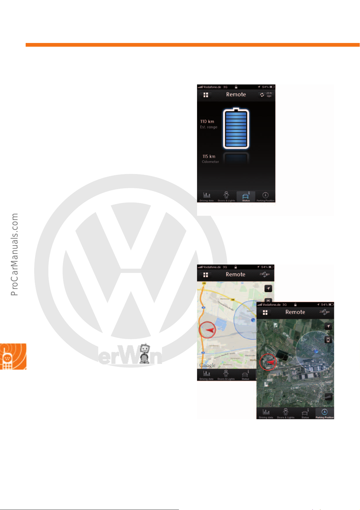
P
r
o
t
e
c
t
e
d
b
y
c
o
p
y
r
i
g
h
t
.
C
o
p
y
i
n
g
f
o
r
p
r
i
v
a
t
e
o
r
c
o
m
m
e
r
c
i
a
l
p
u
r
p
o
s
e
s
,
i
n
p
a
r
t
o
r
i
n
w
h
o
l
e
,
i
s
n
o
t
p
e
r
m
i
t
t
e
d
u
n
l
e
s
s
a
u
t
h
o
r
i
s
e
d
b
y
V
o
l
k
s
w
a
g
e
n
A
G
.
V
o
l
k
s
w
a
g
e
n
A
G
d
o
e
s
n
o
t
g
u
a
r
a
n
t
e
e
o
r
a
c
c
e
p
t
a
n
y
l
i
a
b
i
l
i
t
y
w
i
t
h
r
e
s
p
e
c
t
t
o
t
h
e
c
o
r
r
e
c
t
n
e
s
s
o
f
i
n
f
o
r
m
a
t
i
o
n
i
n
t
h
i
s
d
o
c
u
m
e
n
t
.
C
o
p
y
r
i
g
h
t
b
y
V
o
l
k
s
w
a
g
e
n
A
G
.
Car-Net
s527_101
s527_103
“Status” button
Under Status, the user is shown the charge level of the
high-voltage battery, the remaining range and the
entire distance travelled. The data for this service are
provided by the J840 and the J285.
“Parking position” button
Following an ignition change (T 15 on/off), the most
recent parking position is saved in the backend
system. Under the tab “Parking position”, the position
is shown in a standard map view. There is also the
option of displaying it on a satellite map. The arrow in
the red circle represents the position of the vehicle.
The position of the end device is shown as a blue dot.
The GPS data are delivered directly from J949.
62
Page 63
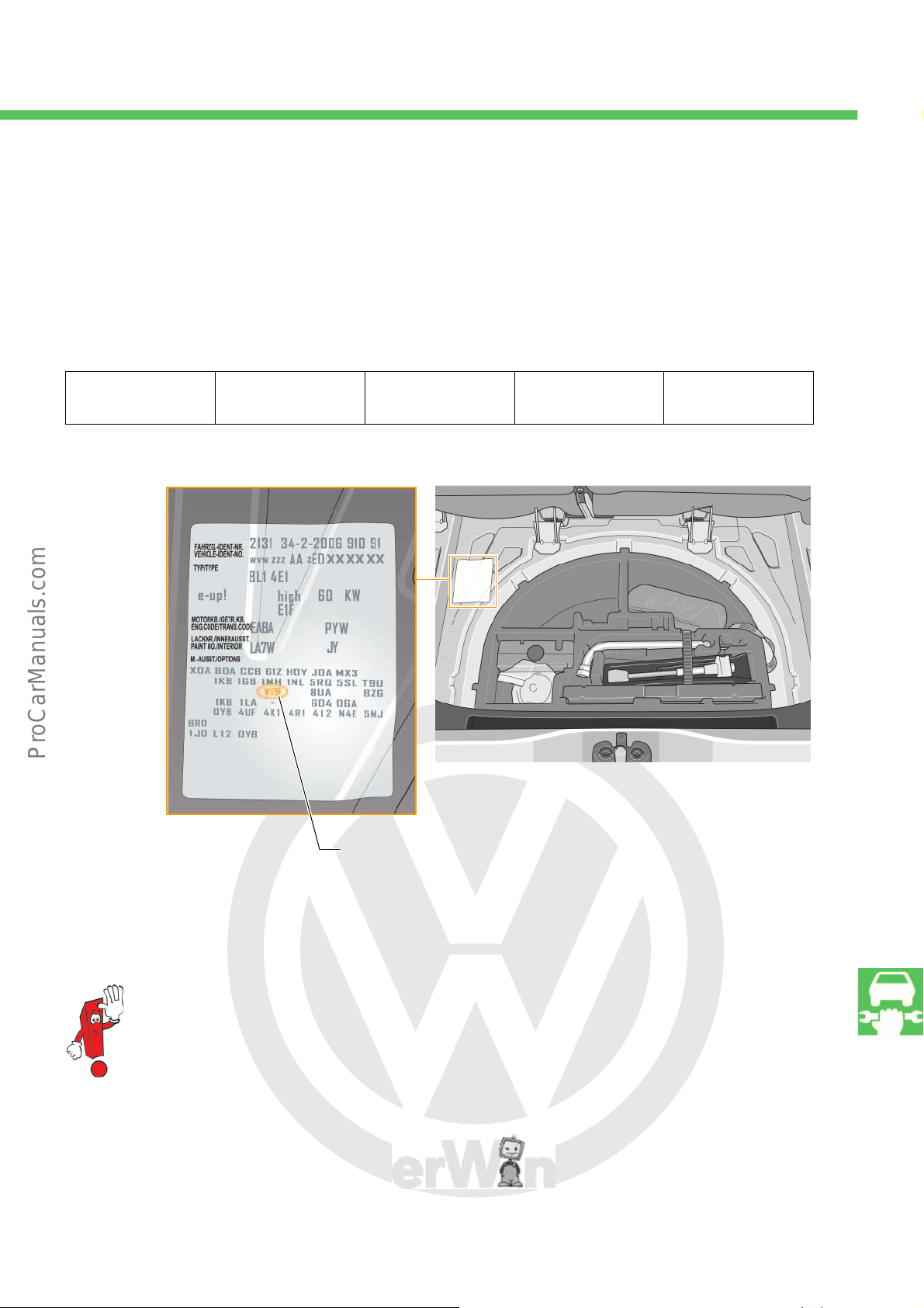
P
r
o
t
e
c
t
e
d
b
y
c
o
p
y
r
i
g
h
t
.
C
o
p
y
i
n
g
f
o
r
p
r
i
v
a
t
e
o
r
c
o
m
m
e
r
c
i
a
l
p
u
r
p
o
s
e
s
,
i
n
p
a
r
t
o
r
i
n
w
h
o
l
e
,
i
s
n
o
t
p
e
r
m
i
t
t
e
d
u
n
l
e
s
s
a
u
t
h
o
r
i
s
e
d
b
y
V
o
l
k
s
w
a
g
e
n
A
G
.
V
o
l
k
s
w
a
g
e
n
A
G
d
o
e
s
n
o
t
g
u
a
r
a
n
t
e
e
o
r
a
c
c
e
p
t
a
n
y
l
i
a
b
i
l
i
t
y
w
i
t
h
r
e
s
p
e
c
t
t
o
t
h
e
c
o
r
r
e
c
t
n
e
s
s
o
f
i
n
f
o
r
m
a
t
i
o
n
i
n
t
h
i
s
d
o
c
u
m
e
n
t
.
C
o
p
y
r
i
g
h
t
b
y
V
o
l
k
s
w
a
g
e
n
A
G
.
Service
VI9 means that the service display for an electric vehicle is activated after
30,000 km or a fixed 2 years.
s527_130
s527_128
Maintenance intervals for the e-up!
Inspection of the e-up! is dependent on the mileage and the number of months driven. The first inspection takes
place after 30,000 km or 24 months, and then afterwards every 12 months or every 30,000 km, whichever comes
first. The abbreviation VI9 specifically indicates an electric vehicle. The brake fluid inspection intervals remain as
normal: for the first time after 3 years and then every 2 years.
Inspection and
additional works
30,000km or
24 months
Please observe the current information in the service literature.
45,000km or
36 months
60,000km or
48 months
75,000km or
60 months
63
Page 64
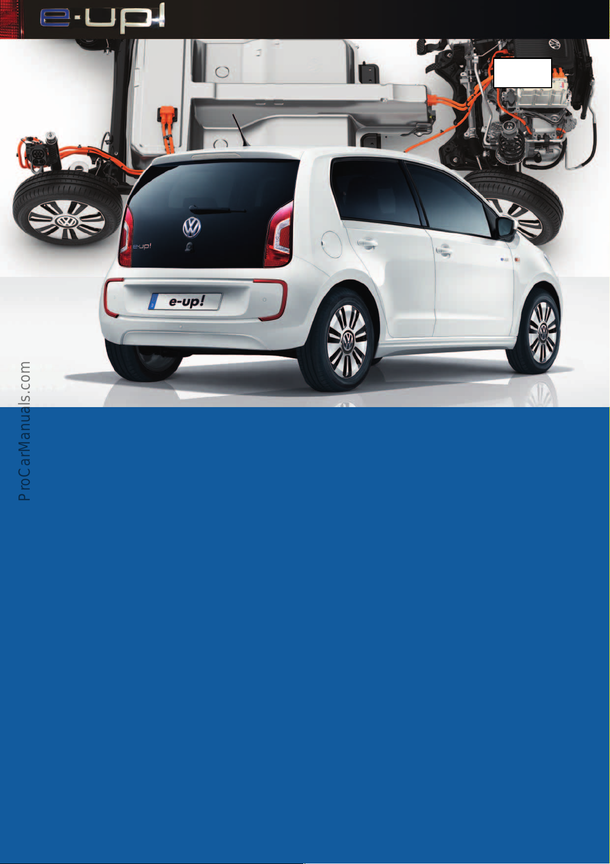
P
r
o
t
e
c
t
e
d
b
y
c
o
p
y
r
i
g
h
t
.
C
o
p
y
i
n
g
f
o
r
p
r
i
v
a
t
e
o
r
c
o
m
m
e
r
c
i
a
l
p
u
r
p
o
s
e
s
,
i
n
p
a
r
t
o
r
i
n
w
h
o
l
e
,
i
s
n
o
t
p
e
r
m
i
t
t
e
d
u
n
l
e
s
s
a
u
t
h
o
r
i
s
e
d
b
y
V
o
l
k
s
w
a
g
e
n
A
G
.
V
o
l
k
s
w
a
g
e
n
A
G
d
o
e
s
n
o
t
g
u
a
r
a
n
t
e
e
o
r
a
c
c
e
p
t
a
n
y
l
i
a
b
i
l
i
t
y
w
i
t
h
r
e
s
p
e
c
t
t
o
t
h
e
c
o
r
r
e
c
t
n
e
s
s
o
f
i
n
f
o
r
m
a
t
i
o
n
i
n
t
h
i
s
d
o
c
u
m
e
n
t
.
C
o
p
y
r
i
g
h
t
b
y
V
o
l
k
s
w
a
g
e
n
A
G
.
527
© VOLKSWAGEN AG, Wolfsburg
All rights and rights to make technical alterations reserved.
000.2812.84.20 Technical status 01/2014
Volkswagen AG
After Sales Qualification
Service Training VSQ-2
Brieffach 1995
D-38436 Wolfsburg
❀ This paper was manufactured from pulp that was bleached without the use of chlorine.
 Loading...