

Page 1
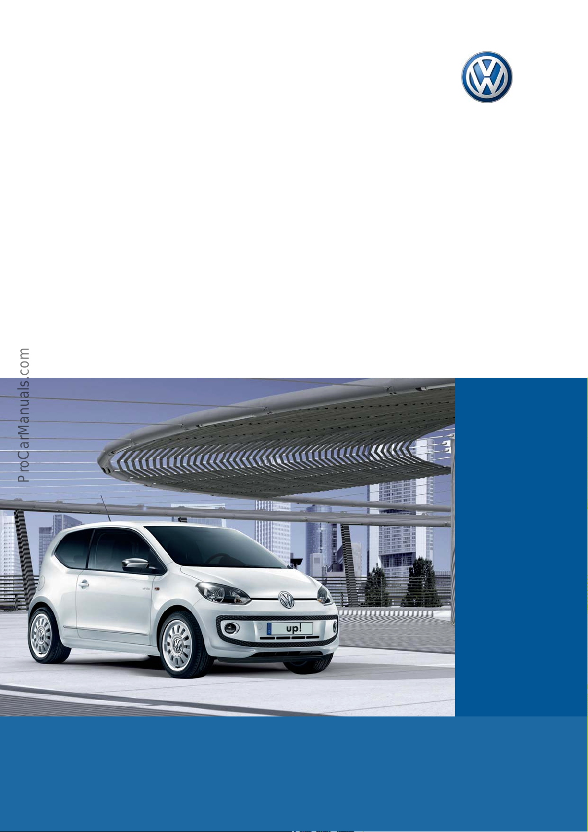
Service Training
Self-study programme 500
The up!
Page 2
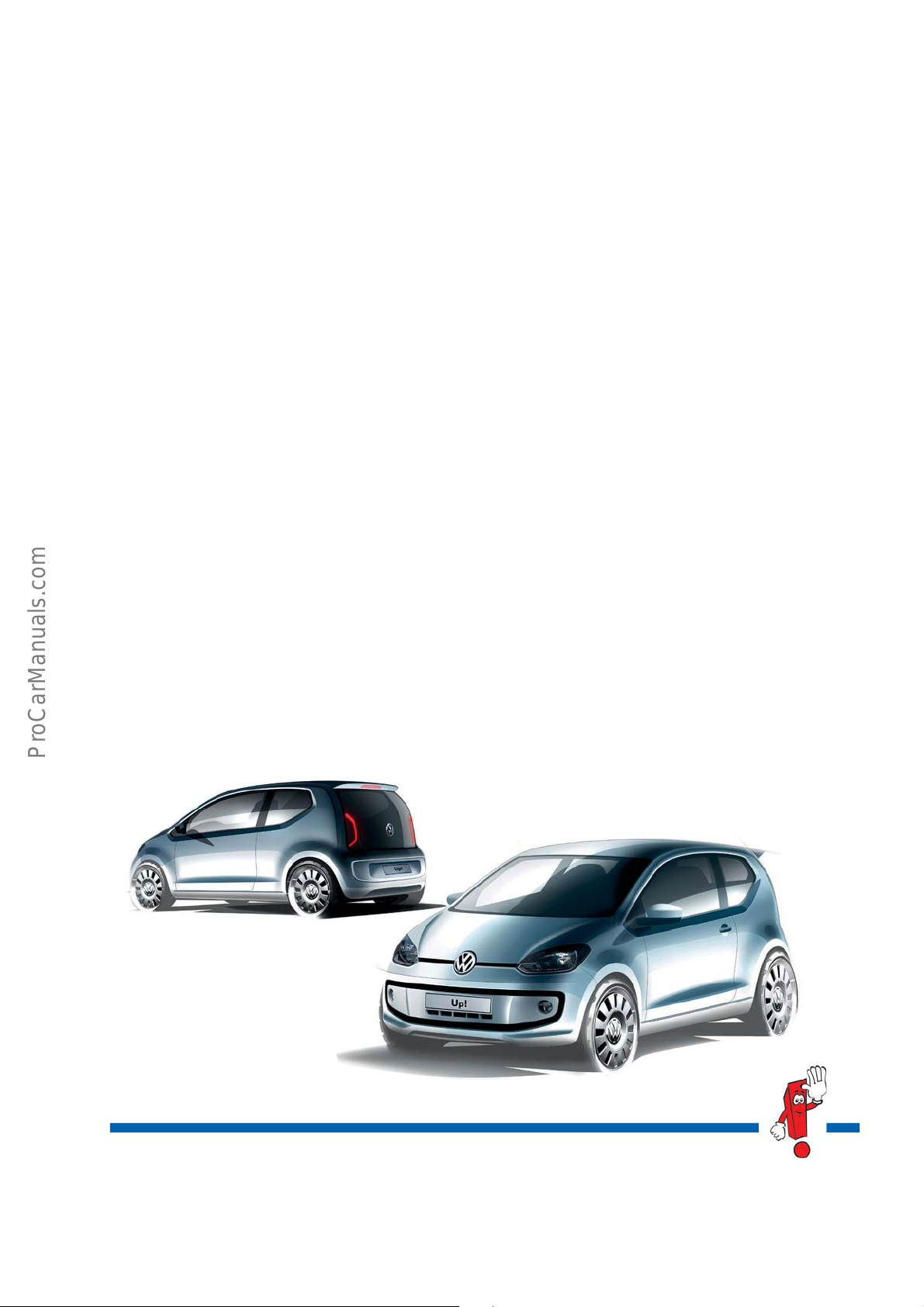
The up! – a major player in the compact class
With the up! as the entry level model, a completely new vehicle has been developed. Having sati
sfied the highest
safety and quality standards, the up! is characterised by its compact outer dimensions which allow use of the
interior space to be maximised, a new engine generation available in two versions, a clean, powerful design and
new technical details.
i
The new three-cylinder petrol eng
ne has a power output of 44 kW or 55 kW. It is also available in a version
featuring BlueMotion technology with the start/stop system. This generation of engines will be employing a 50 kW
natural gas
The engines are combined with the ne
engine at a later stage.
w
weight and space optimised 5-speed manual or automated manual
gearbox.
The city emergency braking function, available as an option, is activated at speeds below 30 km/h and uses a
laser
sensor to detect vehicles travelling in front. When the need arises, it automatically initiates a braking
manoeuvre and can contribute to preventing an imminent front-end collision or minimise the damage one causes.
The optional navigation and infotainment system “maps + more
” has been especially developed for the up! It
supports the Radio function, while also including functions for Navigation, Phone and Car Info. The fixture for
securing the mobile device on the dash panel ensures absolute ease of operation, forming the interface to the
vehicle.
The passenger compartment captivates with its
logical operati
ng concept, providing an optimal view of the control
elements, a storage concept and a boot with a volume of 251 litres.
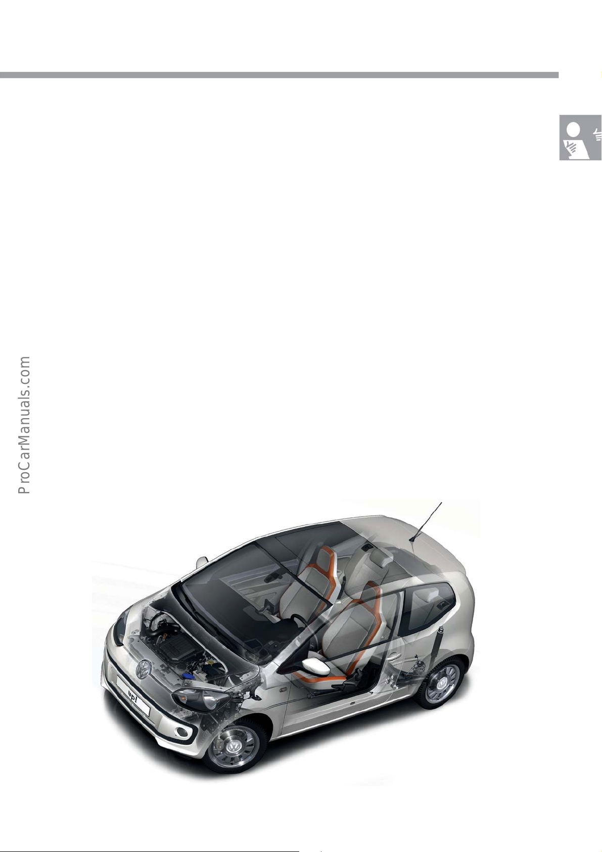
The self-study programme presents the
design and function of
new developments!
The content will not be updated.
Current testing, setting and repair instructions can
be found in the provided service literature.
s500_001
Important
note
2
Page 3

Contents
Introduction . . . . . . . . . . . . . . . . . . . . . . . . . . . . . . . . . . . . . . . . . . . . . . . . . . . . . 4
Body . . . . . . . . . . . . . . . . . . . . . . . . . . . . . . . . . . . . . . . . . . . . . . . . . . . . . . . . . . 8
Occupant Protection
Engines
Power Transmission . . . . . . . . . . . . . . . . . . . . . . . . . . . . . . . . . . . . . . . . . . . . . 17
Running Gear . . . . . . . . . . . . . . . . . . . . . . . . . . . . . . . . . . . . . . . . . . . . . . . . . . 18
Heating and Air Conditioning . . . . . . . . . . . . . . . . . . . . . . . . . . . . . . . . . . . . . 24
Electrical System . . . . . . . . . . . . . . . . . . . . . . . . . . . . . . . . . . . . . . . . . . . . . . . . 27
. . . . . . . . . . . . . . . . . . . . . . . . . . . . . . . . . . . . . . . . . . . . . 15
. . . . . . . . . . . . . . . . . . . . . . . . . . . . . . . . . . . . . . . . . . . . . . . . . . . . . . . 16
Convenience Electronics . . . . . . . . . . . . . . . . . . . . . . . . . . . . . . . . . . . . . . . . . . 30
Infotainment . . . . . . . . . . . . . . . . . . . . . . . . . . . . . . . . . . . . . . . . . . . . . . . . . . . 33
3
Page 4
Introduction
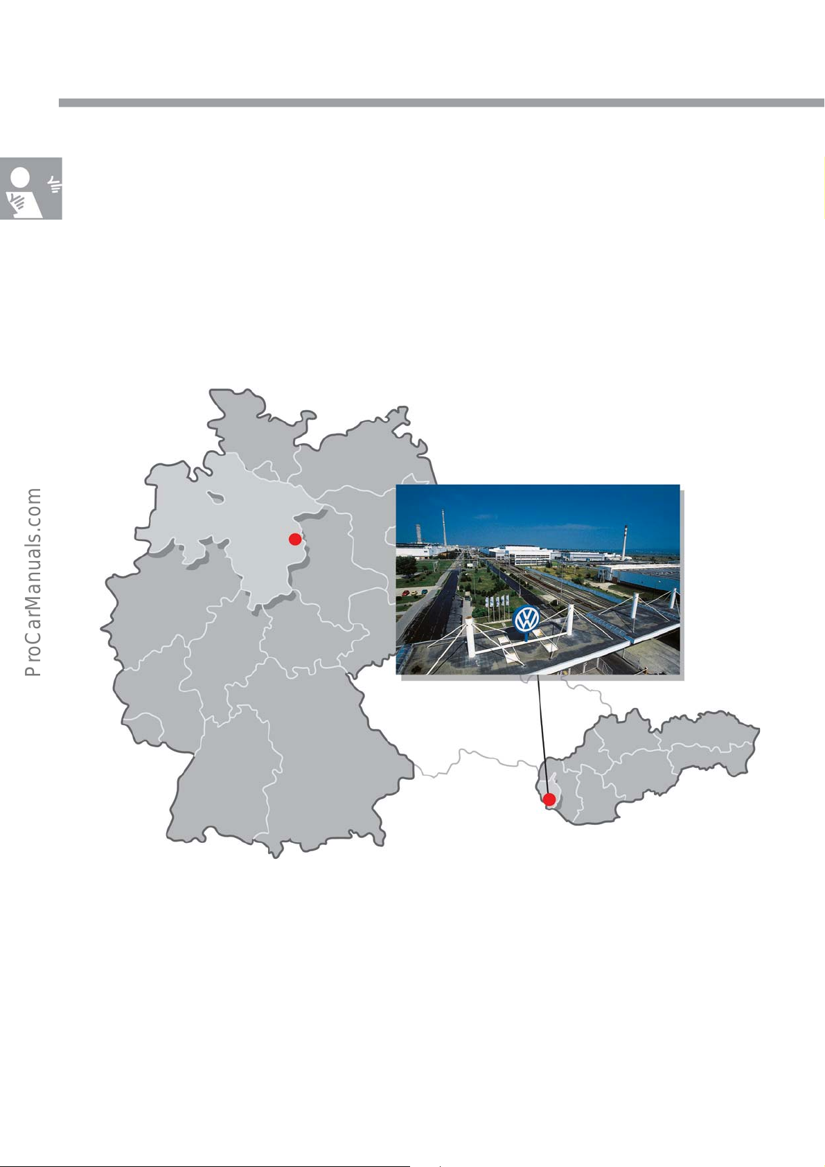
The Bratislava production site
Production of the up!, the new compact car, was launched in August 2011. Production is being carried out in the
Bratislava plant in Slovakia, which already produces vehicle models for Volkswagen, Skoda, Seat, Audi, bodies for
Porsche, and gearboxes.
Wolfsburg
Bratislava
s500_002
4
Page 5
Overview of equipment features
The overview shows you a range of standard and optional equipment for the new up!
The range of options builds on the standard e
“move up!” equipment line as well as the “high up!”
Here is some of the equipment featured in the up!:
quipment “take up!” to form the
. These may vary from country to country.
• Automatic flashing brake lights in the event
• Electronic stabilisation progra
• Head and side airbags combined at the front
• Electromechanical power steering
• City emergency braking function, optional
• Manual air conditioning system,
• RCD 215 radio system, optional
• Navigation and infotainment system “maps +
• up! boxes – innovative collapsible portab
box, all optional
• Automated manual gearbox, optional
• Tilting panorama sunroof, optional
• Four doors with rear vent windows, optional
m ESP incl. ABS and ASR
onal
opti
of hard braking
mor
e”, optional
le boxes available in the three versions: travel box, city box and kid
s500_003
5
Page 6
Introduction
Technical data
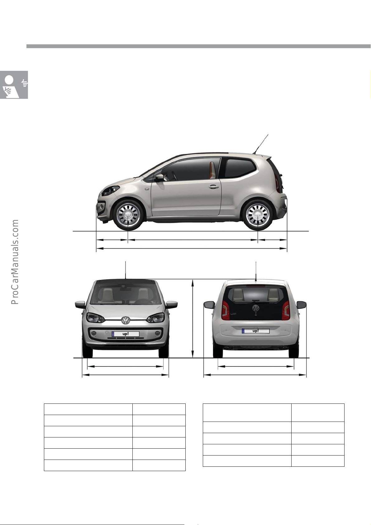
Exterior dimensions and weights
The data refers to a vehicle without driver, with the fuel tank 90% full, standard equipment, a 1.0 l, 44 kW MPI
petrol engine and tyre size 165/70 R14.
Exterior dimensions
Length 3540 mm
Width 1641 mm
Height 1478 mm
Wheelbase 2420 mm
Track width at front 1428 mm
Track width at rear 1424 mm
585 mm 535 mm
1428 mm
1641 mm
2420 mm
3540 mm
1478 mm
1424 mm
1910 mm
Weights/further data
Gross vehicle
weight rating
Kerb weight 854 kg
Turning circle 9.8 m
Tank capacity 35 litres
Drag coefficient 0.32 c
s500_010
1290 kg
d
6
Page 7
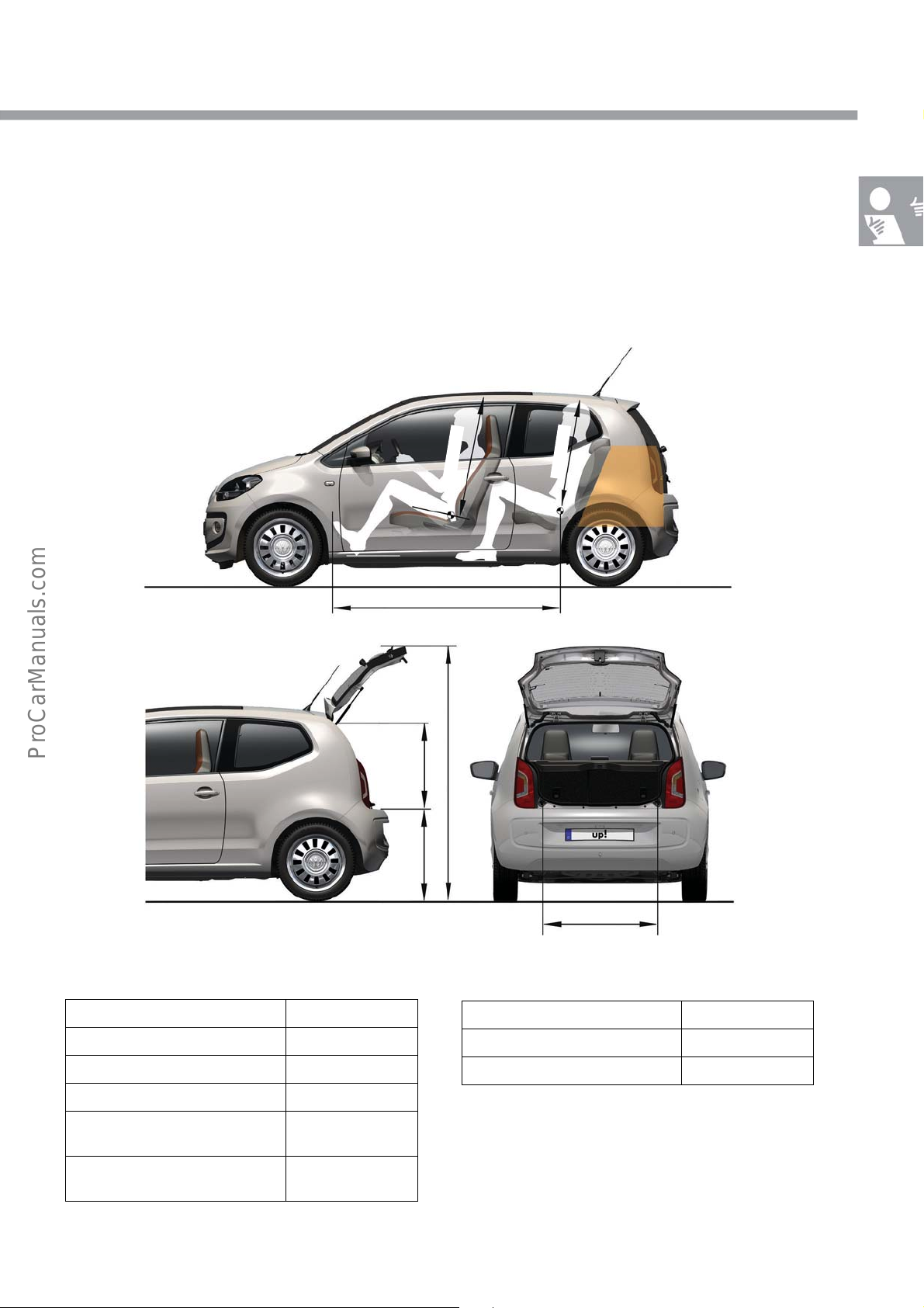
Interior dimensions and volumes
0
0
0
1
1613 mm
570 mm
1990 mm
769 mm
m
m
m
m
7
4
9
Interior dimensions and volumes
Interior length 1613 mm
Luggage compartment volume 251 litres
Height of open rear lid 1990 mm
Height of load sill 769 mm
Height of luggage compartment
aperture
Width of luggage compartment
aperture
570 mm
868 mm
868 mm
s500_012
Front headroom 1000 mm
Headroom – 2nd seat row 947 mm
Knee room – 2nd seat row *
* Sufficient knee room can only be obtained
by reducing the knee room of the first
seat row.
7
Page 8
Body
Body structure
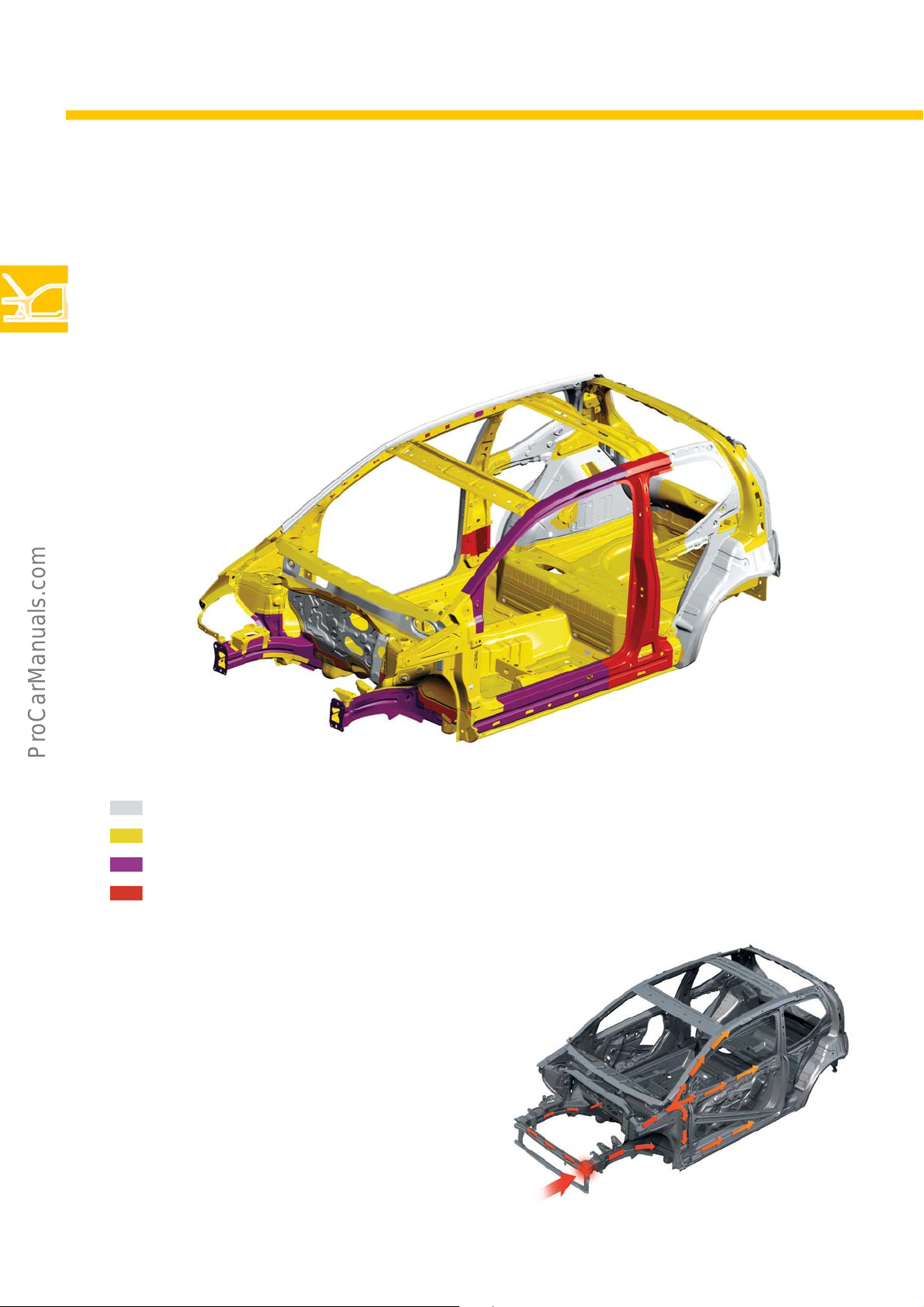
The key focus during development of the body structure was combining high crash safety with a low body weight.
The platform and top are completely new designs. Due to the compact structure, there was no need for a high
proportion of hot formed steels.
Strengths of steel sheets
Soft steel sheet metal <350 MPa
Strengthened steel sheet metal 300-590 MPa
Modern strengthened steel sheet metal 500-980 MPa
Ultra-strengthened hot formed steel sheet metal >1400 MPa
The hot-formed steels increase the rigidity of the
passenger compartment. Additional crash
reinforcement has been installed in the sills of both
doors. In the event of a head-on collision, the forces
are distributed through the entire body via both
longitudinal members.
s500_017
s500_067
8
Page 9
Doors
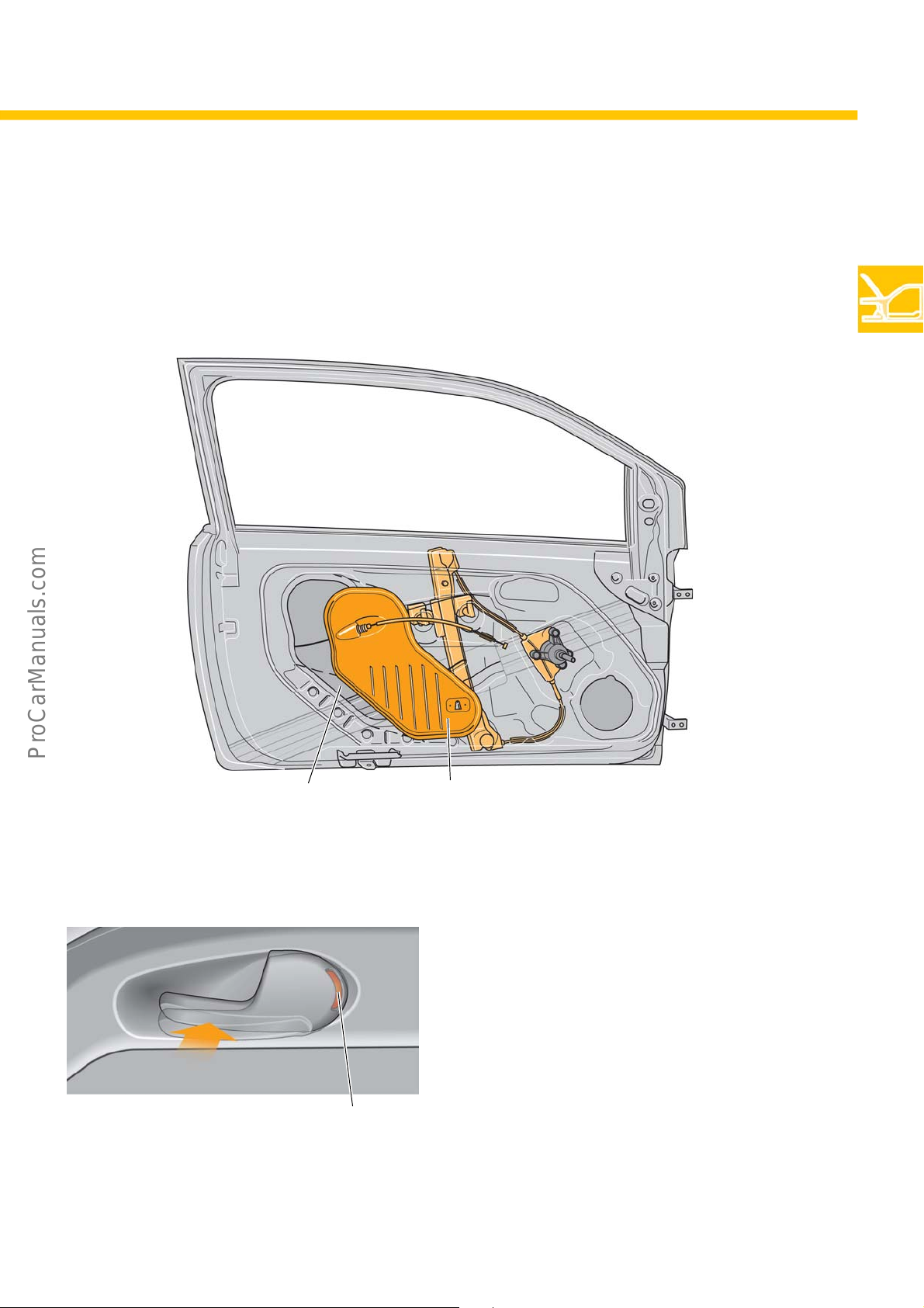
The doors on both the 2-door and 4-door models are assembled in an individual part installation process. The
installation parts for the doors are fitted through the assembly opening. The assembly opening is sealed by a
plastic cover.
Push-pull locking
s500_008
Assembly opening Plastic cover
Push-pull locking is a mechanical locking system.
Pushing the inside door button in the direction of the
arrow locks the door. This is indicated by the red
marking on the back.
Red marking
s500_042
9
Page 10
Body
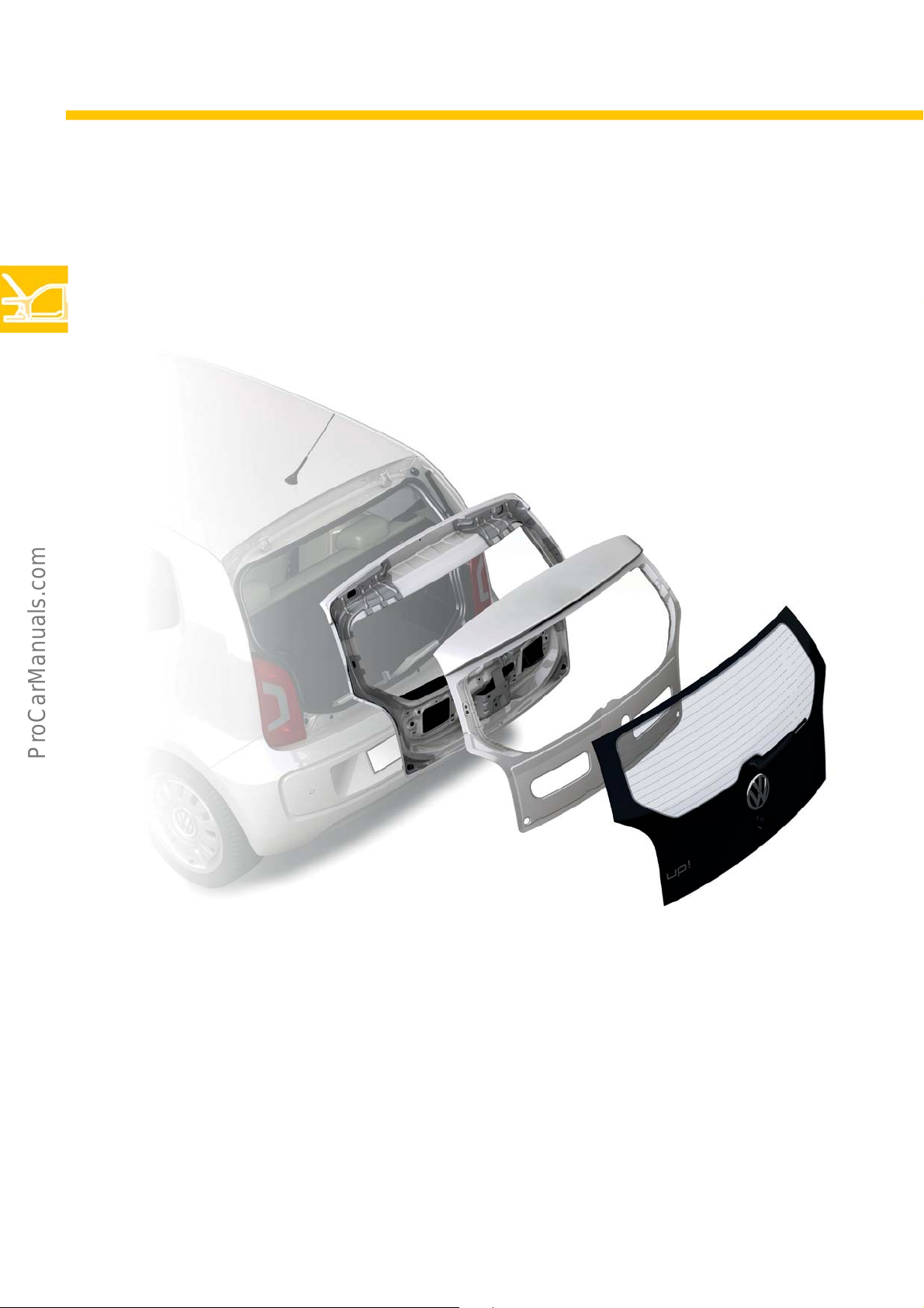
Boot lid
A special feature of the up! is its boot lid in an all-glass finish. It involves creating a conventional structure
comprised of inside, outside and reinforcement parts which are covered by a large glass panel. The panel is
bonded to the boot lid.
s500_065
10
Page 11
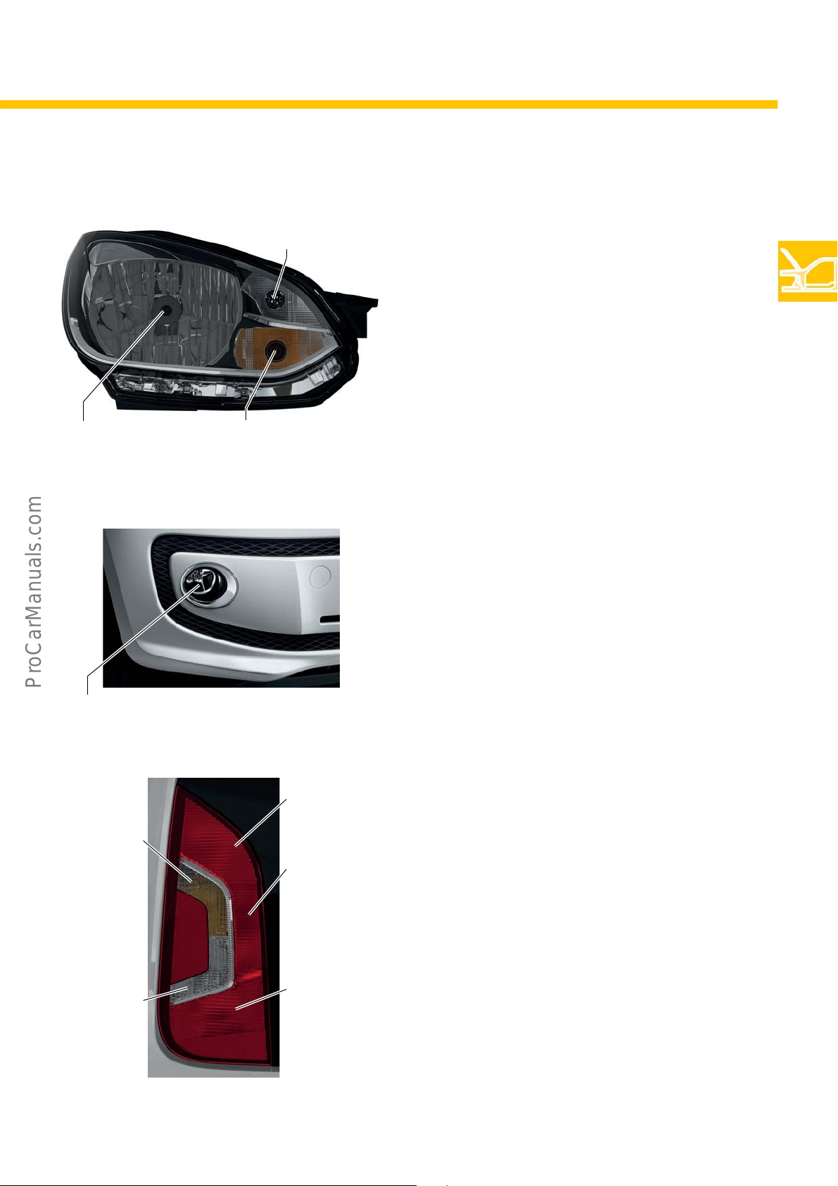
Vehicle lighting
Dipped beam and
main beam
(H4, 55/60 W)
Daytime driving lights
and side lights
(W21, 5 W)
Turn signal lights
(PY, 21 W)
s500_004
Front headlights
The following front lighting functions have been
integrated into the headlights of the up!: dipped
beam, main beam, turn signals, side lights and
daytime driving lights.
The bulbs can be changed
r
emain installed.
while the headlights
Fog lamps
The fog lamps are found in the front spoiler.
Partial disassembly of the wheel housing trim
required to replace the bulbs.
is
Fog lamps (HB4, 55 W)
Turn signal
(RY, 10 W)
Reversing light
(R, 10 W)
s500_069
Tail light and
brake light
(P21, 4 W)
Tail light
(P21, 4 W)
Tail light and
rear fog lamp
(P21, 4 W)
s500_006
Tail lights
The rear lights have been designed as one unit. The
tail light, brake light, turn signal, rear fog light and a
reversing light for both sides are all integrated into
this unit.
The lights have to be removed in order to change the
bulbs. The light cluster
nu
t.
is secured using a central wing
11
Page 12
Body
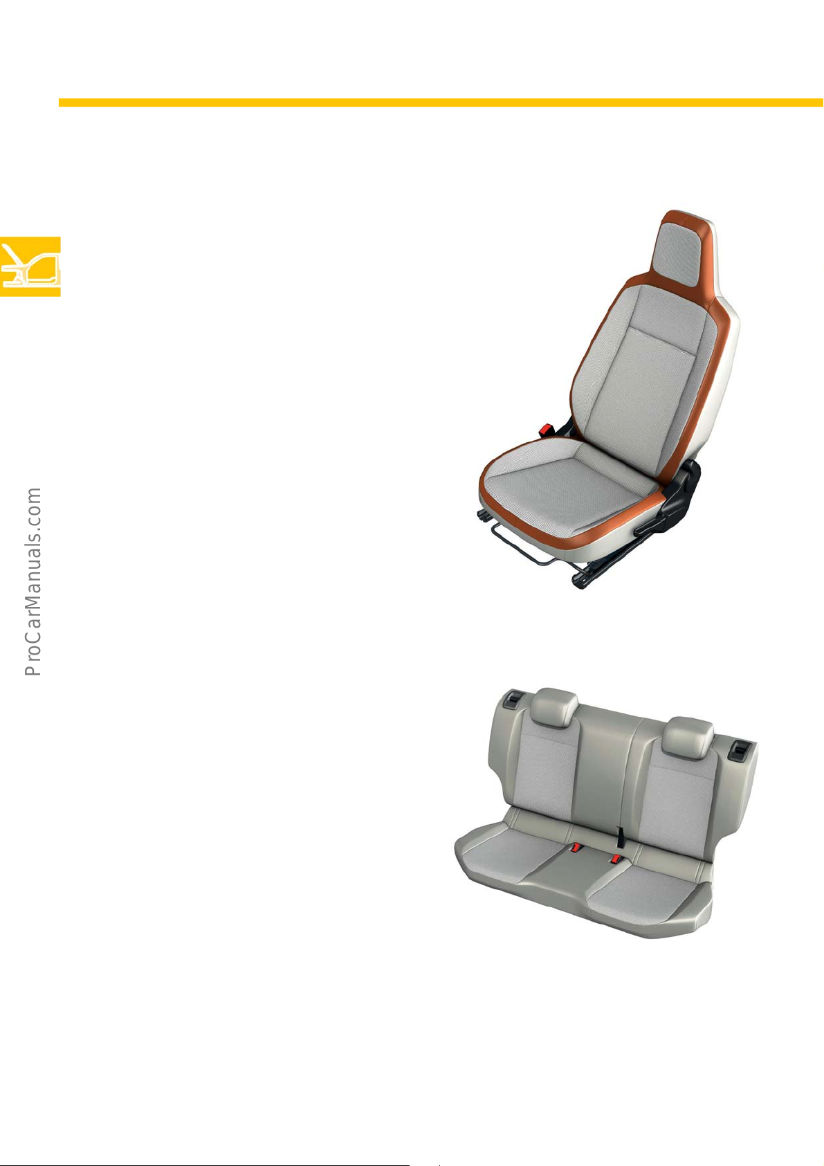
Interior
Front seats
Three types of seat are available in the up! according
to the equipment line featured.
- no Easy entry
- Easy entry
- Easy entry and memory function
The equipment lines “take up!”, “move up!” and “high
a
re distinguished by the different seat covers and
up!”
finishings.
The head restraints are fixed to the front seats in all
uipment lines.
eq
Rear bench seat system
The up! has a one-piece, folding rear seat bench as
standard. With the “move up!” equipment line and
above, this is a two-piece version which can be folded
at a 60:40 ratio.
In conjunction with a variable load floor, both rear
seat systems can be fo
flat surface thanks to a raised pivoting point.
ld
ed down to form a virtually
s500_031
s500_033
12
Page 13
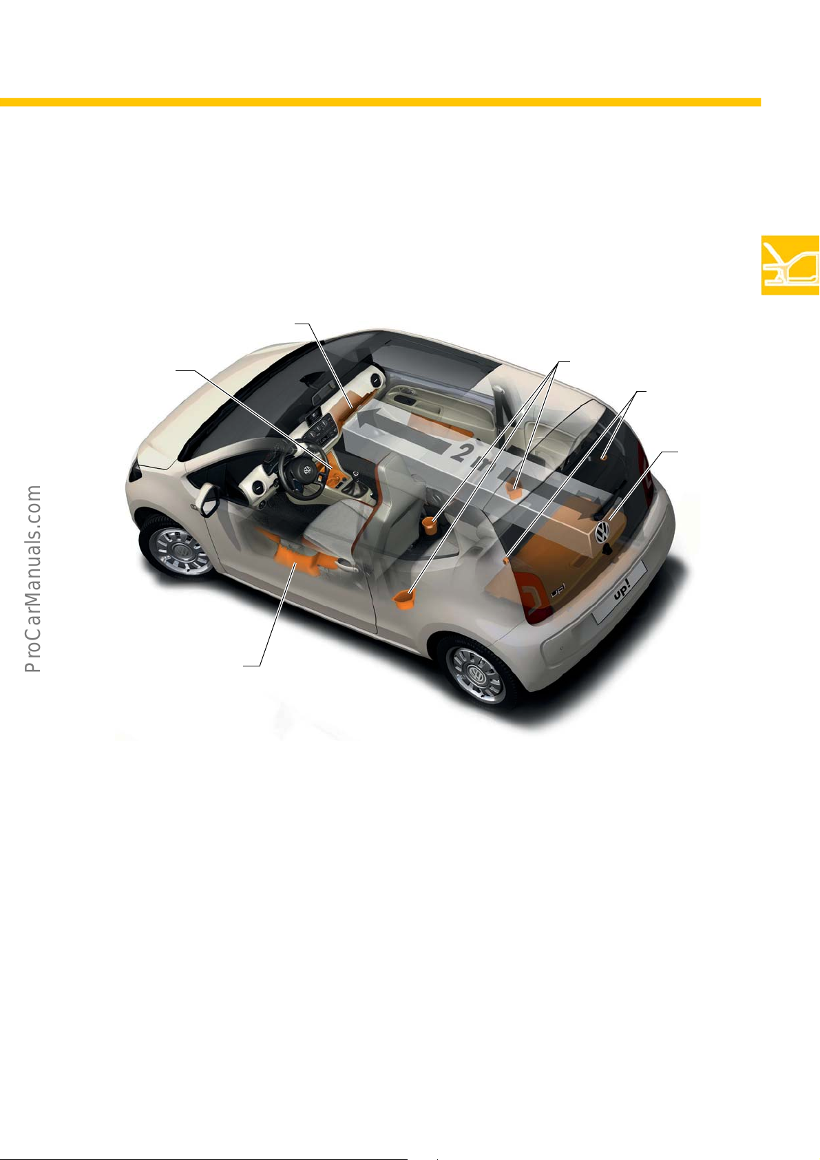
Stowage concept
Numerous multifunctional stowage options are provided in the passenger compartment of the up! to provide the
passengers with enough storage space for items both large and small.
2
1
4
5
6
3
s500_035
Key
1 The centre console has a storage compartment and a drink holder for bottles of up to 0.5 litres;
equipment line “move up!” and above offer fold-out drink holders
2 An open stowage compartment with hooks for bags;
equipment line “move up!” and above offer a closed glove box with a pocket for glasses, a pen and pad holder and a
coin and map holder on the inside
3 A storage compartment and a drink holder for 1.0-litre bottles in the doors
4 Rear drink holder
5 Shopping bag hooks in the luggage compartment
6 Equipment line “move up! ” and above offer variable load floor
13
Page 14
Body
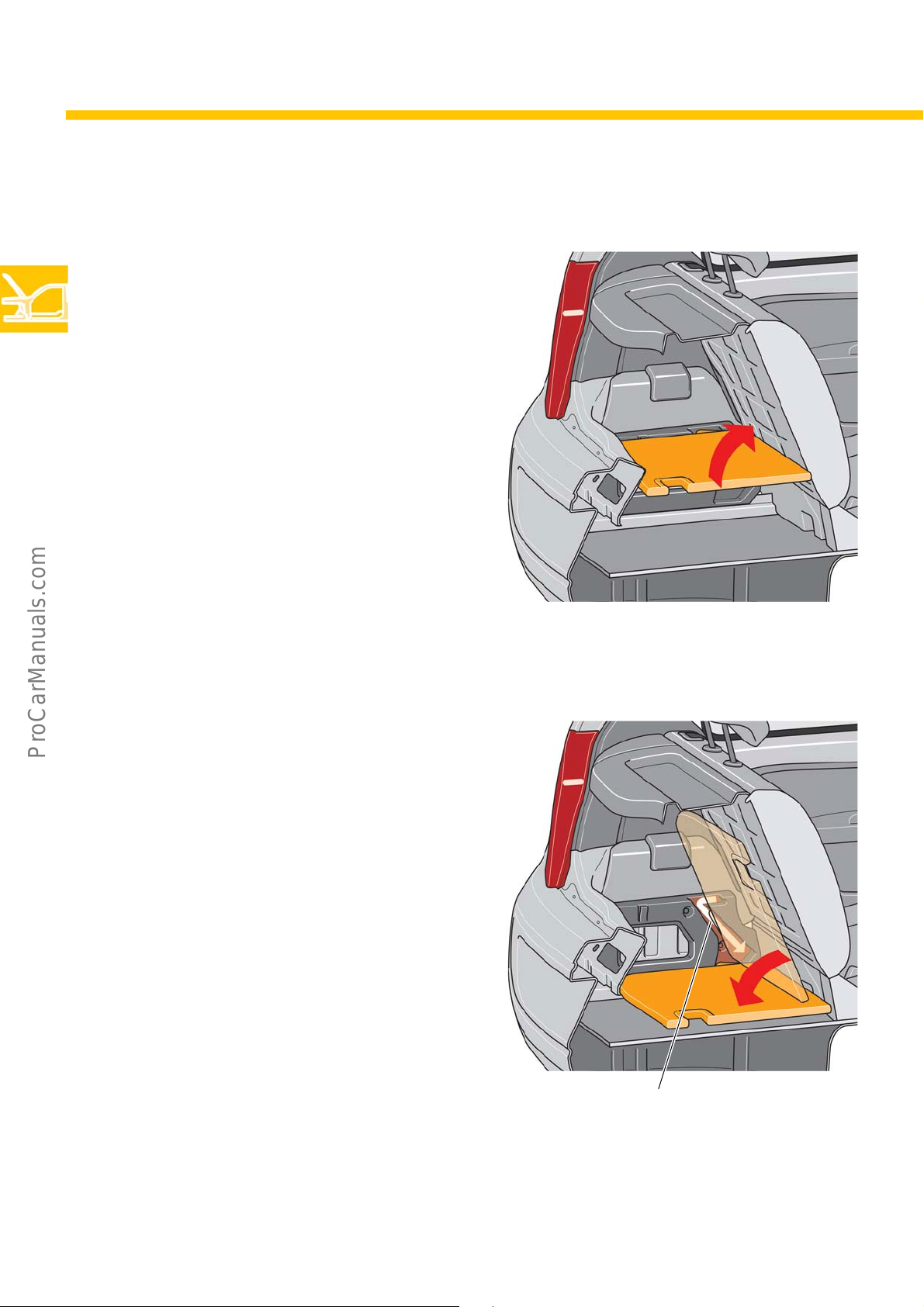
Variable load floor
A variable load floor is available as an option. The
upper position provides a loading surface virtually
level with the loading sill. In addition, there is the
option of stowing various objects below the load
floor.
Upper position
s500_066
The lower position allows the maximum stowage
volume to be exploited.
The Z-shaped guide for the load floor makes
i
ng between the two positions very easy.
chang
Lower position
s500_068
Z-shaped guide
14
Page 15
Safety equipment
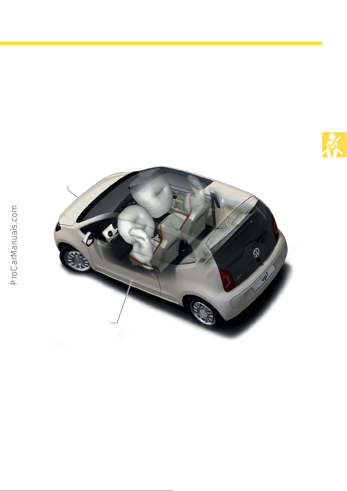
The up! features the following safety equipment as standard:
• Driver airbag
• Front passenger airbag
• Side airbags at front
• Three-point seat belts for front and rear
• Belt pre-tensioners and mechanical belt tension limiters o
•TopTether
Crash sensor in the front
module
n
the front seats
Occupant Protection
Side crash sensor
Belt status display
The standard belt status display in the multifunction
display in the dash panel insert informs the driver
whether the rear passengers have fastened their seat
belts. There is an additional, acoustic seat belt prompt
for the front seats.
s500_039
Crash sensors
In the middle of the front module there is a crash
sensor for early detection of a head-on collision.
There is a side crash sensor located in each door for
detecting a side coll
ision.
15
Page 16
Engines
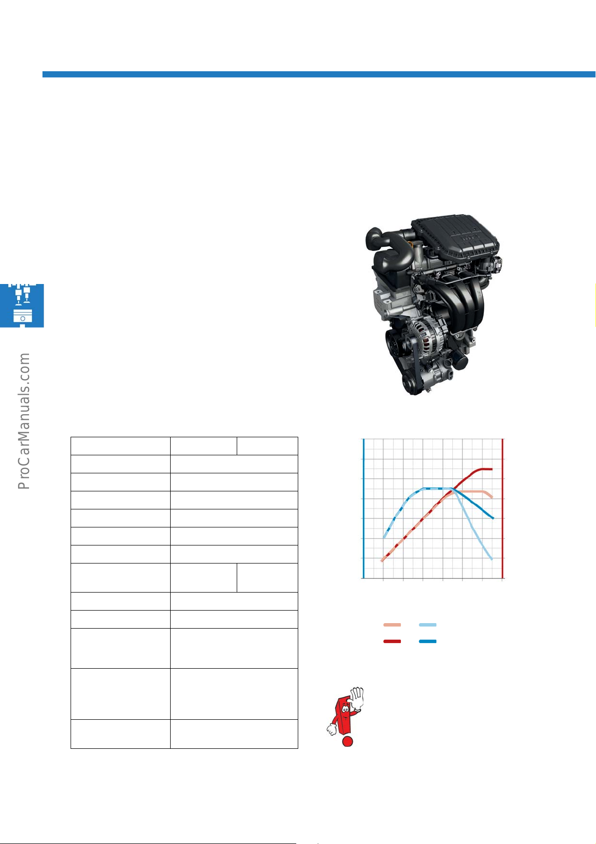
The 1.0 l 44/55 kW MPI engine with intake manifold injection
The 1.0 l 44/55 kW MPI engine is a completely new development, being the first in a new generation of engines.
The engine mechanics are the same for both power variants. The differences in power are achieved with the
software.
Technical features
• Cylinder head with integrated exhaust manifold
• Thermostat housing forms a unit with the coolant
pump
Coolant pump driven by the outlet camshaft via a
•
oot
hed belt
t
• Oil filter installed on the oil sump
• Variable inlet valve timing
(42° crankshaft angle)
Technical data
Engine code CHYA CHYB
Type 3-cylinder inline engine
Displacement 999 cm³
Bore 74.5 mm
Stroke 76.4 mm
Valves per cylinder 4
Compression ratio 10.5:1
Max. output 44 kW at
Max. torque 95 Nm at 3,000-4,300 rpm
Engine management Bosch Motronic ME 17.5.20
Fuel Super unleaded RON 95
55 kW at
5,000 rpm
(Unleaded RON 91 with
reduced performance)
6,200 rpm
Torque and performance diagram
[Nm]
110
100
90
80
70
60
50
1000 3000 5000 7000
s500_040
44 kW
55 kW
s500_015
[kW]
60
50
40
30
20
10
0
[rpm]
16
Exhaust gas aftertreatment
Exhaust emissions
standard
Three-way catalytic converter
with one step-type Lambda
probe upstream and one
downstream
EU5
You will find further information in selfstudy programme no. 508
“1.0 l 40/55 kW MPI engine with intake
manifold injectio
n.”
Page 17
The 0CF manual gearbox
Power Transmission
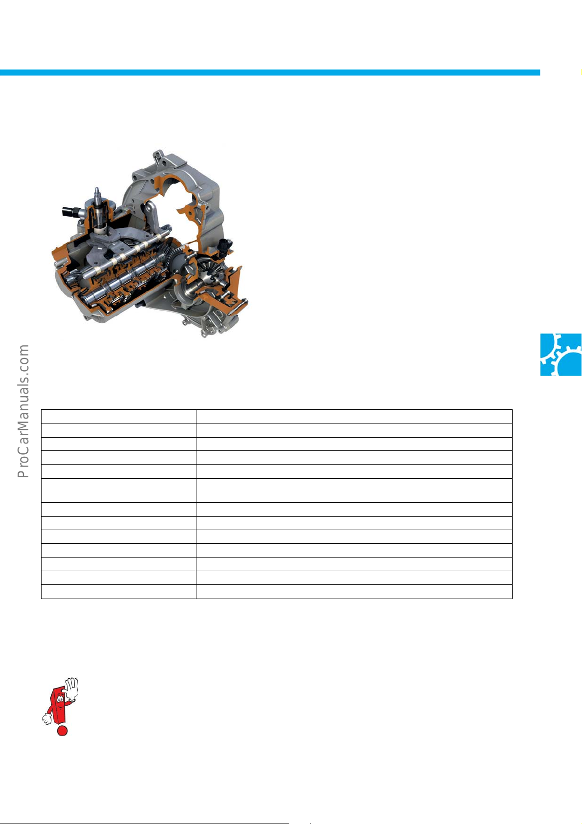
The market launch of the up! coincides with the
introduction of a new Volkswagen 5-speed manual
gearbox. This 0CF manual gearbox is characterised
by its compact, lightweight design.
The development goals successfully achieved
•
greater efficiency
• a weight reduction achieved by optimising all
gearbox components
• a streamlined design
• streamlining of the assembly process
s500_014
Technical data
Gearbox designation 0CF
Gearbox type 5-speed manual gearbox; a two-shaft gearbox with additional reverse
Installation position Front/transverse installation
Structural length/width 356 mm/462 mm
Max. input torque 120 Nm
Material used for gearbox and clutch
housing
Gear oil SAE 75 W as per TL 52527-A
Initial fill/oil change quantity 1.2 l/1.1 l
Weight 26.7 kg with oil
Final drive ratio 74:19 (44 kW); 75:18 (55 kW)
Gear pairs Identical for 44 kW and 55 kW
Gear range 4.57
Reaches top speed in 4th gear
Aluminium
include:
gear shaft.
Further information on the design and functions can be found in self-study programme no. 509
“The 0CF manual gearbox”.
17
Page 18
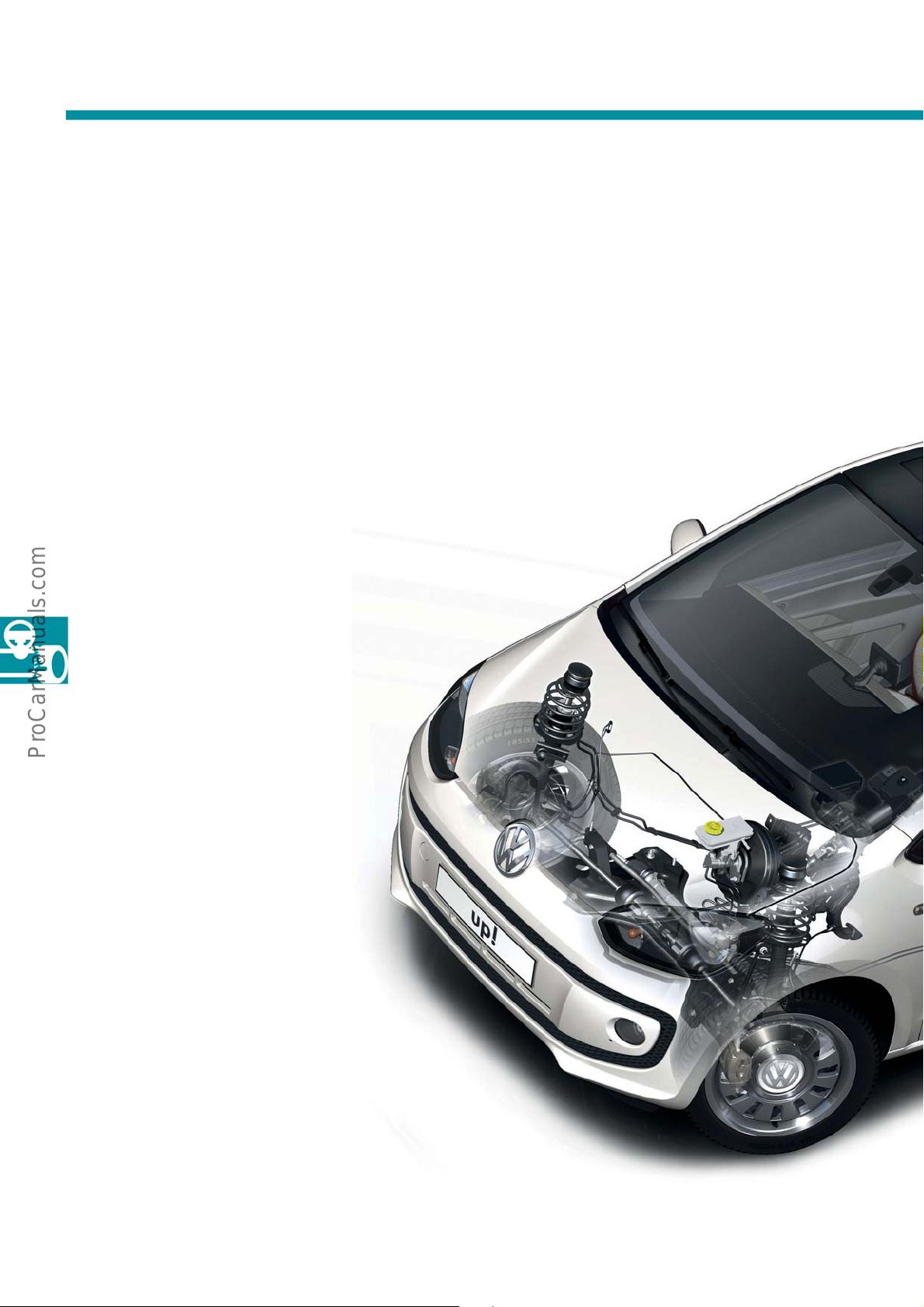
Running Gear
Overview of running gear
The overview presents the most important standard and optional running gear equipment for the up! The up! can
be equipped with normal suspension or sports suspension.
• Disc brake, front
• ESP/ABS TRW 460
• Electromechanical power steering
C-EPS (column electric p
steering)
• McPherson strut front suspension
ower
18
•9" brake servo
for left-hand drive vehicles;
8.5" brake servo
for right-hand drive vehicles
Page 19
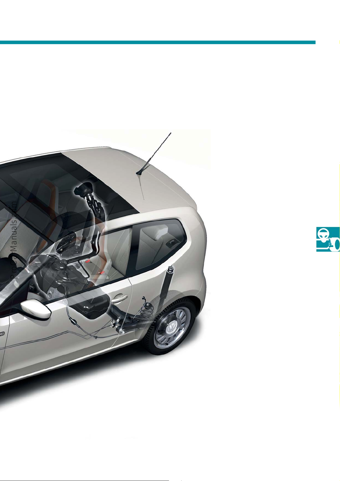
• City emergency braking function
(optional)
• Torsion beam rear axle
s500_021
• Tyre mobility set (standard)
• Drum brake, rear
19
Page 20
Running Gear
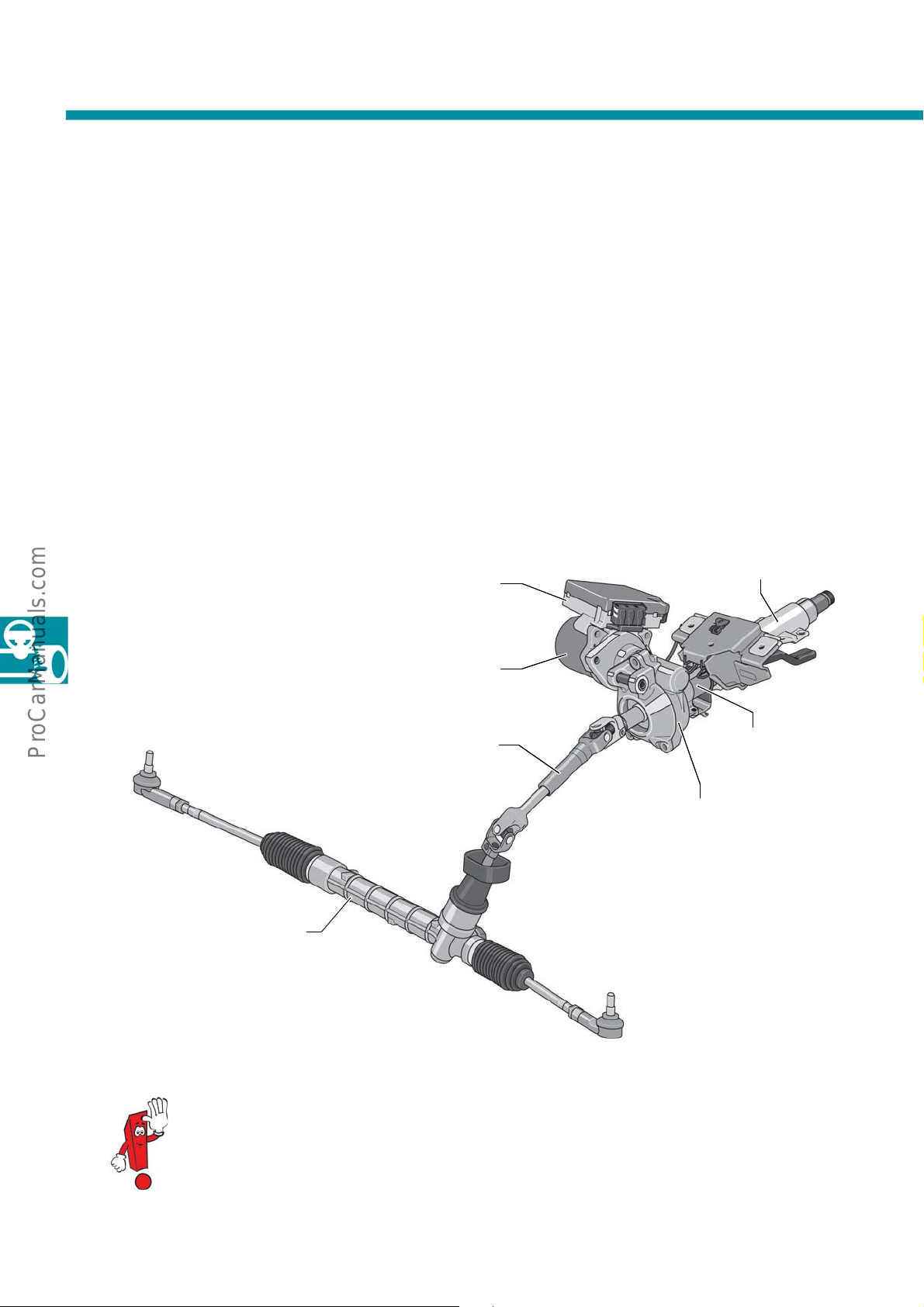
The electromechanical power steering system
The electromechanical power steering system provides steering assistance using an electric motor on the steering
column. The electromechanical power steering system is compatible with every engine/gearbox combination.
The steering is comprised of the following components:
- Steering wheel
- Steering column switch
- Steering column
- Steering torque sender G269
- Worm gear mechanism
Power steering
control unit J500
Electromechanical power
steering motor V187
Universal joint shaft
- Electromechanical power steering engine V187
- Power steering control unit J500
- Universal joint shaft
- Mechanical steering gear
Steering column with height adjustment
Steering torque sender
G269
Worm gear mechanism
20
Mechanical
steering gear
s500_020
Further information on the design and functions of the electromechanical power steering system can be
found in self-study program no. 447 “The Polo 2011”.
Page 21
The city emergency braking function
This driver assistance function is being implemented in the compact vehicle segment at Volkswagen for the first
time in the up! In the up!, the city emergency braking function is a self-contained system.
If a collision with a vehicle travelling in the same dir
not reacted, the city emergency braking function responds at speeds below 30 km/h and, when required,
matically initiates a braking procedure. Ideally, this function can prevent a front-end collision or help to
auto
minimise accident damage. The signals required for the city emergency braking function are relayed by the
emergency braking function sensor unit J939.
ection, or a stationary object, is imminent and the driver has
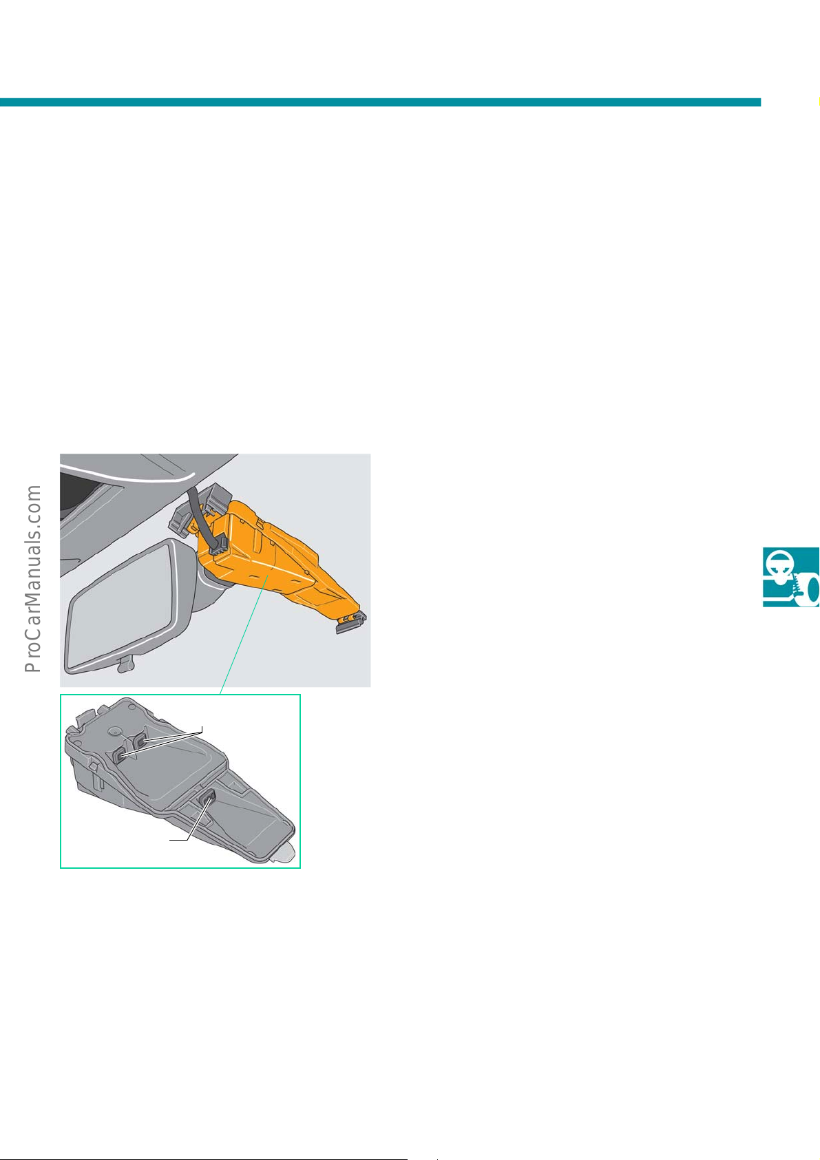
Emergency braking function sensor unit J939
The emergency braking function sensor unit J939 is a
laser sensor. This is also referred to as a CV sensor
(closing velocity). The sensor unit has been integrated
into the mirror base and features the following
characteristics:
- It transmits signals using infrared light with a
h
of 905 nanometres (which cannot be
Receiver lenses
wavelengt
detected by the human eye).
- It has an aperture angle of 27° horizontal
and 12° vertical.
- It has a range of 10 metres.
s500_060
s500_054
Sender lens
Function
The emergency braking function sensor unit calculates
h
e distance, speed, and direction of an approaching
t
object in the direction of travel.
If the laser signals emitted encounter an object, then
re
they are
flected.
The emergency braking function sensor unit is
comprises of a sender and a receiver unit. The sender
lens has three beams. The receiver unit is comprised
of two lenses.
A decoder in the sensor unit calculates the distance
sed on the time between in the outgoing and
ba
incoming laser signals.
21
Page 22
Running Gear
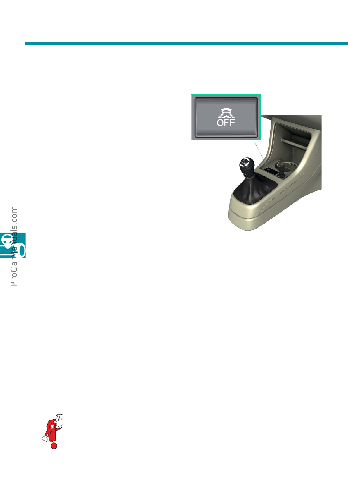
Button for emergency braking function E773
The button for the emergency braking function E773
is located in the centre console above the gear
selector.
The city emergency braking function remains active
once the engi
activated and deactivated by pressing the button.
ne has been started. The function is
s500_056
Usage conditions
• The city emergency braking function responds at speeds not exceeding 30 km/h.
• It monitors the traffic travelling in front of the vehicle
• The city emergency braking function reacts to vehicles moving in the sa
System limitations
• The city emergency braking function does not warn the driver in advance.
• The city emergency braking function does not react to vehicles crossing or ap
direction, nor does it react to road users with weak reflections (such as pedestrians).
s500_058
and any obstacles within a range of 10 metres.
me direction, braking or stopping.
proaching from the other
22
The city emergency braking function cannot guarantee that it will prevent accidents.
Page 23
System functions
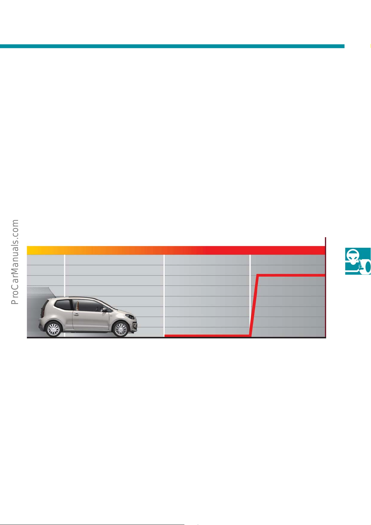
The emergency braking function sensor unit monitors the area in front of the vehicle with a range of up to ten
metres.
Should the time interval to an obstacle decrease so quickly that a front-end collision is imminent, the brake system
is prefilled and the Hydrauli
brakes respond immediately when the driver depresses the brake pedal.
c Brake Assist system (HBA) switches to “increased sensitivity”. This means that the
If the driver does not brake, or brakes to
friction provided by the road surface, the condition of the brakes, and the tyres.
The following diagram shows the sequence of
brake, or brakes too little.
Risk of collision
o little, the vehicle can brake at a rate of up to 10 m/s 2 depending on the
events when a risk of collision is detected and the driver does not
Collision
at its highesthighslightly higher
s500_064
Prefill,
switchover to HBA
Braking of up to 10 m/s
2
23
Page 24
Heating and Air Conditioning
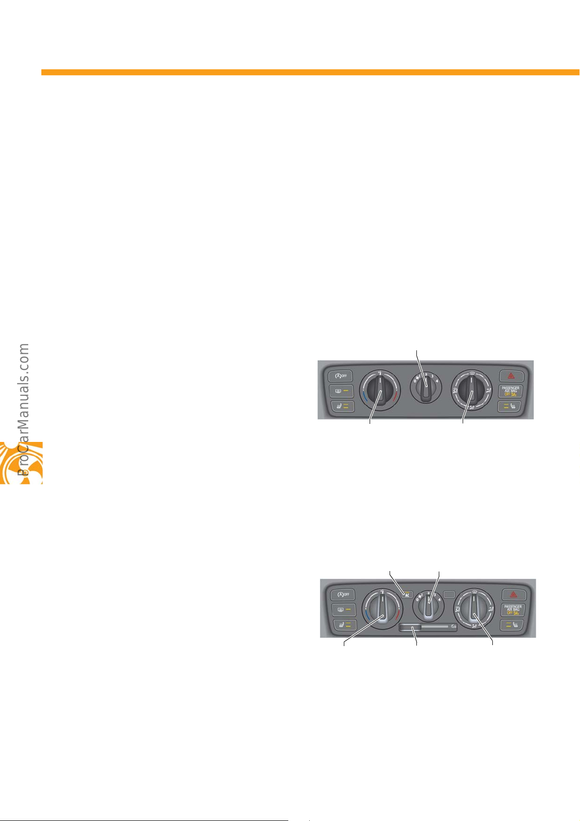
The up! features a choice of two different heating/air-conditioning concepts:
• The manual heating and ventilation system
• The manual heating and air conditioning system
Each variant has its own operating unit. All contr
integrated into one operating unit. The up! is equipped with a manual heating and ventilation system as a standard
feature.
The manual heating and ventilation system
The temperature flap and the flaps for air distribution
are adjusted using rotary knobs on the operating unit.
Each adjustment made is relayed to the flap
mechanism on the heating and ventilation system via
a flexible shaft.
ols used to adjust the temperature and ventilation have been
Rotary knob for fresh air
blower
Rotary knob for
temperature selection
Rotary knob for air
distribution
s500_048
24
The manual heating and air conditioning system
The air conditioner is equipped with one flexible shaft
each for setting the temperature and activating the
air flaps. The temperature and air distribution are set
manually, allowing manual adjustment when needed.
The manual air conditioner utilises an internally
rolled air conditioner compressor with magnetic
t
con
clutch.
AC button with
feedback LED
Rotary knob for
temperature
selection
Rotary knob for fresh air
blower
Slide for
recirculated
air mode
Rotary knob for
air distribution
s500_046
Page 25
Switching on the air conditioning system
The air conditioner is switched on and off using the AC button. Pressing this button relays the command “Air
conditioner on” to the engine control unit. This is achieved by applying a voltage of 7.5 V. When deactivated using
the AC button, the comma
At air blower level 0, no AC command is relayed.
nd is revoked (voltage level is then 0 V).
Activating the air recirculation flap
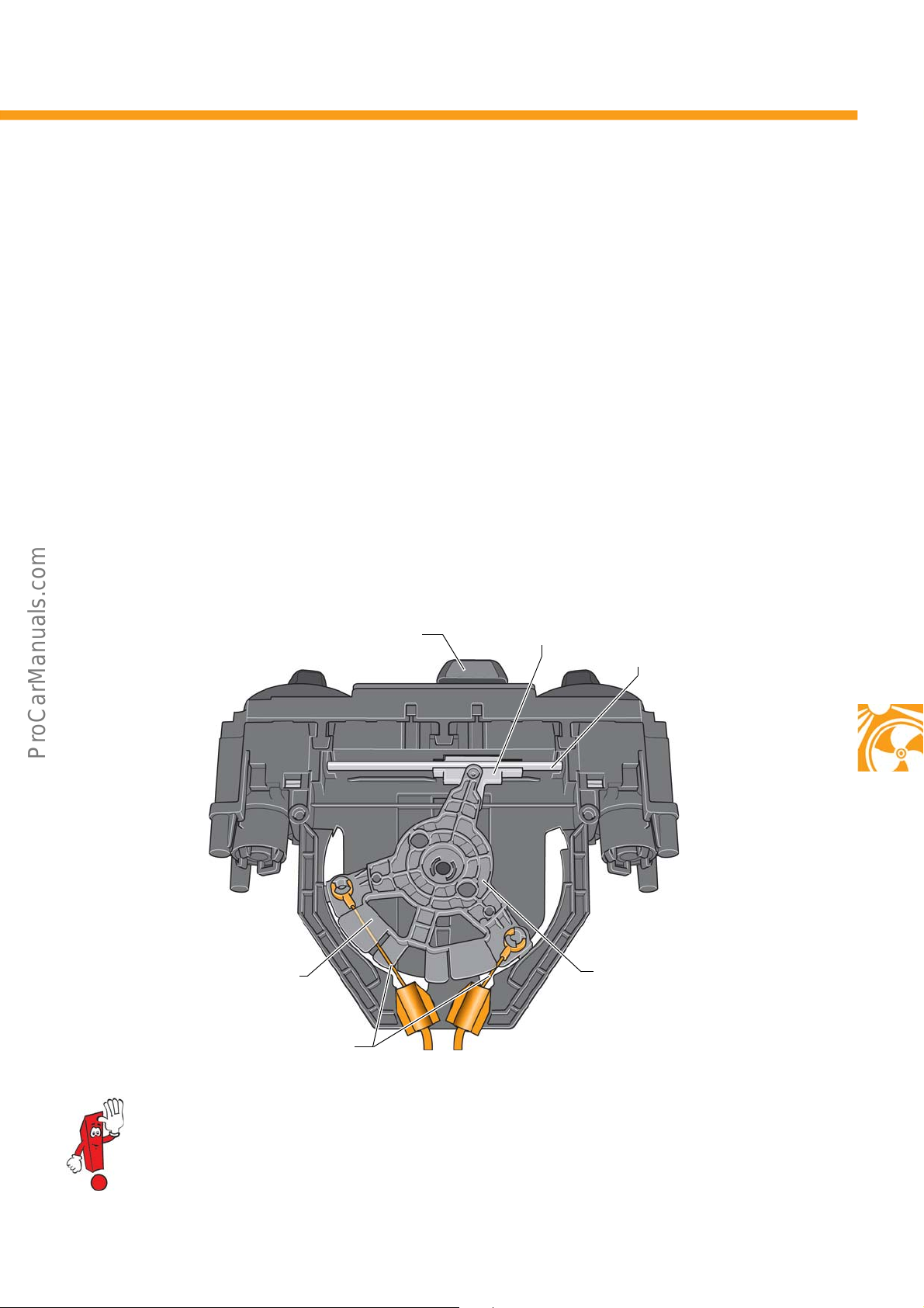
The air recirculation flap is activated using a slide on the control panel. A special mechanism, comprised of a rail,
sliding carriage and rotating Bowden cable anchorage, transmits the movement of the slide to the two Bowden
cables with multiple guides. The guide is required to prevent the steel wire from bending. The slide engages
mechanically at the end stops to secure the positions “Air recirculation flap open” and “Air recirculation flap
closed”.
Slide on control panel
Guide
Bowden cables
Sliding carriage
Rail
Rotating Bowden cable
anchorage
s500_052
You will find further information on the heating and ventilation system as well as the heating and air
conditioning system in self-study programme no. 263 “The Polo 2002”
25
Page 26
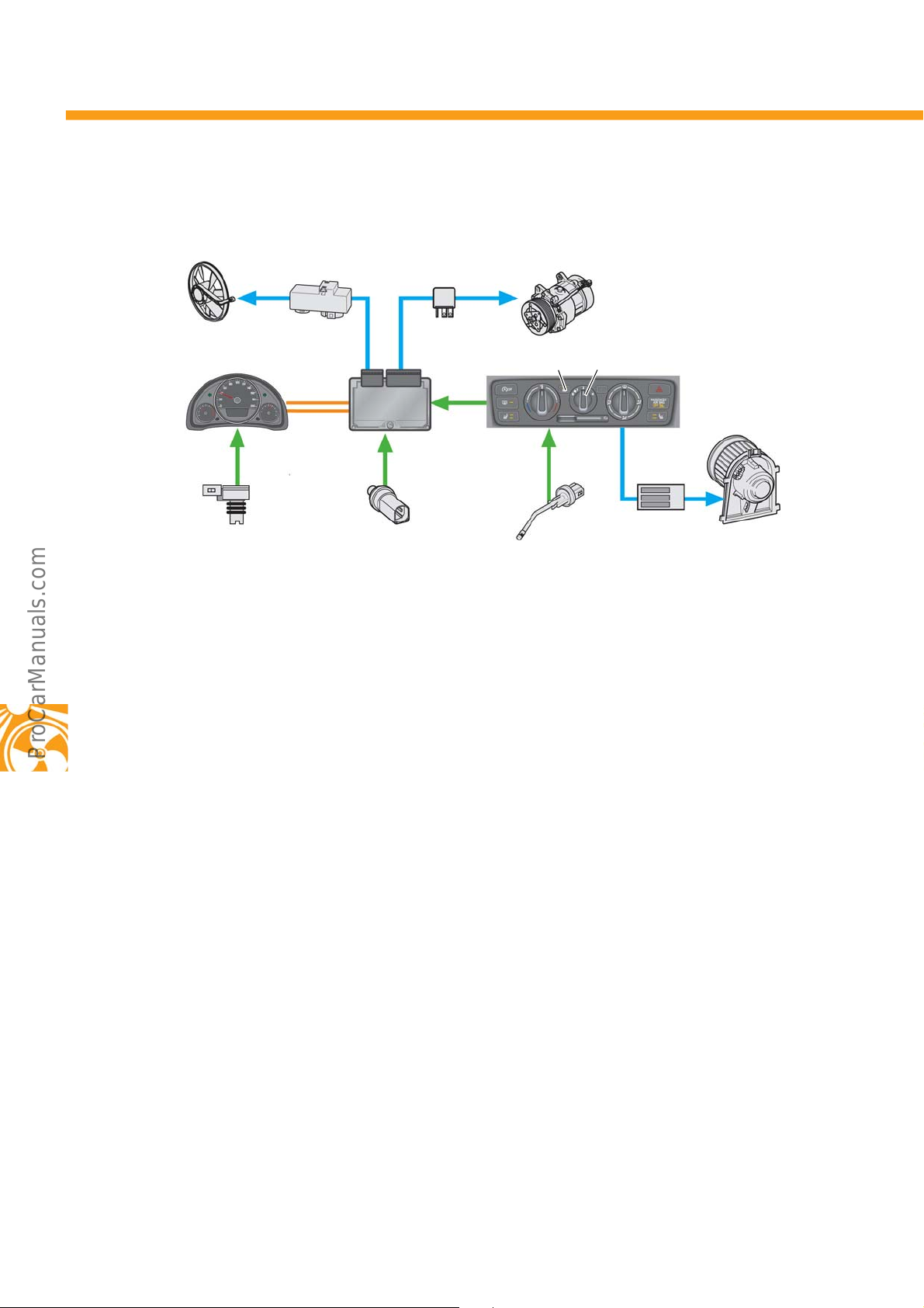
Heating and Air Conditioning
System overview
V7
J298
G17
Key
E9 Fresh air blower switch
E30 Air conditioning system switch
G17 Ambient temperature sender
G65 High pressure sender
G308 Evaporator temperature sensor
J32 Air conditioning system relay
J285 Control unit in dash panel insert
J293 Radiator fan control unit
J293
J623
G65
J32
V454
E9E30
J301
G308
J301 Air conditioning system control unit
J623 Engine control unit
N24 Fresh air blower series resistor with
overheating fuse
V2 Fresh air blower
V7 Radiator fan
V454 Air-conditioning compressor
N24
V2
s500_032
26
Page 27
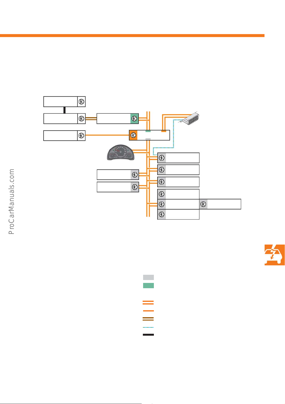
Electrical System
Vehicle electrical system
The following diagram provides an overview of the network formed by the control units in the up! It uses the
network of a fully equipped vehicle with all options as an example.
J982
J983
J245
s500_070
Key
G85 Steering angle sender
G269 Steering torque sender
G751 Rotor position sender for active steering motor
J104 ABS/ESP control unit
J234 Airbag control unit
J245 Sliding sunroof adjustment control unit
J285 Control unit in dash panel insert
J362 Immobiliser control unit
J446 Parking aid control unit
J500 Power steering control unit
J519 Onboard supply control unit
J533 Data bus diagnostic interface
J623 Engine control unit
J939 Emergency braking function sensor unit
J982 Portable navigation and infotainment system
J983 Interface for portable navigation and infotainment
sy
st
em
R
J285/J362
J446
J104
T16
J519/J533
J623
J234
J939
G269
J500
G751
R Radio
T16 Connector, 16-pin (diagnostics connection)
* The G85 is only integrated in the E595 steering
col
umn combination switch in vehicles with EPS.
Drive train CAN data bus
Convenience CAN data bus
LIN data bus
CAN data bus line
LIN data bus line
Unidirectional LIN data bus line
K-line
Mechanical coupling
G85*
27
Page 28
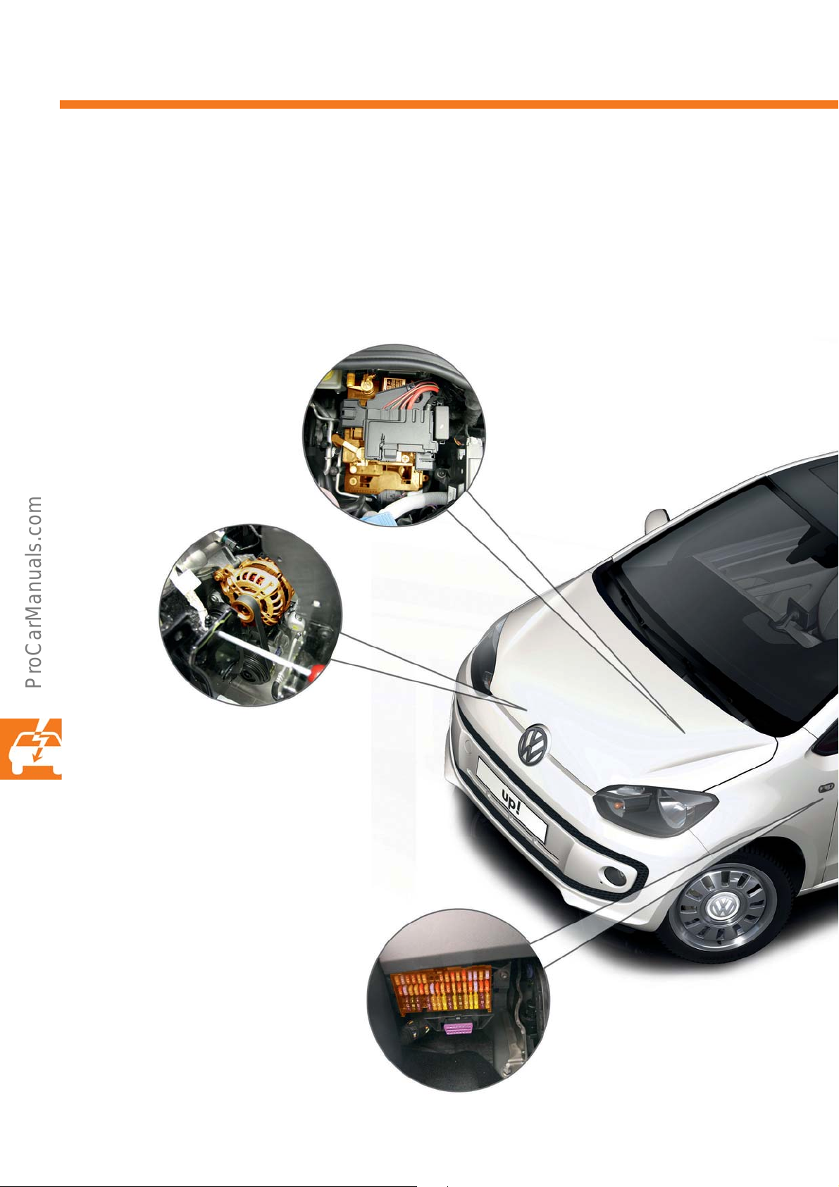
Electrical System
Installation points in the vehicle electrical system
• Battery, on the left in the engine compartment
A 36 Ah/175 A battery with a charge status display is
installed a
220 A battery with a charge status display is installed
in vehicles whi
countries (H4 format).
s standard equipment (H3 format).A 44 Ah/
ch are sold in the so-cal
led cold
•Alternator, on the right in the engine
compartment
A 90 Ah alternator is installed in vehicles with
a heating and ventilation system.
If the vehicle is equipped with a heating and
air-conditioning system, a 110 Ah alternator is
installed.
•Fuse box,
at the bottom left on the driver's
side of the passenger compartment
28
Page 29
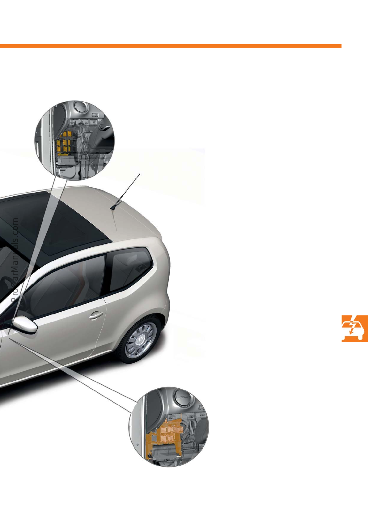
• J519 onboard supply control unit with an
integrated diagnostics interface for J533
data bus, behind the relay carrier
s500_025
• Relay carrier,
on the driver's side of the
passenger compartment, behind
the left-hand dash panel
29
Page 30
Electrical System
Dash panel insert
Depending on the equipment, the dash panel insert is available in the following versions.
• Lowline
• Highline
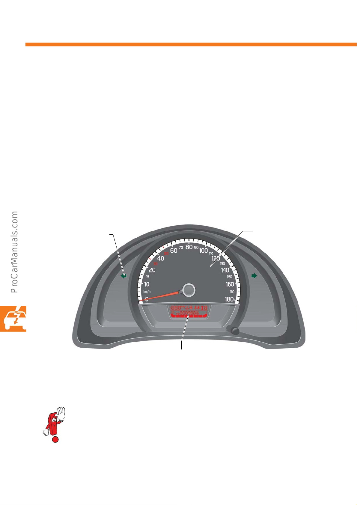
Lowline version
The single-tube dash panel insert consists of a large round analogue instrument and a multi-line digital display.
The speed is displayed on the round analogue instrument. The display shows the tank fill level, the coolant
temperature, the outside temperature, the seat belt prompt for the front seats and the belt status display for
passengers in the rear. Gear shift recommendations and a gear display are also shown. Switching over between
the trip counter and total mileage remains possible. The display colour is red.
Turn signal indicator lamp
Display
Speed display
s500_116
30
The dash panel insert used in the lowline version calculates all multifunction data even if it cannot be
displayed. The data is sent to the J982 portable navigation and infotainment system and displayed by
this system if it is installed.
Page 31
Highline version
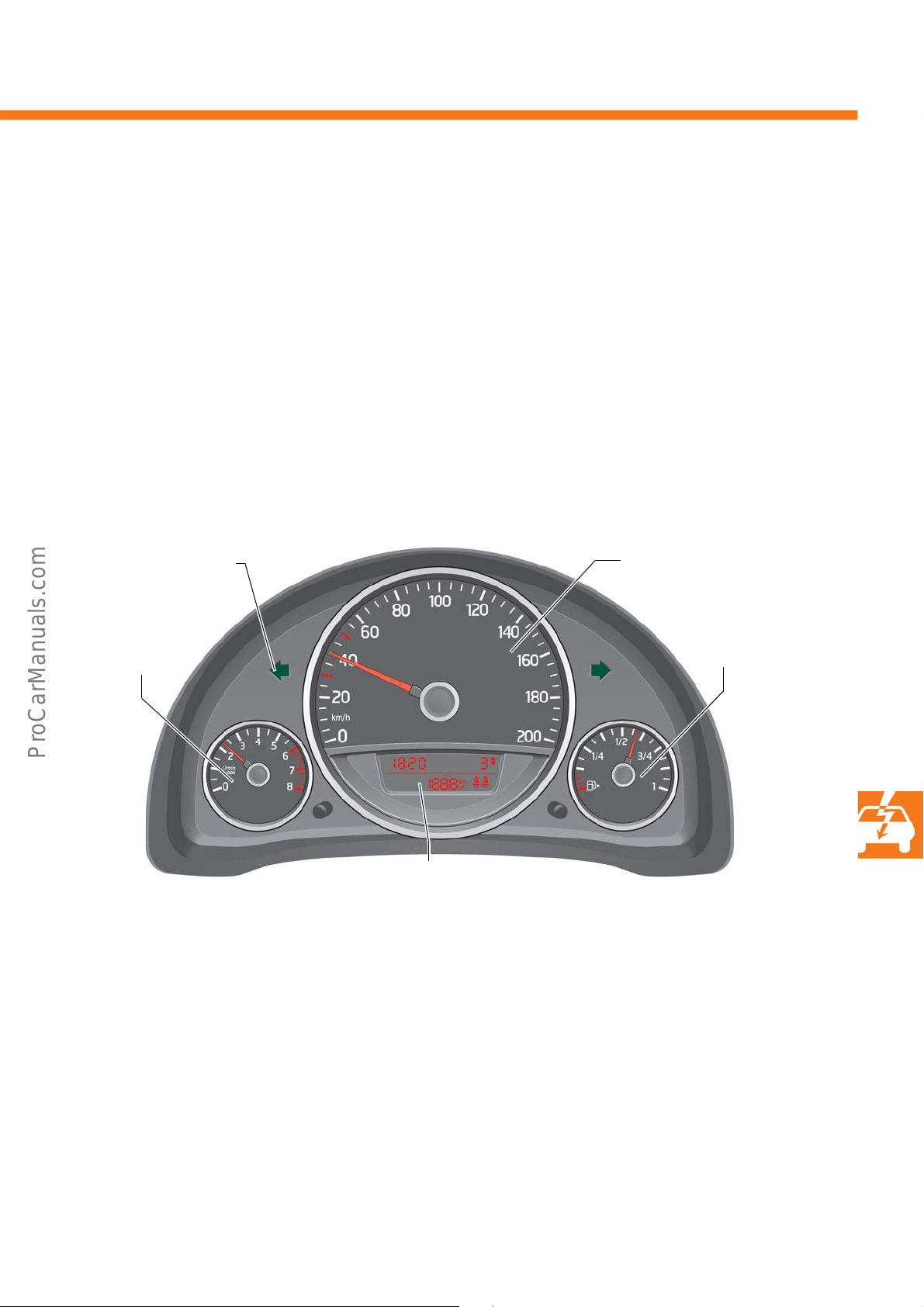
There is a large round analogue instrument at the top centre of the 3-tube dash panel insert and one smaller round
analogue instrument on the left and right. A multi-line multifunction display is installed within the centre tube. The
speed, tank fill level and the engine speed are displayed by the round analogue instruments. The display shows the
coolant temperature, the outside temperature, the seat belt prompt for the front seats and the belt status display for
passengers in the rear. Gear shift recommendations and a gear display are also shown. Switching over between
the trip counter and total mileage is possible. Information on the functional state of the CV sensor is also available.
The display colour is red.
Turn signal indicator lamp
Engine speed
display
Display
The multifunction display (MFD) actuates the functions in the following order:
-Temperature
-Driving time
- Current consumption
- Average consumption
- Range indicator
-Distance
- Average speed
- Speed warning
s
For the memory-related sub-functions, such a
memory level 1 or 2 is also displayed.
driving time, distance, average speed and average consumption,
Speed display
Tank fill level display
s500_112
31
Page 32

Convenience Electronics
Onboard supply control unit
Further enhancements have been made to the J519 onboard supply control unit for the up! and new functions
have been added. It also takes on the functions of the central control unit for the J393 convenience system as well
as the diagnostic interface functions for the J533 data bus. The diagnostic interface for the J533 data bus is not a
separate, self-contained control unit, but has been fully integrated into the onboard supply control unit.
The onboard supply control unit is insta
lled undernea
73-pin connectors.
Functions
The scope of functions depends on the equipment. The higher equipment levels are supplemented with the
functions listed.
th the dash panel at the left and is connected using two
Equipment Functionalities
Basic+ Control of the fuel feed of the electric fuel pump
Medium++ Central locking
Load management
Actuation of driver's door contact
Dimming information sent to the CAN data bus
Actuation of windscreen wipers; levels I, II and intermittent
CV sensor button
Actuation of hazard lights, emergency brake hazard lights, brake lights and turn signals
Actuation of signalling horn
Terminal detection, terminal 15, S-contact
Actuation of rear window heating (max. duty cycle of 450 s)
Actuation of tailgate authorisation without
Actuation of interior light (terminal 30)
Drive train CAN data bus
Diagnosis CAN data bus
Actuation of door contacts
Actuation of convenience rear wiper
Actuation of exterior mirror heating
Seat heating authorisation
Convenience CAN data bus
Radio remote control (433/315 MHz)
Actuation of tailgate authorisation
central locking
32
High+ Starter repeat lock
Reversing lights (dimmed)
Cruise-control system
LIN data bus roof (tilting panorama sunroof)
Page 33
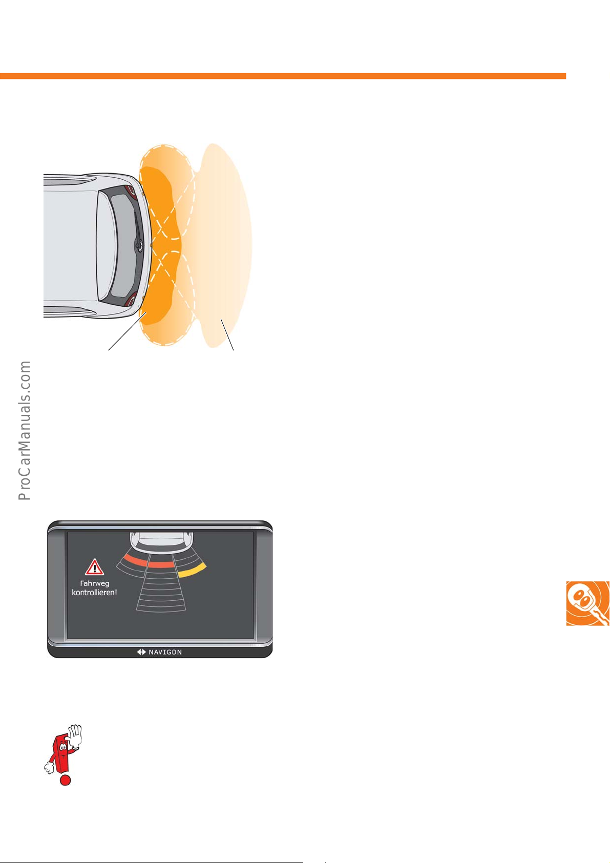
Parking aid
s500_030
Continuous tone
Intermittent tone with distance-
related frequency
An optional parking aid, also referred to as a parking
distance control (PDC) is available for the up! to help
with reverse parking. In the up!, a 3-channel PDC
system will be employed for the first time by
Volkswagen. This involves installing three ultrasonic
sensors around the bumper in the rear of the vehicle.
The parking distance warning system therefore only
detects objects that are behind the vehicle.
ar left of the luggage
The control unit is found in th
compartment. The warning buzzer is installed in the
left C-pillar. The system is activated as soon as the the
ignition is switched on and the reverse gear engaged.
The distance warning (distance-related intermittent
tone) is initiated at an interval of 60 cm (side sensors)
or below, and an interval of 150 cm (middle sensor)
or below. At a distance of less than 30 cm, a
continuous signal tone is emitted. Only the warning
about the obstacle near the sensor closest is given.
e re
Optical parking system (OPS)
red = continuous tone
yellow = intermittent tone
The display contents shown correspond to the infotainment system with the German system setting and
serve merely as an example. Please refer to the corresponding operating manuals for the respective
text content displayed in other national languages.
s500_036
If the vehicle features the optional navigation and
infotainment system “maps + more”, the driver is also
given visual support. The OPS functions by having the
parking aid control unit evaluate the distance
information according to sector and transmitting it to
the navigation and infotainment system
“maps + more”. Not only does this allow the opti
parki
ng system to indicate obstacles behind the
vehicle, but also indicate its relative position to the
vehicle in the scanning area.
cal
33
Page 34
Convenience Electronics
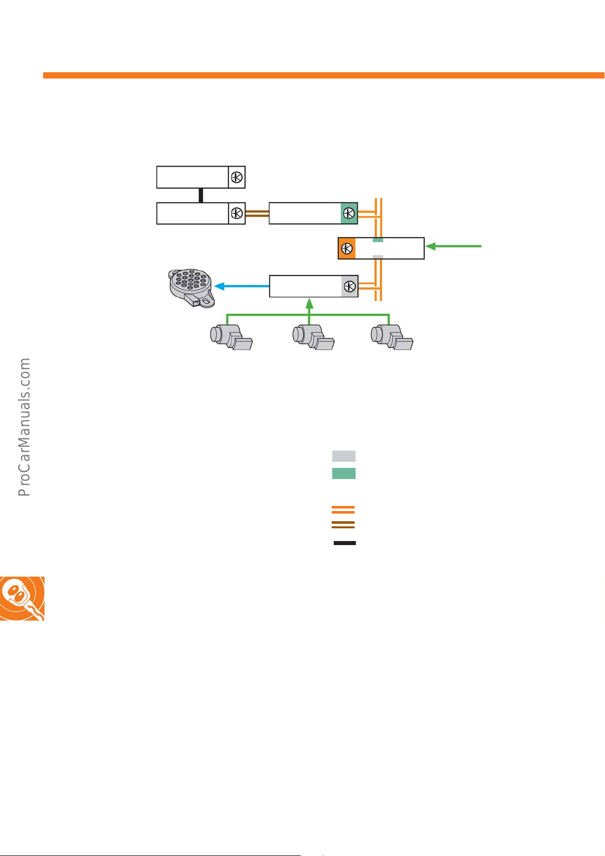
Networking
J982
Key
G203 Rear left parking aid sender
G796 Rear centre parking aid sender
G206 Rear right parking aid sender
H15 Parking aid warning buzzer
J446 Control unit for parking aid
J519 Onboard supply control unit
J533 Data bus diagnostic interface
J982 Portable navigation and infotainment system
J983 Interface for portable navigation and infotainment
sy
stem
R Radio
H15
J983
G203
R
J446
G796
Reversing light
switch
J519/J533
G206
s500_114
Drive train CAN data bus
Convenience CAN data bus
LIN data bus
CAN data bus line
Unidirectional LIN data bus line
Mechanical coupling
34
Page 35
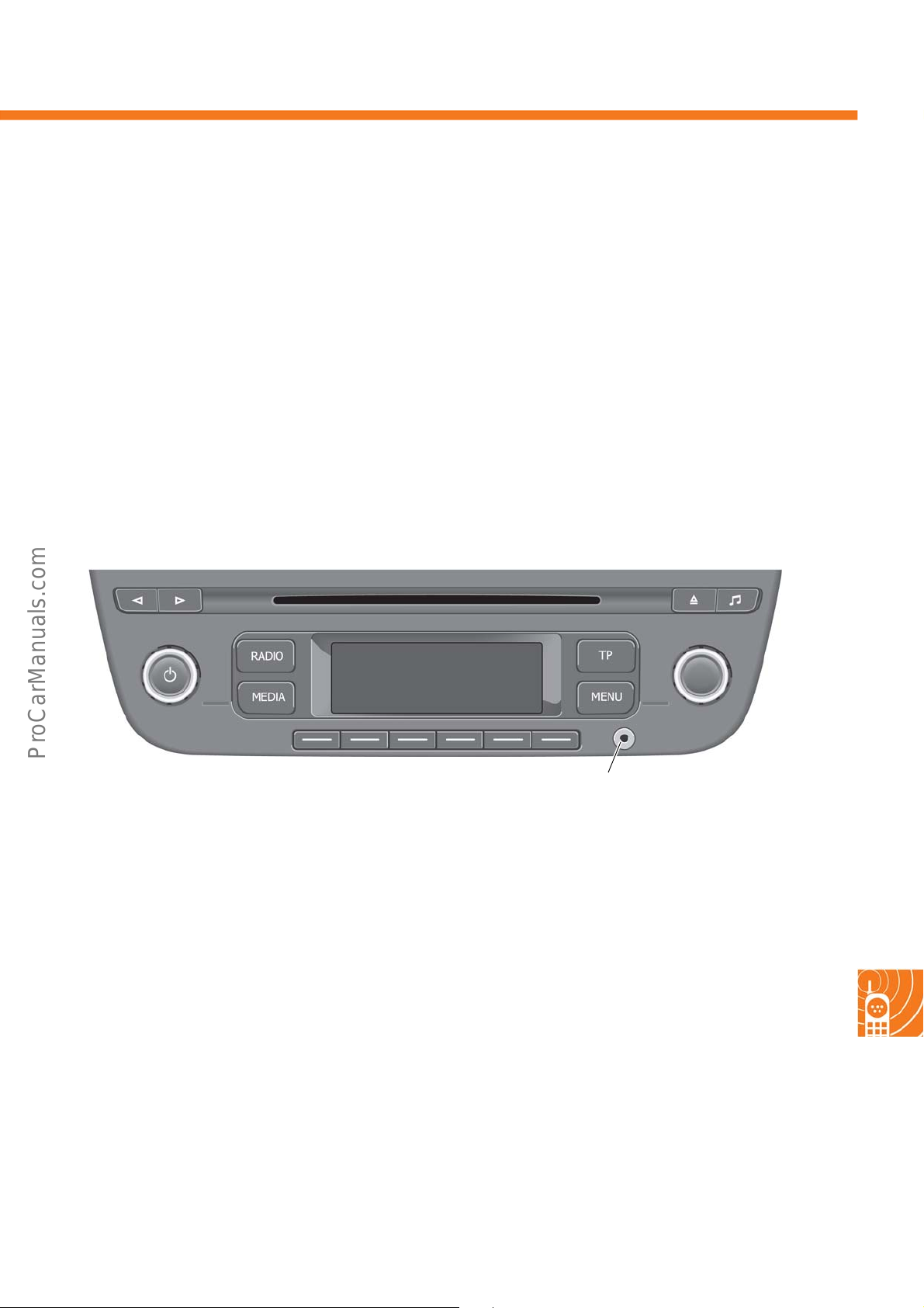
RCD 215 radio
Technical features
Infotainment
• Monochrome display (white/negative) with a
re
solution of 132 x 46 pixels
• Four output stages, each with 20 W
• Two or four speakers can be connected
• Red locator light
• FM, AM and RDS reception via a single tuner
•Integrated CD drive
• Media support for MP3 (with ID3 tag)
• Audio input interface (AUX-IN) in the front panel
• GALA (speed-dependent volume setting)
• Network via low speed CAN
Combination and enhancement options
The RCD 215 radio features an interface for
connect
system J982 (via J983) using two unidirectional LIN
lines. This means that in contrast to a standard LIN
protocol, the data is only sent in one direction on each
line.
ing the portable navigation and infotainment
s500_118
AUX-IN
Diagnosis
The radio features self-diagnostics and can therefore
e diagnosed using the VAS diagnostic tester.
b
35
Page 36
Infotainment
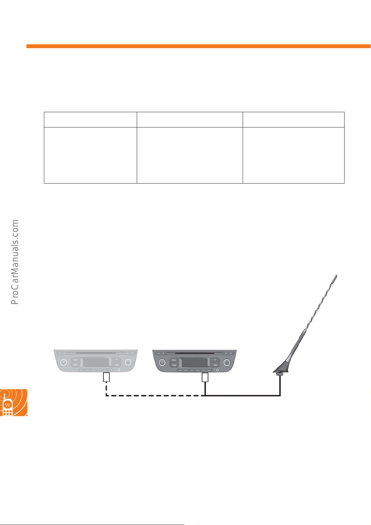
Aerial systems
There are 3 different equipment versions for the up!:
Without radio preparation With radio preparation With RCD 215 radio
If no radio is installed and the vehicle does not feature aerial technology, the hole for the aerial in the
plugged with
roof is
Radio preparation/radio with single-tuner
a stopper.
Radio preparation includes the power
supply line
position, speaker cables to the 4 speakers
(2 at the front and 2 at the rear) as well
as t
The AM/FM roof aerial and the CAN
connection are pre-prepared.
s up to the radio installation
he aerial cables.
When the
an active AM/FM rod aerial is installed
for
amplification electronics in the base of
the aerial.
A second aerial cannot be connected
up to the
RCD 215 radio is installed,
radio reception, which also features
RCD
215.
36
Radio preparation RCD 215
B = Coding on the aerial plug connection for a radio with supply voltage
BB
AM/FM
s500_024
Page 37
The navigation and infotainment system “maps + more”
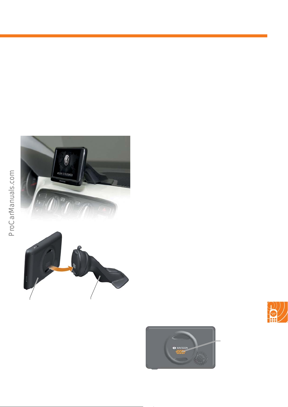
A further highlight in the up! is the navigation and infotainment system “maps + more”. It combines typical car
radio functions with the flexibility of a portable navigation system. The J982 portable navigation and infotainment
system is a commercial navigation system made by Navigon which has been enhanced with specific functions for
Volkswagen. It features a touch-sensitive 5" colour display (touch screen)
for display and operation. Voice information is he
ard via the vehicle
There is a cradle on the dash panel for operation in
the vehicle, which allows the
navigation and infotainment system to be
mechanically coupled. This cradle is the interface for
the J983 portable navigation and infotainment
system and, on the one hand, features a connection
for fixing it to the dash panel while, on the other
hand, it serves as the cradle for the J982 portable
navigation and infotainment system itself. All
connecting wires are contained in this cradle – the
power supply, audio and aerial connection and also
the communication lines to the vehicle network.
loudspeaker.
J982 portable
J982 portable navigation
and infotainment system
s500_050
s500_023
Interface for the J983
portable navigation and
infotainment system
There is a contact surface with 16 pins on the rear of
the J983 portable navigation and infotainment
system.
Contact surface
with 16 pins
s500_026
37
Page 38
Infotainment
Menu guidance
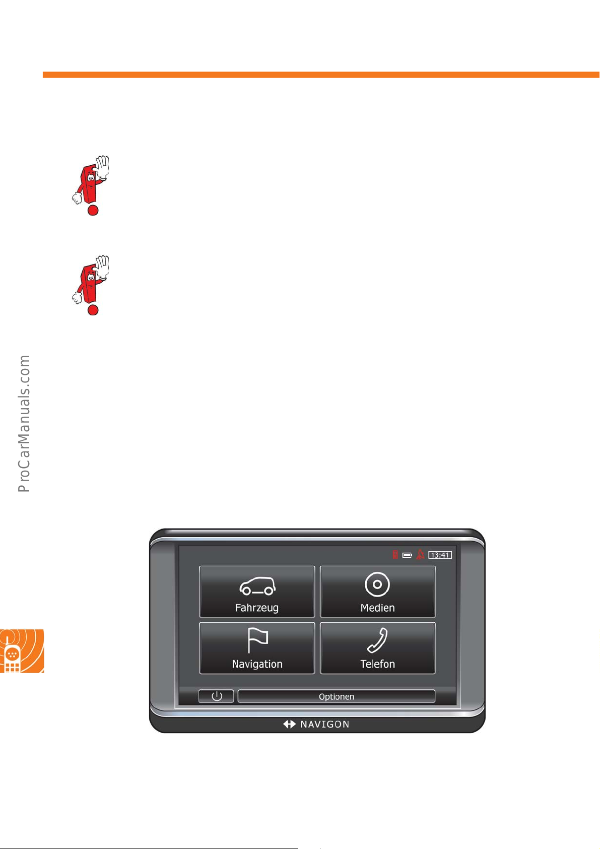
The following menu guidance only provides a brief introduction to the basic functions of the navigation
and infotainment system “maps + more”. A more detailed description can be found in the operating
instructions.
The display contents which are shown in the following pages correspond to the infotainment system
with the German system setting and serve merely as an example. Please refer to the corresponding
operating manuals for text content displayed in the relevant national languages.
Main menus
The navigation and infotainment system “maps + more” includes four main menus:
•Car Info
•Media
•Navigation
• Phone
38
s500_028
Page 39
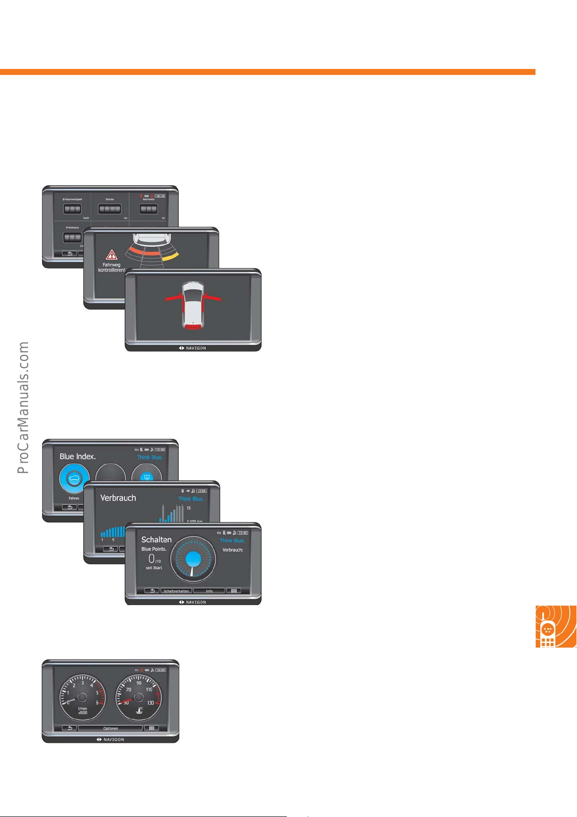
The “Car Info” menu
This menu includes the following sub-menus: “Trip Computer”, “Think Blue. Trainer” and “Status”.
Trip Computer
Information on the vehicle such as consumption, range
etc. is displayed in this menu i
display. This data is calculated by the dash panel insert
and made available to the navigation and
infotainment system. Furthermore, a vehicle status
display for the doors and boot lid is shown when the
equipment includes central locking. If a parking aid is
installed, OPS is activated when the reverse gear is
engaged.
s500_038
tem by a multifunction
s500_044
s500_062
Think Blue. Trainer
The system shows a consumption overvie
few minutes, and recommends the optimum gear to
the driver. Furthermore, the driver receives the
ThinkBlue! ecotrainer saving tips and direct feedback
on their style of driving.
Status
The additional analogue instruments, such as “rev
counter”
temperature”, can be displayed with their respective
measurements.
, “coolant temperature” or “outside
w for the last
39
Page 40
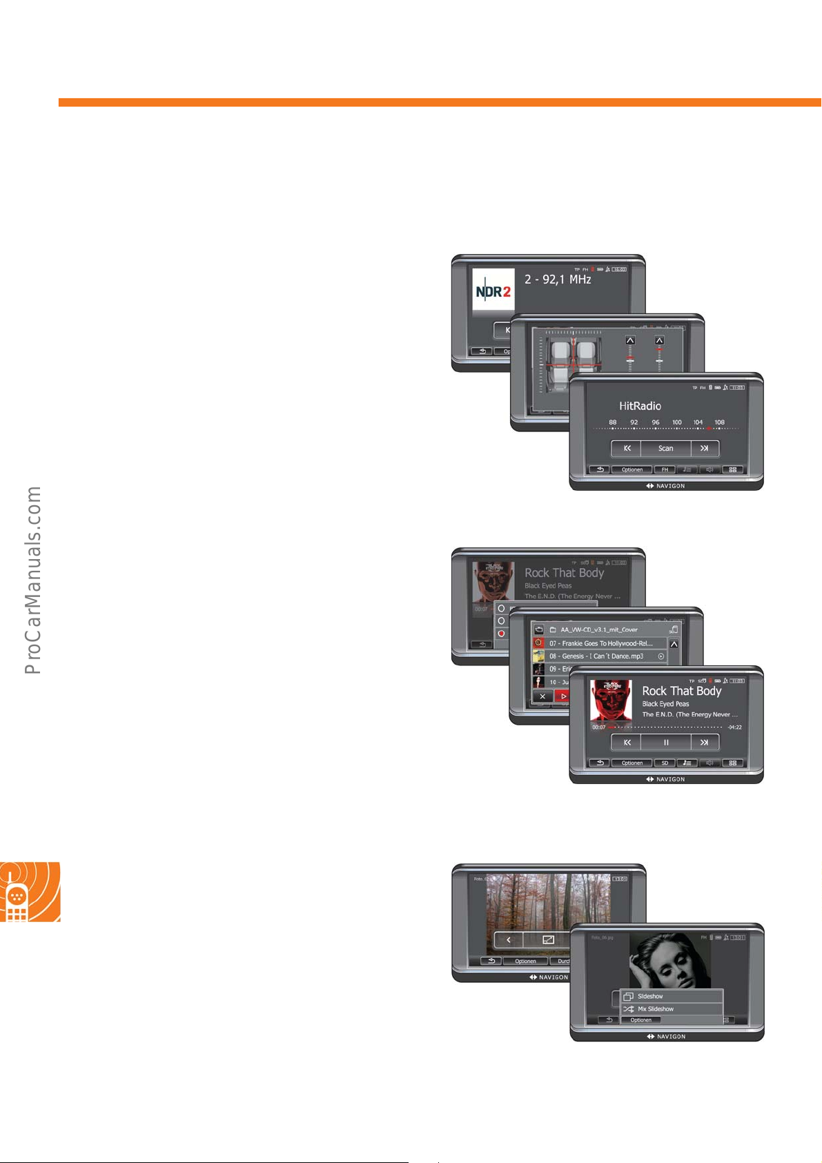
Infotainment
The “Media” menu
This menu includes the following sub-menus: “Radio”, “Media Player” as well as “Pictures”.
Radio
This menu is used to control the car radio, such as
selecting radio channels, settin
frequency, switching between FM/AM wave bands or
adjusting the volume and radio equalizer.
g the reception
Media Player
This menu is used to control the M
player, such as play/pause, track information display,
next/previous track, fast forward/rewind track.
Pictures
s500_072
P3 player or CD
s500_074
40
This menu allows you to display photos saved on a
micro S
“Slideshow” function is deactivated when the vehicle
is moving.
D card in the formats .jpg, .bmp or .png. The
s500_076
Page 41
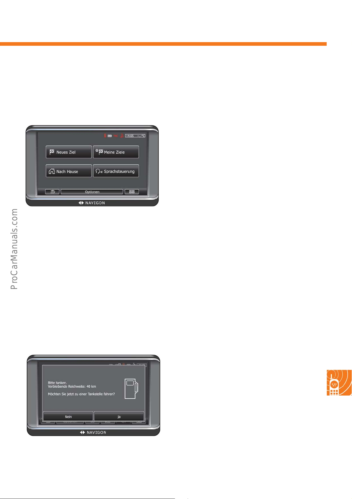
The “Navigation” menu
The navigation functions are the same as the ones featured by the commercial navigation device made by the
Navigon company. In the “Navigation” menu, the following sub-menus can be selected: “New Destination”, “My
Destinations”, “Take Me Home” as well as “Voice Command”.
A destination for which navigation has not yet been
s500_078
used, or whi
under “New Destination”. A list of destinations which
have already been entered and saved can be
accessed under “My Destinations”.
An address can be saved as a home address under
e Me
“Tak
any time by pressing one single button. The
destination can be entered by voice command under
“Voice Command”.
ch has not
Home”. Navigating there can be started at
been saved, can be entered
The commercial navigation device made by Navigon has been enhanced with the following specific functions for
Volkswagen:
• Low fuel warning
•Saving vehicle position
• Anti-theft protection
Low Fuel Warning
The Low Fuel Warning is active when the map has
been opened in
It appears as soon as the tank reserve symbol
appears in the vehicle's dash panel insert.
s500_080
standard mode or navigation mode.
41
Page 42
Infotainment
Saving vehicle position
The last position of the vehicle is automatically saved under the favourites in the menu “My Destinations”.
Anti-theft protection
The navigation device can be protected from unauthorised
required when the device is not set up in the vehicle and is switched on.
As soon as the device is set up in a vehicle, it receives the in
to determine whether it is set up in the “right” vehicle. In this vehicle, the password will only be required once.
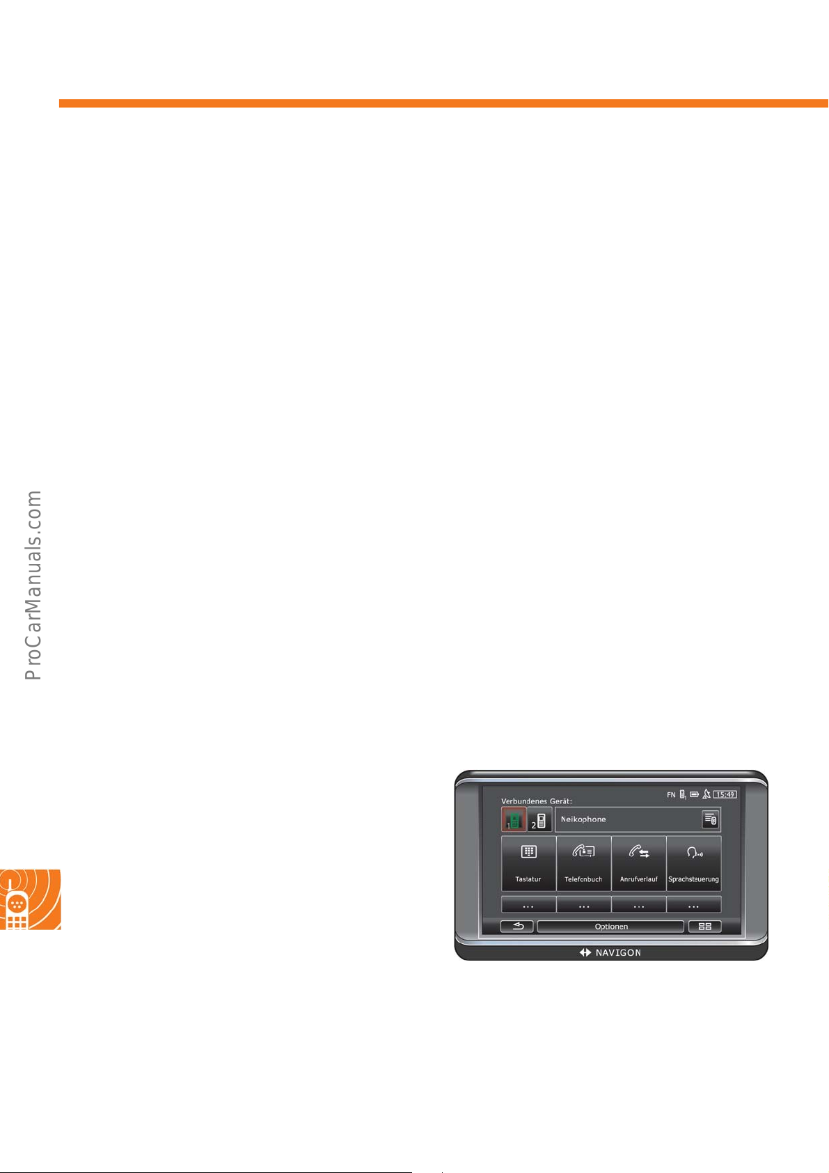
The “Phone” menu
The navigation and infotainment system features a hands-free module which supports Bluetooth connections to
Bluetooth-capable mobile telephones, MP3 players and headsets. It can be connected simultaneously to up to two
mobile telephones or MP3 players, one with one headset.
The “Phone” menu includes the following
Calls” and “Voice Command”.
sub-menus: “C
access by setting up a password. The password will be
dividual VIN from the vehicle. The device is then able
onnected Devices”, “Keyboard”, “Phone Book”, “Recent
42
„Connected Devices” displays tha
devices are connected to the navigation and
infotainment system. The keyboard for dialling
telephone numbers can be opened under
„Keyboard”. „Phone book” displays the telephone
book for the active telephone, and the call history of
the active telephone is opened under „Recent Calls”.
To make a call using voice command, the menu
„Voice Command” must be selected.
t Bluetooth-capable
s500_084
Page 43
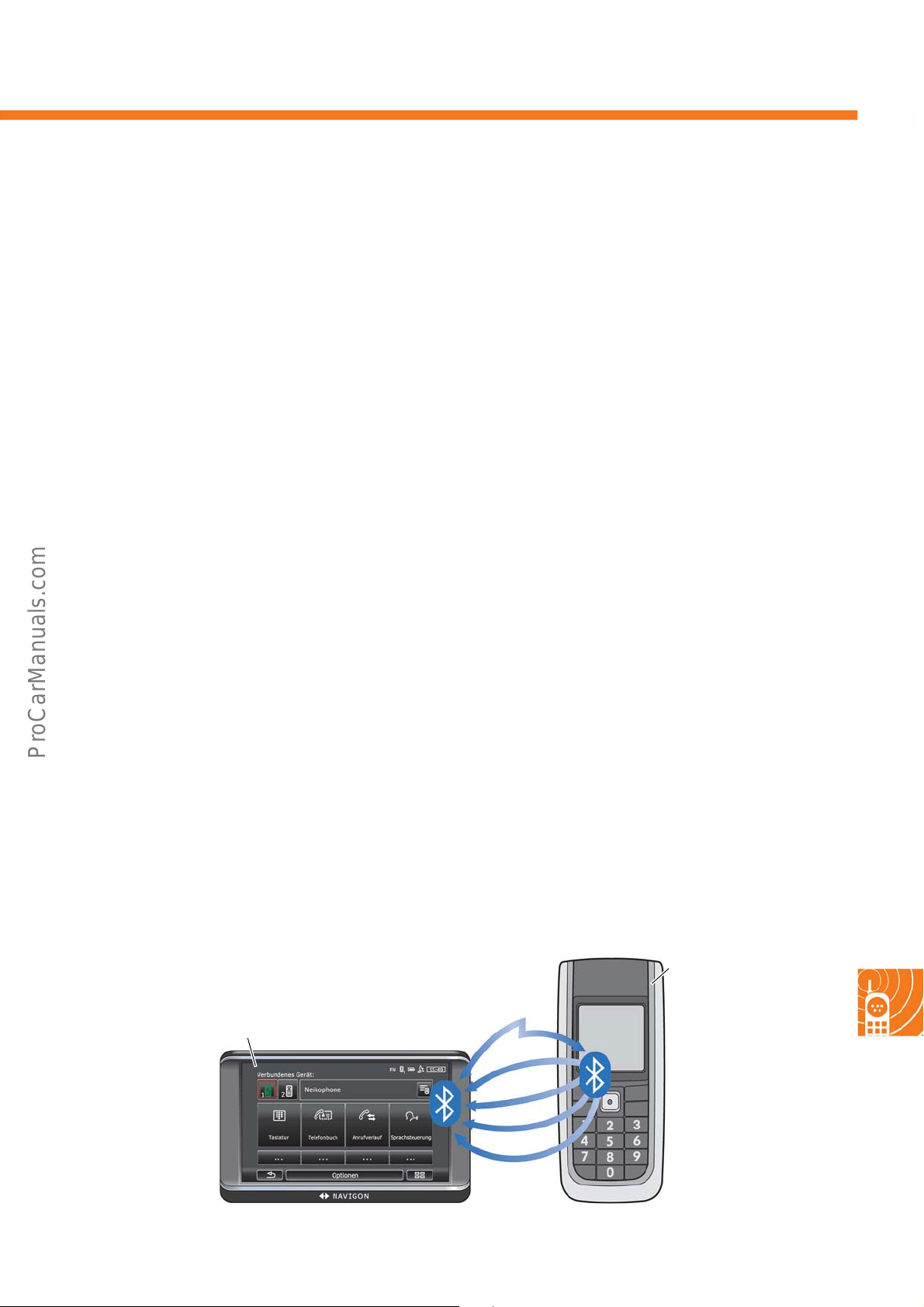
Universal cellphone preparation (UHV) with audio streaming
Universal cellphone preparation is implemented through the navigation and infotainment system “maps + more”. It
supports the following Bluetooth profiles:
ands Free Profile (HFP)
• H
U
sing the hands-free profile (HFP) a connection to a mobile telephone can be made via Bluetooth. The
crophone for the hands-free unit is included with the navigation and infotainment system “maps + more”. The
mi
voice output is played by the speakers in the vehicle. When the telephone is being used, any audio source
active beforehand is switched to mute.
• Phoneb
The Bluetoo
ook Access Profile (PBAP)
th-profile phonebook access profile (PBAP) allows the navigation and infotainment syst
more” to import the telephone book after being paired with the mobile telephone. A number can then be
selected using the navigation and infotainment system.
• Text to speech (TTS)
The navigation and infotainment system “maps + more” is able to
display short text messages (SMS)
paired mobile telephone and read them out loud, if required.
vanced Audio Distribution Profile (A2DP)
• Ad
In addition to making telephone calls, the navigation and inf
otainment system “maps + more” enables audio
streaming from the mobile telephone to the infotainment system via the Bluetooth profile “Advanced Audio
Distribution Profile” (A2DP).
• Audio V
AVRCP is the Bluetooth protocol for remote contro
i
deo Remote Control Profile (AVRCP)
l of audio data on the paired device.
em “maps +
from the
Navigation and infotainment system
“maps + more”
HFP
A
Bluetooth-capable
mobile phone
P
D
2
P
A
B
P
TS
T
CP
VR
A
s500_082
43
Page 44
500
500
© VOLKSWAGEN AG, Wolfsburg
All rights reserved. Subject to technical modifications.
000.2812.57.20 Technical status 11/2011
Volkswagen AG
After Sales Qualifizierung
Service Training VSQ-1
Brieffach 1995
D-38436 Wolfsburg
❀ This paper was manufactured using pulp bleached without the use of chlorine..
 Loading...