

Volkswagen Self Study Program 448 – Wheel Alignment – Basics SSP-448-Wheel-alignment-basics
Page 1
Service Training
Self-study Programme 448
Wheel Alignment – Basics
Page 2
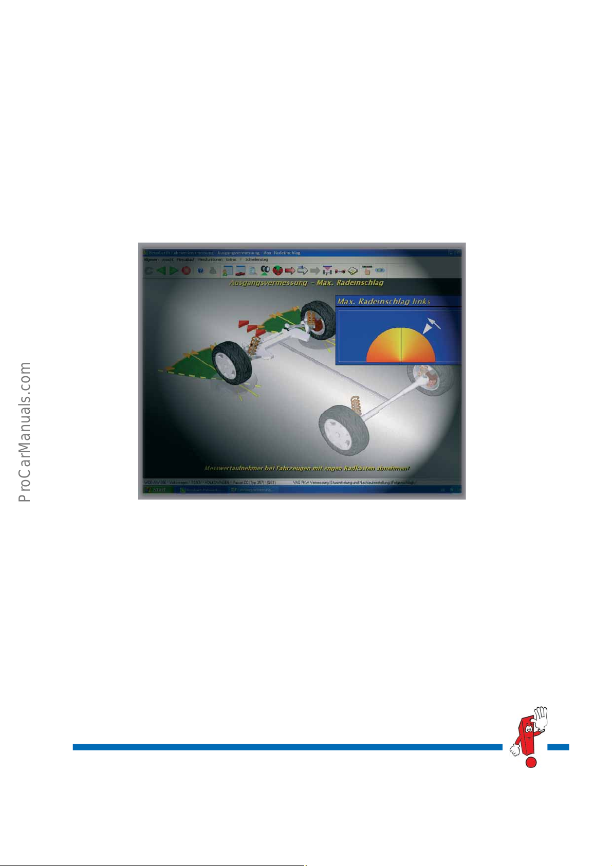
Today’s modern vehicles have increasingly complex and advanced suspension systems that need to fulfil the
requirements of comfort, sporty usage and especially road safety.
We now have very good means for measuring the suspension geometry and for correcting misaligned settings
to ensure that the high requirements set for the suspension system can also be met over the entire vehicle life
and after accidents.
In this self-study programme, you will learn about the background of wheel alignment,
for example:
● Suspension-related terms
● Preparation of the wheel alignment system
● Checking the wheel alignment system
● Why the alignment is carried out
● The tools used for wheel alignment
● How the alignment principle works
For current testing, adjustment and repair
instructions, refer to the relevant service literature.
S448_002
Important
Note
2
Page 3
Contents
Basics . . . . . . . . . . . . . . . . . . . . . . . . . . . . . . . . . . . . . . . . . . . . . . . . . . . . . . . . . . 4
Introduction . . . . . . . . . . . . . . . . . . . . . . . . . . . . . . . . . . . . . . . . . . . . . . . . . . . . . . 4
Design configuration – vehicle position X-Y-Z axis system . . . . . . . . . . . . . . . . 5
Suspension-related terms . . . . . . . . . . . . . . . . . . . . . . . . . . . . . . . . . . . . . . . . . . . 6
Wheel Alignment . . . . . . . . . . . . . . . . . . . . . . . . . . . . . . . . . . . . . . . . . . . . . . . 20
Why do the wheels need to be aligned? . . . . . . . . . . . . . . . . . . . . . . . . . . . . . 20
Workshop equipment for wheel alignment . . . . . . . . . . . . . . . . . . . . . . . . . . . 24
Carrying out the wheel alignment . . . . . . . . . . . . . . . . . . . . . . . . . . . . . . . . . . 31
Using Wheel Alignment Stands For Other Systems . . . . . . . . . . . . . . . . . . . 38
Driver assistance systems . . . . . . . . . . . . . . . . . . . . . . . . . . . . . . . . . . . . . . . . . . 38
Axles . . . . . . . . . . . . . . . . . . . . . . . . . . . . . . . . . . . . . . . . . . . . . . . . . . . . . . . . . 40
Types of axle . . . . . . . . . . . . . . . . . . . . . . . . . . . . . . . . . . . . . . . . . . . . . . . . . . . . 40
Flowchart . . . . . . . . . . . . . . . . . . . . . . . . . . . . . . . . . . . . . . . . . . . . . . . . . . . . . 44
Flowchart for wheel alignment . . . . . . . . . . . . . . . . . . . . . . . . . . . . . . . . . . . . . 44
3
Page 4

Basics
Introduction
The suspension system is the connecting link between
the vehicle and the road. Wheel contact forces, drive
forces and the lateral forces in corners are all
transferred through the suspension onto the road via
the wheels.
The suspension system is therefore subjected to a
number of forces and moments.
Increasing vehicle performance figures and also
greater expectations for vehicle comfort and vehicle
safety have led to a constant increase in requirements
for the suspension.
The structural design in the suspension kinematics has
resulted in increasingly complex alignment processes
and smaller tolerances in the adjustments.
To measure and, if necessary, re-align the suspension
kinematics, the suspension needs to be checked and
adjusted on a special wheel alignment stand.
It should be noted that the suspension should only be
adjusted after repairs or problems with the
suspension.
This self-study programme will provide you with an overview of wheel alignment – starting with the terms and
going onto the actual alignment.
Suspension design
The suspension consists of
● Wheel mountings
● Wheels
● Springs
● Shock absorbers
● Front and rear axles
● Steering
● Brakes including controls
● Subframes
4
Page 5
Design configuration – vehicle position in an X-Y-Z axis system
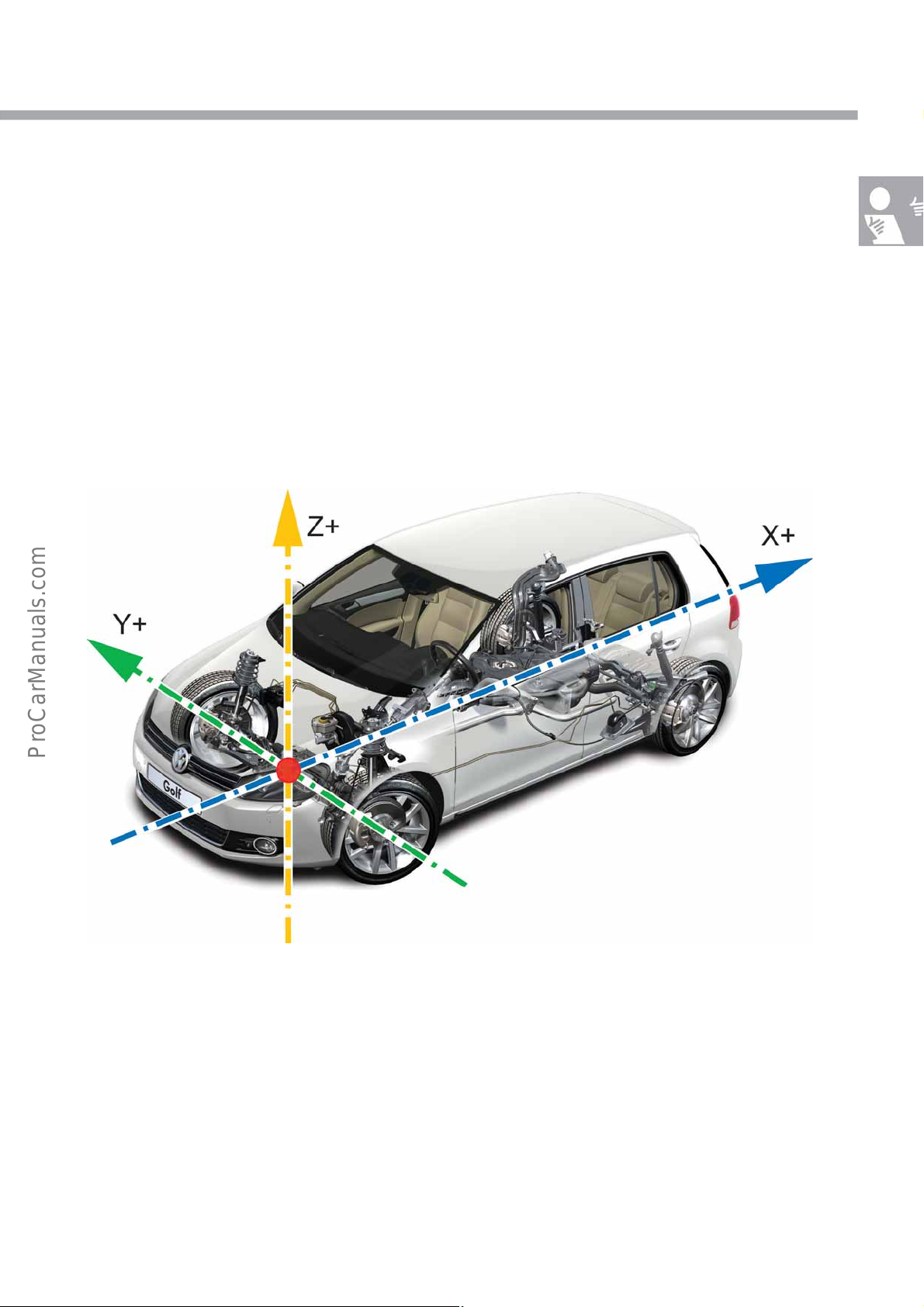
The design configuration is first defined during the
development of a vehicle. It is described by an X-Y-Z
axis system.
The Z- and the X-axes run through the centre of the
front axle, and the Y-axis normally runs exactly
through the centre of the front wheels. The design
configuration corresponds with the vehicle position at
the nominal ride height.
All nominal data specified by the vehicle
manufacturer relate to the design configuration.
If data is collected and compared during the wheel
alignment, the design configuration is always taken as
a reference – this concerns the suspension terms
described below.
S448_035
Ride height
The ride height has a decisive influence on the results of the wheel alignment. It is influenced by the load carried in
the vehicle, by the contents of the fuel tank or other liquid containers and also by temperature differences that can
cause the suspension measurements, for example, toe, camber and caster, to change.
5
Page 6
Basics
Suspension-related terms
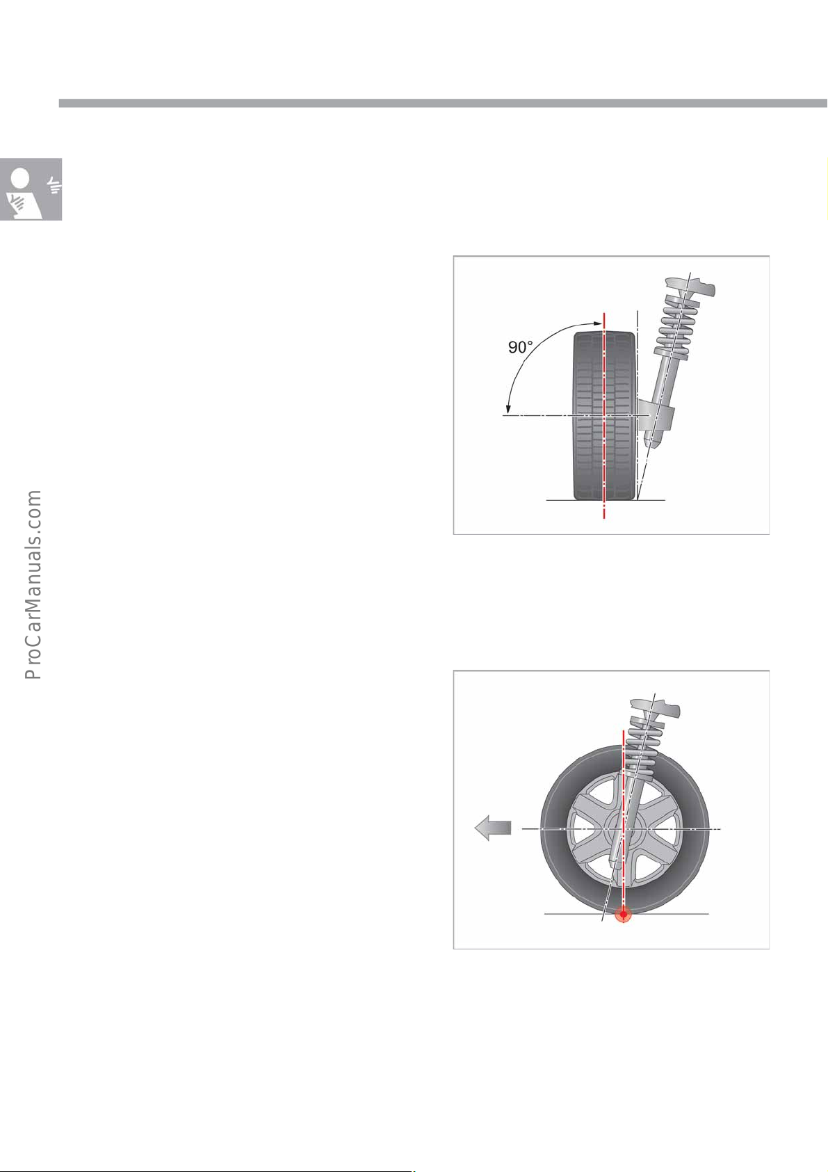
Wheel centre plane
The wheel centre plane intersects the wheel rotational
axis vertically in the centre of the tyre.
Wheel contact point
The wheel contact point is the point where a vertical
line passing through the wheel centre plane intersects
the rotational axis and the road surface.
S448_020
S448_023
6
Page 7
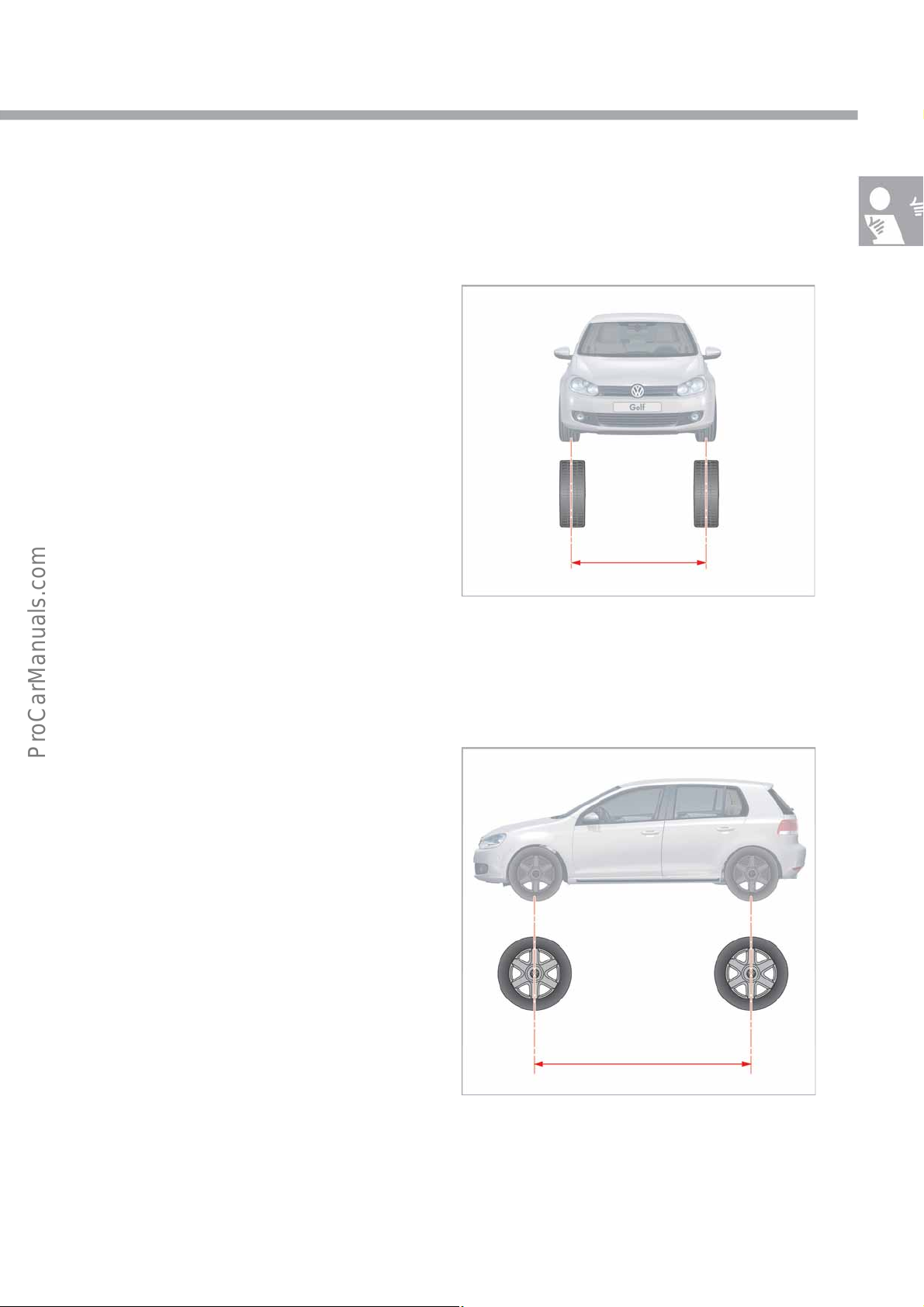
Track width
The track width is the measurement from tyre centre to
tyre centre on each axle.
On vehicles with independent wheel suspension using
traverse or semi-trailing links, the track width varies
during compression and extension cycles.
S448_011
Wheelbase
The wheelbase is the distance between the centres of
the wheels on the front axle and the rear axle.
S448_012
7
Page 8
Basics
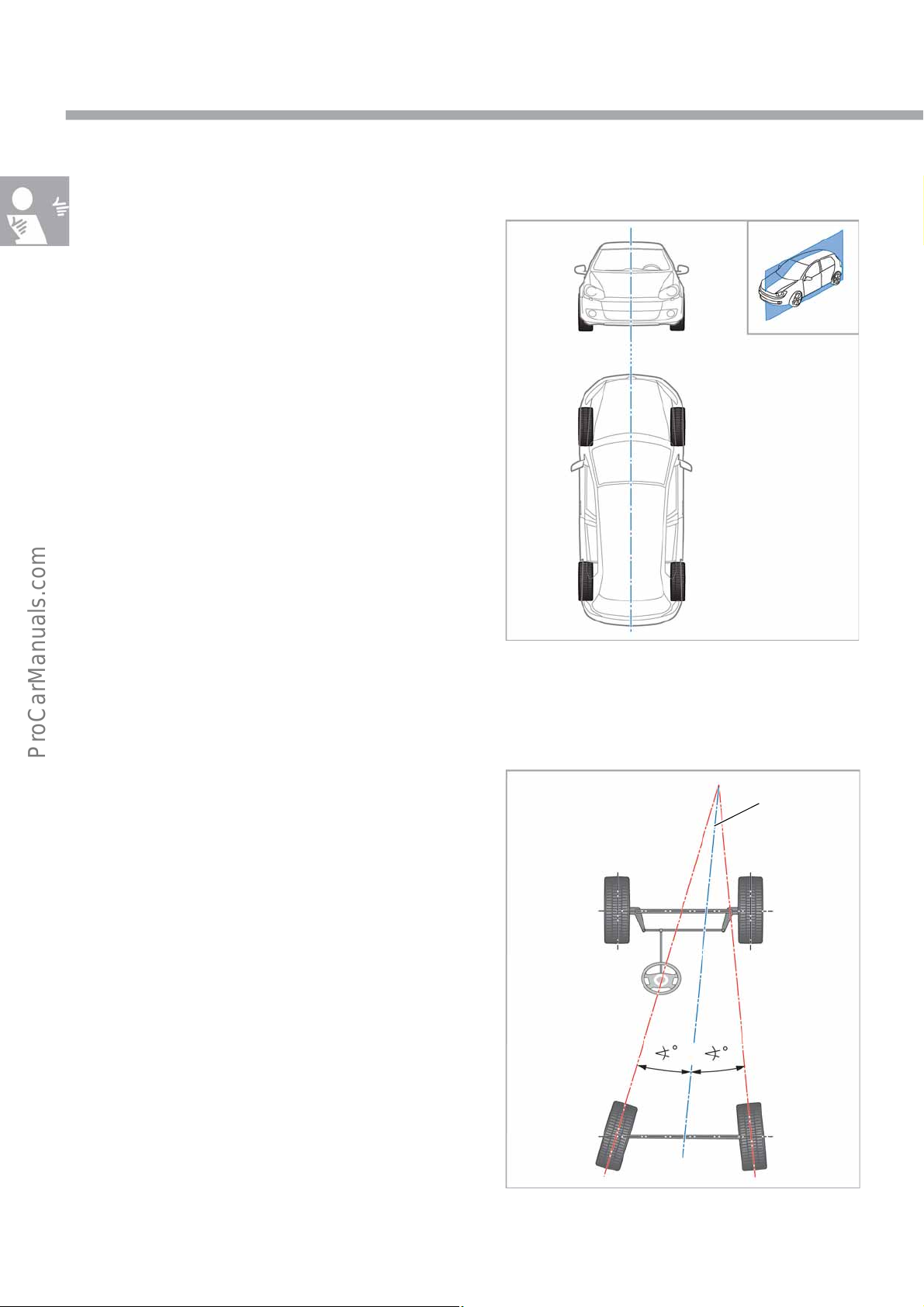
Vehicle longitudinal median plane
The longitudinal median plane of the vehicle is a fixed
vehicle-related plane that is vertical to the road and
passes through the centre of the track width of the
front and rear axle (X/Z plane).
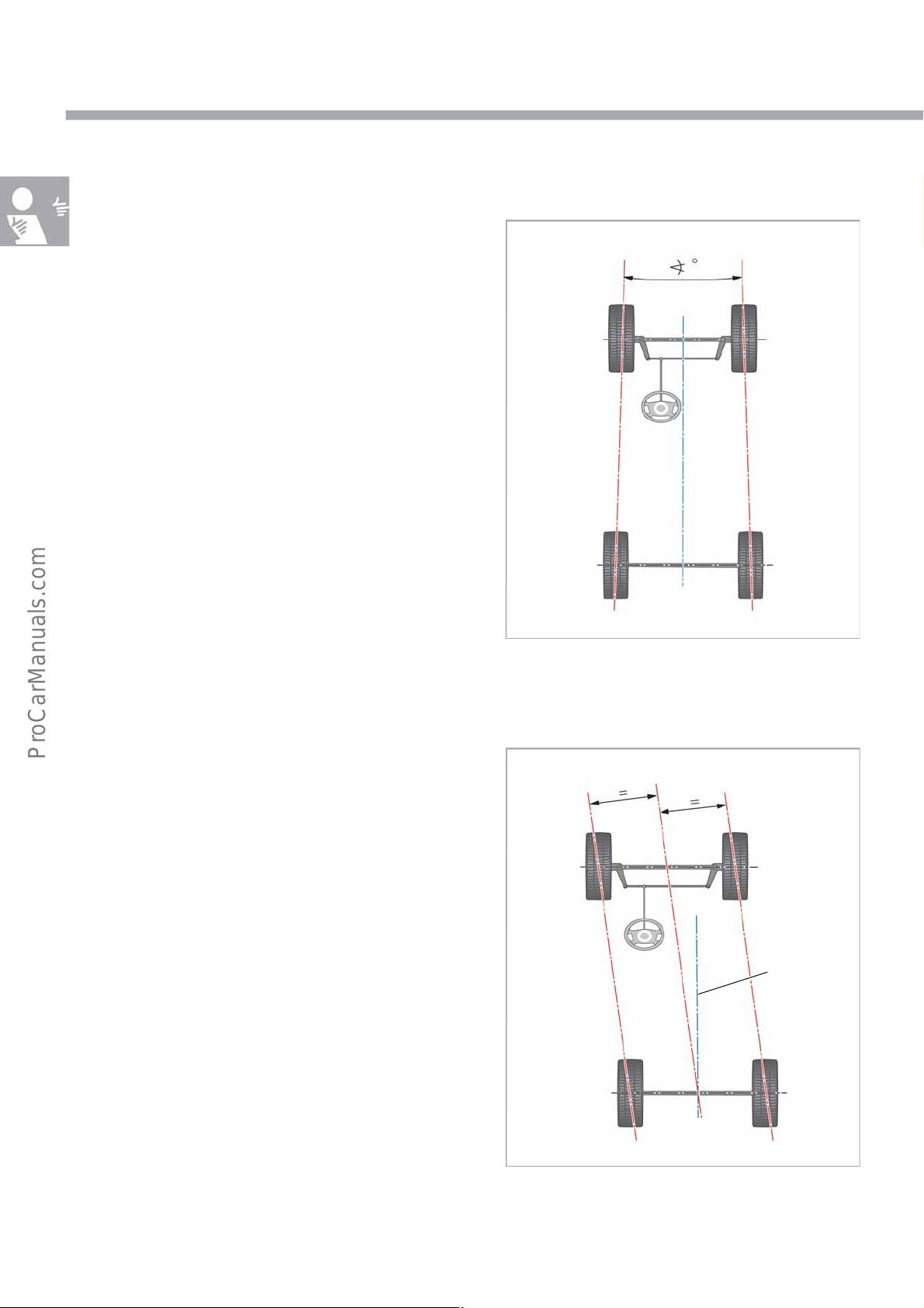
Thrust axis
The thrust axis bisects the total toe angle of the rear
axle.
The rear axle defines the tracking of the vehicle. For
this reason, all measurements for the front wheels and
for some assist systems are related to the thrust axis.
Ideally, the thrust axis should be along the vehicle
longitudinal median plane.
S448_014
Possible situation
S448_013
8
Page 9
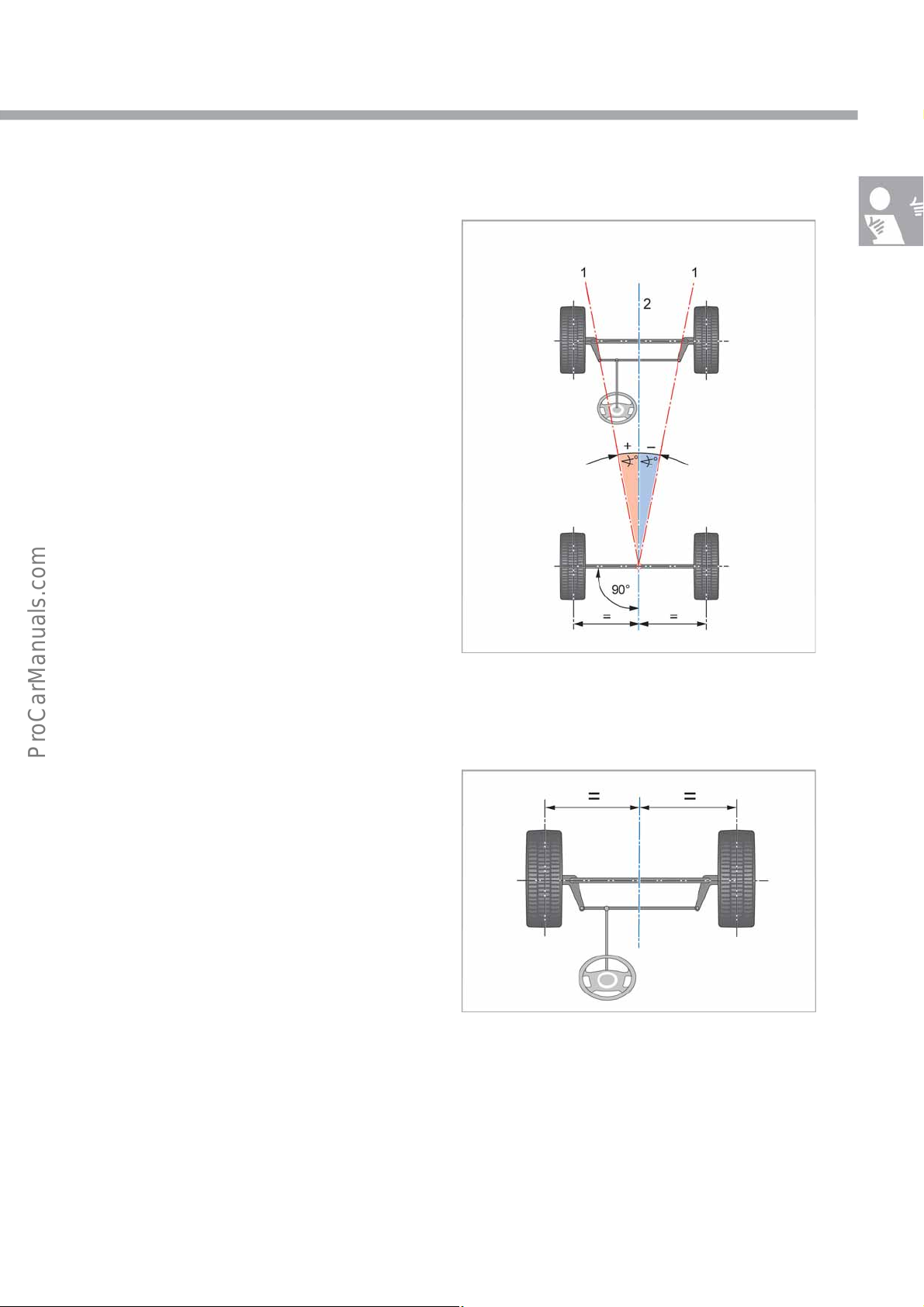
Thrust axis deviation
The thrust axis deviation is the angle between the
vehicle longitudinal median plane (2) and the thrust
axis (1).
It results from the thrust axis, the lateral offset and the
angle of the rear axle.
If the thrust axis deviation is oriented to the front left, it
is called positive. If it is oriented to the front right, it is
called negative.
Optimum thrust axis deviation
S448_015
Straight-ahead driving
This wheel position is a reference position in which the
two front wheels have the same toe angles to the
vehicle longitudinal median plane.
The rear axle is aligned in this position.
S448_016
9
Page 10
Basics
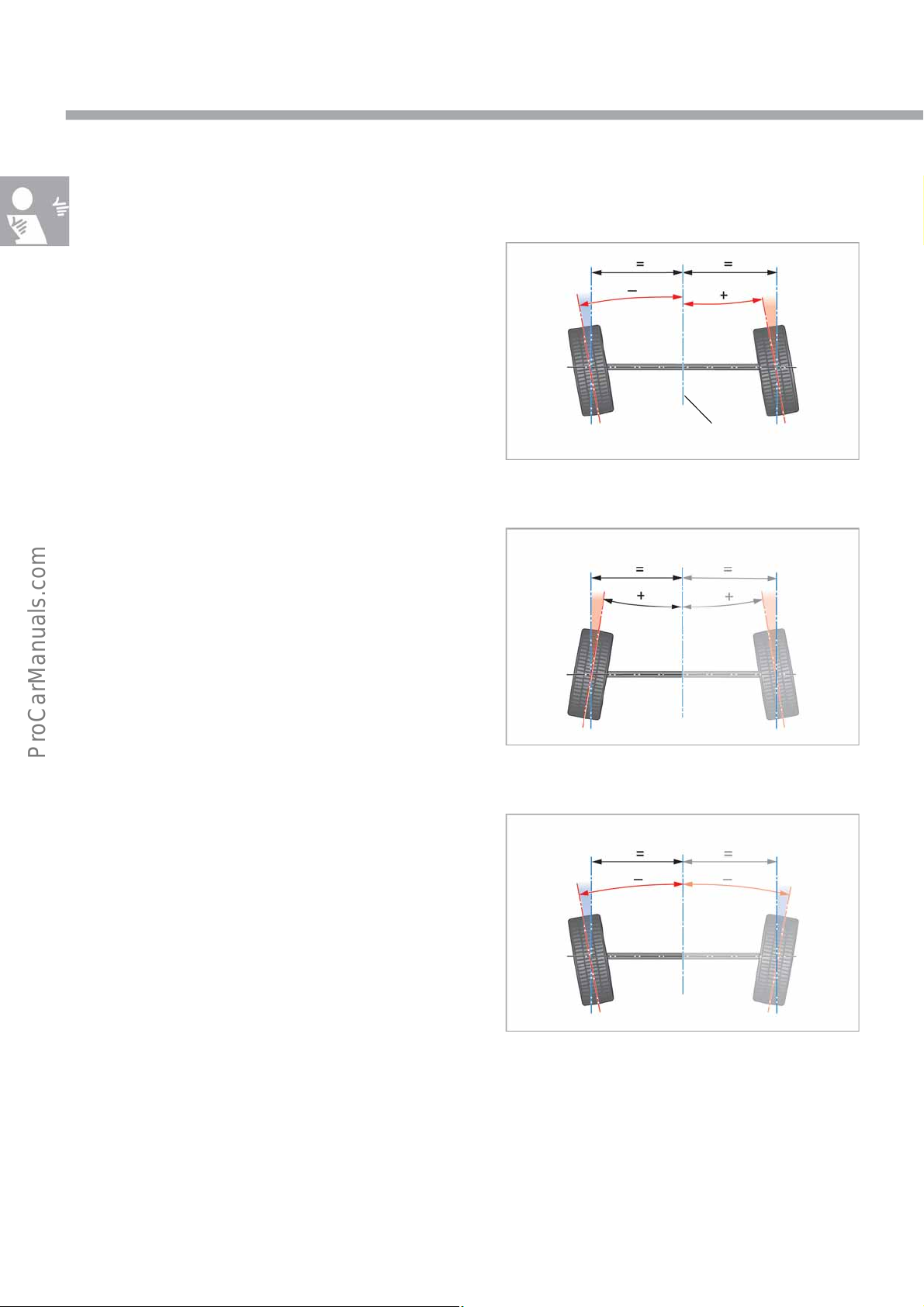
Toe angle of rear wheels
The toe angle of the rear wheels is the angle between
the vehicle longitudinal median plane and a line
intersecting the wheel centre plane.
Vehicle longitudinal
median plane
S448_112
It is positive (toe-in) when the front part of the wheel
points towards the vehicle longitudinal median plane.
It is negative (toe-out) when the front part of the wheel
points away from the vehicle longitudinal median
plane.
Toe -i n
S448_065
Toe -o ut
10
S448_018
Page 11
Individual toe angle of front
wheels
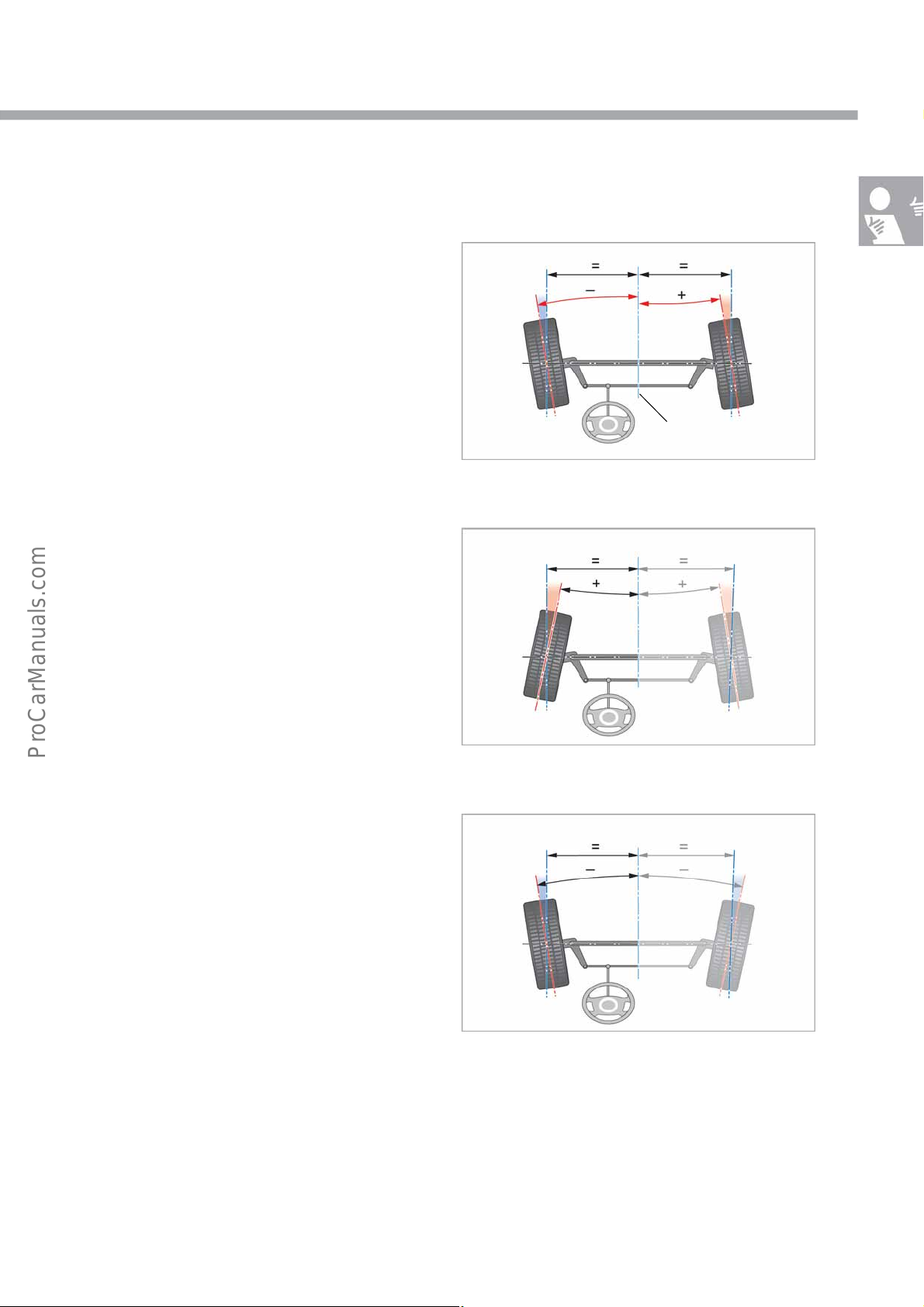
The individual toe angle of the front wheels is the
angle between the thrust axis and a line running
along the wheel centre plane.
Thrust axis
S448_113
It is positive (toe-in) when the front part of the wheel
points towards the thrust axis.
It is negative (toe-out) when the front part of the wheel
points away from the thrust axis.
Toe-in
S448_064
Toe-out
S448_017
Total toe
The total toe is the sum of the angles of the left and right wheels on an axle. The negative or positive sign in front of
the individual toe angles is important.
11
Page 12
Basics
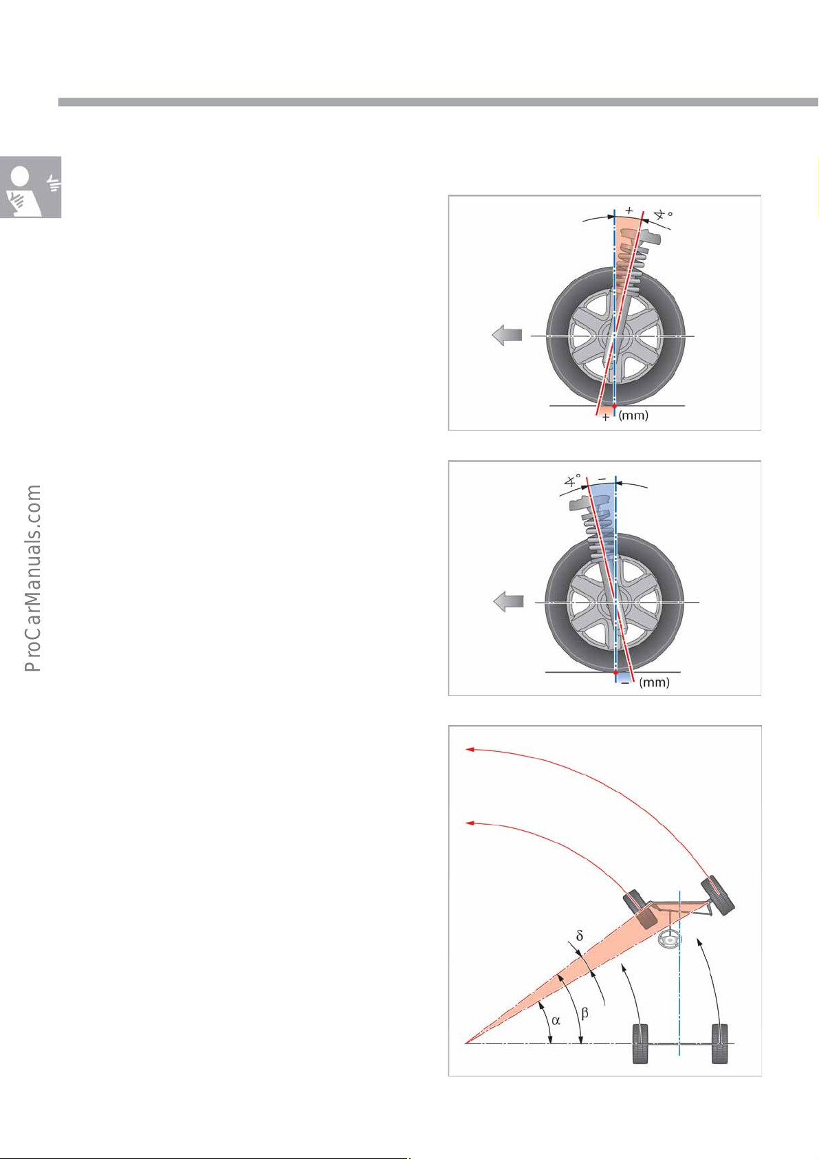
Camber
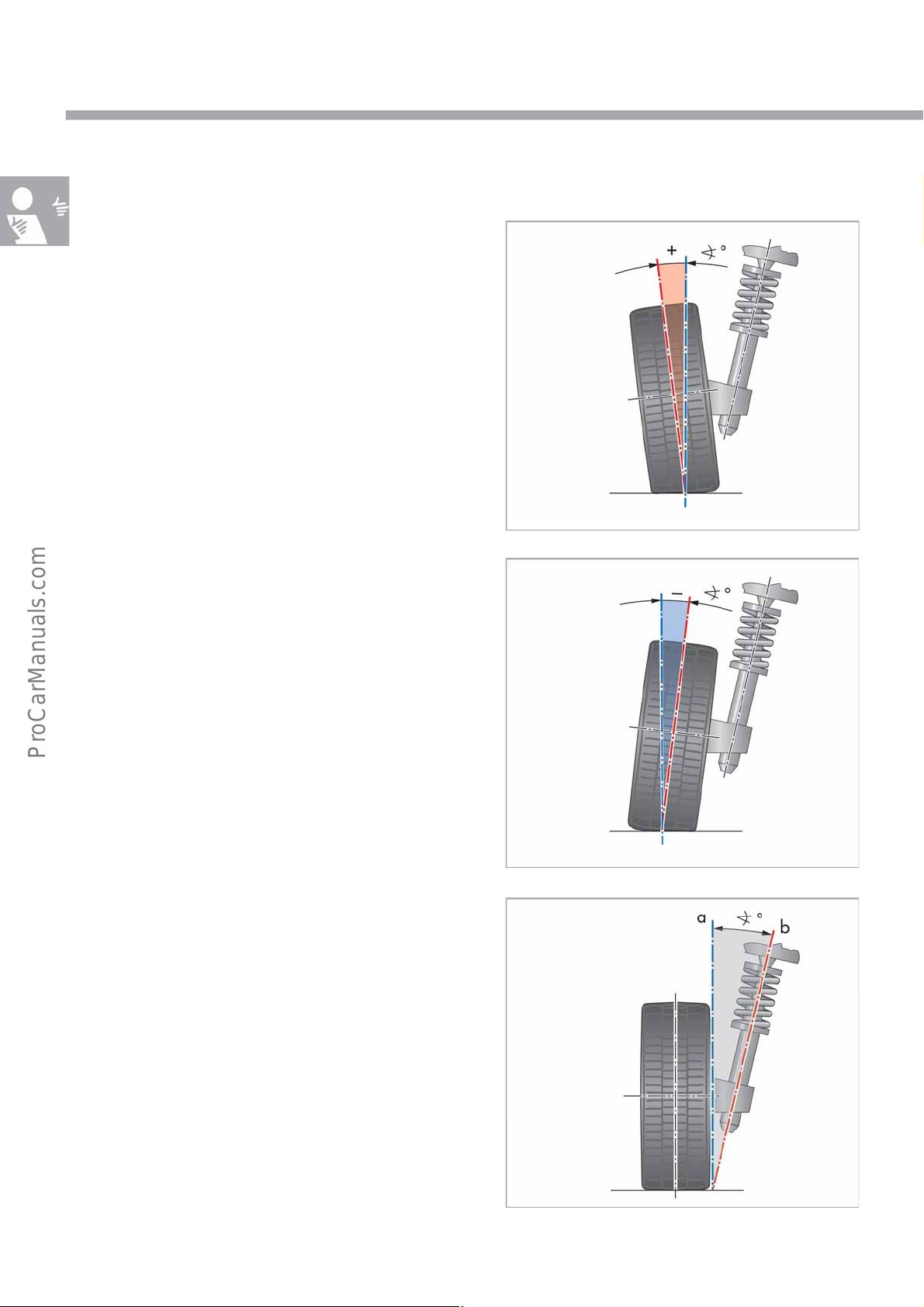
Camber is the angle between the wheel centre plane
and a vertical line passing through the wheel contact
point with the road surface.
Camber can be positive and negative.
● Positive (+) is when the upper part of the wheel is
inclined away from the wheel centre plane to the
outside.
● Negative (+) is when the upper part of the wheel
is inclined away from the wheel centre plane to the
inside.
Positive
S448_019
Negative
Steering axis inclination (SAI)
The steering axis inclination (also called king pin
inclination) is the angle of inclination of the steering
axis (b) from the true vertical (a) (parallel to the
vehicle longitudinal median plane).
The steering axis inclination causes the vehicle to lift
when steered thus generating steering return forces.
S448_071
12
S448_063
Page 13
Scrub radius
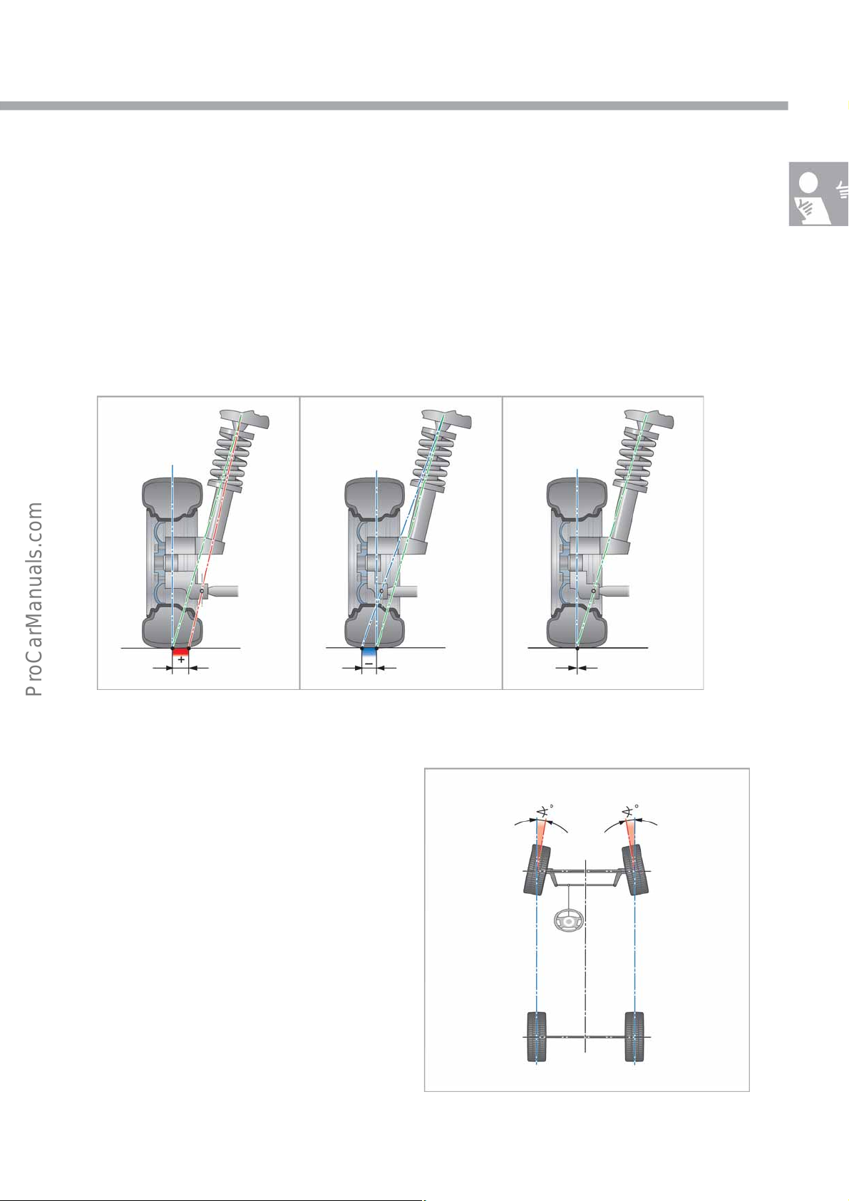
The scrub radius is the distance from the wheel
contact point to the point where the extended steering
axis meets the road surface.
Positive
scrub radius
scrub radius
Negative
The scrub radius can be positive (+), negative (–) or
zero.
The scrub radius results from the camber, steering axis
inclination and wheel offset.
Neutral
scrub radius
Scrub radius – tracking stability
If the scrub radius is negative, the wheel with the
greater frictional value is turned more to the inside –
autonomous countersteer results – the driver just has
to hold onto the steering wheel.
When the scrub radius is zero, the transfer of
interfering forces to the steering will be prevented if
the brakes pull to one side or there is a faulty tyre.
S448_021
S448_022
13
Page 14
Basics
Caster
Caster is the inclination of the steering axis along the
vehicle longitudinal axis from a vertical line to the
road surface.
Caster can be positive and negative.
● Positive: The “wheel contact point is behind the
point at which the steering axis intersects the road
surface” – the wheels are pulled => tracking
stability
● Negative: The “wheel contact point is in front of
the point at which the steering axis intersects the
road surface” – the wheels are pushed.
Positive
caster
S448_066
Negative
caster
Toe-out on turns
Toe-out on turns is the difference between the angles
of the inside and outside wheels when the vehicle is
cornering.
Toe-out on turns is determined by the Ackermann
steering geometry. It thus provides information on the
way the Ackermann steering geometry works for the
respective steering angle – to the left of right.
S448_067
14
S448_024
Page 15
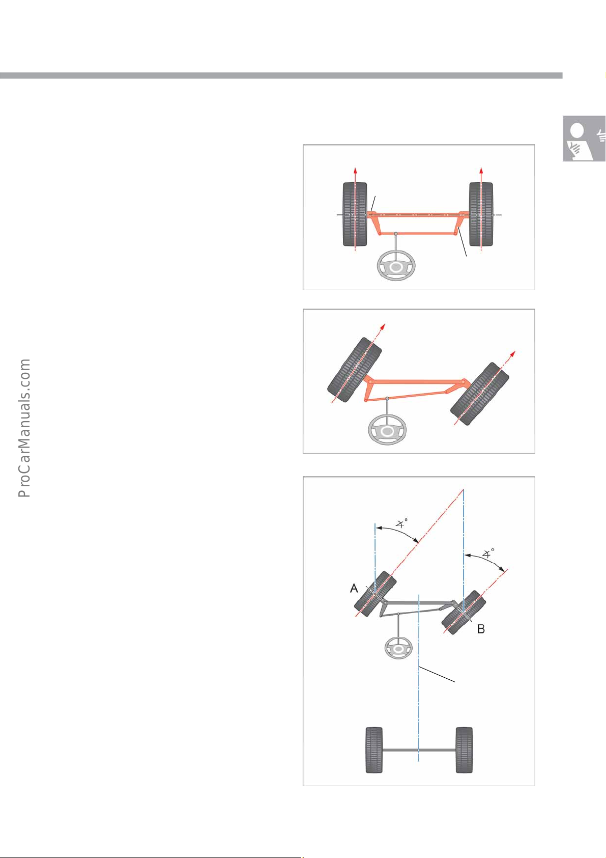
Ackermann steering geometry
The front axle, the steering arms and the steering rack
with the track rods form the Ackermann steering
geometry.
The Ackermann steering geometry creates the
different steering angles that are required when the
vehicle is cornering.
The steering knuckle and steering arms are not
positioned at a 90° angle to each other. This results in
unequal travel at the ends of the two steering arms
when the steering wheel is turned. Consequently the
wheels are turned at different angles.
Straight-ahead
Steering knuckle
Steering arm
S448_025
Cornering
Maximum steering angle
The maximum steering angle is the angle of the centre
plane of the inside wheel (B) and of the outside wheel
(A) relative to the vehicle longitudinal median plane
when the steering wheel is at full left or right lock.
The maximum steering angle should be the same on
both sides. The turning circles will then be the same.
S448_068
Vehicle longitudinal
median plane
S448_026
15
Page 16
Basics
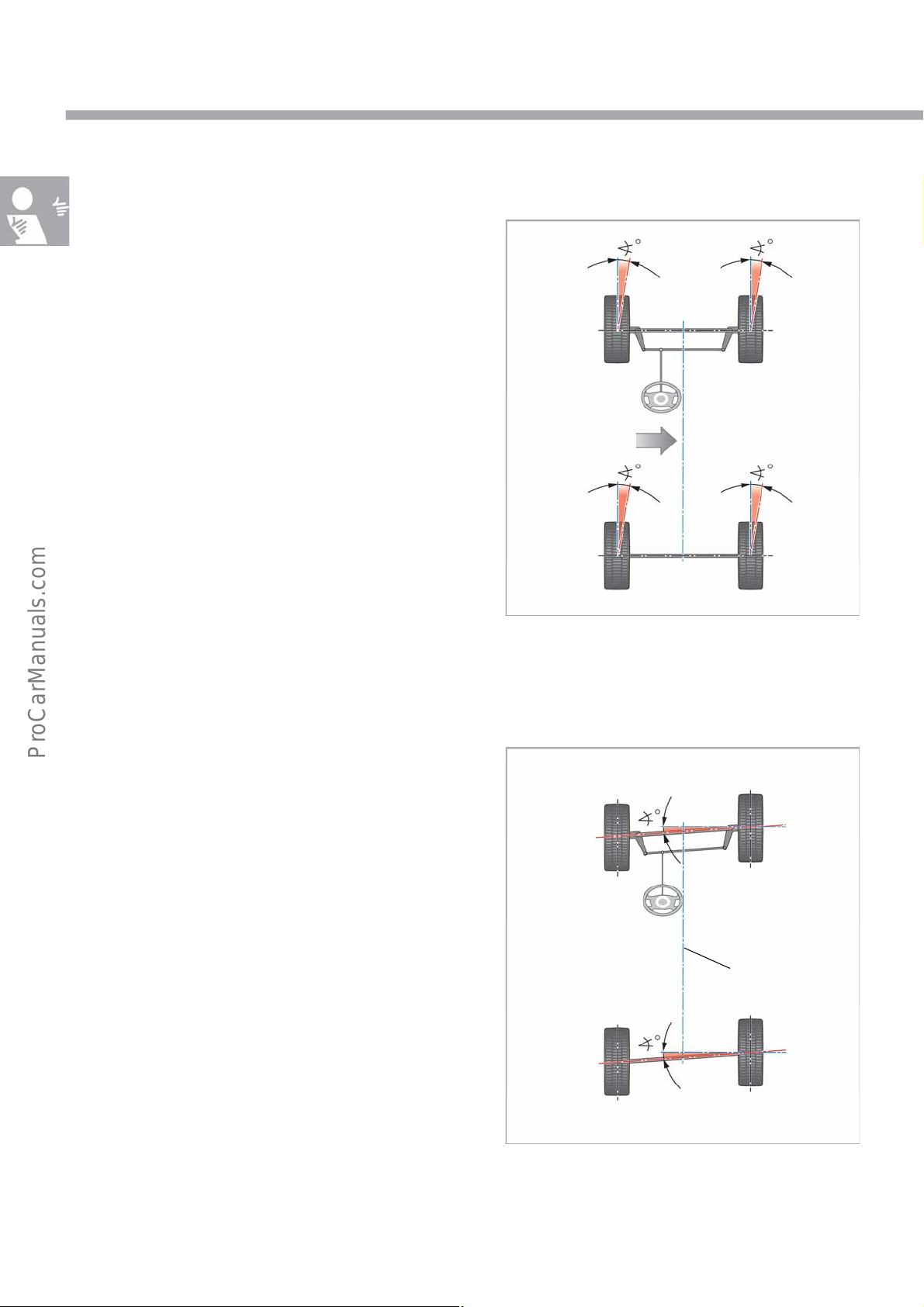
Slip angle
The slip angle is the angle between the wheel plane
and the direction of travel (direction that the wheel
moves).
A slip angle is formed when a rolling vehicle is
subjected to interfering lateral forces, for example,
wind and centrifugal forces. The wheels change their
direction of travel and run at a specific angle
diagonally to the original direction of travel.
If the slip angle is the same at the front and rear, the
handling will be neutral. If the slip angle is greater at
the front, the vehicle will understeer. If the slip angle is
greater at the rear, the vehicle will oversteer.
Lateral
interfering
forces
The slip angle depends on the wheel load,
interference force, tyre type, tyre tread, tyre inflation
pressure and static friction.
Wheel set-back
The wheel set-back is the angle between a line
connecting the wheel contact point and a line that
runs at 90° to the thrust axis.
The wheel set-back can be positive and negative.
● Positive – right wheel is set to the front
● Negative – right wheel is set to the rear
S448_027
Thrust axis
16
S448_028
Page 17
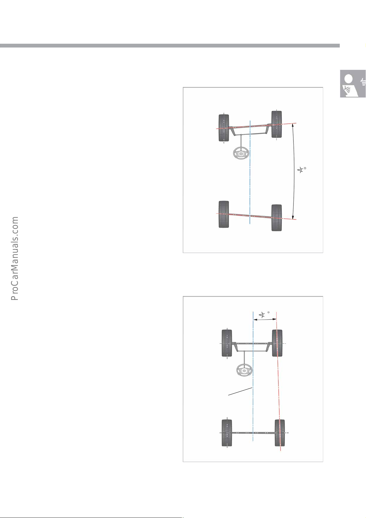
Wheelbase difference
The wheelbase difference is the angle between a line
connecting the front wheel contact points and a line
connecting the rear wheel contact points.
The wheelbase difference can be positive and
negative.
● Positive – the wheelbase is longer on the right-
hand side than on the left-hand side
● Negative – the wheelbase is shorter on the right-
hand side than on the left-hand side
Lateral offset
The lateral offset is the angle between a line
connecting the wheel contact points of the right-hand
or left-hand front and rear wheels and the thrust axis.
The lateral offset can be used to diagnose possible
body damage.
S448_029
Thrust axis
S448_030
17
Page 18
Basics
Track width difference
The track width difference is the angle between a line
connecting the wheel contact points of the left-hand
front and rear wheels and a line connecting the wheel
contact points of the right-hand front and rear wheels.
The track width is positive if the rear track width is
larger than the front track width.
Axle offset
The axle offset is considered to be positive if the rear
axle is offset to the right of the front axle in relation to
the thrust axis.
The axle offset can be used to diagnose possible body
damage.
S448_031
Thrust axis
18
S448_032
Page 19
Wheel offset
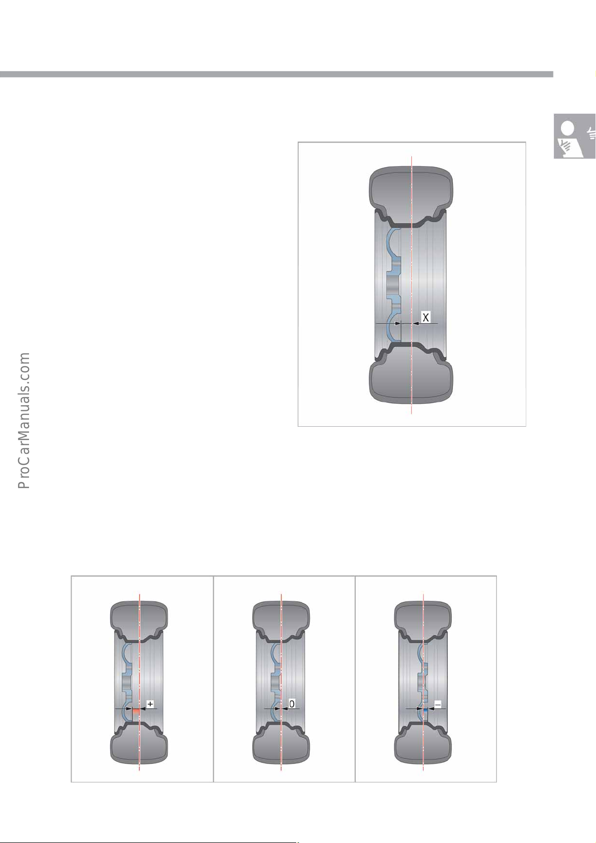
The wheel offset is the measurement from the
centreline of the wheel to the hub mounting surface
of the wheel (“x”).
The wheel offset influences the track width and the
scrub radius.
S448_033
One must distinguish between three variants of wheel offset
● Zero – If the hub mounting surface is precisely on the centreline of the wheel
● Positive – If the hub mounting surface, relative to the centreline of the wheel, is offset to the outside of the wheel
– reduction in track width
● Negative – If the hub mounting surface, relative to the centreline of the wheel, is offset to the inside of the wheel
– increase in track width
Positive Zero Negative
S448_034
19
Page 20
Wheel Alignment
Why do the wheels need to be aligned?
Correct wheel alignment is necessary to run a vehicle
with optimum handling and minimum tyre wear.
Incorrect adjustment, for example, of the toe or
camber, caused by wear or accidents will affect the
road safety of the vehicle.
Impermissible deviations in the wheel alignment can
also occur following repairs, for example, when
suspension parts are replaced.
Incorrect alignment can lead to incorrect wheel
positions, which can consequently cause damage
to the tyres.
If handling problems or noticeable wear occur, wheel
alignment can be used to diagnose the causes and
determine what action needs to be taken to restore
the correct suspension set-up.
Wheel alignment should only be
performed by properly trained personnel.
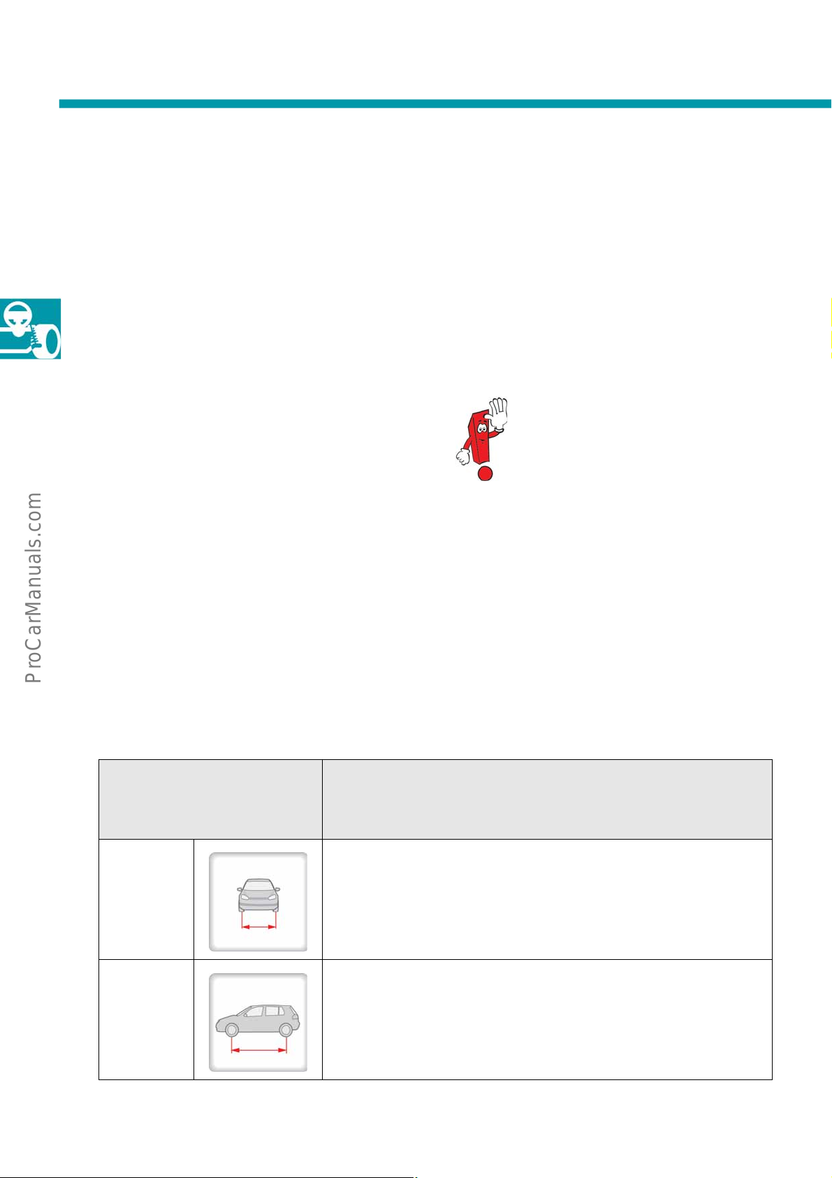
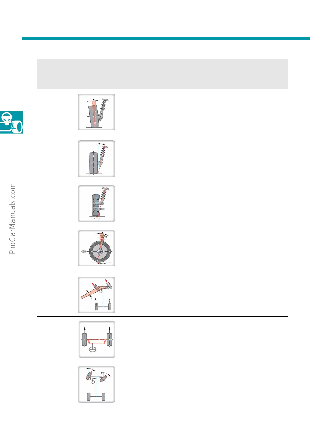
Suspension parameters – Effects of faults – Adjustment possibilities
The suspension parameters are distinguished by non-adjustable original and reference design parameters and
adjustable parameters. These will be explained separately in the following table.
Suspension parameter
(basic terms)
Track width Original and reference design parameter – therefore faults have no effect
Wheelbase Original and reference design parameter – therefore faults have no effect
Effect of fault – Adjustment possibility
● Non-adjustable suspension parameter
● Non-adjustable suspension parameter
20
Page 21
Suspension parameter
(basic terms)
Effect of fault – Adjustment possibility
Wheel centre
Original and reference design parameter – therefore no fault effects
plane
● Non-adjustable suspension parameter
Wheel contact
Original and reference design parameter – therefore no fault effects
point
● Non-adjustable suspension parameter
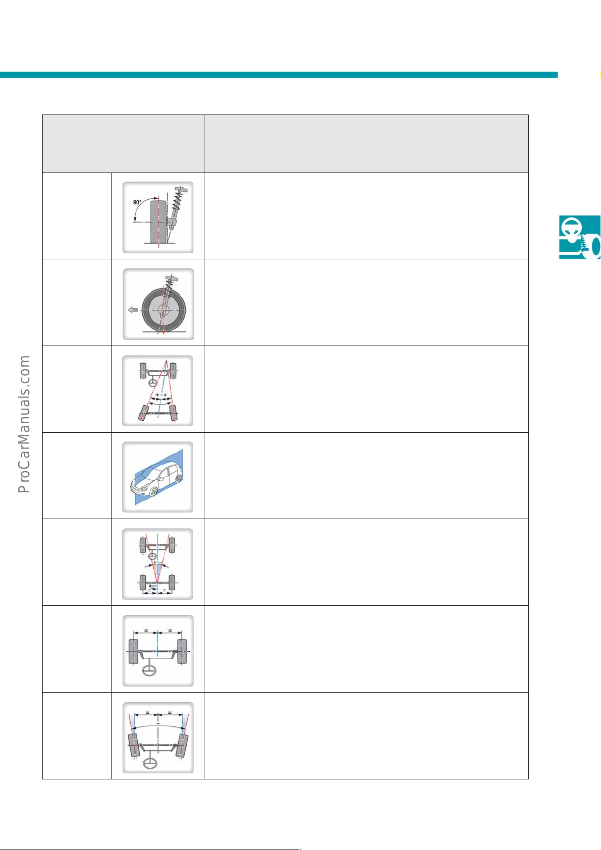
Thrust axis If this straight line deviates from the vehicle longitudinal median plane, a thrust
axis deviation results and the vehicle will run to one side – this is known as
“crabbing”.
● Adjustable suspension parameter
Veh ic le
Original and reference design parameter – therefore no fault effects
longitudinal
median plane
● Non-adjustable suspension parameter
Thrust axis
deviation
Straight ahead In this wheel position, the front wheels are set at the same individual toe angle to
Toe Too much negative toe (toe-out): Wear on inside of tyre and poor
If the thrust axis deviation is an angle other than zero, the vehicle will run to one
side – this is known as “crabbing”.
● Adjustable suspension parameter
the vehicle longitudinal median plane.
The rear axle is aligned in this position.
straight running
Too much positive toe (toe-in): Wear on outside of tyre and poor
straight running
● Adjustable suspension parameter
21
Page 22
Wheel Alignment
Suspension parameter
Effect of fault – Adjustment possibility
(basic terms)
Camber Too much negative camber: Better directional stability in corners, but one-sided
overloading and consequently greater wear on inside of tyre
Too much positive camber: Poorer directional stability, increased wear on the
outside of the tyre
● Vehicle-dependent adjustable suspension parameter
Steering axis
inclination
(SAI)
Steering axis inclination too large: High steering and holding forces
Steering axis inclination too small: Poor steering wheel return, sensitive to tyre
faults, vehicle may pull to one side
Right/left steering axis inclination different: Vehicle tends to pull to side
● Non-adjustable suspension parameter
Scrub radius The scrub radius is influenced by the camber, steering axis inclination and wheel
offset and can therefore only be changed by adjusting these parameters.
● Non-adjustable suspension parameter
Caster Too much positive caster: High steering and holding forces
Toe-out on
turns
Ackermann
steering
geometry
Max. steering
angle
Too much negative caster: Poor steering wheel return, sensitive to tyre faults
Right/left caster different: Vehicle tends to pull to side
The caster changes, for example, depending on the load in the luggage
compartment.
● Vehicle-dependent adjustable suspension parameter
Original and reference design parameter – therefore no fault effects
● Non-adjustable suspension parameter
The front axle, the steering arms and the steering rack with the track rods form the
Ackermann steering geometry.
The Ackermann steering geometry creates the different steering angles that are
required when the vehicle is cornering.
● Non-adjustable suspension parameter
If the maximum steering angle differs for left/right full lock, the turning circle
will be different on the left and right.
This is a design specification.
22
● Adjustable suspension parameter
Page 23
Suspension parameter
Effect of fault – Adjustment possibility
(basic terms)
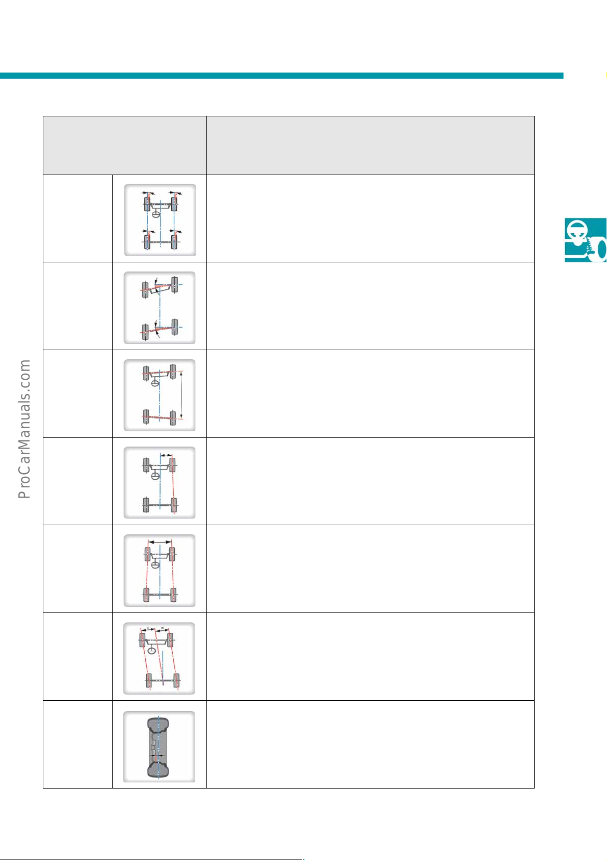
Slip angle The slip angle results from the parameters wheel load, lateral force, tyre design,
tyre tread, tyre inflation pressure and static friction coefficient.
● Non-adjustable suspension parameter
Wheel set-
The wheel set-back is a measure of the angle of an axle.
back
● Non-adjustable suspension parameter
Wheelbase
The wheelbase difference is a measure of the angle of the axles.
difference
● Non-adjustable suspension parameter
Lateral offset Lateral offset can result from body damage.
● Non-adjustable suspension parameter
Track wid t h
difference
A track width difference can result from body damage.
● Non-adjustable suspension parameter
Axle offset Axle offset can result from body damage.
● Non-adjustable suspension parameter
Wheel offset Original and reference design parameter
23
Page 24
Wheel Alignment
Workshop equipment for wheel alignment
Special components are used for wheel alignment. They will be described over the following pages.
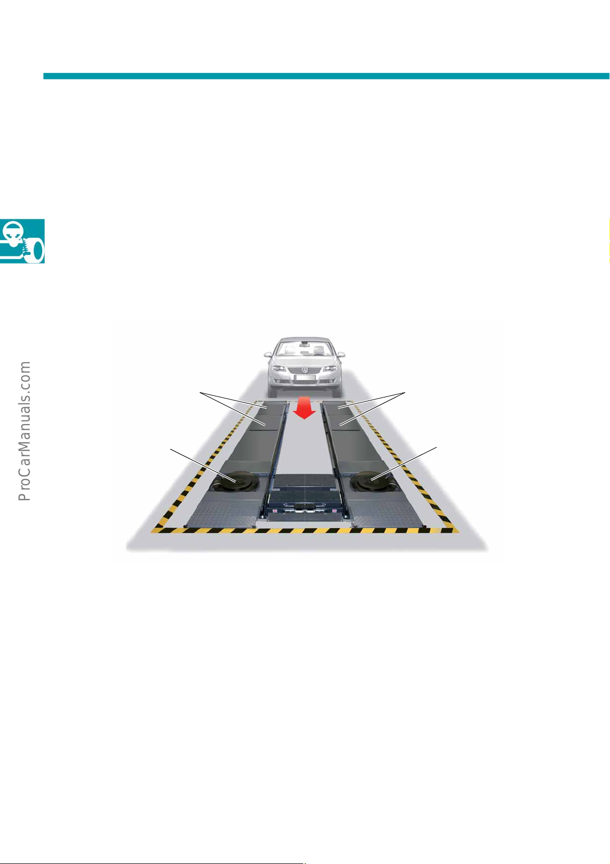
Wheel alignment platform
A special wheel alignment platform is used for wheel alignment.
Turntable Turntable
In order to perform a precise wheel alignment and also to ensure reproducible measuring results, this alignment
set-up must meet certain requirements.
● The wheel alignment platform must be clean and
the turntables and sliding plates must move
smoothly.
● The turntables and sliding plates should be locked
in place with pins or similar locking devices so that
they cannot move while the vehicle is driven onto
or off the platform.
Sliding plate Sliding plate
S448_037
● All wheel contact points must be at the same
height.
The maximum permitted height differences should
be maintained both in the lowered position for the
initial and final measurements and in the raised
position for the adjustment work.
24
Page 25
Wheel alignment system
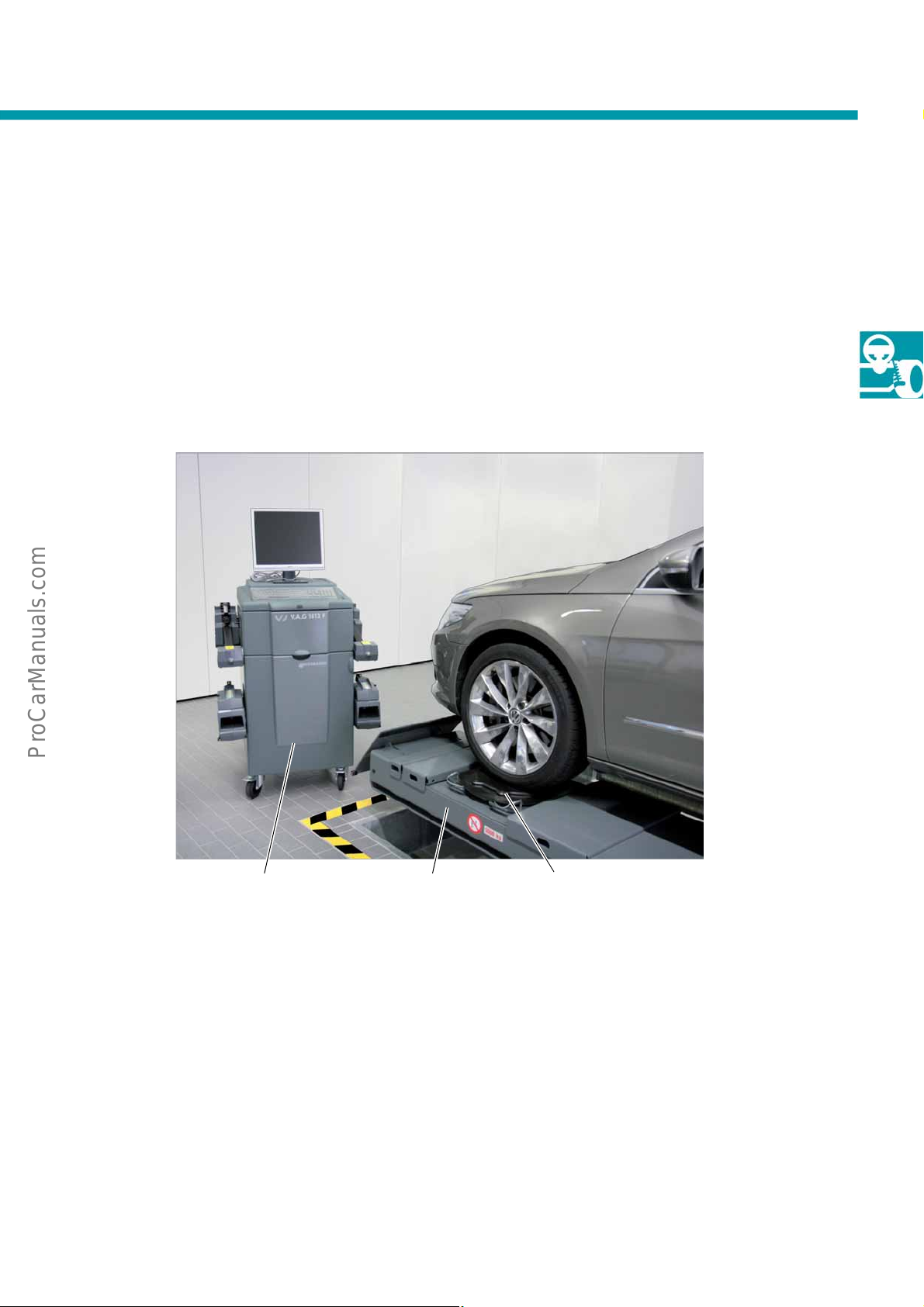
For precise wheel alignment, a corresponding
alignment system that is approved by Volkswagen
like, for example, the V.A.G 1813 F system from
Beissbarth, should be used.
However, we cannot look at all systems approved by
Volkswagen in this book. The following discussion
therefore describes wheel alignment using only a
computer-supported wheel alignment system as an
example.
Wheel alignment system/
wheel alignment computer
The system comprises the following main components
● Computer with monitor and corresponding alignment software
● Input devices like keyboard and remote control
● Output unit, for example, printer
● Sensors
● Clamps for sensors
Wheel alignment
platform
S448_044
Tur nt ab le
25
Page 26
Wheel Alignment
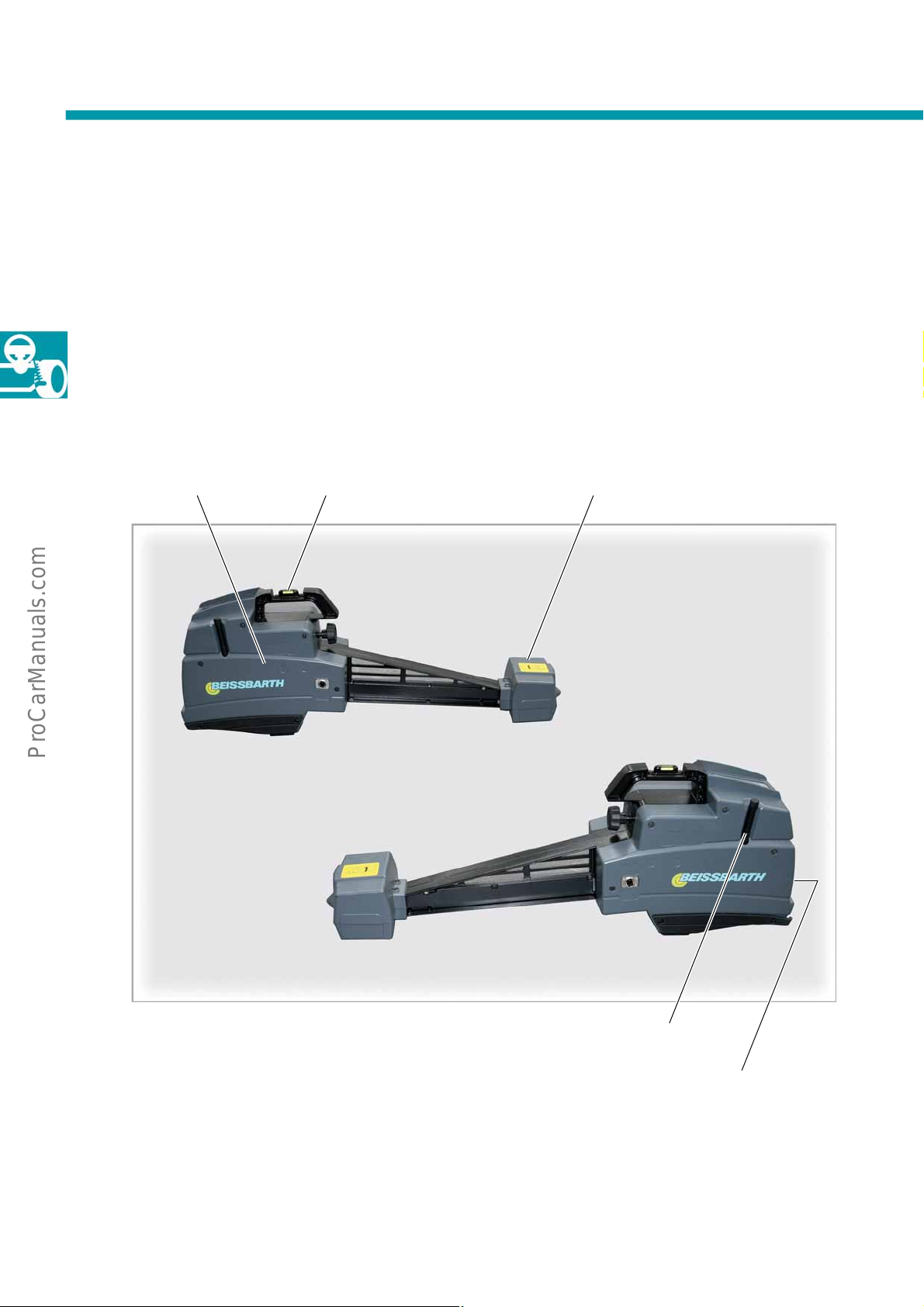
Sensors
The sensors work with rechargeable batteries or can be connected with power leads, if necessary. Each of the four
sensors is equipped with two CCD cameras that allow infrared measurements.
The measurement is made with an infrared light beam that is projected through a lens to a light mark. All
measurements on the horizontal plane are carried out with two transceiver CCD cameras that communicate with
each other.
The measurement data is transferred to the measuring box wirelessly.
Sensor
Spirit level
CCD camera
26
S448_050
The sensors form a closed measuring rectangle around the vehicle (see page 30).
Aerial
CCD camera
Page 27
Measuring unit bracket
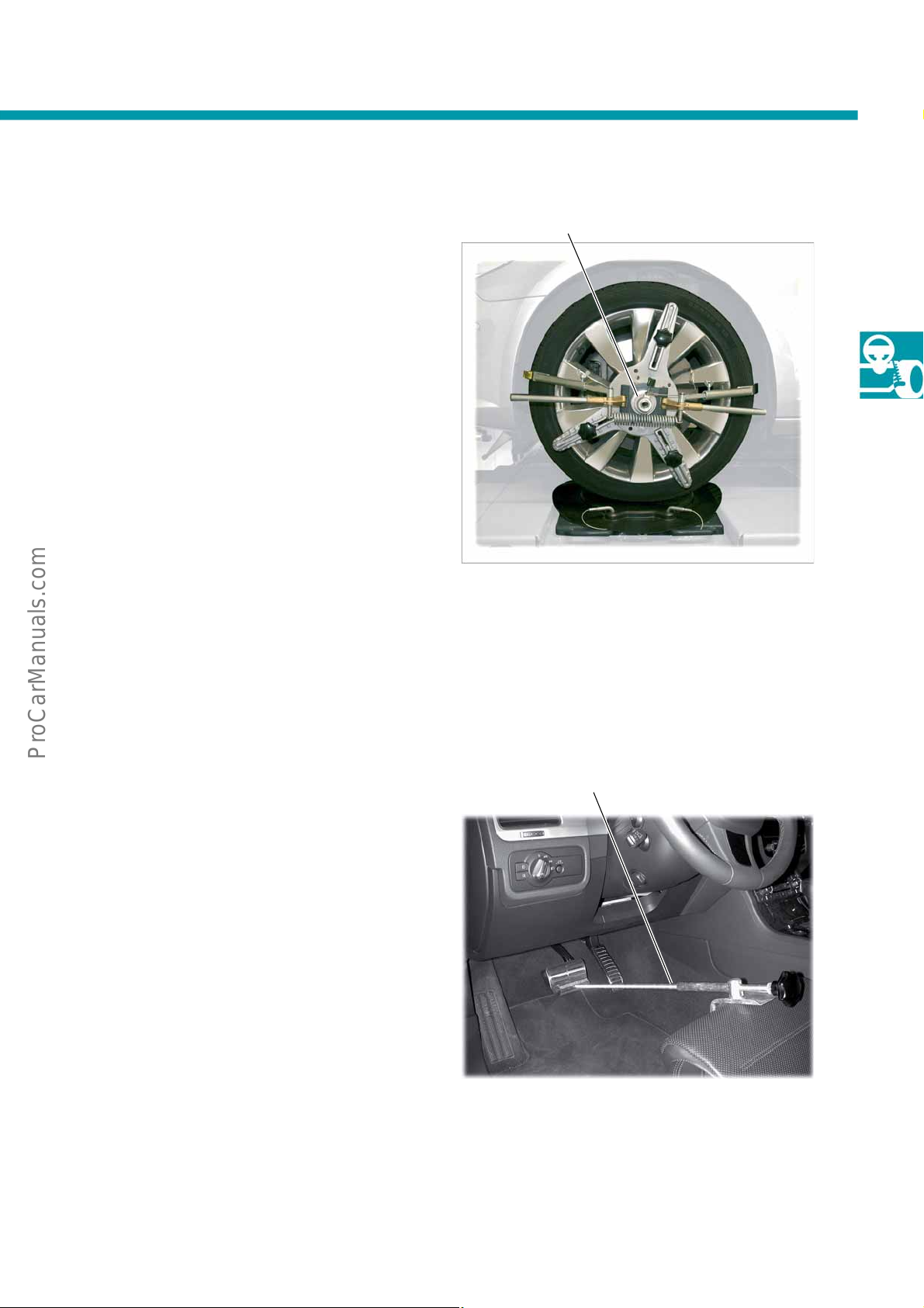
The measuring unit bracket is universally suitable for
wheels from 10 inches to 23 inches. The brackets on
the clamp simply fit onto the tyre tread.
The corresponding accessories, for example, plastic
sleeves, prevent damage to painted wheels or alloy
wheels.
Measuring unit bracket
S448_048
Brake pedal actuator
The brake pedal actuator prevents wheels rolling on
the turntables when the steering wheel is turned. This
is absolutely necessary to obtain precise caster,
steering axis inclination and track difference angle
measurements.
Brake pedal actuator
S448_114
27
Page 28
Wheel Alignment
Bases for wheels
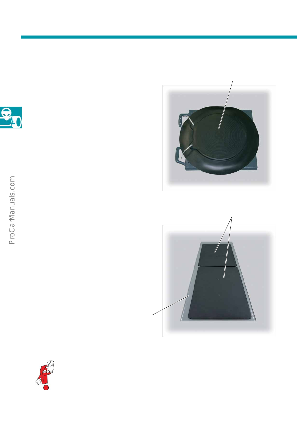
Turntable
The turntable can be ordered as an accessory for the
wheel alignment computer.
It allows the steering to be turned.
Sliding plate
Tur nt ab le
S448_038
Sliding plate
The sliding plate can be ordered as an accessory
for the wheel alignment computer.
The sliding plate allows wheel alignment to be
performed on vehicles with different wheelbases
without having to reposition the sliding plate.
The turntables and the sliding plates should be
unlocked after wheel rim run-out compensation.
Wheel alignment
platform
S448_039
28
Page 29
Wheel alignment software
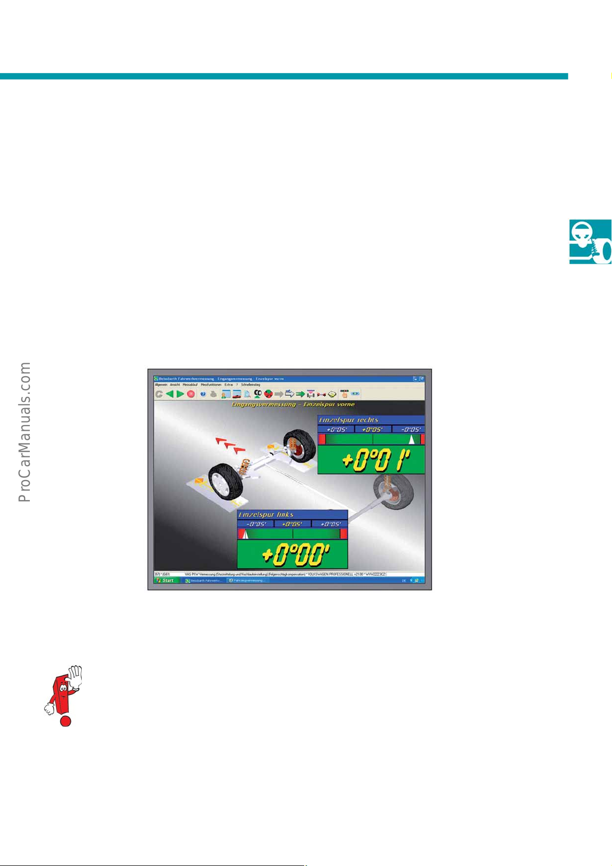
Once the preparations have been completed and the alignment system has been set up, you can start the wheel
alignment process.
The measurements are made in single steps with the aid of a dialog box on the computer screen.
The software has been specially developed for VW. It provides vehicle-specific measuring procedures and
information. It provides information on the adjustment procedures and contains alignment data for vehicles
throughout the Group.
The screenshot is only an example.
S448_054
29
Page 30
Wheel Alignment
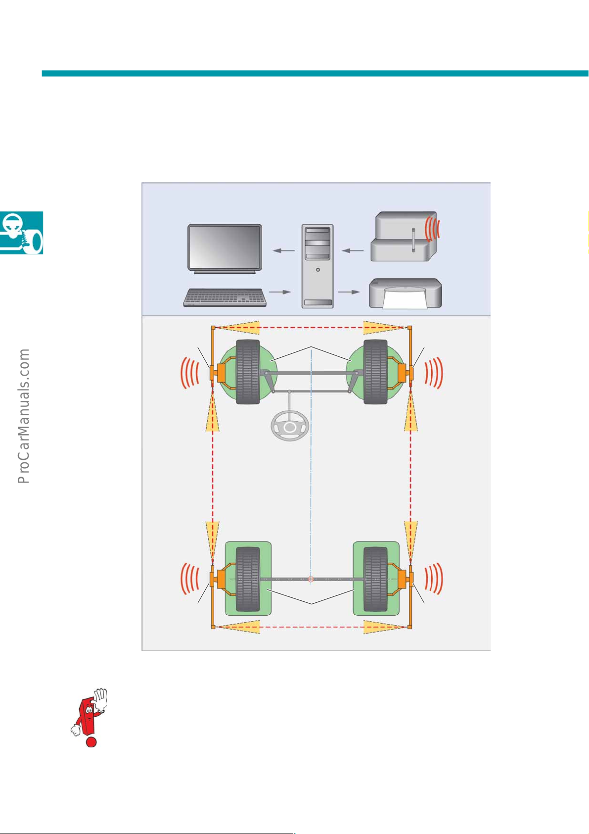
Wheel alignment system set-up
The illustration shows the communication paths of the wheel alignment system.
Monitor Computer
Keyboard
Measuring box
Printer
Sensor
Sensor Sensor
Tur nt ab le
Sliding plate
Sensor
30
Infrared light beam
S448_047
The infrared light beams emitted by the measuring
system may not be broken during the measurement.
Page 31
Carrying out the wheel alignment
The wheel alignment process allows the existing adjustment values (current state) to be compared with the
parameters specified by the vehicle manufacturer for the suspension.
Corrective adjustments can be made if there are impermissible deviations.
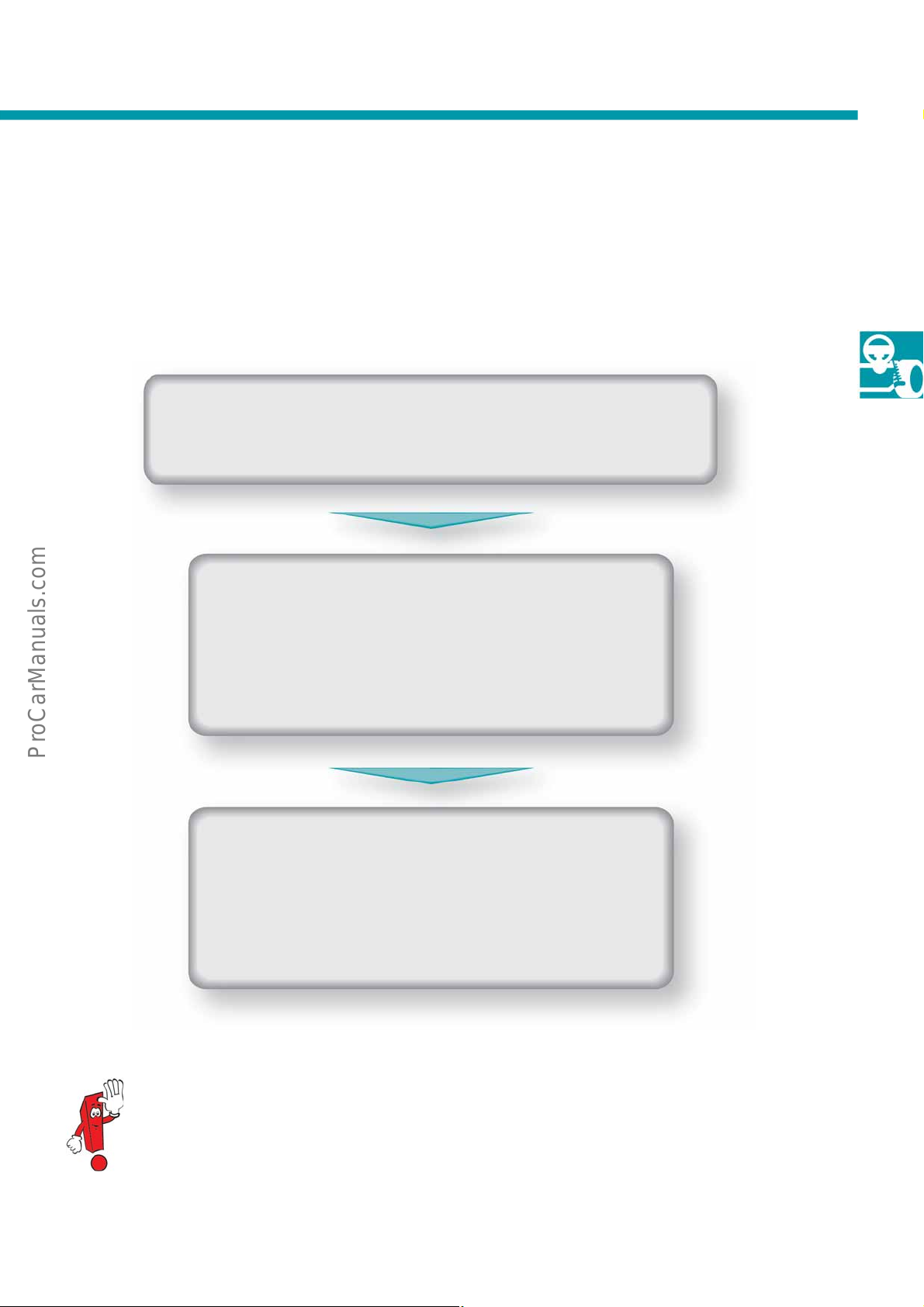
Procedure for wheel alignment
Preparation for wheel alignment
● Select vehicle type
● Create job order data
● Measure ride height
● Perform wheel rim run-out compensation
Wheel alignment process
● Initial measurement
● Corrective adjustments, if necessary
● Final measurement
● Alignment report
In the following descriptions, wheel alignment will be
explained using electronic alignment with a wheel
alignment computer.
S448_111
31
Page 32

Wheel Alignment
Preparations for wheel alignment
The following table provides an overview of the basic work steps to prepare for the wheel alignment.
Preparations for wheel alignment
Line up the turntables and sliding plates and adjust the lifting platform width for the track width and wheelbase of
the vehicle.
Drive the vehicle onto the turntables and sliding plates; the wheels must be in the centre of the turntables and plates.
Secure vehicle against rolling.
Test prerequisites:
Please observe the vehicle-specific information in the wheel alignment software.
● Check the general condition of the suspension and shock absorbers.
● Check that the wheel rims and tyres are the same size.
● Check the suspension, wheel bearings, steering and steering linkage checked for impermissible play and damage.
● The tread depth of the tyres on one axle may differ by a maximum of 2 mm.
● The inflation pressure of the tyres must comply with the specifications.
● The kerb weight of the vehicle must be observed.
● The fuel tank must be full. Fill it up if necessary.
● The spare wheel and vehicle tool set must be in the prescribed location in the vehicle.
● The water reservoir for the windscreen and headlight washer system must be full.
● Make sure that none of the sliding plates or turntables are at their end position during the alignment process.
● Alternatively, compensating weights can be used for missing liquids.
● The vehicle should be cool (e.g. Touareg/Phaeton with air suspension).
Attach the measuring unit brackets to the wheels.
The following criteria should be observed in particular:
● Sleeves should be used if necessary.
● Secure attachment of the measuring unit bracket
● Same attaching surface of measuring unit bracket
● Good form fit and positive engagement
32
Page 33
Settings for wheel alignment
Ride height
The ride height has a decisive influence on the results of the wheel alignment because the toe and camber readings
will be different if the ride height differs due to the suspension geometry.
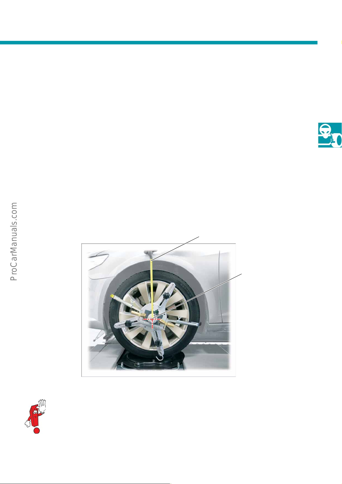
The ride height is determined by measuring vertically
from the centre of the wheel to the lower edge of the
wheel arch.
It is, however, also possible to measure the distance
from the lower edge of the wheel arch to the rim
flange and then add half of the wheel rim diameter
(the wheel rim diameter must be measured).
This method is recommended as the centre of the
wheel could be obscured by parts of the measuring
equipment, for example, the quick clamp units.
The ride height can be varied by changing the load,
which also changes the readings for the suspension.
The vehicle should therefore have the correct kerb
weight before the wheel alignment is started.
Lower edge of wheel arch
Measuring tool
fitted on centre of wheel
You must make sure that the ride height is within the tolerance
range specified by the manufacturer.
If the tank is not completely filled with fuel, changes to the toe,
camber and caster readings will result.
S448_051
33
Page 34

Wheel Alignment
Wheel rim run-out compensation
Wheel rim run-out compensation must be carried out.
This measures the lateral run-out of the wheel and the
clamping errors of the measuring unit bracket in one
revolution of the wheel and compensates the toe and
camber readings.
The wheels must be lifted off the ground to perform
the wheel rim run-out compensation. Loosen the
securing screw on the sensor so that the rotational
angle sender flanged onto the pin can measure the
wheel position.
S448_052
After the wheel rim run-out compensation has been
started, the wheel should be turned one quarter of a
revolution three times in the direction of travel in
accordance with the user guide on the screen.
The following work is also necessary after the
wheel rim run-out compensation and before the initial
measurement
● Pull out the locking pins from the turntables under
the wheels to prevent tension in the suspension
● Lower the vehicle
● Rock the vehicle at the front and rear axle so that
the suspension settles in a stable central position
● Lock the brakes by fitting the brake pedal actuator
S448_053
The vehicle should be lowered onto the
centres of the turntables and sliding
plates.
34
The screens shown over the following
pages are purely examples.
Page 35
Initial measurement
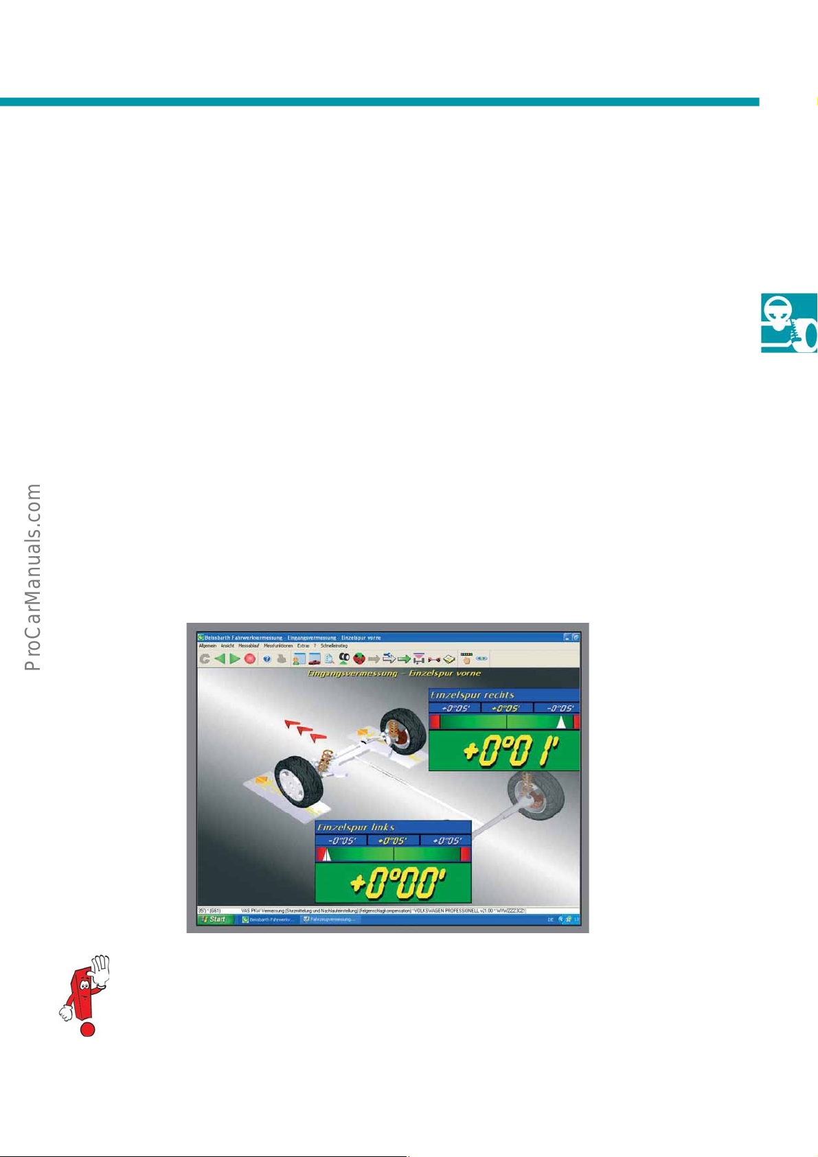
The initial measurement should basically be carried out with the following steps:
● Set wheels to straight-ahead
● Align spirit level on sensors
● Measure the rear axle values
● Perform steering routine by turning wheels to 20°
on both sides in order to determine caster, steering
axis inclination and toe-out on turns.
Return steering wheel to straight ahead position.
● Measure toe and camber of front axle
● Perform steering routine for measuring maximum
left/right steering angle
● Overview of readings with specified/current value
comparison. If all readings are within the
permitted tolerances, an alignment report can be
printed out immediately and the wheel alignment
can be ended on this vehicle.
● If the current readings are outside the tolerance
range, adjustments are required. All values that
can be adjusted on the vehicle are indicated by
a tool icon during the adjustment work.
Corresponding adjustment diagrams and
information can be displayed on the screen for
these readings at the touch of a button.
Due to possible changes and updates, the instructions in ELSA
(electronic service information system) should be observed
during the preparation and performance of the wheel
alignment.
S448_073
35
Page 36
Wheel Alignment
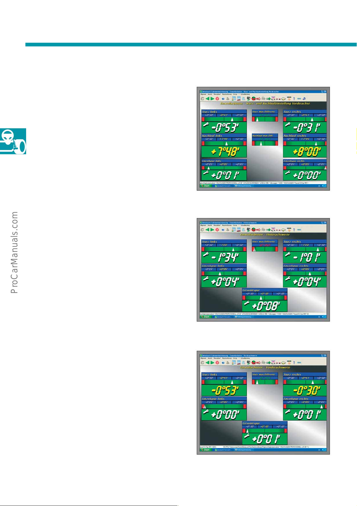
Adjustment work – camber and caster
setting on front axle
The following can be set:
● Left camber
● Left caster
● Left toe
● Right camber
● Right caster
● Right toe
● Camber difference
● Caster difference
Adjustment work – rear axle settings
The following can be set:
● Left camber
● Right camber
● Left toe
● Right toe
● Tota l toe
● Camber difference
On torsion beam axles like, for example, on the Polo,
individual adjustments cannot be made. The readings
can be averaged out by shifting the axle.
Adjustment work – front axle settings
The following can be set:
S448_056
S448_057
36
● Left camber
● Right camber
● Left toe
● Right toe
● Tota l toe
S448_059
Page 37
Final measurement
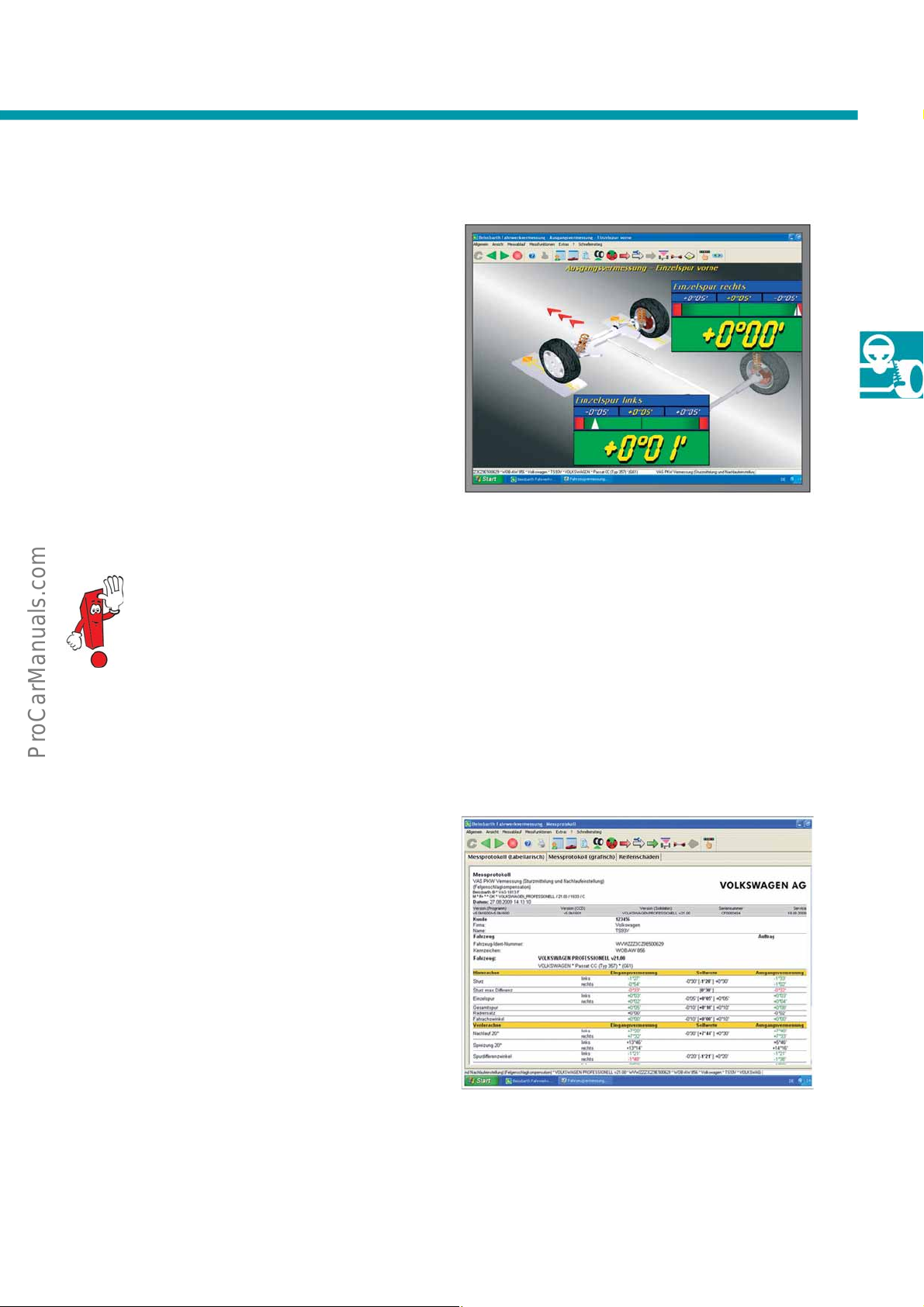
The final measurement should be carried out in the
same way as the initial measurement.
The alignment report is displayed at the end of the
final measurement.
If all readings from the final measurement are within
the permitted tolerances, an alignment report can
then be printed and the wheel alignment can be
ended on this vehicle.
Before the final measurement, all loosened screw connections
on the axles should be tightened to the specified torques.
S448_061
Alignment report
The customer and vehicle data is shown at the top of
the alignment report.
In the lower section, you will see the specified data
related to the readings from the initial and final
measurement.
S448_072
37
Page 38
Using Wheel Alignment Stands for Other Systems
Driver assistance systems
Driver assistance systems provide physical and psychological support for the driver.
As ever, the driver is solely responsible for his vehicle and its performance.
Lane departure warning system
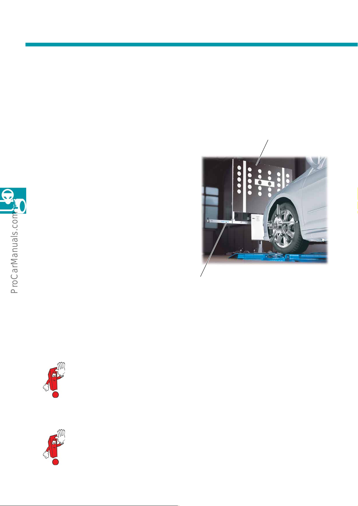
If a vehicle is equipped with the lane departure
warning system, the system’s camera may need to be
re-calibrated after wheel alignment.
This is absolutely necessary if the toe or camber of the
rear axle has been adjusted.
Adjusting the settings on the rear axle also changes
the thrust axis of the vehicle.
The setting device VAS 6430 is used to calibrate the
warning system camera. It is positioned in front of the
vehicle at a right angle to the thrust axis with the help
of the wheel alignment system.
The setting device comprises different components
and is also used to calibrate the ACC system, for
example.
Calibration board for warning system – VAS 6430/4
S448_105
Setting device VAS 6430/1
38
The steps for the calibration process are listed in the wheel alignment
computer software.
You will find detailed information on the warning system in self-study
programme no. 418 “The Lane Departure Warning System”.
Page 39
Adaptive Cruise Control – ACC
If the vehicle is equipped with the adaptive cruise
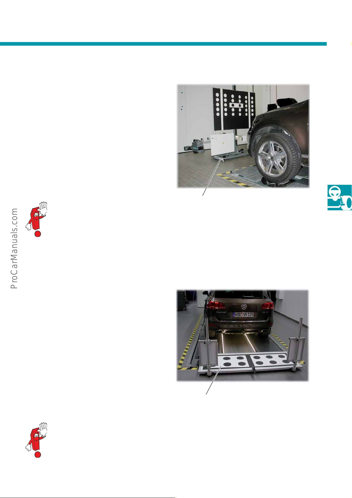
control system (ACC), the radar sensors used by the
system may need to be re-calibrated after wheel
alignment.
This is absolutely necessary if the rear axle toe has
been adjusted during the wheel alignment. You will
need the setting device VAS 6430 to calibrate the
radar sensor.
You will find detailed information on the adaptive
cruise control system in self-study programme no. 470
“The Touareg 2011 Electrical/Electronics System”.
S448_115
Setting device VAS 6430
Rear view camera –
reversing camera system
If a vehicle is equipped with the rear view system, the
system’s camera will need to be re-calibrated if the
toe or camber settings of the rear axle have been
adjusted during wheel alignment.
The calibration unit VAS 6350 is used to calibrate the
rear view camera.
Adjusting the settings on the rear axle also changes
the thrust axis of the vehicle. The optimum scanning
area of the rear view camera depends on the thrust
axis.
You will find detailed information on the reversing camera system
in self-study programme. 407 “Reversing Camera System”.
S448_116
Calibration unit VAS 6350
39
Page 40
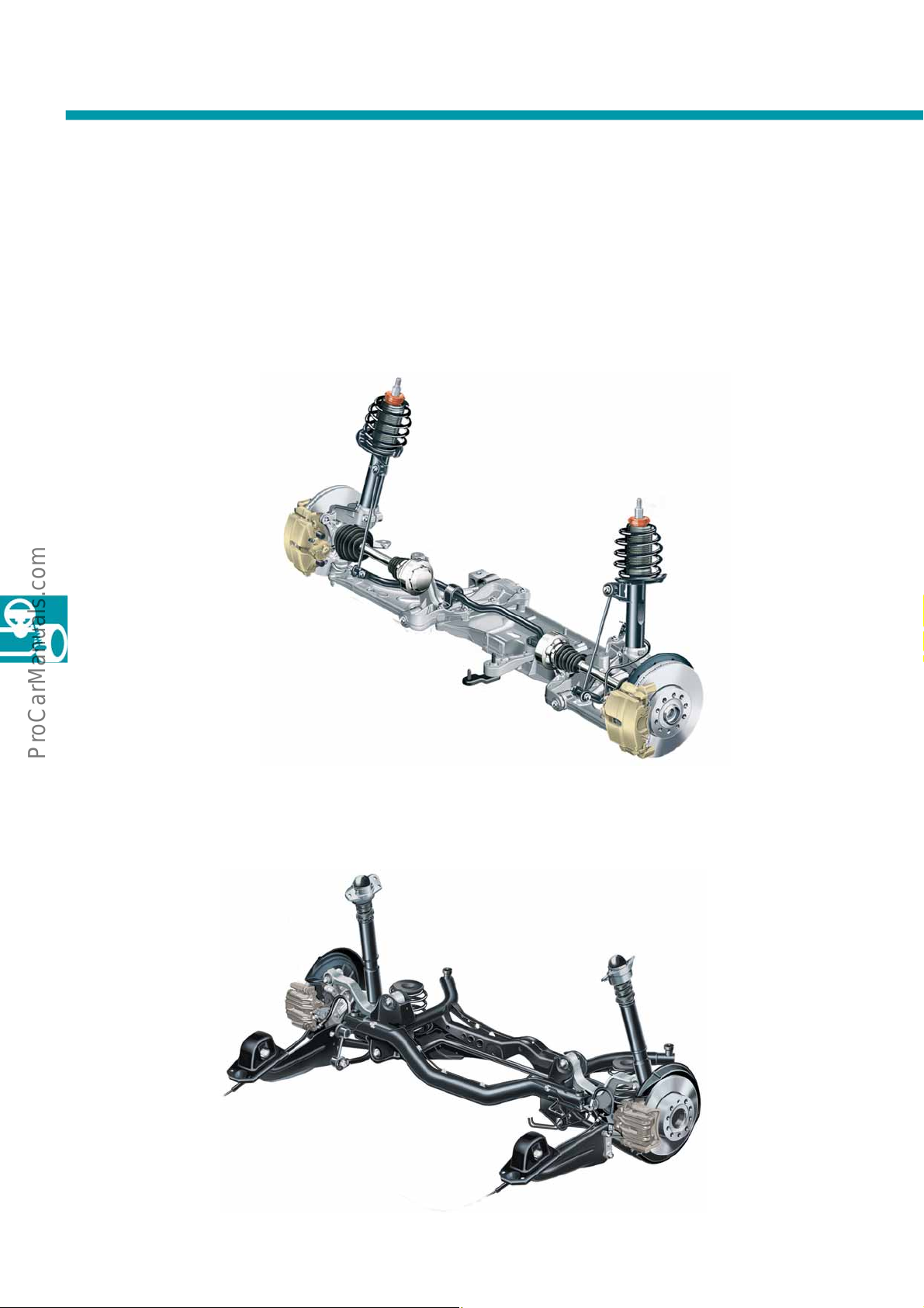
Axles
Types of axle
The following are some examples of the types of axle used by Volkswagen.
McPherson strut front suspension on Golf 2004
● Toe adjustable
● Camber not adjustable, can be influenced by centring the axle
Four-link rear axle on Golf 2004
● Toe and camber separately adjustable
S448_006
S448_007
40
Page 41
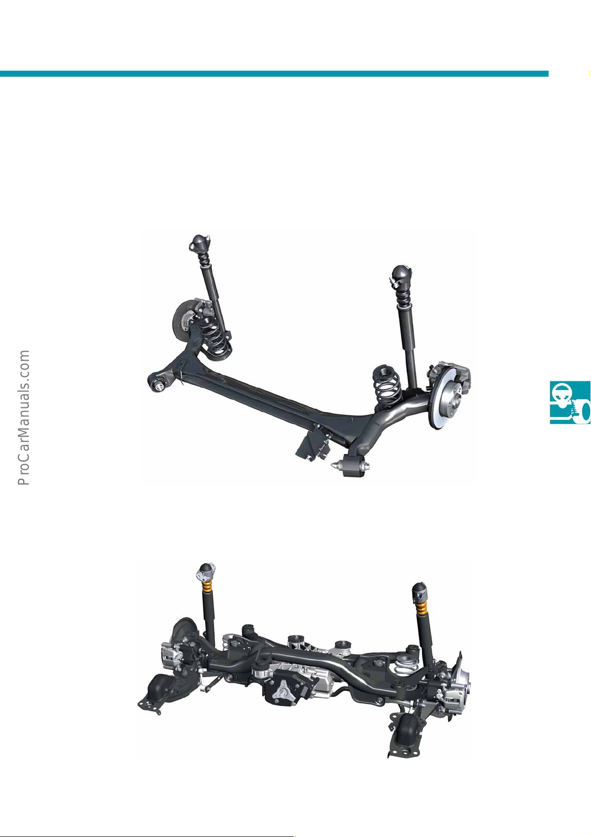
Torsion-beam rear axle on Polo 2010
● Cannot be adjusted
● Can only be centred
Four-link 4motion rear axle on Passat and Tiguan
● Toe and camber separately adjustable
S448_070
S448_069
41
Page 42
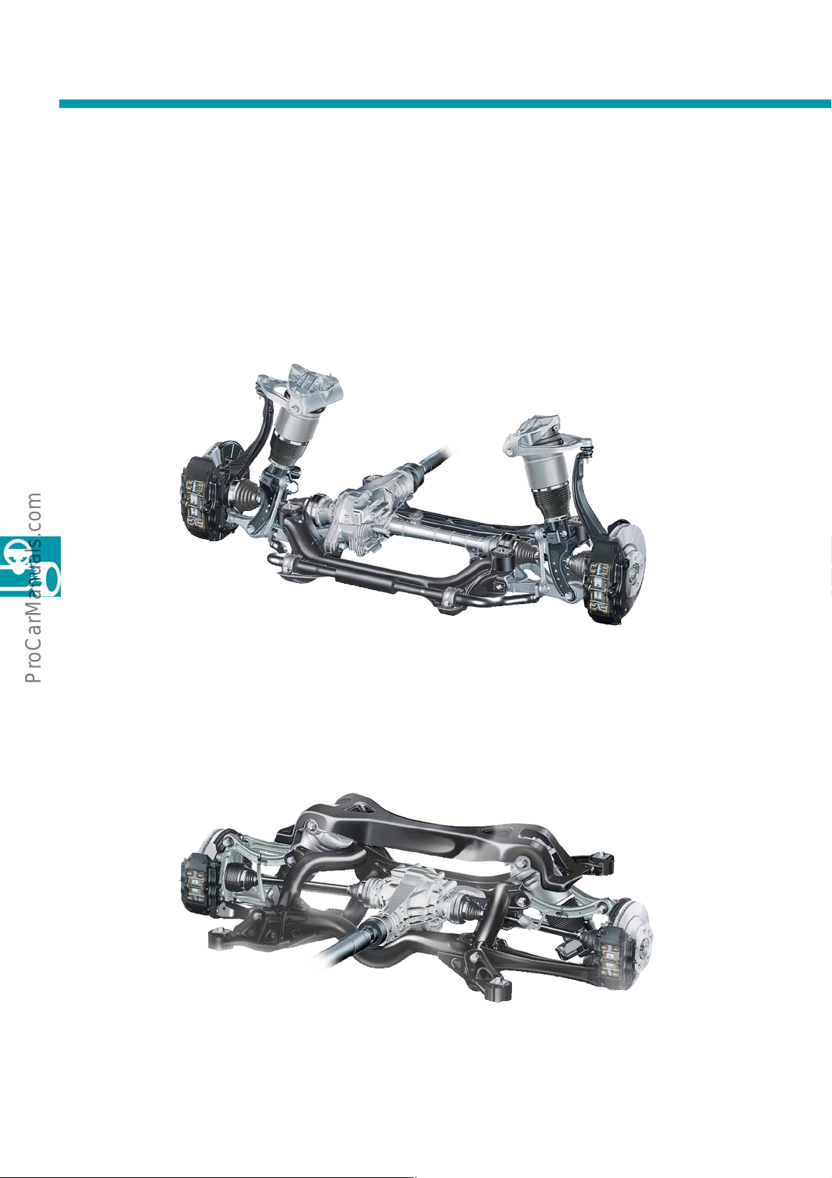
Axles
Steel-spring suspension or air suspension on Touareg
The Touareg can be equipped either with a steel-spring suspension system or an air suspension system.
The illustrations show the version with air suspension.
Front axle
● Toe, camber and caster separately adjustable
Rear axle
● Toe and camber separately adjustable
S448_008
S448_106
42
Page 43
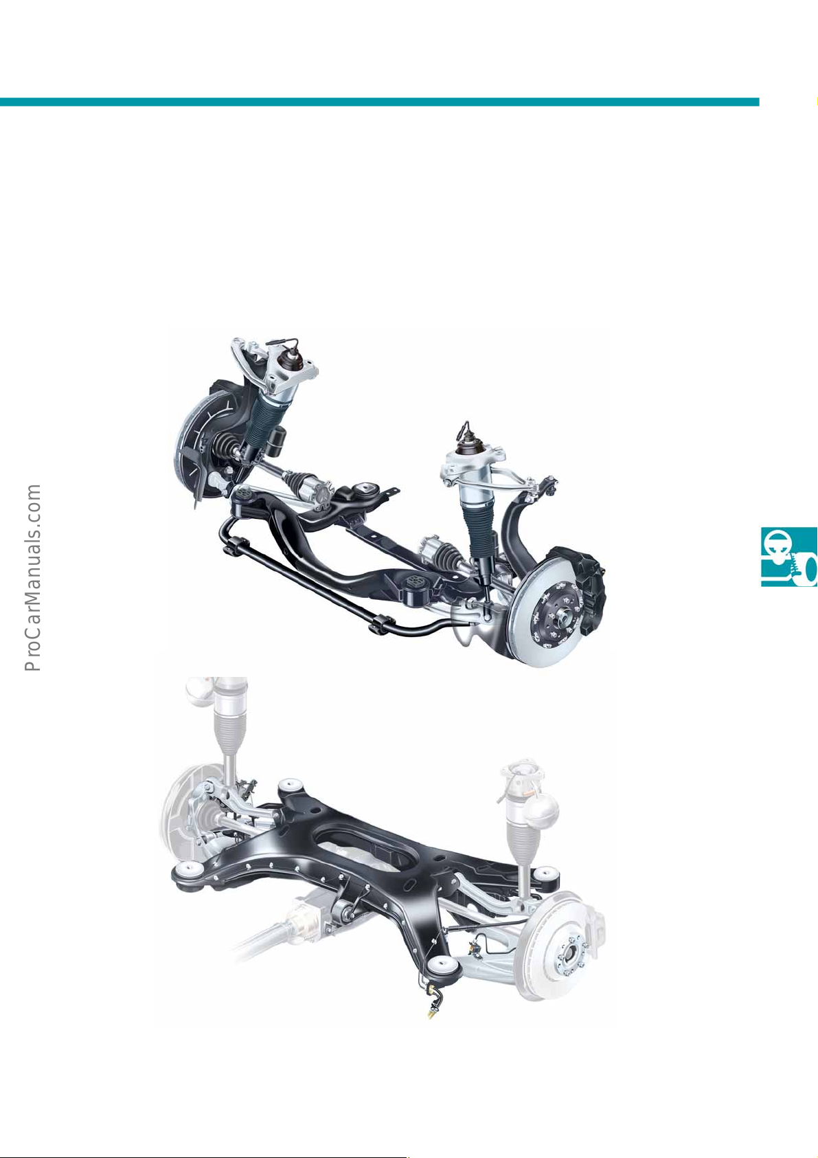
Steel-spring suspension or air suspension on Phaeton
The Phaeton can be equipped either with a steel-spring suspension system or an air suspension system.
The illustrations show the version with air suspension.
Front axle
● Toe, camber and caster separately adjustable
Rear axle
● Toe and camber separately adjustable
S448_009
S448_107
43
Page 44
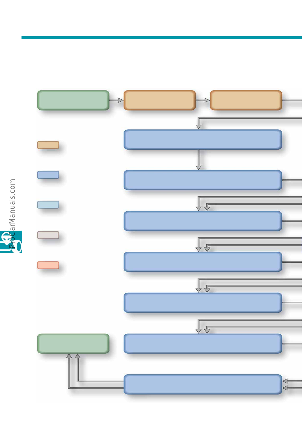
Flowchart
Flowchart for wheel alignment
(using example of Golf 2009)
Start
Preparation of
wheel alignment
Measuring procedure
Comparison of specified
and current values
Correction/adjustment
Select vehicle
Create job order data
Initial measurement
Check camber of
Measure
ride height
front axle
Check toe of
front axle
IMPORTANT
End
Check camber of
rear axle
Check toe of
rear axle
Check toe of
front axle
Final measurement
44
Page 45
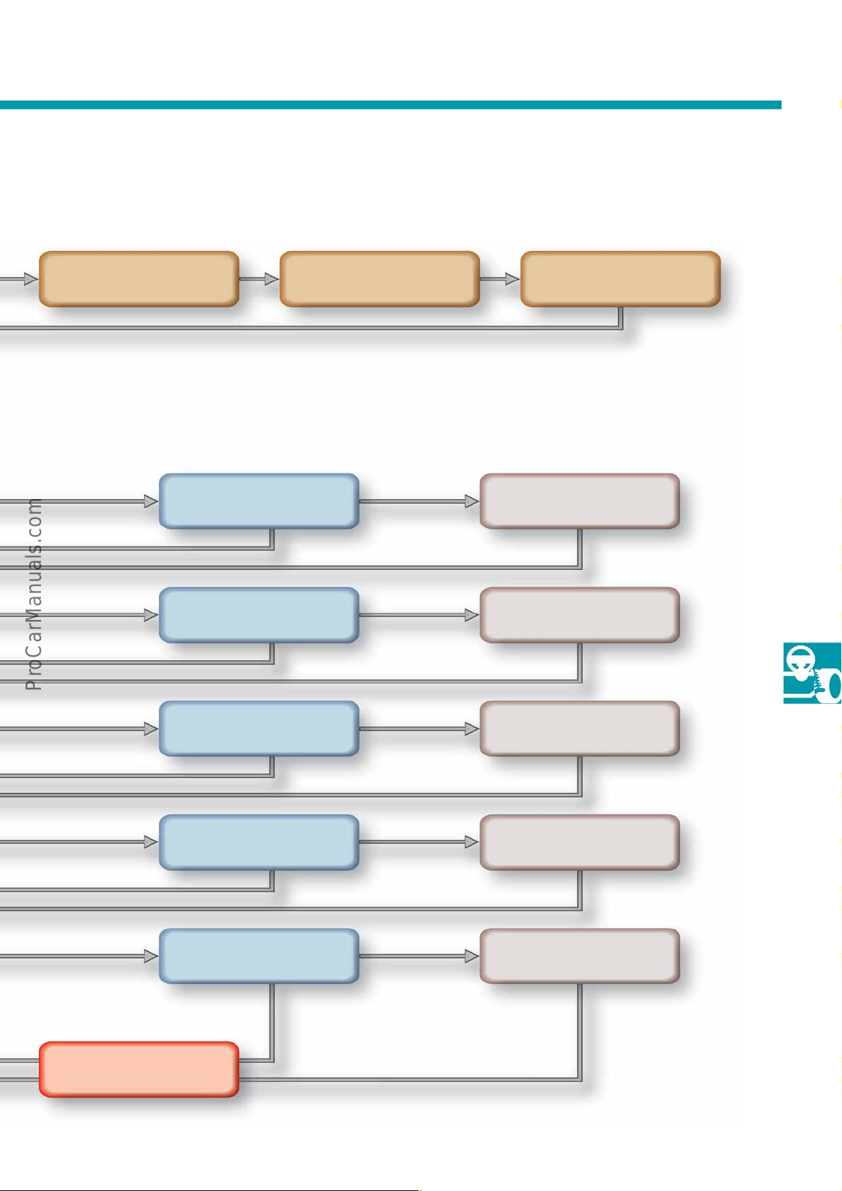
Perform wheel rim run-out
compensation
Rock
vehicle
Fit brake pedal
actuator
Current reading
within tolerance?
Ye s
Current reading
within tolerance?
Ye s
Current reading
within tolerance?
Ye s
Current reading
within tolerance?
Ye s
No
No
No
No
Adjust
camber
Adjust
toe
Adjust
camber
Adjust
toe
Current reading
within tolerance?
Tighten screw connections
to specified torque
Ye s
No
Adjust
toe
S448_110
45
Page 46

Notes
46
Page 47

47
Page 48
448
© VOLKSWAGEN AG, Wolfsburg
All rights and rights to make technical alterations reserved.
000.2812.28.20 Technical status 02.2011
Vol ksw agen AG
Service Training VSQ-1
Brieffach 1995
38436 Wolfsburg
❀ This paper was manufactured from pulp that was bleached without the use of chlorine.
 Loading...