


05TA
TUBE-ICE® MACHINE
(Includes model P118F/HE100)
Manual Part Number 12A4171M06
Revision 3
Service Manual
$5000
NOTICE
This manual is the property of the owner of this particular Tube-Ice® machine.
Model #____________________ Serial #____________________.
It is to be left on the premises with this machine at all times. After start-up, it should be stored in a safe place where it can be readily available when needed for future reference in maintaining troubleshooting or servicing.
Failure to comply with this notice will result in unnecessary inconvenience and possible additional expenses.
This manual is intended as an informational tool for the installation, operation, maintenance, troubleshooting, and servicing of this equipment. If an existing situation calls for additional information not found herein, we suggest that you contact your distributor first. If further assistance or information is needed, please feel free to contact the factory at 502-635- 3000 or FAX at 502-635-3024.
IMPORTANT: To activate the machine warranty, the Product Registration Form MUST be completed and returned to the factory promptly after the official start-up. Product Registration Form is located in the Owners Packet or can be found online at www.vogtice.com/registration.htm.
Please return to: |
VOGT ICE , LLC |
|
Suite #19 |
|
1000 W. Ormsby Ave. |
|
Louisville, KY 40210 |

VOGT ICE , LLC, located in
Louisville, Kentucky since 1880.
Sales - (800) 853-8648
Service - (502) 635-3000
Parts - Your Local Distributor
Call your local distributor first for all of your parts and service needs.
Since 1880, Manufacturers of Quality
Tube-Ice® Machines
Vogt
Tube-Ice Machines
Installation, Service Manual and Parts Catalog #12A4171M06
05TA Model
05TA Service Manual |
i |
|
TABLE OF CONTENTS
TABLE OF CONTENTS
Vogt® TUBE-ICE® MACHINES
Model 05TA (P118F)
|
Page No. |
1. INTRODUCTION |
|
A Brief History Of Our Company.................................................................................................................................. |
1-1 |
Vogt Energy-Savings Tube-Ice® Machines .................................................................................................................. |
1-1 |
Preview ..................................................................................................................................................................... |
1-1 |
Important Safety Notice................................................................................................................................................. |
1-2 |
Special Precautions To Be Observed When Charging Refrigeration Systems............................................................... |
1-2 |
Safety Symbols and What They Mean ........................................................................................................................... |
1-3 |
Assembly Drawing Model 05TA (P118F) Air-Cooled, FIGURES 1-1, 1-2, & 1-3....................................................... |
1-4, 1-5, 1-6 |
Assembly Drawing Model 05TA (P118F) Water Cooled, FIGURES 1-4, 1-5, & 1-6 .................................................. |
1-7, 1-8, 1-9 |
2. RECEIPT OF YOUR TUBE-ICE MACHINE |
|
Inspection ..................................................................................................................................................................... |
2-1 |
Safety Valves ................................................................................................................................................................. |
2-1 |
Machine Room .............................................................................................................................................................. |
2-1 |
Storage (prior to installation and start-up) ..................................................................................................................... |
2-2 |
Vogt Model Nomenclature, FIGURE 2-1...................................................................................................................... |
2-2 |
3. INSTALLING YOUR TUBE-ICE MACHINE |
|
Water Supply and Drain Sizes, TABLE 3-1 .................................................................................................................. |
3-1 |
Cooling Tower ............................................................................................................................................................... |
3-2 |
Space Diagram (Air-Cooled Machine), FIGURE 3-2A ................................................................................................. |
3-3 |
Space Diagram (Water Cooled Machine), FIGURE 3-2B ............................................................................................. |
3-4 |
Control Panel Power Connections FIGURE 3-3 ........................................................................................................... |
3-5 |
Electrical Specifications, TABLE 3-2 ........................................................................................................................... |
3-5 |
Phase Check, Voltage and Current unbalance ............................................................................................................... |
3-6 |
Rotation Check .............................................................................................................................................................. |
3-6 |
Air-Cooled Condenser Installation Instructions ............................................................................................................ |
3-7 |
Pounds of R-22/404A to Add Vs. Liquid Line Length, TABLE 3-3 ............................................................................. |
3-8 |
Air-Cooled Condenser Data, TABLE 3-4...................................................................................................................... |
3-9 |
Condenser Dimensions, FIGURE 3-4............................................................................................................................ |
3-10 |
Condenser Field Piping (Cold Weather Valve Kit), FIGURE 3-5................................................................................. |
3-10 |
Condenser Equivalent Line Size Worksheet.................................................................................................................. |
3-11 |
Equivalent Feet Due To Friction, TABLE 3-5............................................................................................................... |
3-11 |
Minimum Traps For Discharge Lines, FIGURE 3-6 ..................................................................................................... |
3-11 |
Wiring For DD-311 and DD-361 Condensers (3 phase motors), FIGURE 3-7 ............................................................. |
3-12 |
Rota-lock Connector Torque Ratings, TABLE 3-6 ....................................................................................................... |
3-12 |
Ice Bin Thermostat Sensor............................................................................................................................................. |
3-13 |
Typical Bin Sensor Mounting, FIGURE 3-8 ................................................................................................................. |
3-13 |
ii
05TA Service Manual
TABLE OF CONTENTS
|
Page No. |
3. INSTALLING YOUR TUBE-ICE MACHINE (Cont.) |
|
Programming Electronic Bin Thermostat FIGURE 3-9 ................................................................................................. |
3-14 |
Installation Review: A Checklist .................................................................................................................................. |
3-15 |
4. HOW YOUR TUBE-ICE MACHINE WORKS |
|
Principle of Operation ................................................................................................................................................... |
4-1 |
Freeze Period ................................................................................................................................................................. |
4-2 |
Harvest Period ............................................................................................................................................................... |
4-2 |
Piping Nomenclature TABLE 4-1 ................................................................................................................................. |
4-2 |
Water Cooled Piping Schematic, FIGURE 4-1.............................................................................................................. |
4-3 |
Air-Cooled Piping Schematic, FIGURE 4-2.................................................................................................................. |
4-4 |
5. START-UP AND OPERATION |
|
Refrigeration System Review ........................................................................................................................................ |
5-1 |
Refrigerant Charge......................................................................................................................................................... |
5-1 |
Start-up Checklist .......................................................................................................................................................... |
5-2 |
Control Panel Switch Layout, FIGURE 5-1 .................................................................................................................. |
5-3 |
Start-up Procedure ........................................................................................................................................................ |
5-3 |
Adding Refrigerant ........................................................................................................................................................ |
5-4 |
Operating Tips ............................................................................................................................................................... |
5-5 |
6. ELECTRICAL CONTROLS
Control Panel, FIGURE 6-1…………………………………………………………………………………………….6-1
Control Panel Components (Standard), FIGURE 6-2.................................................................................................... |
6-2 |
Control Panel Door w/Power monitor option (Standard), FIGURE 6-2A ..................................................................... |
6-3 |
Control Panel Components (CE & Australian approval), FIGURE 6-2B...................................................................... |
6-4 |
Control Panel Components and Part Numbers, TABLE 6-1 ......................................................................................... |
6-5 |
Description of Control Panel Component Function, TABLE 6-2.................................................................................. |
6-6 |
Electrical Schematic All Voltages 50-60 Hz. All Voltages, FIGURE 6-3 ..................................................................... |
6-7 |
Copeland Compressor Overload Module Wiring Diagram, FIGURE 6-4 ..................................................................... |
6-8 |
7. MAINTENANCE |
|
Ice-Making Section........................................................................................................................................................ |
7-1 |
Cleaning Procedure........................................................................................................................................................ |
7-1 |
Sanitizing Procedure...................................................................................................................................................... |
7-2 |
Water Distributors ......................................................................................................................................................... |
7-3 |
Number of Water Distributors Per Tube Size, TABLE 7-1 ........................................................................................... |
7-3 |
Water Tank .................................................................................................................................................................... |
7-3 |
Water Cooled Condensers ............................................................................................................................................. |
7-3 |
Water Cooled Condensers, Checking Operation ........................................................................................................... |
7-3 |
Water Cooled Condensers, Draining ............................................................................................................................. |
7-4 |
Water Cooled Condensers, Chemical Cleaning ............................................................................................................. |
7-5 |
Water Cooled Condensers, Mechanical Cleaning.......................................................................................................... |
7-5,7-6 |
Lubrication .................................................................................................................................................................... |
7-6 |
05TA Service Manual |
iii |
|
TABLE OF CONTENTS
Page No.
7. MAINTENANCE (Cont.) |
|
Lubrication, Compressor, FIGURE 7-1 ………………………………………………………………………… |
7-6 |
Compressor Recommended Lubricants, TABLE 7-2 …………………………………………………………… |
7-6 |
Compressor Oil Capacity Table7-3 ………………………………………………………………………………… |
7-7 |
Cutter Gear Reducer Lubrication, FIGURE 7-2 ........................................................................................................... |
7-7 |
Preventive Maintenance................................................................................................................................................... |
7-8, 7-9 |
Preventive Maintenance Program .................................................................................................................................... |
7-10 |
8. TROUBLESHOOTING |
|
List Of Symptoms ............................................................................................................................................................ |
8-1 |
Machine Won’t Run ........................................................................................................................................................ |
8-2, 8-3 |
Freeze-Up Due To Extended Freezing Period ................................................................................................................. |
8-4 |
Freeze-Up Due To Ice Failing To Discharge ................................................................................................................... |
8-5 |
Low Ice Capacity ............................................................................................................................................................. |
8-6 |
Low Compressor Oil Level.............................................................................................................................................. |
8-7 |
Poor Ice Quality............................................................................................................................................................... |
8-8 |
High Head Pressure (Water Cooled)................................................................................................................................ |
8-9 |
High Head Pressure (Air-Cooled).................................................................................................................................... |
8-10 |
9. SERVICE OPERATIONS |
|
Adjustable Blowdown (For Clearer Ice) FIGURE 9-1 .................................................................................................... |
9-1 |
Automatic Blowdown (Harvest Cycle) ............................................................................................................................ |
9-1 |
Float Valve (Make-Up Water) ......................................................................................................................................... |
9-1 |
Float Switch..................................................................................................................................................................... |
9-2 |
Hansen Refrigerant Float Switch, FIGURE 9-2............................................................................................................... |
9-2 |
Hand Expansion Valve .................................................................................................................................................... |
9-3 |
Freezer Pressure Switch................................................................................................................................................... |
9-3 |
Freezer Pressure Switch (Allen-Bradley), FIGURE 9-3 .................................................................................................. |
9-3 |
High/Low Pressure Switch .............................................................................................................................................. |
9-4 |
High/Low Pressure Switch, FIGURE 9-4 ........................................................................................................................ |
9-4 |
Head Pressure .................................................................................................................................................................. |
9-4 |
Water Cooled Units ......................................................................................................................................................... |
9-4 |
Air-Cooled Units ............................................................................................................................................................. |
9-5 |
Water Regulating Valve, FIGURE 9-5A ......................................................................................................................... |
9-5 |
Condenser Fan Switch, FIGURE 9-5B ............................................................................................................................ |
9-5 |
Solenoid Valves............................................................................................................................................................... |
9-5 |
“X” Solenoid Valve, FIGURE 9-6A & 9-6B................................................................................................................... |
9-6 |
“D” Solenoid Valve, FIGURE 9-7A................................................................................................................................ |
9-7 |
“A” Solenoid Valve, FIGURE 9-7B ................................................................................................................................ |
9-7 |
Oil Separator.................................................................................................................................................................... |
9-8 |
Oil Separator, FIGURE 9-8 ............................................................................................................................................. |
9-8 |
Compressor Crankcase Heater ......................................................................................................................................... |
9-8 |
Copeland Discus Compressor, FIGURE 9-9 ................................................................................................................... |
9-8 |
Compressor Motor Protection, Electronic ....................................................................................................................... |
9-9 |
iv
05TA Service Manual
TABLE OF CONTENTS
|
Page No |
9. SERVICE OPERATIONS (Cont.) |
|
High Potential Testing .................................................................................................................................................... |
9-10 |
Field Troubleshooting...................................................................................................................................................... |
9-11 |
Sentronic Oil Pressure Safety Control FIGURE 9-11...................................................................................................... |
9-12 |
Sentronic Oil Pressure Sensor ......................................................................................................................................... |
9-13 |
Sentronic Oil Pressure Module........................................................................................................................................ |
9-13 |
CoreSense Protection Module ......................................................................................................................................... |
9-13 |
CoreSense Protection Faults and wiring FIGURE 9-11A................................................................................................ |
9-14 |
Circulating Water Pump Motor ....................................................................................................................................... |
9-15 |
Water Pump, FIGURE 9-12............................................................................................................................................. |
9-15 |
Cutter Gear Reducer ........................................................................................................................................................ |
9-15 |
Gear Reducer, FIGURE 9-13........................................................................................................................................... |
9-15 |
Thawing Timer, FIGURE 9-14A ..................................................................................................................................... |
9-16 |
Thawing Timer Wiring, FIGURE 9-14B ......................................................................................................................... |
9-16 |
Condenser Cleaning......................................................................................................................................................... |
9-17 |
Air-Cooled Condenser ..................................................................................................................................................... |
9-17 |
Pump Down ..................................................................................................................................................................... |
9-17 |
Removal Of Refrigerant From Machine .......................................................................................................................... |
9-18 |
Refrigerant Leaks............................................................................................................................................................. |
9-18 |
Non-Condensable Gases .................................................................................................................................................. |
9-18 |
Compressor Motor Burnout ............................................................................................................................................. |
9-19 |
Capacity Control Valve (Compressor Unloader) ............................................................................................................. |
9-20 |
Copeland Compressor Unloader Valve, FIGURE 9-15 ................................................................................................... |
9-20 |
Loaded Operation (Freeze Period)................................................................................................................................... |
9-20 |
Unloaded Operation (During Thaw Only) ....................................................................................................................... |
9-20 |
Cutter Motor .................................................................................................................................................................... |
9-21 |
Cutter Gear Reducer ........................................................................................................................................................ |
9-21 |
Water Tank Removal ....................................................................................................................................................... |
9-22 |
Cutter & Bearing Removal/Installation ........................................................................................................................... |
9-22 |
Cutter Assembly, FIGURE 9-16 ...................................................................................................................................... |
9-23 |
Cutter Drive Parts, FIGURE 9-17.................................................................................................................................... |
9-23 |
Cutter Parts (Cylinder Ice), FIGURE 9-18A.................................................................................................................... |
9-24 |
Cutter Parts (Crushed Ice), FIGURE 9-18B .................................................................................................................... |
9-25 |
Crushed Ice Production ................................................................................................................................................... |
9-25 |
Defrost Pressure Switch (DPS), FIGURE 9-19 ............................................................................................................... |
9-26 |
Pressure Relief Valves ..................................................................................................................................................... |
9-26 |
Technical Service Bulletin: Water Conditioning ............................................................................................................. |
9-27 |
10. OPTIONS AND ACCESSORIES |
|
Power Monitor, FIGURE 10-1 ....................................................................................................................................... |
10-2 |
Power Monitor, Parameters ............................................................................................................................................ |
10-3 |
Programmable Logic Controller (PLC) .......................................................................................................................... |
10-4 |
PLC Input/output Table .................................................................................................................................................. |
10-6 |
05TA Service Manual |
v |
|
|
TABLE OF CONTENTS |
|
Page No |
10. OPTIONS AND ACCESSORIES |
|
PLC Wiring ................................................................................................................................................................... |
10-7 |
Operator Interface Information (HMI)............................................................................................................................. |
10-8 |
HMI Screens .................................................................................................................................................................... |
10-9 |
11. TABLES AND CHARTS |
|
05TA Specifications, 208-230V-3Ph-60Hz, TABLE 11-1.............................................................................................. |
11-2 |
05TA Specifications, 380V-3Ph-50Hz, TABLE 11-2 ..................................................................................................... |
11-3 |
05TA Capacity Ratings, TABLE 11-3 ............................................................................................................................. |
11-4 |
Condenser Water Usage, TABLE 11-4............................................................................................................................ |
11-5 |
Make-up Water Usage (gpm), TABLE 11-5.................................................................................................................... |
11-5 |
Normal Operating Vitals, TABLE 11-6........................................................................................................................... |
11-5 |
Recommended Spare Parts List ...................................................................................................................................... |
11-6 |
Temperature - Pressure Chart for Common Refrigerants, TABLE 11-7.......................................................................... |
11-7 |
Conversion Factors: English to Metric, TABLE 11-8 ..................................................................................................... |
11-8 |
Constants, TABLE 11-9 .................................................................................................................................................. |
11-8 |
12. INDEX |
|
vi
05TA Service Manual
TABLE OF CONTENTS
05TA Service Manual |
1-1 |
|
INTRODUCTION
1. Introduction
VOGT ICE , LLC
A Brief History Of Our Company. Henry Vogt Machine Co. was founded as a small machine shop in Louisville, Kentucky in 1880. In 1938, Vogt built the first Tube-Ice® machine and revolutionized the ice-making industry. Our first “sized-ice” machine quickly replaced the old canice plants, which required much hard labor and large amounts of floor space for freezing, cutting, and crushing ice by hand.
Today , VOGT ICE , LLC carries on the tradition as one of the world’s leading producers of icemaking equipment.
Vogt Energy-Saving Tube-Ice Machines Are Cost Effective. Today, Vogt Tube-Ice® machines enjoy a well-earned reputation as the most energy efficient, dependable ice-making equipment in the world.
Using as little as one-half to one-third the energy required by competitors’ icemakers, Tube-Ice® machines produce the same amount of ice--in restaurants, sports arenas, packing plants, and wholesale operations around the globe--at great savings.
In addition, Tube-Ice® machines are renowned for their long life, giving many customers more than 35 years of dependable service. Ask someone who owns one.
Preview. All the skill in engineering and fabrication that we have learned in over a century of experience, is reflected in the 05TA model Tube-Ice® machines. Since Vogt introduced Tube-Ice® machines in 1938, the process of making Tube-Ice® ice has been widely recognized as the most economical means of production. The machine’s economic and reliable operations have been proven over and over again, in a network of varied types of installations throughout the world.
Furnished with your machine is the “Certificate Of Test”--the report of operating data that is a record of the unit’s satisfactory operation on our factory test floor. It is evidence of our desire to deliver to you “the finest ice-making unit ever made.”
This manual is designed to assist you in the installation, start-up, and maintenance of your unit. Your Tube-Ice® machine will give you a lifetime of service when you install it, maintain it, and service it properly.
Please read your manual carefully before attempting installation, operation, or servicing of this professionally designed piece of equipment.
If you have additional questions, please call your distributor. Also, feel free to phone the factory direct at (502) 635-3000 OR 1-800-853-8648.
7/19/13

1-2 |
05TA Service Manual |
|
INTRODUCTION
Important Safety Notice. This information is intended for use by individuals possessing adequate backgrounds of electrical, refrigeration and mechanical experience. Any attempt to repair major equipment may result in personal injury and property damage. The manufacturer or seller cannot be responsible for the interpretation of this information, nor can it assume any liability in connection with its use.
Special Precautions To Be Observed When Charging Refrigeration Systems. Only technically qualified persons, experienced and knowledgeable in the handling of refrigerant and operation of refrigeration systems, should perform the operations described in this manual. All local, federal, and EPA regulations must be strictly adhered to when handling refrigerants.
If a refrigeration system is being charged from refrigerant cylinders, disconnect each cylinder when empty or when the system is fully charged. A gage should be installed in the charging line to indicate refrigerant cylinder pressure. The cylinder may be considered empty of liquid R-22/404A refrigerant when the gauge pressure is 25 pounds or less, and there is no frost on the cylinder. Close the refrigerant charging valve and cylinder valve before disconnecting the cylinder. Loosen the union in the refrigerant charging line--carefully to avoid unnecessary and illegal release of refrigerant into the atmosphere.
!CAUTION !
Immediately close system charging valve at commencement of defrost or thawing cycle if refrigerant cylinder is connected. Never leave a refrigerant cylinder connected to system except during charging operation. Failure to observe either of these precautions can result in transferring refrigerant from the system to the refrigerant cylinder, over-filling it, and possibly causing the cylinder to rupture because of pressure from expansion of the liquid refrigerant.
!CAUTION !
Always store cylinders containing refrigerant in a cool place. They should never be exposed to temperatures higher than 125°F and should be stored in a manner to prevent abnormal mechanical shocks.
Also, transferring refrigerant from a refrigeration system into a cylinder can be very dangerous and is not recommended.
!CAUTION !
It is not recommended that refrigerant be transferred from a refrigeration system directly into a cylinder. If such a transfer is made, the refrigerant cylinder must be an approved, CLEAN cylinder--free of any contaminants or foreign materials--and must be connected to an approved recovery mechanism with a safety shutoff sensor to assure contents do not exceed net weight specified by cylinder manufacturer or any applicable code requirements.
! CAUTION !
7/19/13

05TA Service Manual |
1-3 |
|
INTRODUCTION
Safety Symbols & What They Mean. Prior to installation or operation of the Tube-Ice® machine, please read this manual. Are you familiar with the installation, start-up, and operation of a Tube-Ice® machine? Before you operate, adjust or service this machine, you should read this manual, understand the operation of this machine, and be aware of possible dangers.
These Safety Symbols will alert you
when special care is needed.
Please heed.
!DANGER !
Indicates an immediate hazard and that special precautions are necessary to avoid severe personal injury or death.
! DANGER !
!WARNING !
Indicates a strong possibility of a hazard and that an unsafe practice could result in severe personal injury.
! WARNING !
!CAUTION !
Means hazards or unsafe practices could result
in personal injury and/or product and/or property damage.
! CAUTION !
7/19/13

1-4 |
INTRODUCTION |
05TA Service Manual
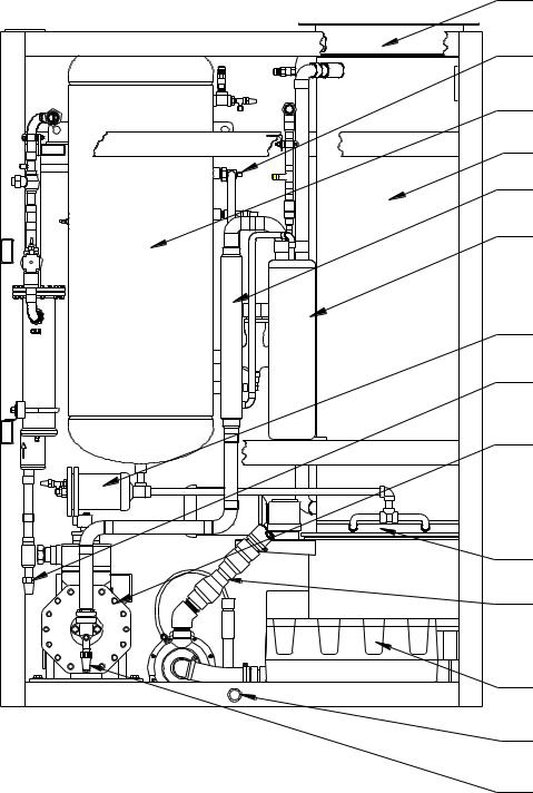
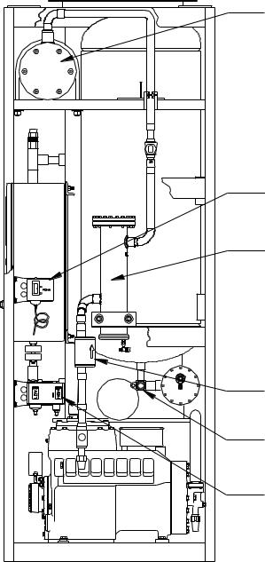
(51)FREEZER SAFETY VALVE
(50)RECEIVER SAFETY VALVE
(59)RECEIVER ACCESS VALVE
(32)CONDENSER SERVICE
(101) CHECK VALVE
VALVE
(22) FLOAT SWITCH
(55)DISCHARGE LINE STOP VALVE
(30)RECEIVER GAGE GLASS
(18)THAW GAS SOLENOID VALVE (VALVE "D")
(31)RECEIVER GAGE GLASS STOP VALVE
(22A) FLOAT SWITCH STOP VALVE
(17)HAND EXPANSION VALVE
(44)RECEIVER DRAIN VALVE
(1PG) LOW PRESSURE GAGE
(2PG) HIGH PRESSURE GAGE
(5M) CUTTER MOTOR
(5R) CUTTER GEAR REDUCER
(20)LIQUID LINE SOLENOID VALVE "A"
(94)OIL PRESSURE SWITCH
(28)CHARGING VALVE 1/4" FLARE
(43)STRAINER
1/2" MPT MAKE UP WATER CONNECTION
(6)CIRCULATING WATER PUMP
ICE DISCHARGE
(12)MAKE-UP WATER FLOAT VALVE
` |
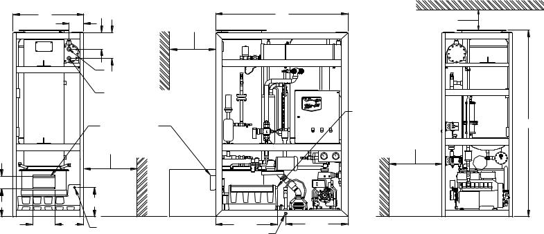
FIGURE 1-1 |
|
Assembly (Air-Cooled) |
|
Front View |
7/19/13
05TA Service Manual |
1-5 |
|
INTRODUCTION
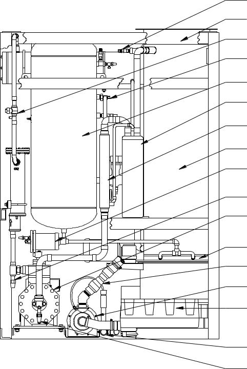
(8) WATER DISTRIBUTING CHAMBER
(91) LIQUID RETURN
STOP VALVE
(15R) RECEIVER
(2) FREEZER
(13) HEAT EXCHANGER
(88) SUCTION ACCUMULATOR
(46) LIQUID LINE FILTER DRIER
(35) COMPRESSOR DISCHARGE SERVICE VALVE
(3) COMPRESSOR
(16) THAWING CHAMBER
(6A) WATER PUMP CHECK VALVE
(7) WATER TANK
(25) WATER TANK DRAIN CONNECTION 1" FPT
(34) COMPRESSOR SUCTION SERVICE VALVE
FIGURE 1-2
Assembly (Air-Cooled)
Rear View
7/19/13
1-6 |
05TA Service Manual |
|
|
INTRODUCTION |
|
|
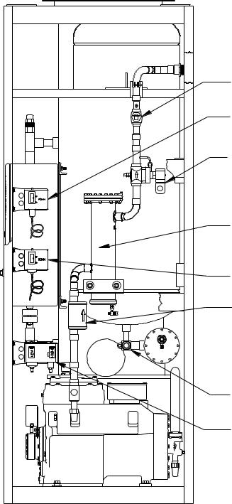
(55) DISCHARGE LINE |
|
STOP VALVE |
|
(18S) DEFROST PRESSURE |
|
SWITCH |
|
(53) COLD WEATHER |
|
SOLENOID VALVE |
|
("X" VALVE) |
|
(14) OIL SEPARATOR |
|
(41A) CONDENSER PRESSURE |
|
CONTROL SWITCH |
|
(48) COMPRESSOR |
|
DISCHARGE MUFFLER |
|
(58) LIQUID OUTLET STOP |
|
VALVE ("KING" VALVE) |
|
(4PS) DUAL HIGH/LOW |
|
PRESSURE SWITCH |
FIGURE 1-3
Assembly (Air-Cooled)
Right
Side View
7/19/13
05TA Service Manual |
1-7 |
|
|
|
INTRODUCTION |
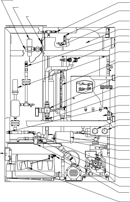
(23) CONDENSER WATER INLET
(52) CONDENSER SAFETY VALVE
(41) CONDENSER WATER
REGULATOR (50) RECEIVER SAFETY VALVE
5/8" FLARE
(24) CONDENSER WATER
OUTLET |
(59)RECEIVER ACCESS VALVE 1/4" FLARE
(15) CONDENSER
(22A) FLOAT SWITCH STOP VALVE
(90)THAWING GAS STOP VALVE
(22)FLOAT SWITCH
(30)RECEIVER GAGE GLASS
(18)THAW GAS SOLENOID VALVE "D"
(31)RECEIVER GAGE GLASS STOP VALVE
(17)HAND EXPANSION VALVE
(22A) FLOAT SWITCH STOP VALVE
(1) CONTROL PANEL
(1PG) LOW PRESSURE GAGE
(2PG) HIGH PRESSURE GAGE
(44) RECEIVER DRAIN VALVE
(5M) CUTTER MOTOR
(5R) CUTTER GEAR REDUCER
(94)OIL PRESSURE SWITCH
(28)CHARGING VALVE 1/4" FLARE
(20)LIQUID LINE SOLENOID VALVE "A"
(43) STRAINER
1/2" MPT MAKE UP WATER CONNECTION
(12) MAKE-UP WATER
FLOAT VALVE
FIGURE 1-4
Assembly (Water Cooled)
Front View
7/19/13
1-8 |
INTRODUCTION |
05TA Service Manual
(51)FREEZER SAFETY VALVE
(8)WATER DISTRIBUTOR CHAMBER
(55)DISCHARGE LINE STOP VALVE
(91)LIQUID RETURN STOP VALVE
(15R) RECEIVER
(88)SUCTION ACCUMULATOR/ HEAT EXCHANGER
(13)HEAT EXCHANGER
(2) FREEZER
(46)LIQUID LINE FILTER DRIER
(35)COMPRESSOR DISCHARGE SERVICE VALVE
(3) COMPRESSOR
(16) THAWING CHAMBER
(6A) WATER PUMP CHECK VALVE
(6)CIRCULATING WATER PUMP
(7)WATER TANK
(25)WATER TANK DRAIN CONNECTION 1" FPT
(34) COMPRESSOR SUCTION SERVICE VALVE
FIGURE 1-5
Assembly (Water Cooled)
Rear View
7/19/13
05TA Service Manual |
1-9 |
|
INTRODUCTION
(15) CONDENSER
(18S) DEFROST PRESSURE SWITCH
(14) OIL SEPARATOR
(48) COMPRESSOR DISCHARGE MUFFLER
(58) LIQUID OUTLET STOP VALVE ("KING" VALVE)
(4PS) DUAL HIGH/LOW PRESSURE SWITCH
FIGURE 1-6
Assembly (Water Cooled)
Right Side View
7/19/13
1-10 |
05TA Service Manual |
|
INTRODUCTION
7/19/13
05TA Service Manual |
2-1 |
|
RECEIPT OF YOUR TUBE-ICE MACHINE
2. Receipt Of Your Tube-Ice Machine
!WARNING !
Only service personnel experienced in refrigeration and qualified to work with high voltage electrical equipment should be allowed to install or work on this Tube-Ice® machine.
!WARNING !
Inspection As soon as you receive your machine, inspect it for any damage. If damage is suspected, note it on the shipper’s papers (i.e., the trucker’s Bill of Lading). Immediately make a separate written request for inspection by the freight line’s agent. Any repair work or alteration to the machine without the permission of the Vogt Ice®, LLC can void the machine’s warranty.
The machine was shipped with a full charge of refrigerant stored in the receiver. Visually check all lines for mechanical damage. If a leak is suspected, check all joints with a Halogen Leak Detector. All leaks should be reported to the Vogt Ice® LLC to obtain authorization for repair.
!CAUTION !
The approximate weight of the machine is 2450 pounds. Always use equipment with adequate load carrying capacity.
!CAUTION !
The machine frame has lifting lugs at each corner in the top for eyebolts and hooks to be used for lifting purposes if desired. Lifting lugs should be used whenever possible.
!CAUTION !
The Tube-Ice® machine is top heavy.
Secure to avoid tipping.
!CAUTION !
If a forklift is used, make sure its capacity is sufficient. The forks must be wide enough apart to prevent tipping sideways and must extend beyond the extremities of the frame base structure. The machine needs to be bound in place to prevent tipping.
Safety Valves Safety pressure relief valves are an integral part of the packaged Tube-Ice® machine. One is located in the low-side of the system on the freezer, and one is in the high side of the system on the receiver and one is on the condenser. Vent each of the pressure relief valves to the atmosphere in such a manner as to comply with local and national codes.
Machine Room The machine must be located inside a suitable building and must not be subjected to ambient temperatures below 50°F (10°C) or above 110°F (43.3°C). Heat from other sources (sunlight, furnaces, condenser, etc.) and unusual air current may affect the operation of the machine and should be avoided. The electrical components of the Tube-Ice® machine are rated NEMA 1. Therefore, the machine should not be located in a hazardous area or sprayed with water. The machine should be installed on a drainable condensate drip pan or in an area where water will not stand but will readily drain away from the machine. See Space Diagram for clearances and utility connections, FIGURES 3-2A and 3-2B.
7/19/13
2-2 |
05TA Service Manual |
|
|
RECEIPT OF YOUR TUBE-ICE MACHINE |
|
Storage (prior to installation or start-up). The machine must not be stored or installed in an area that may reach temperatures 115°F (46.1°C) or above.
!CAUTION !
This equipment contains HCFC-22 or HFC-404a refrigerant under pressure. Do not store in an area exposed to temperatures above 115°F (46°C)
or in direct sun at temperatures above 105°F (40°C).
!CAUTION !
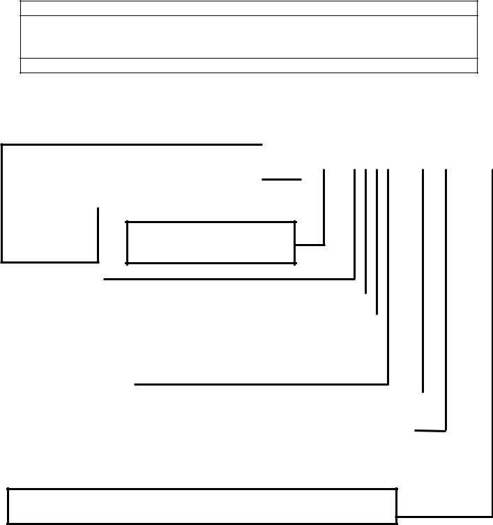
The machine nameplate is located on the front of the control panel. The model number and machine description are located in the top left hand corner. The following figure can be used to verify that the correct model has been received.
Nominal Capacity
"02K" - 2000 lbs/day "03K" - 3000 lbs/day "04K" - 4000lbs/day "03T" - 3 tons/day "05T" - 5 tons/day "10T" - 10 tons/day "25T" - 25 tons/day "50T" - 50 tons/day "80T" - 80 tons/day
|
|
|
|
("K" = 1000's lbs/day, "T" = tons/day) |
|
XXXX – XXXX – XXXX – XXX |
|
|
|
|
|
(Consult Specifications for Actual Capacity) |
|
|
|
|
|
|
|
|
|
|
|
Model Variation
A number assigned to indicate major variations within any one family series.
Basic Configuration |
|
|
|
|
|
|
|
|
|
|
|
|
|
"P" - Package |
|
|
Refrigerant |
|
|
|
|
|
|
|
|
|
|
|
|
|
|
|
|
|
|
|
|
||||
"L" - Low-side |
|
|
|
|
|
|
|
|
|
|
|
||
|
|
"F" - R-22 |
|
|
Type of Ice |
|
|
|
|
||||
"H" - High-side |
|
|
|
|
|
|
|
|
|||||
|
|
"A" - Ammonia |
|
|
"B" - Cylinder |
|
|
|
|
||||
|
|
|
|
|
|
|
|
|
|||||
|
|
|
"H" - R-404a |
|
|
|
|
|
|
||||
|
|
|
|
|
"K" - Crushed |
|
|
|
|
||||
|
|
|
|
|
|
|
|
|
|
|
|||
|
|
|
|
|
|
|
"D" - Dual Ice (Cru & Cyl) |
|
|
|
|
||
Tube Size (in 1/4's of an inch) |
|
|
|
|
|
"L" - 1 1/2" Long Cylinder |
|
|
|
|
|||
|
|
|
|
|
"X"- 2” Long Cylinder |
|
|
|
|
||||
"4" - 1" |
|
|
|
|
|
|
|
|
|
|
|||
|
|
|
|
|
|
|
|
|
|
|
|
|
|
"5" - 1 1/4" |
|
|
|
|
|
|
|
|
|
|
|
|
|
|
|
|
|
|
|
|
|
|
|
|
|
|
|
"6" - 1 1/2" |
|
|
|
|
|
|
|
|
|
|
|
|
|
"8" - 2" |
|
|
|
Electrical Codes |
|
|
Condenser Type |
|
|||||
|
|
|
|
"26" - 208/230-3-60 |
|
|
|
||||||
|
|
|
|
|
|
|
|||||||
|
|
|
|
|
|
|
|
|
|
|
|||
|
|
|
|
"46" - 460-3-60 |
|
|
|
"AC" - Air Cooled |
|
||||
|
|
|
|
|
|
|
|
|
|
|
|
||
|
|
|
|
"56" - 575-3-60 |
|
|
|
"WC" - Water Cooled |
|
||||
|
|
|
|
|
|
|
|
|
|
|
|
||
|
|
|
|
"25" - 200-3-50 |
|
|
|
"HP" - High Pressure Water Cooled |
|
||||
|
|
|
|
|
|
|
|
|
|
|
|
||
|
|
|
|
"45" - 400-3-50 |
|
|
|
"SW" - Sea Water |
|
||||
|
|
|
|
|
|
|
|
|
|
|
|
||
|
|
|
|
"21" - 230-1-60 |
|
|
|
"NC" - No Condenser |
|
||||
|
|
|
|
|
|
|
|
|
|
|
|
||
|
|
|
|
|
|
|
|
|
|
|
|
|
|
|
|
|
|
|
|
|
|
|
|
|
|
|
|
Product Variation Codes (An alphanumeric designator assigned to specific variations.) "000 or Blank" – Standard Product
If unsure of the product code shown on your machine please consult the factory.
Figure 2-1
Vogt Model Nomenclature
7/19/13

05TA Service Manual |
3-1 |
|
INSTALLING YOUR TUBE-ICE® MACHINE
3. Installing Your Tube-Ice® Machine
!WARNING !
Only service personnel experienced and certified in refrigeration and qualified to work with high voltage electrical equipment should be allowed to install or work
on this Tube-Ice® machine.
!WARNING !
Important Notice.
To activate the machine warranty, the Product Registration Form MUST be completed and returned to the factory promptly after the official start-up. Product Registration Form is located in the Owners Packet or can be found online at www.vogtice.com/registration.htm.
Piping and Drain Connections
Figure 3-2A (Air Cooled) and 3-2B (Water Cooled) show locations and sizes for all connections.
!CAUTION !
External shut-off valves must be provided in the water inlet lines.
The minimum inlet water pressure for satisfactory operation of the machine is 30 psig. The maximum allowable pressure is 100 psig.
!CAUTION !
Make-up |
Water Tank |
Condenser |
Condenser |
Water In |
Drain* |
Water In |
Water Out* |
1/2” MPT |
1” FPT |
1 1/4” FPT |
1 1/4” FPT |
TABLE 3-1
Water Supply and Drain Sizes
The condenser water outlet and water tank drain connections must be extended separately to an open drain or sump, arranged for visible discharge. Do not trap the water tank drain line, as this will interfere with the operation of the automatic blowdown system.
!CAUTION !
These lines must NOT be connected into a pressure tight common header
due to the possibility that warm condenser water may back up into the water tank. The condenser water outlet MUST be piped separately to the drain.
!CAUTION !
Note: Due to variations in water quality by geographic location, water filtering or treatment may be required to reduce maintenance and inhibit hardness buildup on machine components (tubes, valves). Consult your local water treatment company for recommendations and equipment.
3/11/14
3-2 |
05TA Service Manual |
|
INSTALLING YOUR TUBE-ICE® MACHINE
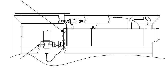
Water-Cooled Connections
Connect water supply to the water regulator valve on condenser water inlet connection (bottom connection on condenser). Connect the condenser water out line to the top connection on the condenser.
(24)1 1/4” FPT
Condenser
Water Outlet
(23) 1 1/4” FPT
Condenser Water
Inlet
FIGURE 3-1
Water Cooled Condenser Connections
Cooling Tower.
For water cooled machines only. When selecting a cooling tower, careful attention must be given to operating wet bulb conditions. It is advisable to check with your local cooling tower distributor for their recommendations based on actual operating conditions in your area. An average wet-bulb of 78°F is typical in the U.S. but many localities have design wet-bulbs as low as 72°F or as high as 82°F.
The cooling tower water pump must be capable of delivering the required volume of water through the condenser. Due to cooling tower location and pressure drop through water lines and water regulating valves, the pump must be sized for each installation. Refer to TABLE 11-1 for condenser water requirements. The water piping for the cooling tower and the installation of the pump must be in accordance with the manufacturer’s instructions.
Proper water treatment for the prevention of mineral and foreign matter accumulation in the condenser or cooling tower is recommended. A water analysis should be obtained to determine the proper chemicals to use.
7/19/13
7/19/13
FIELD ATTACHMENT
AIR COOLED CONDENSER TUBING
Manual Service 05TA
|
|
|
|
ROTA-LOCK FIELD CONNECTOR |
|
ROTA-LOCK FIELD CONNECTOR |
|
|
|
|
|
PART#12A-2396A0501 |
|
|
|
|
|
|
|
|
PART#12A-2396A0601 |
|
|
|
|
|
|
1-1/8" IDS X 1-1/4 - 12 THREADS (F) |
|
|
|
andConnections |
|
|
|
|
1-3/8" IDS X 1-3/4 - 12 THREADS (F) |
|
|
|
|
|
|
|
|
||
|
|
|
|
ROTA-LOCK TEFLON FIBER SEAL |
|
ROTA-LOCK TEFLON FIBER SEAL |
|
|
|
|
|
PART# 12A-2600T01 |
|
|
|
|
|
|
|
|
PART# 12A-2600T03 |
|
|
|
|
|
|
|
|
|
|
|
|
|
|
|
|
(SHOWN FROM TOP OF ICE MACHINE) |
|
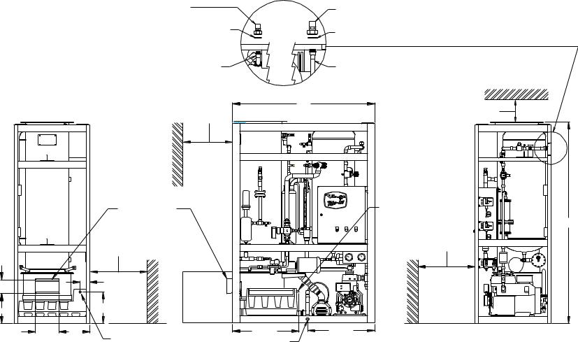
(AirDiagramSpace |
2A-3FIGURE |
|
|
LIQUID RETURN LINE |
|
DISCHARGE LINE |
|
|
|
30" MINIMUM CLEARANCE |
60" |
12" MINIMUM CLEARANCE FOR |
|
||
|
|
|
|
|
|
||
|
|
|
|
FOR CONDENSER CLEANING |
|
INSTALLATION AND ACCESS |
|
Cooled |
|
|
|
ICE DISCHARGE |
|
1/2" MPT |
|
|
|
|
|
|
|
MAKE-UP |
|
Machine) |
|
|
|
|
|
WATER IN |
85" |
|
|
|
|
|
40" MINIMUM CLEARANCE |
|
|
|
|
|
40" MINIMUM CLEARANCE |
|
FOR COMPRESSOR ACCESS |
|
|
|
|
|
FOR WATER TANK ACCESS |
|
|
|
|
|
5 7/8" |
|
4" |
|
|
|
|
|
|
|
PROVIDE |
|
|
|
|
|
|
|
|
|
|
|
|
|
|
|
|
SUFFICIENT |
|
|
|
|
12 5/8" |
|
13 3/8" |
SPACE |
|
|
|
|
10" |
13" |
1/2" MPT MAKE-UP |
27 7/8" |
28 3/8" |
|
|
|
|
|
|
|
|
||
|
|
|
|
WATER IN |
1" FPT DRAIN |
|
|
|
|
|
|
|
|
|
|
|
|
|
|
|
(REAR OF UNIT) |
|
|
|
LEFT SIDE VIEW |
|
|
FRONT VIEW |
RIGHT SIDE VIEW |
|
|
ICE-TUBE YOUR INSTALLING |
|
® |
|
MACHINE |
3 |
|
3- |
7/19/13
and Connections |
32" |
|
7 1/2" |
30" MINIMUM CLEARANCE |
60" |
|
Diagram Space |
|
|||||
|
|
|
|
|||
6 5/8" |
|
|
FOR CONDENSER CLEANING |
|
||
3 FIGURE |
|
11 3/4" |
|
|
|
|
|
1 1/4" FPT |
|
|
|||
|
CONDENSER |
|
|
|||
|
WATER OUT |
|
|
|||
(Water |
2B- |
|
1 1/4" FPT |
|
|
|
|
CONDENSER |
|
|
|||
|
WATER IN |
|
|
|||
|
ICE DISCHARGE |
|
|
|||
Cooled |
|
|
|
|
||
|
|
40" MINIMUM CLEARANCE |
|
|
||
|
|
FOR WATER TANK ACCESS |
|
|
||
|
|
|
|
|
|
|
Machine) |
5 7/8" |
|
|
|
PROVIDE |
|
|
|
|
|
|
||
|
|
|
|
SUFFICIENT |
|
|
12 5/8" |
|
13 3/8" |
|
SPACE |
|
|
|
|
|
|
|
|
|
|
10" |
13" |
1/2" MPT MAKE-UP |
27 7/8" |
28 3/8" |
|
|
|
|
|
|
||
|
|
|
WATER IN |
1" FPT DRAIN |
|
|
|
|
|
|
|
(REAR OF UNIT) |
|
LEFT SIDE VIEW |
FRONT VIEW |
|
|
|
-3 |
|
L |
INSTALLING |
4 |
|
EARANCE |
|
|
|
|
ICE-TUBE YOUR |
|
|
|
® |
|
12" MINIMUM CLEARANCE FOR |
MACHINE |
|
|
|
|
||
INSTALLATION AND ACCESS |
|
|
|
1/2" MPT |
|
|
|
MAKE-UP |
|
85" |
|
WATER IN |
|
|
|
|
|
|
|
40" MINIMUM C |
|
|
|
FOR COMPRESSOR ACCESS |
|
|
|
RIGHT SIDE VIEW 05TAService
Manual
05TA Service Manual |
3-5 |
|
INSTALLING YOUR TUBE-ICE® MACHINE
Wiring and Electrical Connection
!WARNING !
Only service personnel experienced in refrigeration and qualified to work with high voltage electrical equipment should be allowed to install or work on the Tube-Ice® machine.
!WARNING !
Refer to TABLE 3-2 below to properly size wiring connections. A fused disconnect must be provided near the Tube-Ice® machine. Connect 3 phase power to the power distribution block (PDB) for operation of the Tube-Ice® machine and its controls. Rotation checking of cutter motor and water pump is required (see following section). Also, if one leg of the 3 phase power is higher or lower (“Wild”), then it should be connected to terminal #L2. Connect the “Ground” wire to the “Ground” lug provided.
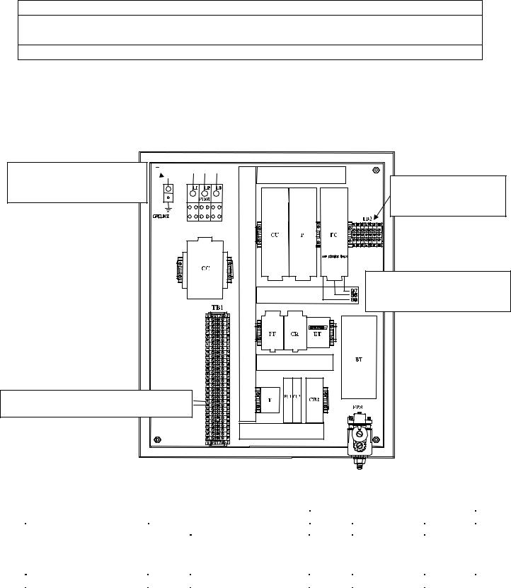
MAIN MACHINE POWER  Incoming power to be connected to
Power Distribution Block (PDB)
AUX CONNECTIONS
Cutter Motor, Pump Motor
& Compressor Interlocks
AIR COOLED CONDENSER
CONNTECTIONS
Power for Fan Motors (B7, B8 & B9)
AIR COOLED CONDENSER CONNTECTIONS
Power for Condenser control circuit (11 & 22)
FIGURE 3-3
Control Panel Power Connections
Standard Voltages |
|
Water Cooled |
|
|
Air Cooled |
|
|
|
|
|
|
|
|
||
F.L.A. |
Min. Ampacity |
Max. Fuse |
F.L.A. |
Min. Ampacity |
Max. Fuse |
||
|
|||||||
208/230, 3ph, 60 Hz |
66.9 |
81.8 |
145 |
80.9 |
95.8 |
160 |
|
460, 3ph, 60 Hz |
32.7 |
39.9 |
70 |
39.7 |
46.9 |
80 |
|
220, 3ph, 50 Hz |
67.5 |
82.4 |
145 |
81.5 |
95.8 |
160 |
|
400, 3ph, 50 Hz |
33.2 |
40.4 |
70 |
40.2 |
47.4 |
80 |
TABLE 3-2
Electrical Specifications
7/19/13

3-6 |
05TA Service Manual |
|
INSTALLING YOUR TUBE-ICE® MACHINE
Phase Check
!CAUTION !
DO NOT attempt to start machine without priming pump and insuring proper rotation of both cutter and pump.
Refer to FIGURE 3-2A & 3-2B (space diagram) for connection locations.
!CAUTION !
Cutter and pump motor rotation are factory synchronized but must be checked at installation. For ice production, the cutter disc, as viewed at the ice discharge opening should turn from left to right (crushed rotation should be from right to left). The pump rotation should match the marking on the pump housing. The pump will need to be primed by starting the machine in the clean mode and allowing it to run for several minutes. To change direction of rotation for both, cutter and pump, disconnect power and reverse L1 and L3 (incoming power wires) at the compressor motor contactor.
Voltage Unbalance Voltage unbalance can cause motors to overheat and fail.
The maximum voltage unbalance between any two legs should be no greater than 2%.
Example: Supply Voltage = 230-3-60
Voltage Readings: |
AB = 220 Volts |
|
|
BC = 225 Volts |
Average = (220 + 225 + 227)/3 = 224 Volts |
|
AC = 227 Volts |
|
(AB) 224-220 |
= 4 |
Volts (Highest Deviation) |
|
(BC) 225-224 |
= 1 |
Volts |
% Voltage Unbalance = 100 x (4/224) = 1.78% “Acceptable” |
(AC) 227-224 = 3 Volts |
|
||
Important: If the supply voltage phase unbalance is more the 2%, contact your local electric utility company.
Current Unbalance Voltage unbalance will cause a current unbalance, but a current unbalance does not necessarily mean that a voltage unbalance exists. A loose terminal connection or a buildup of dirt or carbon on one set of contacts would cause a higher resistance on that leg than on the other two legs. Current follows the path of least resistance, therefore if terminal connection L1 is loose or dirty, L2 and/or L3 will have higher current. Higher current causes more heat to be generated in the motor windings.
The maximum acceptable current unbalance is 10%.
Example:
Current Readings: |
L1 = 96 Amps |
|
||
|
|
|
L2 = 91 Amps |
Average = (96 + 91 + 98)/3 = 95Amps |
|
|
|
L3 = 98 Amps |
|
(L1) 96-95 |
= 1 |
Amps |
|
|
(L2) 95-91 |
= 4 |
Amps (Highest Deviation) |
% Current Unbalance = 100 x (4/95) = 4.2% “Acceptable” |
|
(L3) 98-95 |
= 3 |
Amps |
|
|
7/19/13
05TA Service Manual |
3-7 |
|
INSTALLING YOUR TUBE-ICE® MACHINE
Air-Cooled Condenser Installation Instructions
!WARNING !
These installation guidelines must be followed to obtain reliable operation from air cooled ice machines.
IF THESE GUIDELINES ARE NOT FOLLOWED THE COMPRESSOR WARRANTY WILL NOT BE HONORED.
!WARNING !
1.Use only Vogt approved condensers. Any exceptions to this policy must be obtained in writing from Vogt prior to installation and operation of the ice machine.
2.Outdoor condensers must be installed with vertical air flow. Indoor condensers used for heat recovery may be installed with either horizontal or vertical air flow.
NOTE: Condenser must be ordered for horizontal air flow.
3.The condenser must be mounted above the ice machine.
4.Horizontal runs in the liquid return line should slope 1/4” per foot with liquid refrigerant draining freely in the direction of normal operating flow (back to the ice machine) with no traps in the liquid line.
5.Horizontal runs in the discharge line should slope 1/4” per foot in the normal direction of flow (away from the ice machine).
6.Traps must be installed in discharge lines at the base of all vertical risers. There should be no intentional traps in liquid lines. Trap volume should be kept to a minimum. Long vertical rises should have traps every 20 feet. Typical details are shown in FIGURE 3-6.
7.Flooding head pressure controls such as Alco Headmaster are not to be used since they cause excessive subcooling of the returned liquid refrigerant and interfere with reliable ice harvest.
8.The discharge and liquid lines must be insulated with 1/2” thick Armaflex insulation or equal.
9.Use only ACR grade copper pipe, Type L. Recommended line sizes are shown in TABLE 3-5.
10.For field attachment instructions, see FIGURE 3-5.
11.Distance between ice machine and condenser must not exceed 150 equivalent feet. Refer to Condenser Equivalent Line Size worksheet (see TABLE 3-5 ).
12.Condensers must be provided with a cold weather valve kit per FIGURE 3-5. These valves allow one-half of the condenser to be disabled in cold weather. Running the ice machine with one-half of the condenser in cold weather makes it easier to maintain minimum necessary condensing pressure particularly in windy conditions.
13.Condensers with multiple fans must be provided with a thermostat to turn off unneeded fans in cold weather. Turning off unneeded fans reduces on-off cycling of the fan(s) and allows for a steadier condensing pressure and more consistent warm gas for ice harvesting FIGURE 3-7.
3/14/14

3-8 |
05TA Service Manual |
|
INSTALLING YOUR TUBE-ICE® MACHINE
14.When extreme cold conditions are expected or encountered (temperatures below 0°F and wind greater than 15 MPH), it may be necessary to install a protective enclosure around the condenser. Apparatuses such as louvers may also be used for varying conditions. Contact the factory for suggestions.
15.After installation, the field installed lines are to be evacuated to a vacuum of 500 microns or less and held for at least one hour. After the vacuum pump is removed, vacuum should hold at 500 microns or less for at least 5 minutes.
16.The machine is shipped with a full operating charge of refrigerant sufficient to fill the condenser and connecting lines. If the condenser piping is longer than 50 feet (one way), additional R-22 or R-404a may need to be added to retain enough refrigerant in the receiver for thawing purposes (see table. Refer to the operating level mark on the receiver and charge accordingly. Each 1” of liquid level in the receiver equals approximately 5.5 pounds of R-22 or R-404a.
Liquid Line Size |
75 ft. |
100 ft. |
125 ft. |
150 ft. |
1/2” |
none |
None |
None |
2 |
5/8” |
none |
2 |
4 |
6 |
7/8” |
none |
4 |
8 |
12 |
1-1/8” |
none |
6 |
12 |
18 |
|
|
TABLE 3-3 |
|
|
Pounds of R-22/404A to Add vs. Liquid Line Length |
|
|||
17.All piping must be done in accordance with applicable local and national codes. Such codes may include “The Safety Code For Mechanical Refrigeration” (ANSI B9.1) and “The Code For Refrigerant Piping” (ANSI B31.5).
18.The following installation guidelines are strongly suggested. While they do not affect the machine warranty, they may be required for safe operation and to comply with all applicable electrical and mechanical codes:
a.Local electrical code must be checked for wiring method.
b.The installer must provide a disconnect switch(s) adjacent to the condenser.
c.Electrical connections between the condenser and the Tube-Ice® machine require minimum 12 ga. wire.
d.All electrical fittings and components exposed to the weather must be suitable for outdoor installation.
The design total heat rejection for each Tube-Ice® machine, the recommended air-cooled condenser, and condenser physical and electrical data are shown on the next page. Specified energy efficiency ratings of the ice machines are based on use of the recommended condenser and approved piping practices.
Recommended condensers provide the indicated total heat rejection at 90°F ambient, 100°F condensing. Vogt Ice, LLC is not responsible for head pressure problems if other than the recommended condensers are used. For continuous operation at ambient temperature above 105°F, consult the factory about using a larger condenser.
7/19/13
 Loading...