

Page 1

03TA
®
TUBE-ICE
MACHINE
(Includes models HE60 & P112F)
Service Manual
$50
00
Page 2

NOTICE
This manual is the property of the owner of this particular Tube-Ice®
machine.
Model #____________________ Serial #____________________.
It is to be left on the premises with this machine at all times. After startup, it should be stored in a safe place where it can be readily available
when needed for future reference in maintaining troubleshooting or
servicing.
Failure to comply with this notice will result in unnecessary
inconvenience and possible additional expenses.
This manual is intended as an informational tool for the installation,
operation, maintenance, troubleshooting, and servicing of this
equipment. If an existing situation calls for additional information not
found herein, we suggest that you contact your distributor first. If further
assistance or information is needed, please feel free to contact the factory
at 502-635-3000 or FAX at 502-635-3024.
IMPORTANT: The Warranty Registration/Start-Up Report found in the
front of this manual is to be completed and returned to the factory
promptly after the official start-up.
Please return to: TUBE ICE, LLC
1000 W. Ormsby Ave.
Louisville, KY 40210
Page 3
Tube Ice L.L.C.
Vogt Order Number: ____________________
1000 W. Ormsby
Louisville, KY 40210
(502) 635-3235
FAX #502-635-3024
THIS FORM MUST BE SENT TO
VOGT TO ACTIVATE WARRANTY
Warranty Registration / Start-Up Form
(Medium & Large Machines)
Model Number: __________________________ Serial Number: __________________________
This form must be filled out completely and signed by the customer in order to assure acceptance by Vogt.
Date of Start-Up: _______________________________ Form Completed By: _____________________________________
AC Condenser Model Number: _____________________ AC Condenser Serial Number: _____________________________
Water Treatment System? Yes No Manufacturer: ____________________ Model: ________________________
Bin Manufacturer: _______________________ Model: _________________________ Bin Capacity: _______ lbs.
Distributor
Company Name: ____________________________________________ Phone: _______________________
Address: ____________________________________ City: _________________________ State: ___________ Zip: ___________
Service Company
Company Name: ____________________________________________ Phone: _______________________
Address: ____________________________________ City: _________________________ State: ___________ Zip: ___________
Customer (location of equipment)
Company Name: ____________________________________________ Phone: _______________________
Address: ____________________________________ City: _________________________ State: ___________ Zip: ___________
PRE-OPERATION CHECK
Machine room suitable 50°F minimum, 110°F maximum
Power Supply ______ V _____ PH _____ HZ (machine not running)
Crankcase heater on for 2 hours minimum, prior to start
All valves opened or closed as tagged
Water supply and drains connected properly
Sufficient make-up water supply (minimum 30 PSIG)
Leak checked entire system (including AC condenser if applicable)
AC condenser cold weather temperature setting(s)
Solenoid ________ Fan________
AC condenser installed above machine Yes No
Approx. _____ft.
AC condenser line length (in equivalent feet) ____________
AC condenser properly piped — all lines insulated
Bin control(s) installed properly
Instruction manual and warranty certificate left on-site
Name of person left with: __________________________________
Test
Cycle
#1
#2
#3
#4
Make-up Water
Temp
Note: Ice lb. per day can be found by:
Freeze Time
Min/Sec
Harvest Time
Min/Sec
harvestper lb. ice
+ me)harvest ti time(freeze
First Ice Out
Min/Sec
1440×
Power Supply ______ V _____ PH _____ HZ (machine running)
Compressor oil level, i.e. 1/4 – 1/2 – 3/4: ______
Compressor, pump , cutter & other motor direction of rotation correct
Compressor amps (Start of freeze cycle) L1_____ L2_____ L3_____
Cutter motor amps RLA__________ Actual __________
Water pump amps RLA__________ Actual __________
Condenser motor amps (if applicable) _________
Incoming potable water temperature: _____°F
All water distributors in place (visually inspected)
Make-up water float valve adjusted properly
Clear ice Yes No
Bin control(s) operate(s) properly to stop and start machine with ice
on them
Hour meter in control panel connected and operating
Suction Pressure: End of freeze ________ End of harvest ________
Discharge Pressure: End of freeze ________ End of harvest ________
All Ice Out
Min/Sec
OPERATION CHECK
Avg. Hole
Size
Ice
Lb. Per Harvest
Lb. Per Day
Remarks:
Ice
Technician Signature: ___________________________ End User Signature:_____________________________
I certify that I have performed all of the above procedures.
Page 4

03TA Service Manual
Page No.
1. INTRODUCTION
A Brief History of Our Company............................................................................................................................1-1
Vogt Energy-Savings Tube-Ice® Machines.............................................................................................................1-1
Preview .............................................................................................................................................................1-1
Important Safety Notice..........................................................................................................................................1-2
Special Precautions To Be Observed When Charging Refrigeration Systems ..........................................................1-2
Safety Symbols and What They Mean ....................................................................................................................1-3
Assembly Drawing Model 03TA Air-Cooled, FIGURES 1-1, 1-2, & 1-3................................................................. 1-4, 1-5, 1-6
Assembly Drawing Model 03TA Water-Cooled, FIGURES 1-4, 1-5, & 1-6 ............................................................1-7, 1-8, 1-9
TABLE OF CONTENTS
Vogt
i
TABLE OF CONTENTS
®
TUBE-ICE® MACHINES
Model 03TA
2. RECEIPT OF YOUR TUBE-ICE MACHINE
Inspection .............................................................................................................................................................2-1
Safety Valves ......................................................................................................................................................... 2-1
Machine Room.......................................................................................................................................................2-2
Storage (prior to installation and start-up).............................................................................................................. 2-2
3. INSTALLING YOUR TUBE-ICE MACHINE
Bin Installation ......................................................................................................................................................3-1
Setting the Ice Machine on the Bin......................................................................................................................... 3-1
Ice Chute Location/Machine Footprint, FIGURE 3-1 ..............................................................................................3-1
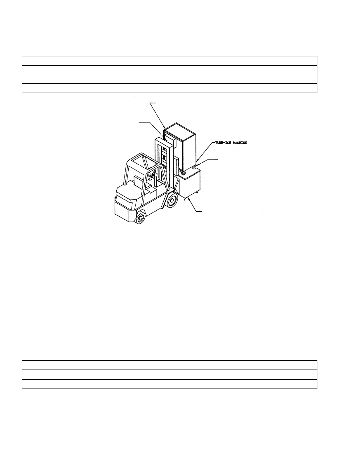
Forklift and Blocks Method, FIGURE 3-2.............................................................................................................. 3-2
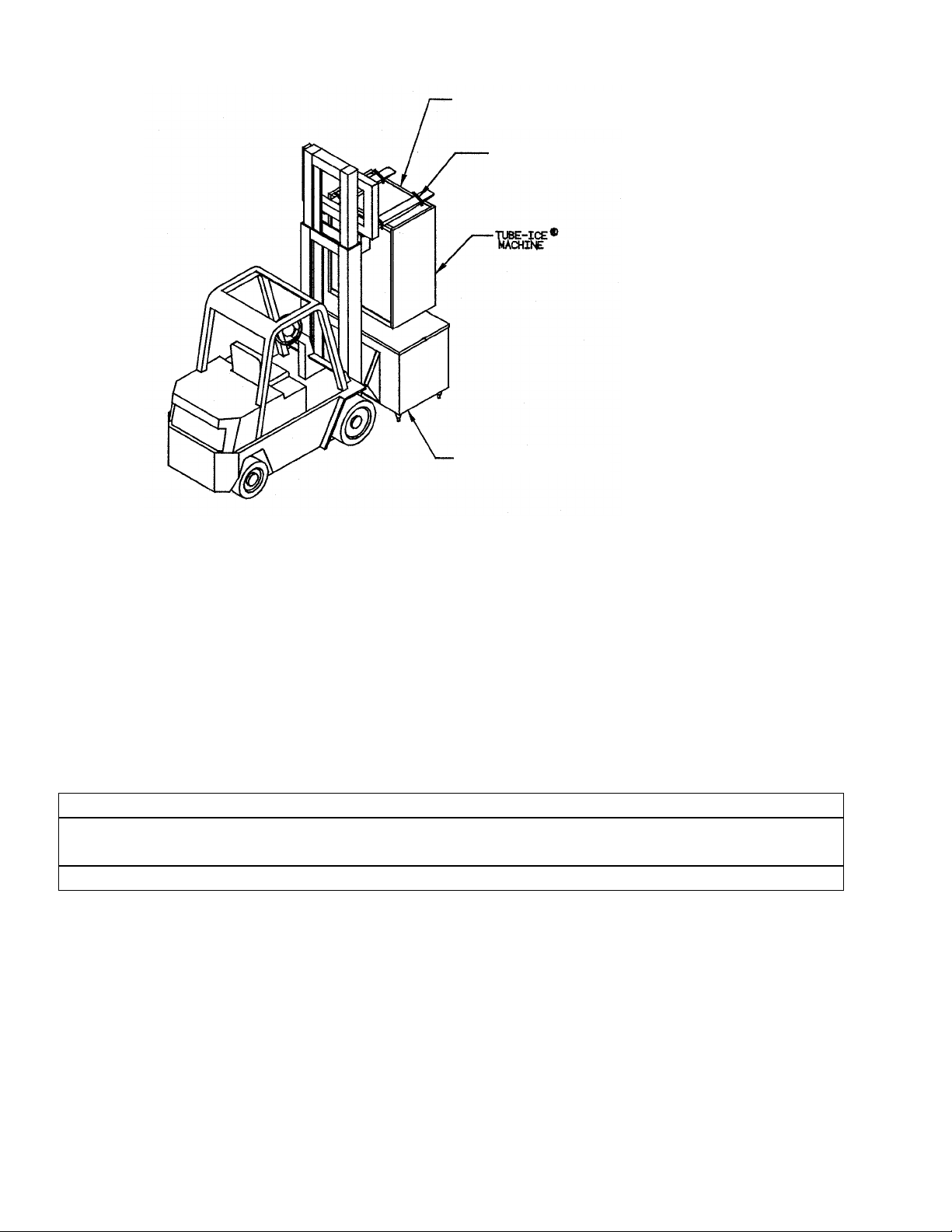
Forklift and Ropes or Lifting Strap Method, FIGURE 3-3.......................................................................................3-3
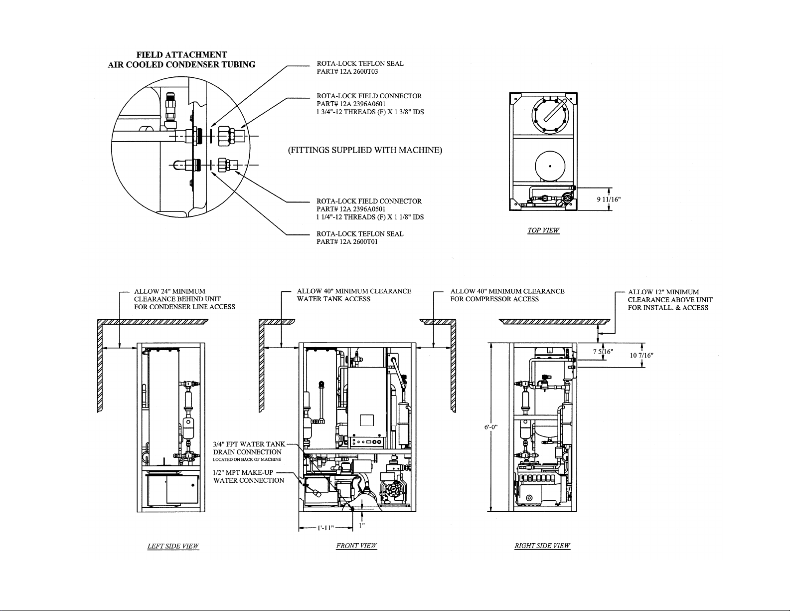
Connections and Space Diagram (Air-Cooled Machine), FIGURE 3-4....................................................................3-4
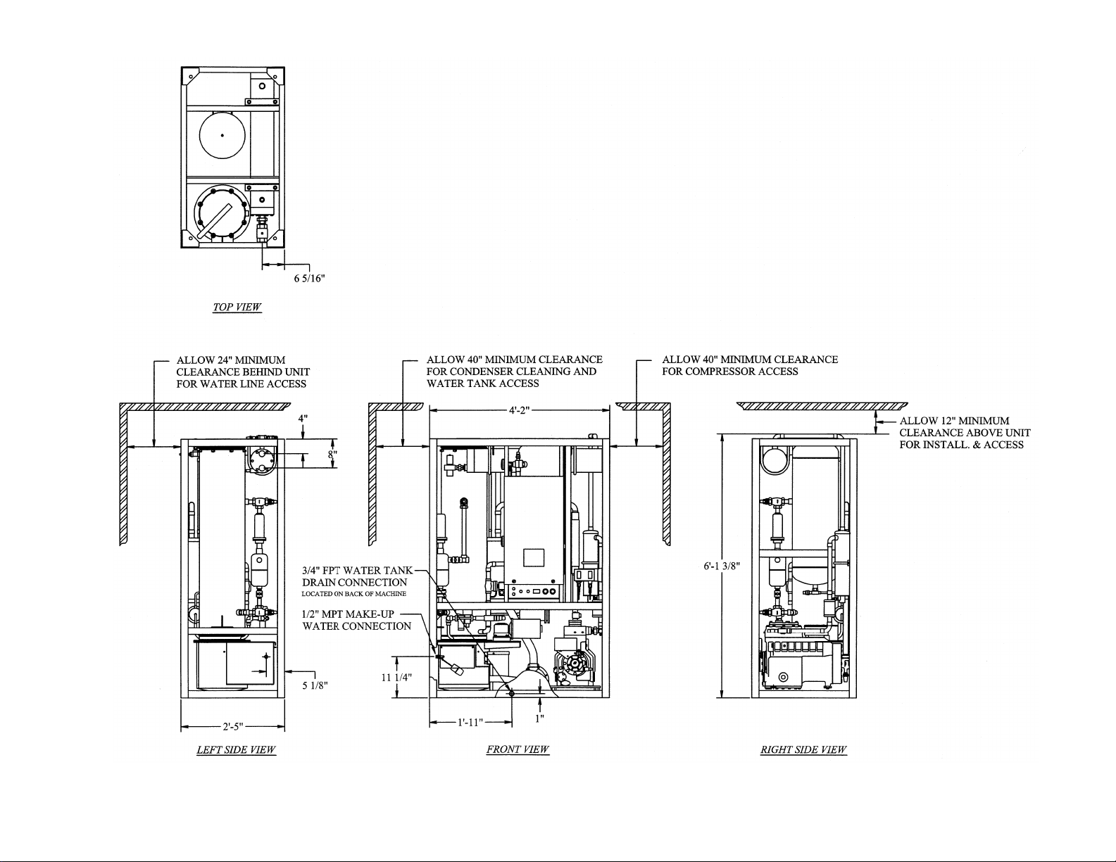
Connections and Space Diagram (Water-Cooled Machine), FIGURE 3-5................................................................ 3-5
Piping and Drain Connections................................................................................................................................3-6
Water Supply and Drain Sizes, TABLE 3-1 ............................................................................................................ 3-6
Cooling Tower.......................................................................................................................................................3-6
Wiring and Electrical Connection........................................................................................................................... 3-7
Control Panel Power Connections, FIGURE 3-6.....................................................................................................3-7
Electrical Specifications, TABLE 3-2.....................................................................................................................3-7
Phase Check ..........................................................................................................................................................3-8
Voltage Unbalance................................................................................................................................................. 3-8
Current Unbalance.................................................................................................................................................3-8
Air-Cooled Condenser Installation Instructions....................................................................................................... 3-9
Pounds of R-22 To Add Vs. Liquid Line Length, TABLE 3-3.................................................................................3-10
Air-Cooled Condenser Data ...................................................................................................................................3-11
9/28/98
Page 5

ii
TABLE OF CONTENTS
Condenser Dimensions (Condenser Pictured: DD-231), FIGURE 3-7 .....................................................................3-12
Condenser Field Piping (Cold Weather Valve Kit), FIGURE 3-8............................................................................ 3-12
Condenser Equivalent Line Size Worksheet ...........................................................................................................3-13
Equivalent Feet Due To Friction, TABLE 3-5 ........................................................................................................3-13
Minimum Traps For Discharge Lines, FIGURE 3-9................................................................................................3-13
Air-Cooled Condenser Wiring................................................................................................................................3-14
Wiring for #DD-231 & #DD-261 Condenser, FIGURE 3-10...................................................................................3-14
Air-Cooled Connections.........................................................................................................................................3-14
Rota-lock Connector Torque Ratings, TABLE 3-6.................................................................................................. 3-14
Ice Bin Thermostat Sensor Installation ...................................................................................................................3-15
Ice Bin Thermostat Location, FIGURE 3-11........................................................................................................... 3-15
Programming the Electronic Ice Bin Thermostat ..................................................................................................... 3-16
4. HOW YOUR TUBE-ICE MACHINE WORKS
Principle of Operation ............................................................................................................................................ 4-1
Freeze Period ......................................................................................................................................................... 4-2
Harvest Period....................................................................................................................................................... 4-2
Piping Nomenclature, TABLE 4-1..........................................................................................................................4-2
Water-Cooled Piping Schematic, FIGURE 4-1........................................................................................................4-3
Air-Cooled Piping Schematic, FIGURE 4-2 ............................................................................................................ 4-4
03TA Service Manual
Page No.
5. START-UP AND OPERATION
Refrigeration System Review................................................................................................................................. 5-1
Refrigerant Charge.................................................................................................................................................5-1
Start-Up Checklist .................................................................................................................................................5-2
Start-Up .............................................................................................................................................................5-3
Control Panel Switch Layout, FIGURE 5-1............................................................................................................5-3
Adding Refrigerant ................................................................................................................................................5-4
Operating Tips ....................................................................................................................................................... 5-5
6. ELECTRICAL CONTROLS & THEIR FUNCTIONS
Control Panel (Cover Removed), FIGURE 6-1 .......................................................................................................6-1
Description of Control Panel Parts, TABLE 6-1......................................................................................................6-2
Electrical Schematic All Voltages 50-60 Hz. (Across Line Start), FIGURE 6-2....................................................... 6-3
7. MAINTENANCE
Ice-Making Section................................................................................................................................................ 7-1
Cleaning Procedure ................................................................................................................................................ 7-1
Water Distributors .................................................................................................................................................7-2
Water Tank............................................................................................................................................................ 7-2
Water-Cooled Condensers, Checking Operation .....................................................................................................7-2
Water-Cooled Condensers, Draining ......................................................................................................................7-3
Water-Cooled Condenser Cleaning.........................................................................................................................7-4
Lubrication ............................................................................................................................................................7-5
Page 6

03TA Service Manual
TABLE OF CONTENTS
Page
No.
Compressor......................................................................................................................................................7-5
Cutter Gear Reducer ........................................................................................................................................7-6
Preventive Maintenance.........................................................................................................................................7-6
Daily Check List ..............................................................................................................................................7-7
Note To Manager or Owner.............................................................................................................................. 7-7
Preventive Maintenance Program .....................................................................................................................7-8
8. TROUBLESHOOTING
List Of Symptoms.................................................................................................................................................. 8-1
Machine Won’t Run...............................................................................................................................................8-2, 8-3
Freeze-Up Due To Extended Freezing Period.........................................................................................................8-4
Freeze-Up Due To Ice Failing To Discharge...........................................................................................................8-5
Low Ice Capacity ...................................................................................................................................................8-6
Low Compressor Oil Level.....................................................................................................................................8-7
Poor Ice Quality..................................................................................................................................................... 8-8
High Head Pressure (Water-Cooled) ......................................................................................................................8-9
High Head Pressure (Air-Cooled)........................................................................................................................... 8-10
iii
9/28/98
9. SERVICE OPERATIONS
Adjustable Blowdown (For Clearer Ice) .................................................................................................................9-1
Automatic Blowdown (Harvest Cycle)....................................................................................................................9-1
Float Valve (Make-Up Water)................................................................................................................................9-1
Float Switch...........................................................................................................................................................9-1
Hand Expansion Valve...........................................................................................................................................9-2
Freezer Pressure Switch.........................................................................................................................................9-2
Freezer Pressure Switch (Allen-Bradley), FIGURE 9-1 ..........................................................................................9-2
High-Low Pressure Switch.....................................................................................................................................9-3
High-Low Pressure Switch, FIGURE 9-2................................................................................................................9-3
Head Pressure ........................................................................................................................................................ 9-4
Water-Cooled Units ...............................................................................................................................................9-4
Air-Cooled Units....................................................................................................................................................9-4
Water Regulating Valve, FIGURE 9-3A.................................................................................................................9-4
Condenser Fan Switch, FIGURE 9-3B....................................................................................................................9-4
Compressor Crankcase Heater................................................................................................................................9-5
Compressor Motor Protection................................................................................................................................. 9-5
High Potential Testing......................................................................................................................................9-6
Field Troubleshooting ......................................................................................................................................9-6
Electronic Module & Compressor Terminal Board Connections, FIGURE 9-4 ..................................................9-7
Sentronic Oil Pressure Safety Control ....................................................................................................................9-8
Oil Pressure Sensor .......................................................................................................................................... 9-8
Oil Pressure Module ........................................................................................................................................9-8
Thawing Timer, FIGURE 9-5................................................................................................................................. 9-9
Page 7

iv
TABLE OF CONTENTS
Thawing Timer...................................................................................................................................................... 9-9
Control Circuit Protection ......................................................................................................................................9-9
Condenser Cleaning...............................................................................................................................................9-9
Air-Cooled Condenser............................................................................................................................................9-9
Cutter Gear Reducer ..............................................................................................................................................9-9
Pump Down...........................................................................................................................................................9-10
Removal Of Refrigerant From Machine .................................................................................................................. 9-10
Refrigerant Leaks...................................................................................................................................................9-11
Non-Condensable Gases.........................................................................................................................................9-11
Compressor Motor Burnout .................................................................................................................................... 9-11
Solenoid Valve ......................................................................................................................................................9-12
Solenoid Valve (“D” Valve), FIGURE 9-6A........................................................................................................... 9-12
Solenoid Valve (“A” Valve), FIGURE 9-6B...........................................................................................................9-12
Circulating Water Pump Motor ..............................................................................................................................9-12
Capacity Control Valve (Internal Construction)...................................................................................................... 9-13
Copeland Compressor Unloader Valve, FIGURE 9-7..............................................................................................9-13
Loaded Operation (Freeze Period)....................................................................................................................9-13
Unloaded Operation (During Thaw Only) ......................................................................................................... 9-13
Component Removal and Replacement Operations ................................................................................................. 9-14
Cutter Motor....................................................................................................................................................9-14
Cutter Gear Reducer ........................................................................................................................................9-14
Water Tank......................................................................................................................................................9-15
Cutter & Bearing..............................................................................................................................................9-15
Cutter/Tank Assembly Nomenclature, TABLE 9-1................................................................................................. 9-16
Cutter, Water Tank & Drive Gear Assembly, FIGURE 9-8.....................................................................................9-17
Water Tank & Pump Assembly, FIGURE 9-9......................................................................................................... 9-18
Crushed Ice Production ..........................................................................................................................................9-18
03TA Service Manual
Page No.
10. OPTIONS AND ACCESSORIES
PLC (Programmable Logic Controller) .................................................................................................................. 10-2
Power Monitor ...................................................................................................................................................... 10-14
11. TABLES AND CHARTS
03TA Ratings (60 Hz., 7.5 HP), TABLE 11-1 ........................................................................................................11-2
03TA Ratings (50 Hz., 10 HP), TABLE 11-2 .........................................................................................................11-3
03TA Capacity Ratings, TABLE 11-3 ....................................................................................................................11-4
03TA Condenser Water Usage, TABLE 11-4 .........................................................................................................11-5
03TA Make-up Water Usage, TABLE 11-5............................................................................................................11-5
03TA Normal Operating Vitals, TABLE 11-6 ........................................................................................................11-5
Recommended Spare Parts List..............................................................................................................................11-6
Temperature - Pressure Chart for Common Refrigerants, TABLE 11-7...................................................................11-7
Conversion Factors: English to Metric, TABLE 11-8..............................................................................................11-8
Constants, TABLE 11-9.........................................................................................................................................11-8
Page 8

03TA Service Manual
1. Introduction
TUBE ICE, LLC
A Brief History Of Our Company Henry Vogt Machine Co. was founded as a small machine shop
in Louisville, Kentucky in 1880. In 1938, Vogt built the first Tube-Ice® machine and revolutionized
the ice-making industry. Our first “sized-ice” machine quickly replaced the old can-ice plants, which
required much hard labor and large amounts of floor space for freezing, cutting, and crushing ice by
hand.
Today, TUBE ICE, LLC carries on the tradition as one of the world’s leading producers of icemaking equipment.
Vogt Energy-Saving Tube-Ice Machines Are Cost Effective Today, Vogt Tube-Ice® machines
enjoy a well-earned reputation as the most energy efficient, dependable ice-making equipment in the
world.
1-1
INTRODUCTION
Using as little as one-half to one-third the energy required by competitors’ icemakers, Tube-Ice
machines produce the same amount of ice--in restaurants, sports arenas, packing plants, and
wholesale operations around the globe--at great savings.
In addition, Tube-Ice® machines are renowned for their long life, giving many customers more than 35
years of dependable service. Ask someone who owns one.
Preview All the skill in engineering and fabrication that we have learned in over a century of
experience is reflected in the 03TA model Tube-Ice® machines. Since Vogt introduced Tube-Ice
machines in 1938, the process of making Tube-Ice® ice has been widely recognized as the most
economical means of production. The machine’s economic and reliable operations have been proven
over and over again, in a network of varied types of installations throughout the world.
Furnished with your machine is the “Certificate Of Test”--the report of operating data that is a record
of the unit’s satisfactory operation on our factory test floor. It is evidence of our desire to deliver to
you “the finest ice-making unit ever made.”
This manual is designed to assist you in the installation, start-up, and maintenance of your unit. Your
Tube-Ice® machine will give you a lifetime of service when you install it, maintain it, and service it
properly.
®
®
9/28/98
Please read your manual carefully before attempting installation, operation, or servicing of this
professionally designed piece of equipment.
If you have additional questions, please call your distributor. Also, feel free to phone the factory
direct at (502) 635-3000 or 1-800-853-8648.
Page 9

1-2
INTRODUCTION
Important Safety Notice This information is intended for use by individuals possessing adequate
backgrounds of electrical, refrigeration and mechanical experience. Any attempt to repair major
equipment may result in personal injury and property damage. The manufacturer or seller cannot be
responsible for the interpretation of this information, nor can it assume any liability in connection with
its use.
Special Precautions To Be Observed When Charging Refrigeration Systems Only technically
qualified persons, experienced and knowledgeable in the handling of refrigerant and operation of
refrigeration systems, should perform the operations described in this manual. All local, federal, and
EPA regulations must be strictly adhered to when handling refrigerants.
If a refrigeration system is being charged from refrigerant cylinders, disconnect each cylinder when
empty or when the system is fully charged. A gage should be installed in the charging line to indicate
refrigerant cylinder pressure. The cylinder may be considered empty of liquid R-22 or R- 404a
refrigerant when the gauge pressure is 25 pounds or less, and there is no frost on the cylinder. Close
the refrigerant charging valve and cylinder valve before disconnecting the cylinder. Loosen the union
in the refrigerant charging line--carefully to avoid unnecessary and illegal release of refrigerant into
the atmosphere.
03TA Service Manual
! CAUTION !
Immediately close system charging valve at commencement of defrost or thawing cycle if
refrigerant cylinder is connected. Never leave a refrigerant cylinder connected to system
except during charging operation. Failure to observe either of these precautions can result in
transferring refrigerant from the system to the refrigerant cylinder, over-filling it, and possibly
causing the cylinder to rupture because of pressure from expansion of the liquid refrigerant.
! CAUTION !
Always store cylinders containing refrigerant in a cool place. They should never be exposed to
temperatures higher than 125 °F and should be stored in a manner to prevent abnormal mechanical
shocks.
Also, transferring refrigerant from a refrigeration system into a cylinder can be very dangerous and is
not recommended.
! CAUTION !
It is not recommended that refrigerant be transferred from a refrigeration system directly into
a cylinder. If such a transfer is made, the refrigerant cylinder must be an approved, CLEAN
cylinder--free of any contaminants or foreign materials--and must be connected to an
approved recovery mechanism with a safety shutoff sensor to assure contents do not exceed net
weight specified by cylinder manufacturer or any applicable code requirements.
! CAUTION !
9/28/98
Page 10

03TA Service Manual
Safety Symbols & What They Mean Prior to installation or operation of the Tube-Ice® machine,
please read this manual. Are you familiar with the installation, start-up, and operation of a Tube-Ice
machine? Before you operate, adjust or service this machine, you should read this manual,
understand the operation of this machine, and be aware of possible dangers.
These Safety Symbols will alert you
when special care is needed.
Please heed.
! DANGER !
Indicates an immediate hazard and that special precautions
are necessary to avoid severe personal injury or death.
! DANGER !
1-3
INTRODUCTION
®
! WARNING !
Indicates a strong possibility of a hazard and that an
unsafe practice could result in severe personal injury.
! WARNING !
! CAUTION !
Means hazards or unsafe practices could result
in personal injury or product or property damage.
! CAUTION !
9/28/98
Page 11
1-4
INTRODUCTION
03TA Service Manual
9/28/98
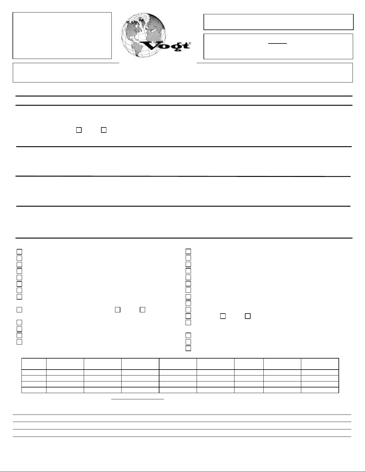
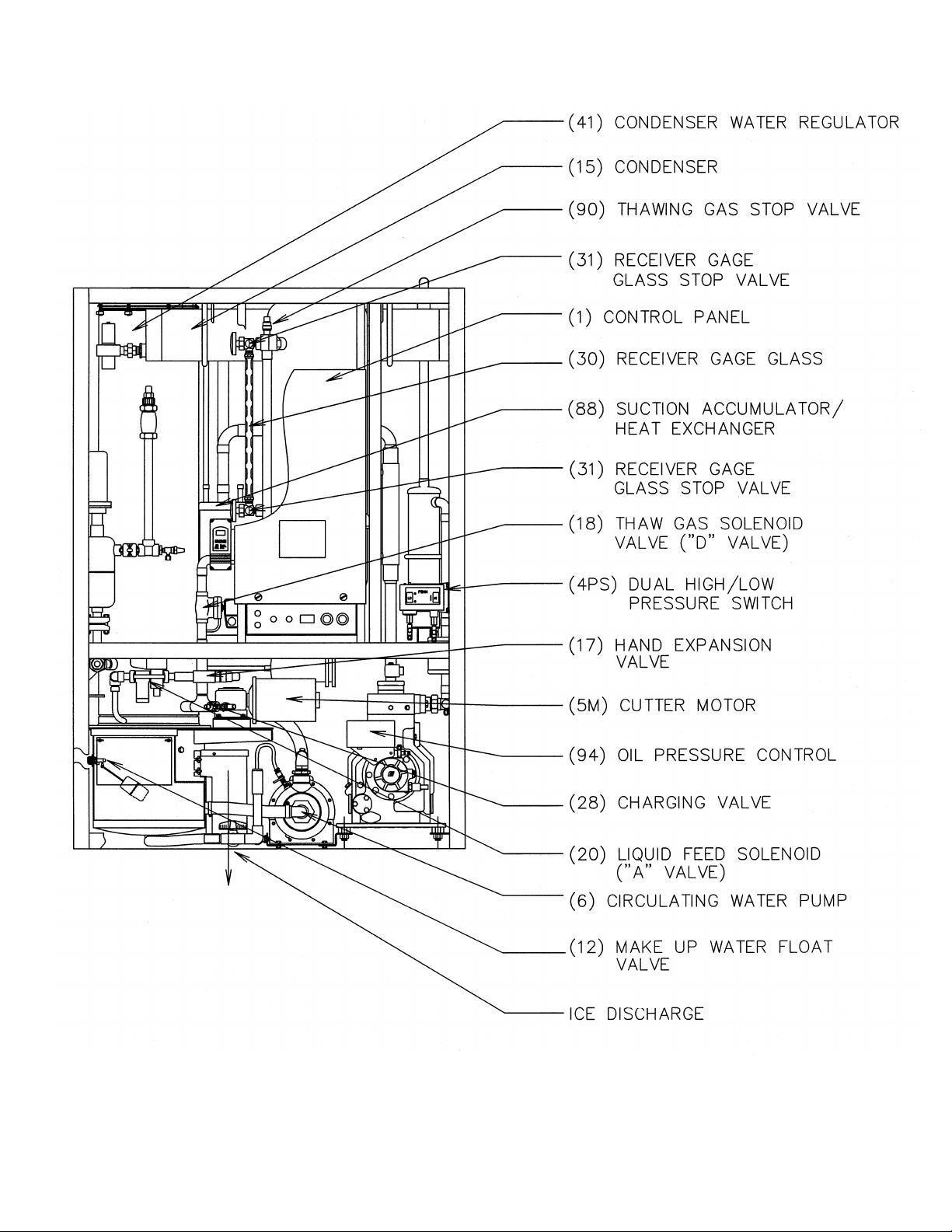
FIGURE 1-1
Assembly (Air-Cooled)
Front View
Page 12
03TA Service Manual
1-5
INTRODUCTION
9/28/98
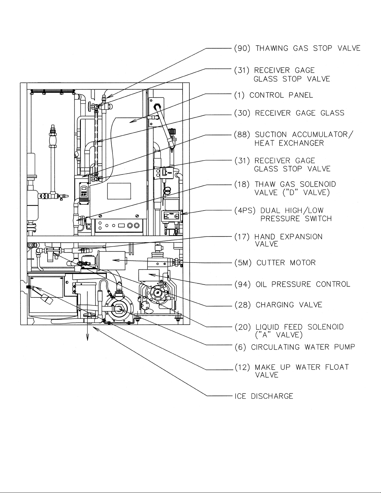
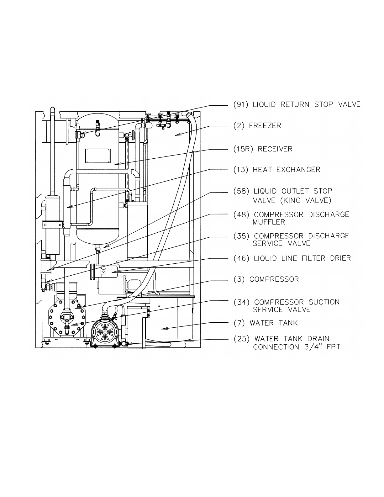
FIGURE 1-2
Assembly (Air-Cooled)
Rear View
Page 13
1-6
INTRODUCTION
03TA Service Manual
9/28/98
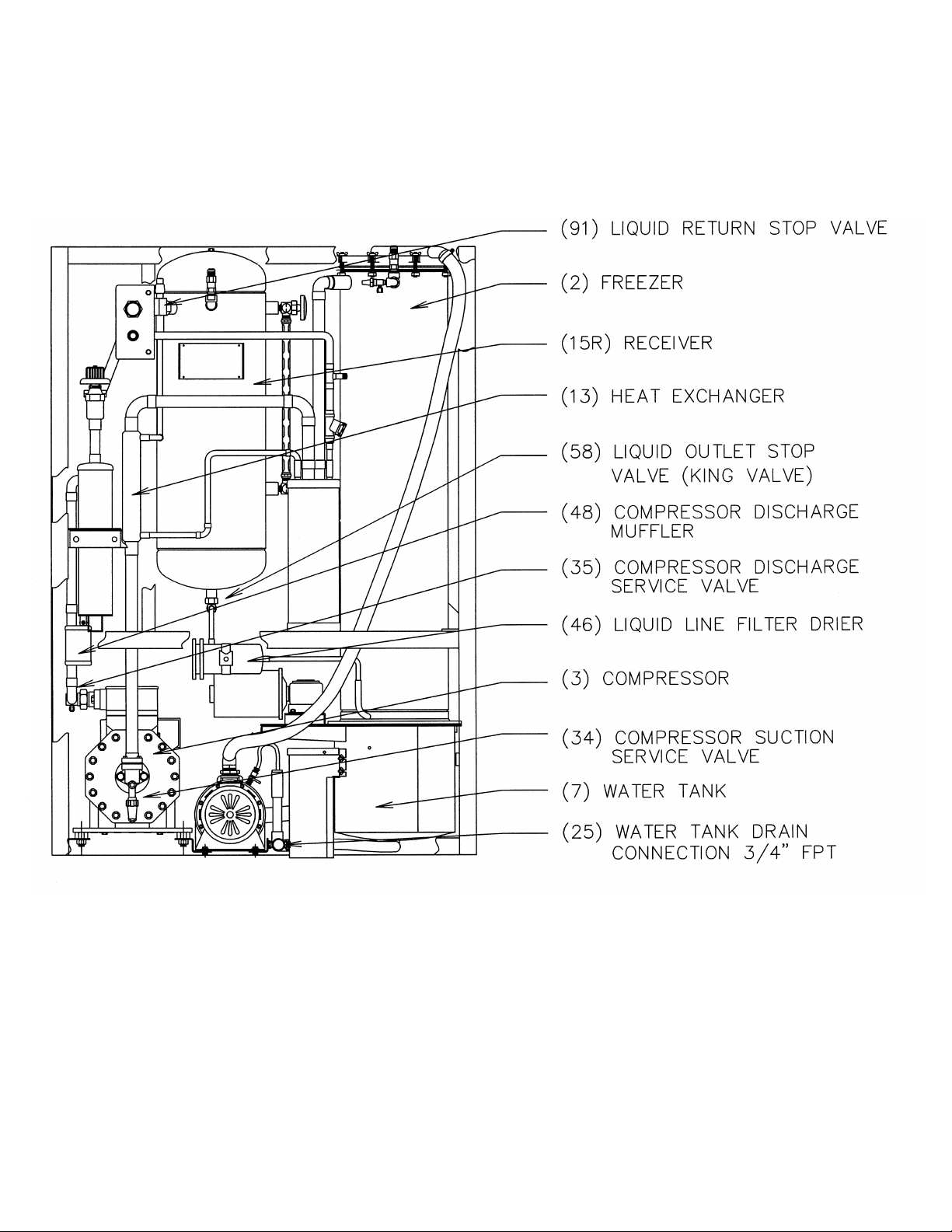
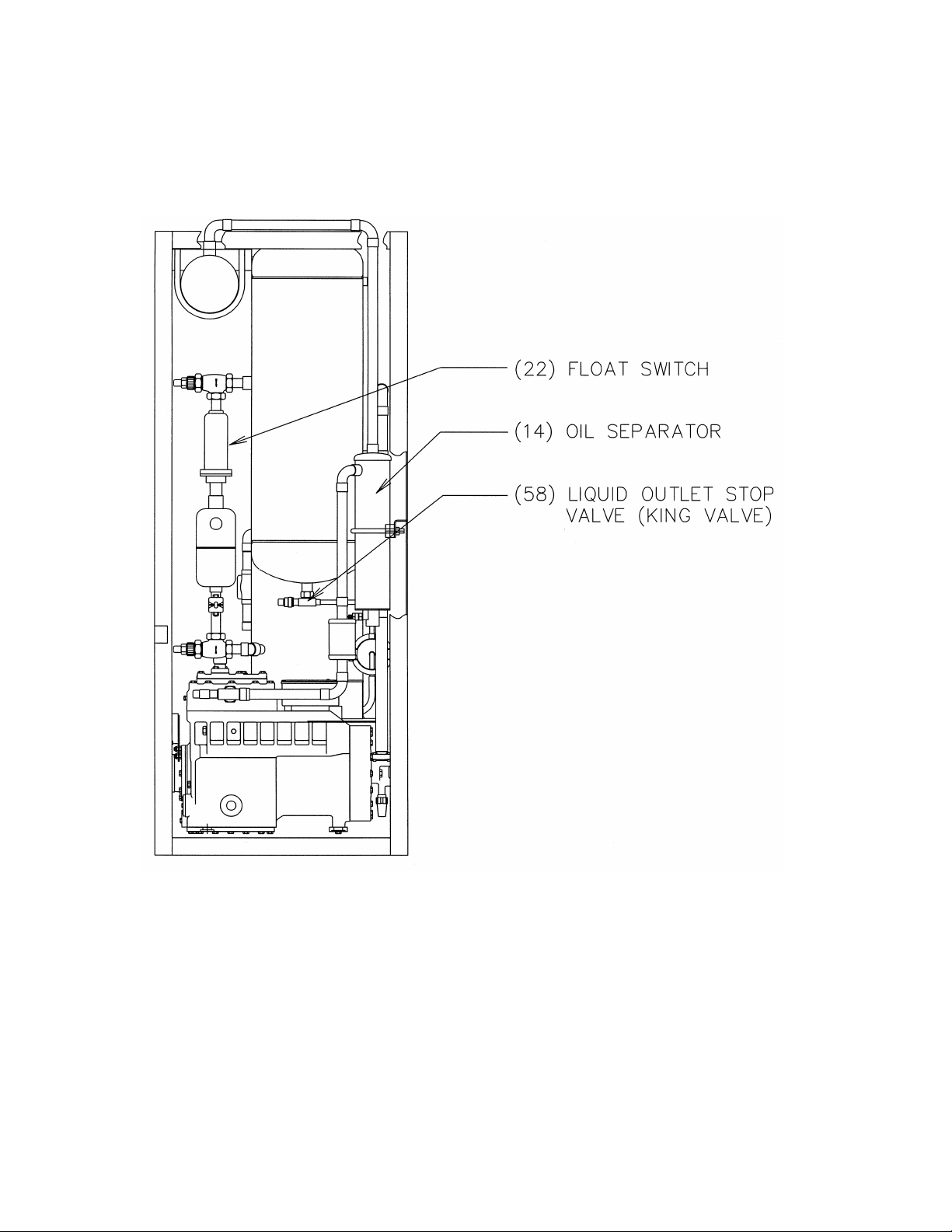
FIGURE 1-3
Assembly (Air-Cooled)
Right Side View
Page 14
03TA Service Manual
1-7
INTRODUCTION
9/28/98
FIGURE 1-4
Assembly (Water Cooled)
Front View
Page 15
1-8
INTRODUCTION
03TA Service Manual
9/28/98
FIGURE 1-5
Assembly (Water Cooled)
Rear View
Page 16
03TA Service Manual
1-9
INTRODUCTION
9/28/98
FIGURE 1-6
Assembly (Water Cooled)
Right Side View
Page 17

03TA Service Manual
RECEIPT OF YOUR TUBE-ICE MACHINE
2. Receipt Of Your Tube-Ice Machine
! WARNING !
Only service personnel experienced in refrigeration and qualified
to work with high voltage electrical equipment should be allowed
to install or work on this Tube-Ice® machine.
! WARNING !
Inspection As soon as you receive your machine, inspect it for any damage. If damage is suspected,
note it on the shipper’s papers (i.e., the trucker’s Bill of Lading). Immediately make a separate
written request for inspection by the freight line’s agent. Any repair work or alteration to the
machine without the permission of TUBE ICE, LLC can void the machine’s warranty.
The machine was shipped with a full charge of refrigerant stored in the receiver. Visually check all
lines for mechanical damage. If a leak is suspected, check all joints with a Halogen Leak Detector.
All leaks should be reported to TUBE ICE, LLC to obtain authorization for repair.
2-1
! CAUTION !
The approximate weight of the machine is 2000 pounds. Always use
equipment with adequate load carrying capacity.
! CAUTION !
The machine frame has lifting lugs at each corner in the top for eyebolts and hooks to be used for
lifting purposes if desired. Lifting lugs should be used whenever possible.
! CAUTION !
The Tube-Ice® machine is top heavy.
Secure to avoid tipping.
! CAUTION !
If a forklift is used, make sure its capacity is sufficient. The forks must be wide enough apart to
prevent tipping sideways and must extend beyond the extremities of the frame base structure. The
machine needs to be bound in place to prevent tipping.
Safety Valves Two safety pressure relief valves are an integral part of the packaged Tube-Ice
machine. One is located in the low-side of the system on the freezer, and one is in the high side of the
system on the receiver. Vent each of the pressure relief valves to the atmosphere in such a manner as
to comply with local and national codes.
®
9/28/98
Page 18

2-2
RECEIPT OF YOUR TUBE-ICE MACHINE
Machine Room The machine must be located inside a suitable building and must not be subjected to
ambient temperatures below 50°F (10°C) or above 110°F (43.3°C). Heat from other sources
(sunlight, furnaces, condenser, etc.) and unusual air currents may affect the operation of the machine
and should be avoided. The electrical components of the Tube-Ice® machine are rated NEMA 1.
Therefore, the machine should not be located in a hazardous area or sprayed with water. The
machine should be installed on a drainable condensate drip pan or in an area where water will not
stand but will readily drain away from the machine. See Space Diagram for clearances and utility
connections, FIGURES 3-1 and 3-2.
Storage (prior to installation or start-up) The machine must not be stored or installed in an area
that may reach temperatures 115°F (46.1°C) or above.
This equipment contains HCFC-22 or HFC-404a refrigerant under pressure.
Do not store in an area exposed to temperatures above 115°F (46°C)
or in direct sun at temperatures above 105°F (40°C).
03TA Service Manual
! CAUTION !
! CAUTION !
9/28/98
Page 19
03TA Service Manual
4'-2"
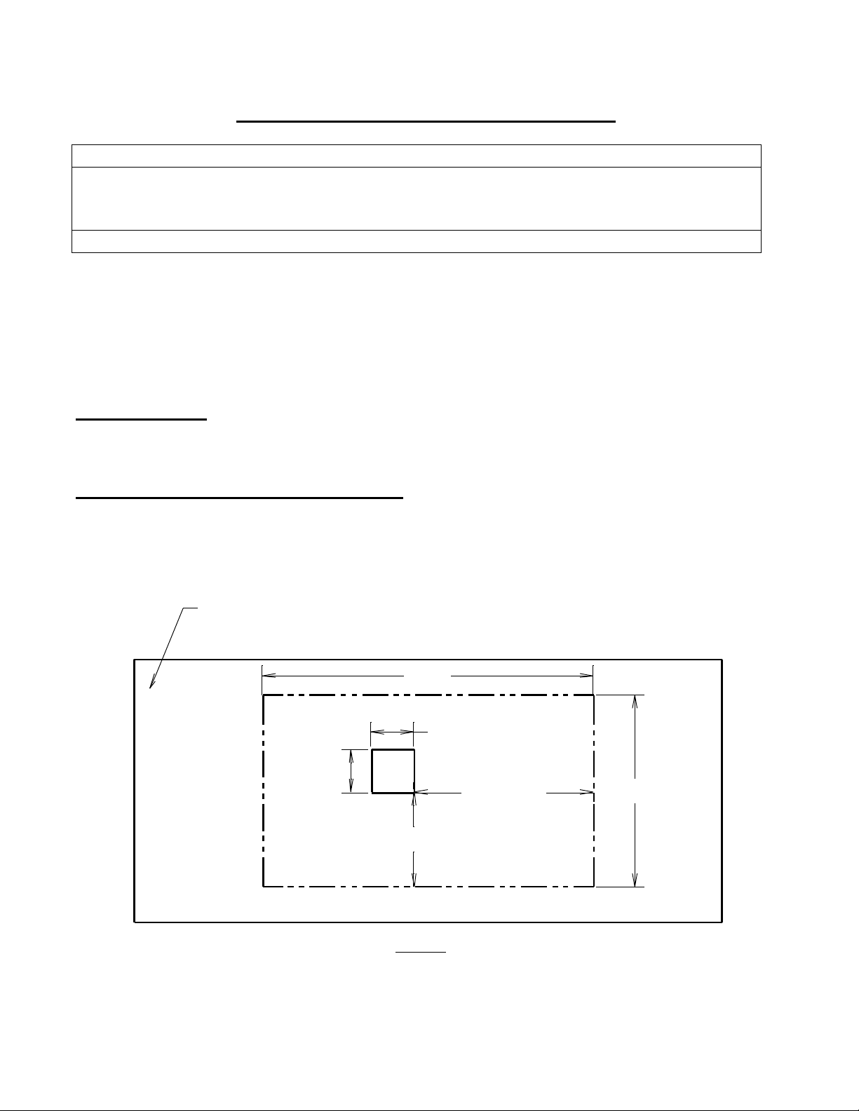
PLAN
MINIMUM BIN OPENING - 6 1/2" x 6 1/2"
MAXIMUM BIN OPENING - 7" x 7"
FRONT OF MACHINE
3-1
INSTALLING YOUR TUBE-ICE® MACHINE
3. Installing Your Tube-Ice
! WARNING !
Only service personnel experienced and certified in refrigeration and qualified to work
with high voltage electrical equipment should be allowed to install or work
on this Tube-Ice® machine.
! WARNING !
®
Machine
Important Notice.
The Warranty Registration / Start-Up Form must be completed and returned to
Vogt Tube-Ice® to initiate and assure a full warranty. A postage paid envelope is
provided or you may fax the report to 800-770-8648.
Bin Installation Set the bin on solid, level footing. Inside the bin you will find the four legs.
Screw these legs to the bottom of the bin. You can make MINOR leveling adjustments by using
these legs as leveling screws, as outlined in the manufacturer’s instructi ons.
Setting the ice machine on the ice bin Once the ice storage bin is level, the Tube -Ice
machine can be elevated and placed on the bin top. Using the dimensions in FIGURE 3 -1 below,
mark the machine footprint on the bin top by measuring over from the ice chute opening.
®
ICE BIN
CHUTE SIZE - 5 5/8" X 5 5/8"
6 1/2"
6 1/2"
2'-3 1/16"
2'-5"
1'-2 1/4"
FIGURE 3-1
Ice Chute Location/Machine Footprint
8/23/01
Page 20
3-2
INSTALLING YOUR TUBE-ICE® MACHINE
03TA Service Manual
FIGURES 3-2 & 3-3 illustrate two methods of lifting & setting Tube - Ice? machine on an ice storage bin.
! CAUTION !
The approximate weight of the machine is 2000 pounds.
Always use equipment with adequate load-carrying capacity.
! CAUTION !
REMOVE CASINGS FROM MODEL HE60
BEFORE PLACING MACHINE ON BIN
CONTROL PANEL
& SWITCH BOX
TUBE-ICE MACHINE
WOOD BLOCKS
TWO (2) EACH CORNER
ICE STORAGE BIN
FIGURE 3-2
Forklift-&-Blocks Method
You need:
??forklift truck with adequate load and height capacities
??(8) 2X4 wood blocks 8 in. long
??(2) wooden 2X4’s measuring 3-ft. long
??pry bar
Step 1. Position Tube-Ice? machine on forks.
Step 2. Stack wood blocks in each corner of the drip pan on top of the ice storage bin.
Step 3. Lift and set Tube-Ice? machine on wood blocks.
Step 4. Remove forklift.
Step 5. Stack 3-ft. long 2X4’s beside drip pan, overlapping front and back of bin.
Step 6. Using a pry bar with fulcrum on 2X4’s, raise side of machine enough to remove TOP wood
blocks.
! CAUTION !
Do not remove top AND bottom blocks at the same time.
! CAUTION !
Step 7. Repeat steps 5 and 6 on other side.
Step 8. With machine sitting on one (1) block under each corner, repeat steps 5, 6, and 7 remove
remaining blocks. Drip pan flanges may bend slightly.
Step 9. Straighten bent drip pan flanges.
Step 10. Check alignment of ice chute to bin opening.
8/23/01
Page 21
03TA Service Manual
BEFORE PLACING MACHINE ON BIN
INSTALLING YOUR TUBE-ICE® MACHINE
REMOVE CASINGS FROM MODEL HE60
ROPE OR STRAPS
TUBE-ICE MACHINE
ICE STORAGE BIN
3-3
FIGURE 3-3
Forklift-&-Rope or Lifting Straps Method
You need:
??extra head room
??forklift with adequate load and height capacities
??1/2” rope or four lifting s traps to bind forks to top angles
Step 1. Remove front, rear, and top access panels.
Step 2. Position fork truck so that forks are resting flat on top angles of Tube -Ice®
machine.
Step 3. Use the rope or straps to securely bind forks to the top angles.
! CAUTION !
Be sure the bin is level and is set in its proper location.
See the space diagram, FIGURE 6.
! CAUTION !
Step 4. Lift Tube-Ice® machine and set into drip pan of bin.
Step 5. Remove rope or straps and fork truck.
Step 6. Check alignment of ice chute to bin opening.
8/23/01
Page 22
8/23/01
INSTALLING YOUR TUBE-ICE
3-4
Connections and Space Diagram (Air Cooled Machine)
®
MACHINE
FIGURE 3-4
03TA Service Manual
Page 23
8/23/01
03TA Service Manual
Connections and Space Diagram (Water Cooled Machine)
FIGURE 3-5
INSTALLING YOUR TUBE-ICE
®
MACHINE
3-5
Page 24

3-6
Condenser
INSTALLING YOUR TUBE-ICE® MACHINE
Piping and Drain Connections
Figure 3-4 (Air Cooled) and 3-5 (Water Cooled) show locations and sizes for all connections.
External shut-off valves must be provided in the water inlet lines.
The minimum inlet water pressure for satisfactory operation of the machine is 30 psig.
The maximum allowable pressure is 100 psig.
Make-up
Water In
1/2” MPT 3/4” FPT 1 1/4” FPT 1 1/4” FPT
* The condenser water outlet and water tank drain connections must be extended to an open drain or
sump, arranged for visible discharge. Do not trap the water tank drain line, as this will interfere
with the operation of the automatic blowdown system. A 20 mesh strainer, supplied with the
machine, should be installed in the supply line to the condenser.
These lines must NOT be connected into a pressure tight common header
due to the possibility that warm condenser water may back up into the water tank.
The condenser water outlet MUST be piped separately to the drain.
Cooling Tower.
For water cooled machines only. When selecting a cooling tower, careful attention must be given to
operating wet bulb conditions. It is advisable to check with your local cooling tower distributor for
their recommendations based on actual operating conditions in your area. An average wet -bulb of
78?F is typical in the U.S. but many localities have design wet - bulbs as low as 72?F or as high as
82?F.
The cooling tower water pump must be capable of deliveri ng the required volume of water through
the condenser. Due to cooling tower location and pressure drop through water lines and water
regulating valves, the pump must be sized for each installation. Refer to TABLE 11 -4 for condenser
water requirements. The water piping for the cooling tower and the installation of the pump must be
in accordance with the manufacturer’s instructions.
Proper water treatment for the prevention of mineral and foreign matter accumulation in the
condenser or cooling tower is recommended. A water analysis should be obtained to determine the
proper chemicals to use.
! CAUTION !
! CAUTION !
Water Tank
Drain*
Condenser
Water In
TABLE 3-1
Water Supply and Drain Sizes
! CAUTION !
! CAUTION !
03TA Service Manual
Water Out*
8/23/01
Page 25
03TA Service Manual
INSTALLING YOUR TUBE-ICE® MACHINE
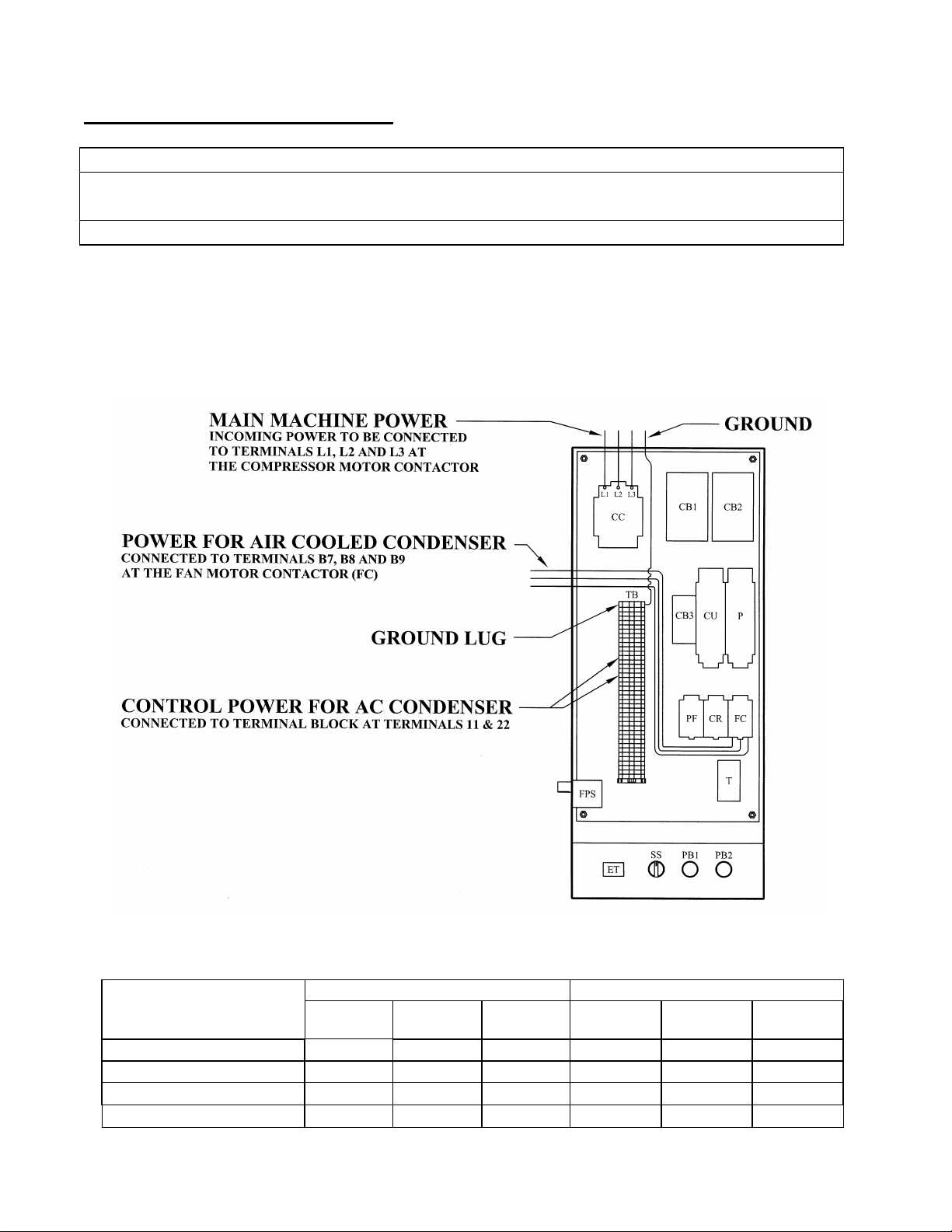
Wiring and Electrical Connection
! WARNING !
Only service personnel experienced in refrigeration and qualified to work with high voltage
electrical equipment should be allowed to install or work on the Tube-Ice® machine.
! WARNING !
Refer to TABLE 3-2 below to properly size wiring connections. A fused disconnect must be
provided near the Tube- Ice® machine. Connect 3 phase power to terminals L1, L2, L3 for operation
of the Tube-Ice® machine and its controls. Rotation checking of cutter motor and water pump is
required (see following section). Also, if one leg of the 3 phase power is higher or lower (“Wild”),
then it should be connected to terminal #L2. Connect the “Ground” wire to the “Ground” lug
provided.
3-7
8/23/01
FIGURE 3-6
Control Panel Power Connections
Water Cooled Air Cooled
Standard Voltages
208/230, 3ph, 60 Hz 66.9 81.8 145 76.9 91.8 155
460, 3ph, 60 Hz 32.7 39.9 70 37.2 44.4 75
200, 3ph, 50 Hz 73.3 89.8 160 83.3 99.8 170
400, 3ph, 50 Hz 37.2 45.4 80 42.2 50.4 85
F.L.A. Min.
Ampacity
Max. Fuse F.L.A. Min.
Ampacity
Max. Fuse
TABLE 3-2
Page 26

3-8
INSTALLING YOUR TUBE-ICE® MACHINE
Phase Check
DO NOT attempt to start machine without priming pump
and insuring proper rotation of both cutter and pump.
Refer to FIGURE 3-1 & 3-2 (space diagram) for connection locations.
Cutter and pump motor rotation are factory synchronized but must be checked at installation. For ice
production, the cutter disc, as viewed at the ice discharge opening should turn from left to right
(crushed rotation should be from right to left). The pump rotation should match the marking on the
pump housing. The pump will need to be primed by starting the machine in the clean mode and
allowing it to run for several minutes. To change direction of rotation for both, cutter and pump,
disconnect power and reverse L1 and L3 (incoming power wires) at the compressor motor contactor.
Voltage Unbalance Voltage unbalance can cause motors to overheat and fail.
The maximum voltage unbalance between any two legs should be no greater than 2%.
Example: Supply Voltage = 230-3-60
Voltage Readings: AB = 220 Volts
BC = 225 Volts Average = (220 + 225 + 227)/3 = 224 Volts
AC = 227 Volts
(AB) 224-220 = 4 Volts (Highest Deviation)
(BC) 225-224 = 1 Volts % Voltage Unbalance = 100 x (4/224) = 1.78%
“Acceptable”
(AC) 227-224 = 3 Volts
Important: If the supply voltage phase unbalance is more the 2%, contact your local electric
utility company.
Current Unbalance Voltage unbalance will cause a current unbalance, but a current unbalance
does not necessarily mean that a voltage unbalance exists. A loose terminal connection or a buildup
of dirt or carbon on one set of contacts would cause a higher resistance on that leg than on the other
two legs. Current follows the path of least resistance, therefore if terminal connection L1 is loose or
dirty, L2 and/or L3 will have higher current. Higher cu rrent causes more heat to be generated in the
motor windings.
The maximum acceptable current unbalance is 10%.
Example:
Current Readings: L1 = 96 Amps
L2 = 91 Amps Average = (96 + 91 + 98)/3 = 95Amps
L3 = 98 Amps
(L1) 96-95 = 1 Amps
(L2) 95-91 = 4 Amps (Highest Deviation) % Current Unbalance = 100 x (4/95) = 4.2%
“Acceptable”
(L3) 98-95 = 3 Amps
8/23/01
03TA Service Manual
Electrical Specifications
! CAUTION !
! CAUTION !
Page 27

03TA Service Manual
INSTALLING YOUR TUBE-ICE® MACHINE
Air-Cooled Condenser Installation Instructions
! WARNING !
These installation guidelines must be followed to obtain
reliable operation from air cooled ice machines.
IF THESE GUIDELINES ARE NOT FOLLOWED THE
COMPRESSOR WARRANTY WILL NOT BE HONORED.
! WARNING !
1. Use only Vogt approved condensers. Any exceptions to this policy must be obtained in writing
from Vogt prior to installation and operation of the ice machine.
2. Outdoor condensers must be installed with vertical air flow. Indoor condensers used for heat
recovery may be installed with either horizontal or vertical air flow.
3. The condenser must be mounted above the ice machine.
4. Horizontal runs in the liquid return line should slope 1/4” per foot with liquid refrigerant draining
freely in the direction of normal operating flow (back to the ice machine) with no traps in the
liquid line.
5. Horizontal runs in the discha rge line should slope 1/4” per foot in the normal direction of flow
(away from the ice machine).
6. Traps must be installed in discharge lines at the base of all vertical risers. There should be no
intentional traps in liquid lines. Trap volume should be kept to a minimum. Long vertical rises
should have traps every 20 feet. Typical details are shown in FIGURE 3 -7.
7. Flooding head pressure controls such as Alco Headmaster are not to be used since they cause
excessive subcooling of the returned liquid refrigerant and interfere with reliable ice harvest.
8. The discharge and liquid lines must be insulated with 1/2” thick Armaflex insulation or equal.
9. Use only ACR grade copper pipe, Type L. Recommended line sizes are shown in TABLE 3-3.
10. For field attachment instructions, see FIGURE 3-4.
11. Distance between ice machine and condenser must not exceed 150 equivalent feet. Refer to
Condenser Equivalent Line Size worksheet (see TABLE 3 -4 ).
12. Condensers must be provided with a cold weather valve kit per FIGURE 3-8. These valves allow
one-half of the condenser to be disabled in cold weather. Running the ice machine with one-half
of the condenser in cold weather makes it easier to maintain minimum necessary condensing
pressure particularly in windy conditions.
13. Condensers with multiple fans must be provided with a thermostat to turn off unneeded fans in
cold weather. Turning off unneeded fans reduces on-off cycling of the fan(s) and allows for a
steadier condensing pressure and more consistent warm gas for ice harvesting.
3-9
8/23/01
Page 28

3-10
INSTALLING YOUR TUBE-ICE® MACHINE
14. When extreme cold conditions are expected or encountered (temperatures below 0?F and wind
greater than 15 MPH), it may be necessary to install a protective enclosure around the condenser.
Apparatuses such as louvers may also be used for varying conditions. Contact the factory for
suggestions.
15. After installation, the field installed lines are to be evacuated to a vacuum of 500 microns or less
and held for at least one hour. After the vacuum pump is removed, vacuum should hold at 500
microns or less for at least 5 minutes.
16. The machine is shipped with a full operating charge of refrigerant sufficient to fill the condenser
and connecting lines. If the condenser piping is longer than 50 feet (one way), additional R -22 or
R-404a may need to be added to retain enough refrigerant in the receiver for thawing purposes
(see table. Refer to the operating level mark on the receiver and charge accordingly. Each 1” of
liquid level in the receiver equals approximately 5.5 pounds of R -22 or R-404a.
Liquid Line Size 75 ft. 100 ft. 125 ft. 150 ft.
1/2” none None None 2
5/8” none 2 4 6
7/8” none 4 8 12
1-1/8” none 6 12 18
Pounds of R-22 to Add vs. Liquid Line Length
17. All piping must be done in accordance with applicable local and national codes. Su ch codes may
include “The Safety Code For Mechanical Refrigeration” (ANSI B9.1) and “The Code For
Refrigerant Piping” (ANSI B31.5).
18. The following installation guidelines are strongly suggested. While they do not affect the machine
warranty, they may be required for safe operation and to comply with all applicable electrical and
mechanical codes:
a. Local electrical code must be checked for wiring method.
b. The installer must provide a disconnect switch(s) adjacent to the condenser.
c. Electrical conn ections between the condenser and the Tube- Ice® machine require
minimum 12 ga. wire.
d. All electrical fittings and components exposed to the weather must be suitable for
outdoor installation.
The design total heat rejection for each Tube -Ice® machine, the recommended air -cooled condenser,
and condenser physical and electrical data are shown on the next page. Specified energy efficiency
ratings of the ice machines are based on use of the recommended condenser and approved piping
practices.
Recommended condensers provide the indicated total heat rejection at 90?F ambient, 100?F
condensing. Tube Ice, LLC is not responsible for head pressure problems if other than the
recommended condensers are used. For continuous operation at ambient temperature above 105 ?F,
consult the factory about using a larger condenser.
03TA Service Manual
TABLE 3-3
8/23/01
Page 29

03TA Service Manual
Ice Machine Model 03TA 03TA
Electrical Frequency, Hz. 60 50
Recommended Condenser DD-231 DD-231
Total Heat Rejection (BTU/hr) 128,100 128,100
Fans:
Number
HP, Each
Total CFM
Full Load Amps (FLA):
3 ph., 208/230V, 60 hz.
3 ph., 460V, 60 hz.
3 ph., 200V, 50 hz.
3 ph., 380V, 50 hz.
Locked Rotor Amps (LRA):
3 ph., 208/230V, 60 hz.
3 ph., 460V, 60 h z.
3 ph., 200V, 50 hz.
3 ph., 380V, 50 hz.
Weight, lbs.:
Net
Shipping
Operating (Maximum flooded) R-404a
Condenser Dimensions, inches (See Fig. 3-7)
A (Width)
B (Length)
C (Height)
D (Leg centerline)
E (Leg centerline)
F (Clearance below)
Recommended Line Sizes, OD
Liquid
All lengths and orientations
Discharge Gas
Vertical Up, all lengths
Horiz. or Down, < 75 ft.
Horiz. or Down > 75 ft.
Connections (Cond. & Ice Mach.):
Liquid (ODF)
Discharge Gas (ODF)
3
1/2
15,000
6.0
3.0
--
--
19.8
9.8
--
--
400
500
430
41 3/8”
105”
36 1/8”
40 3/8”
94”
11 3/4”
1 1/8”
1 1/8”
1 1/8”
1 3/8”
1 1/8”
1 3/8”
TABLE 3-4
Air-Cooled Condenser Data
3-11
INSTALLING YOUR TUBE-ICE® MACHINE
3
1/2
15,000
--
--
6.0
3.0
--
--
19.8
9.8
400
500
430
41 3/8”
105”
36 1/8”
40 3/8”
94”
11 3/4”
1 1/8”
1 1/8”
1 1/8”
1 3/8”
1 1/8”
1 3/8”
8/23/01
Page 30
3-12
INSTALLING YOUR TUBE-ICE® MACHINE
03TA Service Manual
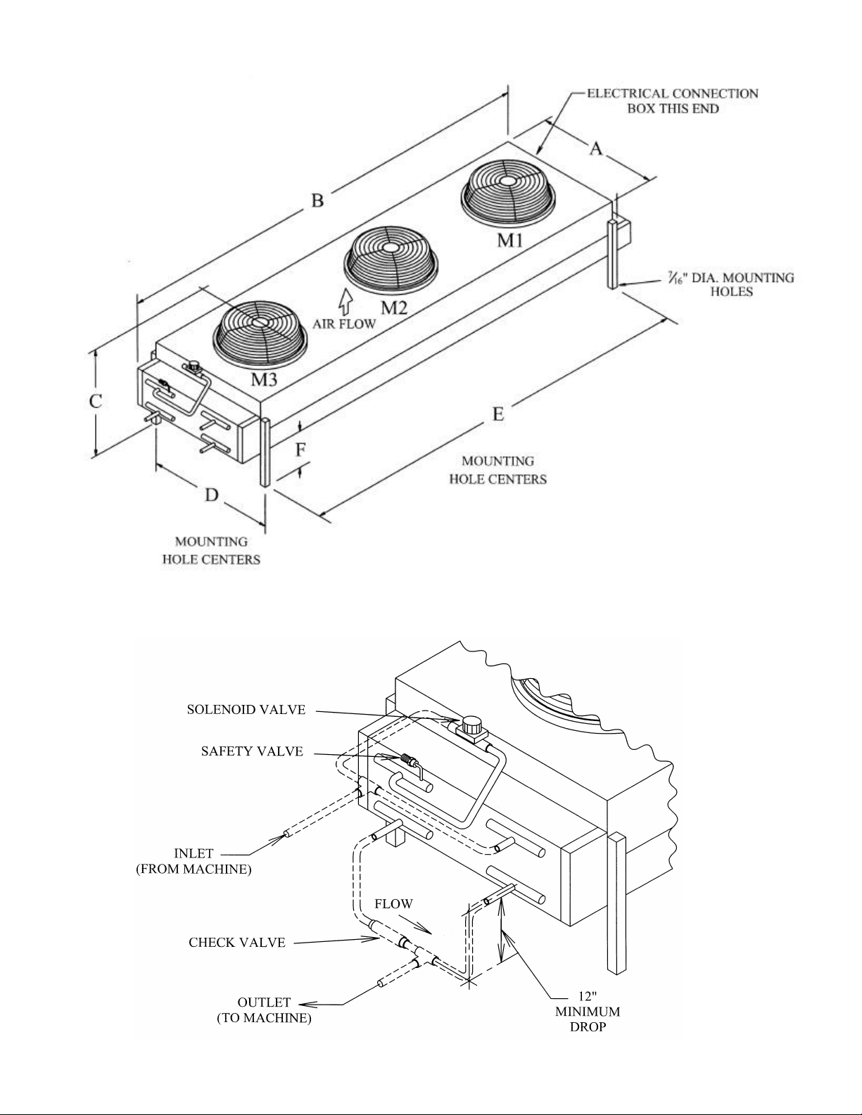
FIGURE 3-7
Condenser Dimensions (Condenser pictured: DD-231)
Note: Dash lines indicate customer supplied piping.
8/23/01
FIGURE 3-8
Condenser Field Piping (Cold Weather Valve Kit)
Page 31

03TA Service Manual
Fitting Type
Number Used
Factor
Total
90? Elbow
45? Elbow
Tee
Tee (90
?
turn through)
2 2.5 2.8 3.5
CONDENSER EQUIVALENT LINE SIZE WORKSHEET
3-13
INSTALLING YOUR TUBE-ICE® MACHINE
Discharge Gas Line O.D. ___________________
Globe Valve (open)
Angle Valve (open)
Feet of Straight Copper Used
Total Fitting Factor
Total Equivalent Feet
Copper Tubing Type “L” 1 1/8” O.D. 1 3/8” O.D. 1 5/8” O.D. 2 1/8” O.D.
Globe valve (open)
Angle valve (open)
90o Elbow
45o Elbow
28 36 42 57
15 18 21 28
3 4 4 5
1.5 2 2 2.5
6 8 9 12
Tee (straight through)
TABLE 3-5
Equivalent Feet Due To Friction
*Note: Each recommended line size is based on use of Type “L” copper tubing at a maximum
equivalent distance of 150 feet. See TABLE 3 -5 for equivalent feet of valves and fittings.
8/23/01
FIGURE 3-9
Minimum Traps For Discharge Lines
Page 32

3-14
Spud Size
Amount of Torque
7/8” 50-60 FT LBS
1 1/8”
80-
100 FT LBS
1 3/8”
100-110 FT LBS
INSTALLING YOUR TUBE-ICE® MACHINE
Air-Cooled Condenser Wiring
03TA Service Manual
FIGURE 3-10
Wiring For #DD-231 and #DD-261 Condenser
(3 phase motors)
Air-Cooled Connections (See FIGURE 3-4 for connection sizes)
Follow these procedures to make a tight joint:
1. Silver solder or braze condenser tubing ends to the female Rota- lock connectors.
2. Remove dust caps if used, making sure that component plastic seals are intact.
3. Wipe off connector and spud threaded surfaces with a clean cloth to prevent the inclusion
of dirt or any foreign material in the system.
4. Connector coupling nut should be screwed onto Rota-lock spud using the proper amount
of torque.
TABLE 3-6
Rota-lock Connector Torque Ratings
8/23/01
Page 33

03TA Service Manual
INSTALLING YOUR TUBE-ICE® MACHINE
Ice Bin Thermostat Sensor Installation Each machine is equipped with an electronic ice bin
thermostat. To assure proper protection for the machine, the sensor of the ice bin thermostat must be
located so that ice will contact it when the bin is full (See FIGURE 3 -11). The distance between the ice chute
and the sensor allows space for the machine to make an additional discharge of ice AFTER the ice contacts
the probe WITHOUT the ice building up into the discharge opening of the chute.
Note: The probe should also be mounted on the back side of the bracket, opposite of the front of the bin to
reduce the possibility of damage from ice removal equipment.
The control panel is electrically connected so that the bin thermostat will stop the machine only upon the
completion of a harvest period.
When both cylinder and crushed ice are produced and separately stored in a divided bin, the control sensor of
thermostat BT2 is placed in the crushed ice section of the storage bin (left side) and the control sensor of
thermostat BT1 is placed in the cylinder ice section (right side of bin).
3-15
8/23/01
Note: Drip loop not necessary for Electronic Thermostat
FIGURE 3-11
Ice Bin Thermostat Location
Programming the Electronic Bin Thermostat
Page 34

3-16
READING
CONNECTION
CONNECTION
INSTALLING YOUR TUBE-ICE® MACHINE
The electronic bin thermostat has an LCD readout that displays the temperature in the bin at the sensor. The
control has been preset and locked out at the factory to shut the machine down at 38?F and to re-start
at 40?F. The control retains the program even if power is cut to the machine. Under special conditions, the
settings may need to be changed. The lockout switch is located on the inside of the control. Removal of the
four screws on the face of the control will reveal the lock -switch.
Follow the instructions below to reset the switch.
1. Press the “SET” button to enter the sensors setup mode
2. Select between “C”- Celsius and “F” - Fahrenheit
Use the up ? or down ? key to select “F”
3. Press the “SET” button to set the Set point (S1 will be blinking)
Use the up ? or down ? key to set the temperature at 38?F
4. Press the “SET” button to set the Differential (DIF 1 will be blinking)
Use the up ? or down ? key to set the differential at 2?F
5. Select between “C1”- Cooling mode and “H1” - Heating mode
Use the up ? or down ? key to select “C1”
Machine will shut off when temperature drops to 38°F and come on when temperature reaches 40°F.
03TA Service Manual
Note: The sensor will automatically exit the programming mode if no keys are depressed for a period of thirty
seconds. Any settings that have been input to the control will be accepted at that point.
DIGITAL TEMPERATURE
SENSOR
SENSOR POWER
CONTROL CIRCUIT
FIGURE 3-12
Electronic Thermostat
Note: If damaged, the sensor can be replaced without replacing enti re unit.
Replacement sensor part #12A 2117G0901. Electronic temperature control part #12A 2117G09.
Sensor cable can be extended up to 400 feet. For more information, consult Tube-Ice® Technical
Service Department.
8/23/01
Page 35

03TA Service Manual
HOW YOUR TUBE-ICE MACHINE WORKS
4. How Your Tube-Ice® Machine Works
Principle of Operation For a detailed description of the functions of each control panel component,
see Section 6. Operation of the machine is controlled by “Ice/Clean”, “On/Off”, “Start” and “Stop”
switches located in the control panel of the freezing unit. Automatic operation is controlled by an
ice bin thermostat which will automatically stop and start the ice maker by the level of the ice in the
storage bin (NOTE: See FIGURE 3-11, “Ice Bin Thermostat Location” for instructions on
installation of the control sensor of the ice bin thermostat(s)). The type ice produced (cylinder or
crushed) is determined by how the machine cutter is set-up (cylinder is standard, crushed is
optional). The control wiring is arranged so that the unit will stop only upon the completion of a
thawing period whether by action of the “Off” switch or the ice bin thermostat.
The “Ice/Clean” switch must always be set in the “Ice” position during normal ice-making operation.
It is set in the “Clean” position only when the equipment is to be cleaned as outlined in the
“Cleaning Procedure” (Section 7) and instructions attached to the machine.
4-1
If it should become necessary to instantly stop the machine, push the “Stop” button. To restart the
machine, push the “Start” button. The machine will restart in a harvest, to clear out any ice
remaining in the freezer, if stopped during a freeze period.
FIGURES 4-1 & 4-2 illustrate the piping diagram of the refrigerant and water circuits of the TubeIce® machines with numbers for easy reference. Throughout this manual, the numbers you see in
parentheses refer to the numbers in this piping schematic.
The freezer (2) is a shell and tube-type vessel. During the freezing period, water is constantly
recirculated through the vertical tubes of the freezer by a centrifugal pump (6). Make-up water is
maintained by a float valve (12) in the water tank (7). The liquid feed solenoid valve (20),
sometimes referred to as the “A” valve, is open and the thawing gas solenoid valve (18), sometimes
referred to as the “D” valve, is closed.
Refrigerant gas from the top of the freezer (2) passes through the suction accumulator (88), the heat
exchanger (13), and to the compressor (3). Here the cool gas is compressed to a high temperature,
high pressure gas which discharges through the oil separator (14) and into the condenser (15). In the
condenser, heat is removed and the gas is condensed to a high temperature, high-pressure liquid.
The high-pressure liquid goes through the accumulator boil out coil (88) and suction line heat
exchanger (13) where it is gives up heat to the suction gas for compressor protection. In addition,
this liquid is subcooled and carried to the receiver (15R). Condensed liquid refrigerant from the
receiver flows through the filter/drier (46), thawing chamber (16), liquid feed solenoid valve (“A”
valve) (20) and hand expansion valve (17) into the freezer. The float switch (22) is wired to the “A”
solenoid valve (20). The float switch energizes and de-energizes the “A” solenoid in response to the
level of refrigerant in the freezer. The cold liquid refrigerant enters the freezer where it absorbs heat
from the circulating water. This cool gas is pulled out of the freezer at the suction outlet thereby
completing the circuit.
09/23/98
The freezing period is completed by action of the freezer pressure switch in the control panel. The
water pump (6) is stopped and solenoid valve “A” (20) is closed. The thawing period then begins.
Solenoid valve “D” (18) is opened, the cutter motor (5M) is started and the harvest (thaw) timer is
activated. Warm gas from the receiver is discharged into the freezer through valve (18), thereby
Page 36

4-2
HOW YOUR TUBE-ICE MACHINE WORKS
slightly thawing the outer edge of the ice, which drops on the rotating cutter for sizing. See “Freeze
Period and Harvest Period” in this section for a more detailed description of these operations.
Air-cooled machines have a solenoid valve (53), sometimes referred to as the “X” valve, in the
compressor discharge line, and a check valve (101) in the liquid return line to the receiver. These
valves prevent the migration of refrigerant to the compressor when the machine is not operating.
Freeze Period The Tube-Ice® is frozen inside the stainless steel tubes in the freezer (2) by the direct application of refrigerant to the shell side (outside) of the tubes. The ice is produced from constantly recirculating water during the freeze period. As the ice thickness increases, the freezer suction pressure decreases. At a set pressure, the freezer pressure switch initiates the harvest period.
Harvest Period When the freezer pressure switch (56, FPS) contact closes, a control relay (CR) is energized. The “CR” relay stops the water pump and starts the cutter motor. The “A” (liquid line) solenoid valve closes, the “D” (thaw gas) solenoid valve opens and the thaw timer (T) is energized. As the ice releases and drops through the rotating cutter and onto the cutter disc, it is discharged through the side opening of the water tank. The harvest timer (T) is to be set for the time required to discharge all the ice plus 30 seconds longer (usually 2 1/2 minutes).
03TA Service Manual
! CAUTION !
Make sure all the ice clears the freezer with at least 30 seconds to spare
before the next freeze period begins. This is to prevent refreezing.
! CAUTION !
Item No. Description Item No. Description
1 Control Panel 31 Gage Glass Stop Valve
2 Freezer 32 A/C Condenser Service Connection
3 Compressor 34 Compressor Suction Service Valve
4PS Dual High/Low Pressure Switch 35 Compressor Discharge Service Valve
5M Cutter Motor 37 Oil Charging/Drain Valve
5R Gear Reducer 39 Water Tank Drain Valve
6 Water Pump 40 Automatic Water Tank Blowdown
6A Water Pump Check Valve 41 Condenser Water Regulator (W/C Machines Only)
7 Water Tank (includes cutter assembly) 41A Condenser Pressure Control (A/C Machines Only)
8 Water Distributing Chamber 43 Liquid Feed Solenoid Valve Strainer
12 Make-up Water Float Valve 46 Filter Drier
13 Heat Exchanger 48 Muffler
14 Oil Separator 50 Receiver Safety Valve
15 Condenser 51 Freezer Safety Valve
15R Receiver 52 Condenser Safety Valve
16 Thawing Chamber 53 Cold Weather Solenoid Valve “X” (A/C Machines Only)
17 Hand Expansion Valve 55 Discharge Line Stop Valve (A/C Machines Only)
18 Thawing Gas Solenoid Valve (“D” Valve) 56 Freezer Pressure Switch
20 Liquid Feed Solenoid Valve (“A” Valve) 58 Liquid Outlet Valve (King Valve)
22 Float Switch 69 Freezer Pressure Stop Valve
23 Condenser Water Inlet (W/C Machines Only) 88 Accumulator/Heat Exchanger
24 Condenser Water Outlet (W/C Machines Only) 90 Thawing Gas Stop Valve
25 Water Tank Drain Connection (3/4” FPT) 91 Receiver Liquid Return Stop Valve
28 Refrigerant Charging Valve 94 Compressor Oil Pressure Safety Control
30 Receiver Gage Glass 101 Check Valve
TABLE 4-1
Piping Nomenclature
09/23/98
Page 37

09/23/98
Water-Cooled Piping Schematic
FIGURE 4-1
03TA Service Manual
HOW YOUR TUBE-ICE
MACHINE WORKS
4-3
Page 38

09/23/98
Air-Cooled Piping Schematic
FIGURE 4-2
4-4
HOW YOUR TUBE-ICE
MACHINE WORKS
03TA Service Manual
Page 39

03TA Service Manual
START-UP AND OPERATION
5. Start-Up and Operation
Refrigeration System Review The refrigeration system uses R-22 or R-404a refrigerant, a
compressor, a refrigerant float switch, a flooded evaporator (freezer), and warm gas defrost.
Following the schematic, notice that during th e freeze period of the machine’s cycle, the condenser
discharge gas leaves the compressor and goes to the condenser where it is condensed into liquid by
the removal of heat by either air or water passing through the condenser. A reservoir of liquid is
accumulated in the receiver and flows as required, passing through the filter/drier, the thawing
chamber (a lower separate section of the freezer) and the liquid feed solenoid valve (the “A” valve)
and through the hand expansion valve and into the freezer. T he position of the “A” valve during the
freeze cycle allows the liquid to feed based on the position of the float switch and the feed rate at
which the hand expansion valve is set. The “A” valve opens and closes in response to the refrigerant
level in the freezer. Wet refrigerant floods the evaporator and is in contact with the outside of the
ice-making tubes in which water is being circulated. The heat contained in this water passes through
the wall of the tubes, lowering the temperature of the water, c ausing it to freeze and form a long tube
of ice that adheres to the inside of each of the freezer tubes. The flowing water keeps the
accumulated ice clear by washing separated solids down into the sump area of the water tank.
The wet suction gas leaves the freezer and any remaining liquid droplets are removed by the
accumulator and suction line heat exchanger. The dry gas enters the compressor and is compressed
then discharged to the condenser completing the cycle.
As the ice is formed in the freezer, t he suction pressure steadily reduces until it causes the freezer
pressure switch to close, initiating the harvest period.
During the harvest period, the thawing gas solenoid valve (the “D” valve) is open allowing the warm
high pressure gas to enter the fr eezer. This heat melts a thin film from the outside of the ice, reducing
the diameter and letting it fall free from the freezer tubes. This period lasts approximately 2 1/2
minutes.
Refrigerant Charge Included with the machine is the required charge (a pproximately 150 lbs.) of R22 or (approximately 180 lbs) of R -404a, depending on the model, which has been isolated in the receiver (15R). Before shipment of the machine, the compressor service valves (34), (35), and the stop valves in the various lines to the condenser and receiver have been closed. These valves are tagged with instructions that the valves are to be opened prior to start -up of the machine. Before opening these valves, it is advisable to check all joints for leaks that may have develop ed during shipment. If no leaks are present, a positive pressure should show on the suction and discharge pressure gages. They should indicate a pressure approximately equal to the ambient temperature. This pressure can be found using the pressure temperature chart for R-22 or R-404a (as applicable), TABLE 11-7.
If it should ever become necessary to add refrigerant to the system, charging valve (28) is provided
for this purpose. Through this valve, refrigerant can be added in liquid form. See “Adding
Refrigerant." The compressor crankcase heater must be energized for a minimum of two hours prior
to starting and running the compressor.
5-1
8/23/01
Page 40

5-2
START-UP AND OPERATION
Adding Refrigerant Check the refrigerant level after the machine has operated for a few cycles. It should be slightly above the minimum operating level, as indicated on the receiver gage glass, a few minutes prior to start of a thawing period. If this level is low at this time, sufficient refrigerant should be added to the system to raise the level above this point. Add only a small quantity (10 lbs. or less) at a time and operate the machine several cycles to check the level before adding additional refrigerant. Refrigerant may be added as a liquid through the charging valve (28) only while the machine is operating. It is important that no air or other non -condensable gas enter the system when charging refrigerant into the unit. It is also possible to check the refrigerant level by pumping machine down (See page 9-11). When the machine is pumped down, a liquid l evel should be observed in the gage glass on the receiver. The maximum pump down level is the top of gage glass.
When adding refrigerant, it is necessary for the following procedure to be followed:
1. Make connection between charging valve and refrigerant cylinder using hose or pipe
suitable for R-22 or R-404a service. See instruction card attached to refrigerant cylinder.
2. Open valve on R-22 or R-404a cylinder and purge air out of charging line at the chargin g
valve connections using applicable methods.
3. Open charging valve.
4. Refrigerant can be added only during the freeze cycle. The charging valve must be closed
when the freezer is in a harvest.
leave a refrigerant cylinder connected to system except during charging
operation. Failure to observe either of these precautions can result in
transferring refrigerant from the system to the refrigerant cylinder,
In order to check the total charge in the system, it is necessar y to transfer all refrigerant to the
receiver. A total pumpdown procedure should be performed.
See the name plate for the approximate refrigerant charge for the machine. Remember that the total
charge will vary for air -cooled machines with remote air-cooled condensers.
03TA Service Manual
! CAUTION !
If it should become necessary to add refrigerant to the system,
charging valve (28) is provided for this purpose. Be sure to follow
all local and federal regulations regarding the handling of
refrigerants and their illegal emission into the atmosphere.
! CAUTION !
! DANGER !
Immediately close system charging valve at commencement of
defrost or thawing cycle if refrigerant cylinder is connected. Never
overfilling it, and possibly causing the cylinder to rupture because
of pressure from expansion of the liquid refrigerant.
! DANGER !
8/23/01
Page 41

03TA Service Manual
OPERATING TIPS
?? If the operation of your machine is not controlled by a timer, bin level control or some other
mechanism to automatically start and stop ice production, you should use ONLY the
“Clean/Off/Ice” selector switch to start and stop machine.
By turning the “Clean/Off/Ice” selector switch “Off”, the machine will stop after the next harvest
cycle.
?? DO NOT use the “Stop” pushbutton or the machine disconnect for normal shutdown of the
machine.
?? Throw the “Disconnect” only in an emergency or for safety when performing certain service or
repairs to the machine. The compressor crankcase heater is de -energized when the disconnect is
thrown.
?? The “Start” push button can be used to initiate a harvest cycle. When it is pushed during a fre eze
cycle, it will immediately initiate a harvest cycle.
When the machine is stopped with no power to the control circuit and the “Start” button is pushed,
the machine will begin in a harvest cycle when operation is resumed. It makes no difference what
position the “Clean/Off/Ice” switch is in at the time the “Start” button is pushed.
5-3
START-UP AND OPERATION
8/23/01
Page 42

03TA Service Manual
6-1
ELECTRICAL CONTROLS
6. Electrical Controls
9/23/98
FIGURE 6-1
Control Panel (Cover Removed)
Page 43

6-2
ELECTRICAL CONTROLS
* (CC) Compressor Motor Contactor
Provides power to the compressor motor. Continuously energized during freezing and thawing.
Auxiliary contact to provide power to P, CU, T, A-Solenoid, D-Solenoid, and FC.
* (CB1) Pump/Cutter Circuit Breaker
Secondary pump/cutter motor protection.
* (CB2) Air Cooled Condenser Circuit Breaker
Air-cooled condenser fan motor protection.
* (CR) Control Relay
For making and breaking various circuits concerning freezing and thawing. Energized during the thaw period.
* (CU) Cutter Motor Contactor With Overload Relay
Stops operation of cutter motor in the event of a mechanical or electrical malfunction resulting in excessive motor
amperes.
* (P) Pump Motor Contactor with Overload Relay
Stops operation of water pump motor in the event of a mechanical or electrical malfunction resulting in excessive
motor amperes.
* (PF) Power Failure Relay
Stops the machine when there is a power failure or interruption. Also, it stops the machine when the high/low
pressure switch, oil failure pressure switch, pump overload, cutter overload, compressor overload or the control
circuit fuses fail. If the “Stop” button was pushed, any of the safeties tripped, or there was a power outage, the
machine must be manually restarted by pushing “Start” button.
* (T) Thawing Timer
Controls the time of the thawing period.
* (FC) Fan Contactor
Cycles the fan motor(s) of air-cooled condenser on and off. Activated by the condenser pressure switch (air-cooled
machines only).
* (TS1) Ice/Clean Toggle Switch
Two position toggle switch to operate machine in ice making mode or clean mode. When in clean position, only
the water pump will run. This allows cleaner to be circulated through the freezer without making ice.
* (TS2) On/Off Toggle Switch
Two position switch used to stop machine at the end of the harvest and restart the machine in a freeze cycle.
* (ET) Elapsed Time Indicator
Indicates hours of machine operation. Energized when compressor is operating.
* (PB1) Stop Push Button (Red)
Used to stop machine immediately.
* (PB2) Start Push Button (Green)
For starting machine or manually harvesting. Will initiate a harvest cycle whenever pushed with “Ice/Clean”
switch in “Ice” position.
* (TB) Terminal Block
Numbered for multiple wire connections and ease of troubleshooting.
* (FU1, FU2) 2.5 Amp Fuses
Overload and short circuit protection for crankcase heater and the control circuit.
* (FPS) Freezer Pressure Switch
For regulating the ice thickness by sensing freezer pressure switch and initiating the thaw period.
03TA Service Manual
9/23/98
TABLE 6-1
Description of Control Panel Parts
Page 44

03TA Service Manual
6-3
ELECTRICAL CONTROLS
9/23/98
FIGURE 6-2
Electrical Schematic All Voltages, 50-60 Hz.
Page 45

03TA Service Manual
circulating water to migrate to the compressor during the cleaning operation.
7. Maintenance
Ice Making Section The ice -making section of the Tube-Ice® machine should be cleaned at least
twice a year (more often if water conditions cause mineral build -up). Use an approved food-grade ice
machine cleaner. The water pump is used to circulate the cleaner through the system by setting the
“Clean/Off/Ice” selector switch (SS) to “Clean," and starting and stopping the pump by the “Start”
(PB2) and “Stop” (PB1) push buttons. For complete instructions, refer to the “Cleaning Procedure”
attached to the equipment and duplicated here.
Cleaning Procedure
1. Before cleaning any Tube-Ice machine, make sure the crankcase heater is working properly.
When the crankcase heater is not working, there is a possibility for refrigerant evaporated by
warm
2. Set “Clean/Off/Ice” selector switch (SS) to the “Off” position. If the machine is running, it will
shut down on completion of the next ice harvest period.
3. Remove ice from storage area or cover opening into it.
4. Shut off water supply and drain water tank (7) by opening drain valve (39). Remove any loose
sediment from tank.
5. Close drain valve (39) and fill water tank (approximately 6 gallons) with warm water. Close the
petcock on the water pump during the cleaning period.
6. Add 16 ounces (8 ounces per 3 gallons) of Calgon? ice machine cleaner or equivalent (a food
grade liquid phosphoric acid) to water tank during the refill period.
7. To run the pump only, set the selector switch to the “Clean” position and press “Start”.
8. Circulate cleaning solution until deposits are dissolved or solution is neutralized. Repeat cleaning
if necessary.
9. Press “Stop” button to stop pump, then drain and flush water tank with fresh water. Open water
supply to machine.
10. Drain and flush tank and then refill with fresh water.
11. Clean inside of ice storage area and remove any solution that entered during the cleaning process.
Remove cover if one was installed over opening into storage area.
12. Start ice-making cycle by setting the “Clean/Off/Ice” selector switch to “Ice” and pressing the
“Start” button. Check for water leaks around the freezer cover and tighten nuts if needed.
13. Adjust setting of pump petcock per instructions under “Adjustable Blowdown” in Section 9.
7-1
MAINTENANCE
8/23/01
Page 46

7-2
MAINTENANCE
Water Distributors The water distributors are located under the freezer cover (8) at the top of the freezer. There are 78 distributors used in the models that have a 1” suffix (i.e., Models HE60S and P112- 1), 48 distributors in models with 1 1/4” suffix (i.e., Models HE60M and P112 -1 1/4). These distributors may require occasional or periodic cleaning to remove solids and foreign particles accumulated from the make-up water. The frequency of this cleaning operation will depend on the characteristics of the water supply. The cleaning operation is needed when the inside diameter of a large proportion of the ice becomes irregular (due to channeling of water), or if some of the ice is opaque, or if there is a noticeable decrease in ice capacity. It is recommended that the distributors be removed and cleaned when the machine is cleaned. Material which is loosened during cleaning may block distributor orifices (two per distributor).
To clean distributors, stop the unit and remove the freezer cover (8) on top of the freezer. The water
distributors (one in each tube) may then be removed with pliers for cleaning. Use pliers on the
distributor’s top part with a twisting upward motion.
Water Tank The production of opaque ice can indicate that the water in the water tank contains a concentrated amount of solids or salts.
Remove cover plate. Open drain valve (39). Clean tank thoroughly by flushing out with a hose and
scrubbing with a stiff brush. Fill the water tank with fresh water.
When restarting the machine, be sure that the water pump is circulating water. It is possible that air
may have collected in the pump impeller housing and the pump may have to be stopped and started
several times to expel the air.
Water-Cooled Condensers
Checking Operation Scheduled maintenance for water-cooled condensers is based primarily on the
operating conditions found at the machine. The condenser should be inspected at least annuall y and
cleaned as required. For extreme operating conditions where water quality is poor the condenser may
need to be cleaned several times a year. .
Proper operation of cooling towers will considerably increase the interval between cleaning. The
tower overflow rate should be checked frequently. If a tower is operated with insufficient overflow,
nominal 1-1/2 to 3 gallons per hour bleed depending on water quality, the resulting mineral
concentration in the water can cause rapid and heavy fouling insid e the condenser tubes, requiring
excessively frequent cleaning. Also, these conditions often lead to severe corrosion.
Chemical additives, including those to stop algae and related growths, should be obtained only from a
reputable, established supplier, and used specifically according to directions. Excessive treatment of
the water can cause more harm than good and the condensers, pumps, piping, and the towers
themselves may be damaged.
It is advisable to double-check the system to make sure that fouling is actually causing the trouble.
High head pressure alone does not mean a fouled condenser.
8/23/01
03TA Service Manual
Page 47

03TA Service Manual
The following possibilities should always be checked before cleaning is undertaken:
After the above possibilities have been eliminated, determine the temperature difference between the
water leaving the condenser and the refrigerant condensing temperature (saturation temperat ure, from
pressure-temperature chart, corresponding to head pressure). If this difference is more than 10 ?F,
cleaning is indicated because this difference indicates a good heat exchange is not being made. If this
difference is less than 8 ?F, something other than a fouled condenser may be causing the high head
pressure. In normal operation, this difference will stay between 5 ?F and 10?F regardless of water
inlet temperature when the water flow is regulated by a pressure operated water valve. If this
difference is less than 5?F, restricted water flow or a low supply pressure is indicated. A restriction
can occur with foreign matter in the condenser, but it is also likely to be somewhere else in the
system.
Draining Draining of water -cooled condensers is recommended in preparation for the winter cold
where units may be left exposed to ambient temperatures below 32?F. Theoretically, it is easy to
drain a condenser. In practice, the problem can be complex.
Despite the fact that a condenser my have vent and drain fittings, the opening of these fittings is not
sufficient for a natural gravity flow. Water will be retained in a tube due to (1) surface tension and
(2) the normal curvature between tube supports. Our experience shows that as much as 20% of the
water in the condenser can be retained. To break the surface tension on the tubes and to drain all
tubes completely, it is necessary to remove the back plate and actually tilt the condenser a minimum
of 5 degrees. Whether water left in the tubes will cau se damage during a freeze-up will be dependent
upon how quickly the freeze occurs and the location of the water inside the condenser.
In the field it is recommended that the tubes be blown out individually with air. Alternatively, a
minimum of 25% ethylene glycol in the system will also prevent a freeze, which can rupture the tubes.
8/23/01
7-3
MAINTENANCE
1. Non-condensables in system or faulty head pressure gauge? Check standby pressures
against refrigerant tables.
2. Incorrectly set or defective water regulator valve? Check its setting and operation.
3. Partly closed compressor discharge service valve? Check its setting. Stem should be
backseated.
4. High water temperatures entering condenser? Check tower fan and system.
Page 48

7-4
MAINTENANCE
Water-Cooled Condenser Cleaning
Chemical Cleaning Vogt Tube-Ice? makes no recommendation for any particular chemical
preparation. The same chemical may not be effective for all situations.
a) Use only preparations from an established, reliable source.
b) Follow directions exactly, particularly regarding amounts to use, and fl ushing or neutralizing
c) Close the water supply stop valve. Remove the condenser water regulating valve (41).
d) Circulate the solution through the condenser until it is considered clean.
e) Flush the condenser according to directions.
f) Install the water regulating valve and connecting piping.
g) Open the water supply stop valve and check for leaks.
03TA Service Manual
! CAUTION !
The following directions and precautions should be observed
when cleaning is undertaken. The warranty on condensers is void if
they are damaged by improper cleaning tools or methods. If
harsh chemicals are used, be sure to follow the manufacturer’s
recommendations regarding safety in handling those solutions.
! CAUTION !
procedure after cleaning.
8/23/01
Mechanical Cleaning Part I.
a) Close the stop valve in the water supply line.
b) Drain the water from the condenser.
c) Remove water regulating valve (41) and attached piping to the condenser.
d) Remove the cover plate on the side of the frame to expose the condenser end plate.
e) Remove the nuts, water plates, and gaskets from both ends of the condenser. If the gasket does
not lift off with the end plate, do not try to pry it off. The seal surface may be damaged, which
would cause a water leak. To free a sticking gasket, replace the water plate and tap it on the
outside face with a mallet or a block of wood. After a few taps, the gasket will spring free and
will then slip off with the water end plate.
f) Gaskets need only be rinsed in running water: rust, scale or dirt will not stick to gasket material.
A rag or soft brush is all that is required to remove any foreign matter.
Page 49

03TA Service Manual
Mechanical Cleaning Part II.
The inside of the water end plates and the outer tube sheet surfaces should be cleaned only with clear
water and a rag or a soft bristle brush. A worn paintbrush is excellent.
These surfaces have been coated with a special material that will give y ears of protection against
corrosion unless damaged. Never use a wire brush or a strong caustic on these surfaces.
Flush condenser tubes clear with air, water, or a piece of rag on a stick or wire. In many cases this is
all that is required. If the ins ide surfaces are smooth, even though discolored, further cleaning is not
necessary. It is not necessary to get a bright copper surface on the inside of the tubes. They will
discolor almost immediately in service and the condenser has been designed with an adequate reserve
for moderate fouling on these surfaces.
If, however, a rough coating remains inside the tubes after flushing and wiping, further cleaning is
desirable. The color of this coating varies with water conditions, but roughness indicates clea ning
tools should be used.
Any type tool to be considered should be tried first on a piece of copper tubing held in a vise or flare
block. Nylon, brass, or copper brushes are recommended. If any flakes of copper appear or if score
marks are made inside the tube, the tool should not be used. Never use anything with sharp or rigid
edges which could cut into the copper tubing.
Lubrication
Compressor When starting and charging the unit, the oil sight glass (33) in the crankcase of the
compressor should be watched carefully for the first hour to make certain the proper lubrication is
being maintained. The oil may become low in the crankcase on an initial start -up if electrical current
has been interrupted to the machine, thus de-energizing the compressor crankcase heater.
Before starting the machine again, the heater should be energized for a time period of at least two
hours to evaporate refrigerant that may have condensed in the crankcase during the shutdown period.
If the level is low after start -up, it should begin to return after a short period of operation.
The oil level should be checked frequently, particularly during the start -up operation, to see that a
sufficient amount of oil remains in the crankcase. While it is important to observe the oil splash
during operation, the true level can be obtained only when the compressor is stopped. With the
compressor idle, the oil level should be at a height of 1/4 to 1/2 of the sight glass but never out of
sight above it.
Although the machine was shipped with the oil charge, which was originally added for the test
operation, it may be necessary to add some oil when or if new refrigerant is added to the system.
An oil pump should be used to force any oil that may be required into the system. Oil may be added
to the compressor through the low pressure test connection adjacent to the high/low pressure switch
or through the compressor suction service valve. The compressor suction service valve should be
“backseated” to shut off pressure to the gauge port when connecting the oil pump. Air should be
purged from the oil pump discharge line by forcing some oil through the line before tightening the
charging connection.
8/23/01
7-5
MAINTENANCE
Page 50

7-6
MAINTENANCE
Use “Dual Inhibited Sunisco 3GS” (Viscosity 150) or equal for R -22 machines (Do not use a
synthetic substitute). Use Mobil EAL Arctic 22CC POE (Polyol Ester Oil) or equal for R -404a
machines (Do not use a mineral oil). Mixing mineral oil and POE will reduce machine capacity and
inhibit oil return to the compressor.
Cutter Gear Reducer The oil level for the gear reducer should be checked if there is evidence of a
leak. It should be level with the plugged opening in the side of the gear housing. Use Mobile 600W
cylinder oil or equal. Change oil once a year.
Preventive Maintenance A careful inspection of the Tube-Ice® machine’s refrigeration system for leaks and correct operational functions at the time of installation will start its long satisfactory life of service. In order to insure this degree of dependability, a systematic maintenance program is recommended. Therefore, the following schedule is suggested as a minimum.
(A) Daily
1. Check “ice-out” time (maintain 30 second free running after last ice is out).
2. Check clarity of ice produced and hole size.
3. Check compressor oil level.
4. Check refrigerant charge by observing operation level in receiver gage glass (30).
(B) Weekly
1. Check system for leaks with suitable leak detector for the first four weeks of operation.
2. Check oil level and condition.
(C) Monthly (in addition to weekly checks)
1. Check calibration and operation of all controls (high and low pressure switches, oil pressure
switch, etc.).
2. Check cooling tower for scaling and algae (consult water treatment suppliers for corrective
measures).
3. Check water distributors in freezer for scale accumulation.
4. Check water tank for solids to be removed.
5. Check all motor drive units (compressor, cutter and pump motors, cooling tower fan and
pump, etc.) for abnormal noise and/or vibrations.
6. Check oil level in gea r reducer.
(D) Yearly (in addition to weekly and monthly)
1. Check entire system for leaks (see “B”).
2. Drain water from condenser and cooling tower and check condenser tubes. Check closely for
damage by corrosion or scale.
3. Remove all rust from all equipment, clean, and paint.
4. Check all motors for shaft wear and end play.
5. Check operation and general condition of all electrical controls, relays, motor starters, and
solenoid valves.
6. Check freezing time, ice release time, and ice out time.
7. Change oil in gear reducer box once a year.
03TA Service Manual
8/23/01
Page 51

03TA Service Manual
For The Manager Who Depends Upon This Machine For Efficient Operation.
“Preventive Maintenance” simply means that you or a delegated employee makes a daily visual check
of your Tube-Ice® machine. Here is what to look for and why:
Daily checklist:
1. Is the machine running or is the bin full
2. Bin doors kept closed
3. Thermostat sensor in bracket
4. Ice quality (clarity and uniformity)
5. Does all ice discharge during harvest
6. Cleanliness
7. Unusual noises
Why? When you make these simple observations on a daily basis, you insure the smooth production
of ice for your facility. When you are aware of the proper operating conditions and observe them on
a daily basis, changes in these conditions can alert you to changes in the operation of the machine
which may require maintenance--long before a service situation arises.
“An ounce of prevention is worth a pound of cure!”
Note To Manager or Owner
The following page is a complete Preventive Maintenance Schedule that should be performed each 90
days. The Preventive Maintenance page may be copied and given to your service person. It should
be signed, dated, and returned to you for permanent record.
7-7
MAINTENANCE
8/23/01
Page 52

7-8
MAINTENANCE
This form can be removed and duplicated for keeping accurate records.
Model # ___________________ Serial # ____________________ Date _____________
Customer/Address ___________________________________________________________
____________________________________________________________
Mgr. Name ______________________ Service Tech Name __________________________
The following service performed and checked:
_____ Last maintenance performed (approx. date)
_____ Scale condition of water tank & tubes (good - fair - poor)
_____ All drains freely draini ng (water tank, drip pan, ice bin)
_____ Water distributors cleaned
_____ Ice machine cleaner circulated through system
_____ Condenser clean (if applicable)
_____ Voltage at machine (actual reading) ________, ________, ________
_____ Compressor amps (halfway through the freeze cycle) ________, ________, ________
_____ Cutter motor amps (cutting ice) ________, ________, ________
_____ Water pump amps ________, ________, ________
_____ AC condenser motor amps (if applicable) ________, ________, ________
_____ Crankcase heater heating
_____ Refrigerant leak (okay - high - low)
_____ Leak checked system ______ leaks found & repaired
_____ Compressor oil level (i.e., 1/4 - 1/2 - 3/4 - low - high)
_____ Gear reducer oil (okay - low)
_____ PSIG, low pressure switch set @
_____ PSIG, high pressure switch set @
_____ Bin stat(s) installed and operating properly
_____ Make- up water float valve adjusted okay
_____ Adjustable blowdown adjusted for clear ice
CYL__________ CRU________ Suction PSIG at end of freeze
CYL_____/____ CRU____/____ Suction PSIG during harvest (high/low)
CYL__________ CRU________ Discharge PSIG at end of freeze
______?F/?C at machine ______?F/?C outside ambient (at condenser if applicable)
______?F/?C make-up water temperature
_____ Freeze cycle time (minutes)
_____ Harvest cycle time (minutes)
_____ First ice out (seconds)
_____ All ice out (seconds)
_____ Pounds of ice per cycle
Capacity check: ice weight per cycle X 1440 = _________ lbs. (24 hr. capacity)
total cycle time (min) _____
Remarks:_________________________________________________________________________
_________________________________________________________________________________
03TA Service Manual
Preventive Maintenance Program
8/23/01
Page 53

03TA Service Manual
TROUBLESHOOTING
8. Troubleshooting
NOTE: With the exception of bin control, anytime the machine stops, it must be manually re-started
by pushing the "Start" push-button. If it stopped while in a freeze cycle, it will then start in a thawing
cycle.
Always check the machine thoroughly after remedying the problem to prevent the same cause from
reoccurring.
Symptom Page
Machine Won’t Run 8-2 & 8-3
Freeze-up Due To Extended Freeze Period 8-4
Freeze-up Due To Ice Failing To Discharge 8-5
Low Ice Capacity 8-6
Low Compressor Oil Level 8-7
Poor Ice Quality 8-8
High Head Pressure (Water Cooled Machines) 8-9
High Head Pressure (Air-Cooled Machines) 8-10
8-1
9/23/98
Page 54

8-2
TROUBLESHOOTING
SYMPTOM: Machine won't run.
Power failure ++ Intermittent power
interruption
Compressor motor overload (CMS-OL) trips. Check for a loose connection on all motor
Compressor cylinder head temperature switch
(TS-OL) trips.
One of the 2.5 amp control circuit fuses (FU-1
or FU-2) in the control panel burnt out.
High/Low safety pressure switch tripped. If the machine stops by low pressure cut-out,
03TA Service Manual
POSSIBLE CAUSE POSSIBLE REMEDY
Check electrical fused disconnect or circuit
breaker supplying power to the machine. If
power has been off, make sure the compressor
crankcase heater is energized, the crankcase is
warm, and there is no liquid refrigerant in the
crankcase prior to running the machine. Push
the "Start" button to initiate startup in a
thawing cycle.
contactor and compressor terminals, which
could have caused excessive amp draw. Check
amperage, power supply, and head pressure.
The thermal switch will reset automatically
after the motor has cooled sufficiently.
Excessive temperature may be caused by gas
leakage between suction and discharge port of
the compressor. Check for broken cylinder
head gasket or valve assemblies. Replace
broken or defective parts. Restart the machine
and check motor amps and temperature of
compressor body.
Check compressor crankcase heater, coils of
relays, contactors, starters, solenoid valves,
and thawing timer for a ground. Repair or
replace any defective part, and replace fuse.
Make sure there is no liquid refrigerant in the
compressor crankcase prior to re-starting the
machine.
the switch will reset automatically when the
pressure raises to the " cut-in " setting. If it
stops by high pressure cut-out, the switch will
have to be manually reset after the pressure
drops below the " cut-in " setting. Check
switch settings and push the "Start" push
button to start the machine in a thawing cycle.
Check the head pressure during the next freeze
cycle. See FIGURE 9-2, Section 9,
(High/Low Pressure Switch).
9/23/98
Page 55

03TA Service Manual
SYMPTOM: Machine won't run (CONT.)
POSSIBLE CAUSE POSSIBLE REMEDY
Low oil pressure switch tripped. If the machine stops by low oil pressure cut-
out, the switch will have to be manually reset.
Check the crankcase oil level. Restart the
machine by pushing the "Start" push button.
Check the oil level and net oil pressure (net oil
pressure = pressure reading at the oil pump
end bearing housing minus suction pressure).
The oil level should be 1/4 - 3/4 level in the
glass. If above 3/4, drain some oil out. See
page 9-9, Section 9 (Oil Pressure Sensor ).
Cutter motor overload tripped. Check and clear the cutter area and ice
discharge path of all ice. Check voltage and
overload range adjustment against motor
rating. Reset the switch and restart the
machine by the "START" push button. Check
the cutter operation and motor amp draw. If
tripping repeats, but ice is not jammed, check
the cutter bearing for wear, the gear reducer
for resistance, and the motor for defect or
single phasing.
Pump motor overload tripped. Check voltage and overload range adjustment
against motor rating. Reset the switch, set the
"Ice/Clean" switch to the "Clean" position and
restart the machine by the "Start" push button.
Check the pump operation and motor amps. If
tripping repeats, check for a defective
overload, defective motor, or single phasing.
Bin thermostat or bin level control stops
machine.
Adjust or replace the bin stat or level control.
Make sure bin stat bulb or level control is
located properly in the bin. See FIGURE 3-7,
Section 3 (Bin Thermostat).
Defective control panel component such as, PF,
CMS, PB1, FU-1, FU-2, T, Etc.
See FIGURE 6-2, Section 6 (Wiring
Schematic). Check for open circuit. Refer to
FIGURE 6-1, Section 6 (Control Panel) to
identify parts. Replace defective part, restart
machine and check power supply and current
draw.
8-3
TROUBLESHOOTING
9/23/98
Page 56

8-4
TROUBLESHOOTING
SYMPTOM: Freeze-up due to extended freeze period.
Freezer pressure switch setting too low. Adjust freezer pressure switch, or replace if
Water tank drain valve (39) open or leaking, or
make-up water float valve (12) stuck open.
Thawing gas solenoid valve (18) leaking
through during the freeze cycle.
Float switch stuck or failed in the closed
position.
“A” valve stuck open Check to make sure the “A” Valve is not in the
03TA Service Manual
POSSIBLE CAUSE POSSIBLE REMEDY
defective. See FIGURE 9-1, Section 9.
Close valve, repair, or replace as necessary.
Check the manual opening stem to make sure
it is in the automatic position (stem screwed
out). Check for leakage through the valve by
sound and temperature difference. Close the
stop valve (90) at the receiver to confirm
suspicion of leakage. Repair or replace the
valve as needed.
Check to make sure the float switch is opening
and closing.
manual open position. Disassemble valve and
inspect for debris that could hold the valve
open.
9/23/98
Page 57

03TA Service Manual
SYMPTOM: Freeze-up due to ice failing to discharge.
POSSIBLE CAUSE POSSIBLE REMEDY
Insufficient heat for thawing because of low
condensing pressure, non-condensables (usually
air) in system, low refrigerant charge, or thaw
gas solenoid valve +
stuck closed.
The head pressure should be maintained at
approximately 210 PSIG for R-22 or 250
PSIG for R-404a, which relates to 105 oF
(37.8 C). This is done by a water regulating
valve (water-cooled units) FIGURE 9-3A,
Section 9, or a Fan cycling switch (air-cooled
units) FIGURE 9-3B, Section 9. If non-
condensables are present with the refrigerant,
the saturated temperature will not relate to the
pressure reading at the receiver. The
refrigerant level in the receiver should be near
the operating mark at the end of a freezing
cycle to provide enough volume for harvesting.
(1" = approx. 5.5 lbs. of R-22 or R-404a).
Thawing time too short. Check the thaw timer (T) which should be
adjusted to allow all the ice to clear the cutter
and ice discharge opening with at least 30
seconds to spare.
Cutter or cutter disc does not turn. Check cutter reducer and drive gear for proper
operation and alignment. Check for broken
cutter disc or drive pin and replace as
necessary.
Ice backs up into cutter or discharge opening,
jamming cutter
Ice mushy due to concentration of solids in the
water tank. Perform "Cleaning Procedure" and
check automatic and adjustable blowdown. If
the machine discharges ice into a chute, it
should slope at an angle of 30 degrees for
cylinder ice and 45 degrees for crushed ice.
Check bin stat or level control to make sure it
will stop the machine before ice backs-up into
the cutter.
Extended freeze period. Check freezer pressure switch adjustment, see
FIGURE 9-1, Section 9, (Freezer Pressure
Switch) and TABLE 11-6, Section 11
(Operating Vitals).
Compressor not unloading. Check compressor amps during harvest. A
noticeable drop in amperage should occur.
Check unloader solenoid coil. If coil is okay,
replace unloader head assembly.
8-5
TROUBLESHOOTING
9/23/98
Page 58

8-6
TROUBLESHOOTING
SYMPTOM: Low ice capacity.
Low refrigerant charge. Check for and repair leaks, and add refrigerant.
Restriction in liquid line. Check for a partially closed valve or an
Float switch stuck or failed in open position Make sure the float switch is opening and
Thawing gas solenoid valve (18) leaking
through during the freeze cycle.
Water distributors at top of freezer may be
stopped up.
Inadequate water for ice making. Check water pressure (30 PSIG minimum
Make-up water float valve (12) stuck open,
adjusted too high, or water tank drain valve
(15) open or leaking
Controls for regulating freezing and thawing
cycles not adjusted properly.
Excessively high head pressure. Check water regulating valve or fan control
Warm make-up water for ice making. Capacity of the machine is proportional to ice
Drain valve (12) open. Close drain valve (12).
03TA Service Manual
POSSIBLE CAUSE POSSIBLE REMEDY
obstruction at the drier, strainer, solenoid
valve, or expansion valve. The liquid line will
normally have frost on the downstream side of
a restriction, especially as the suction pressure
decreases.
closing. Make sure the “A” valve is getting
power.
Check the manual opening stem to make sure
it is in the automatic position (stem screwed
out). Check for leakage through the valve by
sound and temperature difference. Close the
stop valve (90) at the receiver to confirm
suspicion of leakage. Repair or replace the
valve as needed.
Remove freezer cover and clean the
distributors. See Water Distributors, Section 7.
recommended). Check for a restriction in the
water supply line or at the make-up water float
valve.
Repair, replace or adjust float valve, or close,
repair, or replace water tank drain valve.
For highest capacity, cylinder ice should have a
small hole and crushed ice should be about
3/16" thick. Check the freezer pressure switch
and thaw timer for proper adjustment, Section
9.
adjustment. Check to make sure the WC or
AC condenser is clean. Check refrigerant
tables for pressure/temperature relation.
making water temperature. Warmer water will
reduce the ice making capacity. See Section
10, Capacity Table.
9/23/98
Page 59

03TA Service Manual
SYMPTOM: Low compressor oil level.
POSSIBLE CAUSE POSSIBLE REMEDY
Oil separator not returning oil. Check oil separator float and oil return stop
valve (70) and line for a restriction. The oil
return line should be above ambient
temperature most of the time as it returns oil.
It may be cooler at the start of a freeze cycle.
Repair or replace defective parts.
Repeated short cycling (refrigerant carrying oil
out of compressor).
Usually caused by freeze-up, low refrigerant
charge, low head pressure, faulty timer, faulty
pressure switch or expansion valve clogged.
Use process of elimination.
Worn piston rings. This condition is hard to detect without
dismantling the compressor and checking piston
ring tolerances. Normally there will be a little
puddle of oil laying on top of the piston when
the head and valve plate are removed. It is best
to replace the compressor.
8-7
TROUBLESHOOTING
9/23/98
Page 60

8-8
TROUBLESHOOTING
SYMPTOM: Poor ice quality.
Excessive concentration of solids in the water
tank usually indicated by a build-up of mineral
deposits on the sides and bottom of the tank.
Insufficient water supply indicated by a low
level in the tank.
Water pump rotation wrong direction. Check rotation in relation with arrow on pump
Low refrigerant charge. Check refrigerant level mark on the receiver,
Insufficient blowdown during harvest Check for proper operation of the blowdown
03TA Service Manual
POSSIBLE CAUSE POSSIBLE REMEDY
Perform a cleaning procedure as well as
removing the freezer cover and cleaning the
water distributors. Adjust continuous
blowdown.
Check water pressure, 30 PSIG is
recommended minimum. Check for a water
line restriction, partially closed valve, or
defective make-up water float valve. Make
sure the water tank drain valve is closed.
housing, and reverse two wires at the motor if
necessary.
and on the painted portion of the gage glass
guard. Perform a pumpdown if necessary. Be
sure to close the gage glass cocks after
checking the level.
siphon and restrictions or traps in the water
tank drain assembly.
9/23/98
Page 61

03TA Service Manual
SYMPTOM: High head pressure. (Water-cooled machine)
POSSIBLE CAUSE POSSIBLE REMEDY
Misadjusted or defective water regulating valve Adjust or replace the valve. Never adjust the
valve stem as far open as it will turn, because it
will not close when the head pressure drops.
Insufficient water supply. Check size of water line and pump output at
the condenser. Refer to the specification sheet
for water requirements. Check cooling tower
sump level and make-up water supply.
Cooling tower needs maintenance. Check cooling tower fan belt and tighten or
replace as needed. Check spray nozzles and
sump screen and clean as needed.
Non-condensables (usually air) in system. Check refrigerant tables for correct
pressure/temperature relation. If non-
condensables are present, Perform a total
pumpdown, let stand for at least 6 hours,
allowing non-condensables to gather in the
upper part of the receiver. Evacuate the
freezer and attach a recovery unit to the top
receiver purge valve (59). Open the valve and
recover the vapor for about five minutes.
When the freezer is evacuated, open the thaw
gas solenoid valve manually for about 15
seconds letting the top vapor in the receiver
blow into the freezer. Close the solenoid valve
and evacuate the freezer again. Evacuate to
500 microns and restart the machine.
Fouled (dirty) condenser. Follow the diagnostic procedure outlined on
page 7-3, Section 7, and clean the condenser
per instructions under Condenser Cleaning,
8-9
TROUBLESHOOTING
9/23/98
Page 62

8-10
TROUBLESHOOTING
SYMPTOM: High head pressure (Air-cooled machine).
Condenser fan(s) not running. Defective motor, fan control switch, fan
Dirty condenser causing restricted airflow. Visually inspect condenser and clean as
Non-condensables (usually air) in the system. Follow same procedure as specified for
03TA Service Manual
POSSIBLE CAUSE POSSIBLE REMEDY
contactor, or tripped circuit breaker in control
panel (CB2) Replace defective part. Check
condenser fan disconnect for thrown switch, or
blown fuse. Replace fuse and reset switch. If
the condenser is split, check the normally open
solenoid valve to make sure it is open, also
check the fan sequencing thermostats and fan
motor contactors to make sure they are
functioning properly. Replace any defective
parts.
necessary.
removing non-condensables from Water
Cooled machine, except evacuate the air-
cooled condenser also.
9/23/98
Page 63

03TA Service Manual
SERVICE OPERATIONS
9. Service Operations
Adjustable Blowdown (for clearer ice) A petcock is installed on the overflow of the water pump to
provide means for obtaining blowdown from the water tank during the freezing period. The petcock
was set at the factory to discharge enough water during the freeze cycle to produce clear ice. After
installation it should be adjusted to the minimum rate required to maintain clear ice and checked after
a few days of ice making.
Automatic Blowdown (Harvest Cycle) A feature of this machine is the automatic blowdown (40)
which is provided to eliminate or reduce the necessity for frequent flushing or cleaning of the water
tank (7) and to remove accumulated salts or solids in the water as a result of the freezing action.
During the harvest water returning from the freezer raises the tank level and causes an overflow of
water, which creates a siphon to remove a fixed amount of water from the tank.
9-1
Make-up Water Float Valve The make-up float valve (12)
PART NO 12A-4200H0401
maintains the proper pumping level in the water tank for ice making.
The valve should be set to maintain a water level in the water tank during the freezing period, so that
there will be a quantity of by-pass or blowdown only during the thaw mode. The water level during
the freeze mode should always be below the by-pass piping to prevent excessive waste of cold water,
resulting in loss of ice capacity.
If it should become necessary to clean the float valve, close the stop valve in the make-up water line
to the machine and remove the float valve. After the valve has been cleaned and reinstalled, check to
ascertain if the proper water level is being maintained. After the machine is stopped and the water in
the tank seeks its normal level, there should be no water flow through the float valve or drain by-pass.
It is advisable to install a large area strainer in the water supply line to protect the float valve from dirt
or solids in the water, which would necessitate frequent cleaning. A strainer of 40 mesh screen is
usually satisfactory.
Float Switch The float switch is installed on a header assembly that is attached to the freezer shell. Valves are provided for isolation of the float switch assembly if
PART NO 12A-7500E22
replacement or servicing is necessary. The float switch closes as the
level of refrigerant in the freezer rises and opens as the level falls.
9/28/98
The float switch is connected to the liquid feed solenoid valve (“A” valve) coil. This is the solenoid
valve directly before the hand expansion valve. Therefore when the refrigerant level in the freezer
drops, the float switch opens, thereby deenergizing the normally open liquid feed solenoid until
sufficient level has been reached to close the float switch. The float switch has a fixed 1/2”
differential.
The float switch is installed at the correct height at the factory and should not need to be adjusted.
The float switch is installed at the position that provides highest capacity. The correct height will
produce compressor superheat which climbs throughout the freeze cycle to a minimum of 30° F.
Page 64

9-2
SERVICE OPERATIONS
03TA Service Manual
Hand Expansion Valve The hand expansion valve is located after
PART NO 12A-4200C0406
the liquid feed solenoid valve (“A” Valve). This valve should be set at a point where the float switch
is open for a length of time approximately equal to the time it is closed. The factory setting is about 2
turns from full open.
Freezer Pressure Switch The freezer pressure switch (FPS), located inside the control panel,
controls the freezing time period for the production of cylinder or crushed ice.
This switch was set at the factory to produce ice of recommended thickness. Look at the “Certificate
of Test” which was provided with the machine for a sample set of pressure readings with
corresponding time periods and water temperatures. Also see TABLE 11-6, Operating Vitals for
typical settings. Do not make adjustments until several ice discharging cycles have been completed.
9/28/98
PART NO 12A-2117E04
FIGURE 9-1
Freezer Pressure Switch
The following procedure is recommended for initially setting a freezer pressure switch that has not
been previously adjusted (See FIGURE 9-1):
1. Turn the bottom screw (differential) approximately 1/2 turn to the Left (counter clockwise).
The pointer arrow, which is at the top middle of the switch, will be at the “F” setting.
2. Turn the top screw (range adjustment) approximately 4 1/2 turns to the Left (counter
clockwise). The pointer on the range setting will be between 40 psi and 50 psi.
3. After the machine is running, the range adjustment (top screw) will have to be fine-tuned to get
the proper ice thickness. (Clockwise = Thinner Ice) (Counter Clockwise = Thicker Ice)
The freezing time can be such that a small percentage of the ice is frozen solid. If so, some ice from
the top and bottom of the freezer should have a small hole in the center to insure that the freezing
time has not been extended to where a loss in capacity would result.
Page 65

03TA Service Manual
TEST CONNECTION
SERVICE OPERATIONS
It is preferable that the freezing cycle be such that a small diameter hole remains in the center of the
ice cylinder. (1/16” diameter for 7/8” diameter ice, 1/8” diameter for 1 1/8” diameter ice) This
insures that the freezing cycle is not extended unnecessarily and eliminates a possible opaque core in
the center of the ice.
When crushed ice is produced, the freezer pressure switch (FPS) (FIGURE 9-1) should be set to
produce ice having a wall thickness of approximately 3/16”.
High-Low Pressure Switch The high-low pressure switch (HPS) (FIGURE 9-2) is a two pole dual
function switch. Located in the machine mounted to the frame near the compressor. It protects the
machine from possible damage due to abnormal pressure during operation.
! CAUTION !
When this switch causes the machine to stop, the cause should be
identified and corrected before resuming normal operation.
! CAUTION !
The LOW pressure cut-in should be set at 40 psig and the cutout set at 20 psig for R-22
The LOW pressure cut-in should be set at 52 psig and the cutout set at 28 psig for R-404a.
After tripping at the cutout setting, the switch will reset automatically when the pressure rises to the
cut-in setting.
9-3
The HIGH pressure cutout should be set at 300 psig for R-22 and 350 psig for R-404a. After
tripping, reset the switch manually.
DIFFERENTIAL ADJUSTING
SCREW
SET AT 20 PSIG
RESET BUTTON
LOW PRESSURE CONNECTION
LOW PRESSURE
HIGH PRESSURE
TEST CONNECTION
RANGE ADJUSTING SCREW
SET AT 40 PSIG (R-22)
SET AT 52 PSIG (R-404A)
HIGH PRESSURE ADJUSTMENT
SET AT 300 PSIG (R-22)
SET AT 350 PSIG (R-404A)
(CW RAISES SETTING)
HIGH PRESSURE CONNECTION
FIGURE 9-2
High-Low Pressure Switch
PART NO 12A-2117D02
If it becomes necessary to install a new high/low pressure switch, the following procedure is
recommended for its adjustment:
9/28/98
Page 66

9-4
CUT OUT ADJUSTING SCREW
DISCHARGE
SERVICE OPERATIONS
03TA Service Manual
Turn the adjusting screws clockwise to raise the pressure
PART NO 12A-7509E12
setting. Turn counter-clockwise to lower the setting. Adjust the switch to the indicated pressure
settings and test with an accurate gage to be sure the switch functions properly before installation.
Head Pressure The head pressure should be maintained at 190-210 psig for R-22 and 230-250 psig for R-404a during the freeze cycle. This pressure can be checked at the test connection in the high pressure line near the high-low pressure switch.
Water-Cooled Units A water regulating valve (FIGURE 9-3A) located in the condenser water inlet
line is used to control the water flow through the condenser. This valve should be adjusted to
maintain a head pressure of 200 psig for R-22 and 235 psig for R-404a. Increasing the water flow
lowers the head pressure and decreasing the water flow raises the head pressure. The valve is
adjusted during the factory test. The valve stem should not be opened as far as it will go or the valve
will not close fully when the head pressure drops below its setting.
Air-Cooled Units The condenser fan switch mounted to the frame (lower right side) (FIGURE 9-3B)
(CPS) is used to regulate the head pressure. This is an adjustable pressure switch located on the
right-hand front of machine. It controls the operation of the condenser fan motor(s) through a
contactor (FC) (FIGURE 6-1) located in the control panel. The switch is set to cycle the fan
motor(s) “On” at 210 psig and “Off” at 190 psig for R-22 and “On” at 250 psig and “Off” at 230 psig
for R-404a. Higher settings may be necessary for 0°F and below ambient conditions to assure there is
enough warm gas for ice harvesting.
ADJUSTING STEM
SET AT 200 PSI (R-22)
SET AT 235 PSI (R-404A)
(CW LOWERS SETTING)
TO COMPRESSOR
CUT IN ADJUSTING SCREW
SET AT 210 PSIG (R-22)
SET AT 250 PSIG (R-404A)
(CW LOWERS SETTING)
SET AT 190 PSIG (R-22)
SET AT 230 PSIG (R-404A)
(CW RAISES SETTING)
FIGURE 9-3A FIGURE 9-3B
Water Regulating Valve Condenser Fan Switch
PART NO 12A-4200E1001
PART NO 12A-2117F05
Compressor Crankcase Heater When electrical power is supplied to terminals L1, L2 & L3 of the control panel, the crankcase heater is energized when the machine is not operating. It is de-energized when the compressor is operating.
9/28/98
Page 67

03TA Service Manual
SERVICE OPERATIONS
Compressor Motor Protector, Electronic Copeland compressors using solid state protection have PTC (Positive Temperature Coefficient) internal sensors with an avalanching resistance in the event of high temperatures. The sensors are calibrated for proper motor protection.
The solid state sensor protectors provide excellent protection against high motor temperatures
resulting from locked rotor, loss of charge, or motor overload. The combination of low voltage
sensing and time delay provide positive protection against low voltage conditions which can occur in
the pilot circuit in the event of a single phase condition on a three phase circuit.
The low voltage protection feature removes the compressor from the line in the event of low voltage
("brown-out") conditions. The module locks the compressor off the line until the voltage rises to the
cut-in setting. The time delay provides a two-minute delay before restarting each time the power
circuit is opened. Pressing the start button before the two-minute delay will have no effect. Service
and test personnel must be alert to this feature since it is possible in checking the compressor or
system, power may be applied, disconnected, and reapplied in less than two minutes. In such case the
time delay feature will prevent operation until the time delay has expired and this may be
misinterpreted by service personnel as a module malfunction.
9-5
The time delay would be energized in the event of a discharge pressure or short circuit protector trip,
low voltage, or a break in the power supply to the module. The time delay is not energized on
opening of the high or low pressure switches.
There are two major components in the protection system.
1. The protector sensors are mounted internally in the motor windings. The characteristics of the
sensor are such that a change in temperature causes a change in the sensor's electrical resistance.
2. The control module is a sealed enclosure containing a relay or triac, transformer, and several
electronic components. Leads from the internal motor sensors are connected to the module as shown
on the wiring diagrams. While the exact internal circuitry is quite complicated , basically the module
senses the change in resistance of the sensors. As the motor temperature rises or falls, the resistance
also rises or falls, triggering the action of the control circuit at predetermined opening and closing
settings.
Protector modules have two terminals on the module marked "T1-T2" or "L1-L2". These are to be
connected to a power source of the proper voltage, normally the line terminals on the compressor
motor contactor or the control circuit transformer as required.
The control circuit is to be connected to the two terminals marked "control circuit". When the proper
voltage is present and the motor temperature is within limits, the "M1-M2" circuit is closed and the
pilot circuit is energized after the two-minute off-cycle time delay. If the motor temperature rises
beyond safe limits, the resistance of the motor sensors rises, causing the control circuit to open. The
solid state module cannot be repaired in the field, and if the cover is opened or the module physically
damaged, the warranty on the module is voided. No attempt should be made to adjust or repair this
module, and if it becomes defective, it must be returned intact for replacement.
9/28/98
Electronic Motor Protector High-Potential Testing The solid state sensors and the electronic
components in the solid state module are delicate and can be damaged by exposure to high voltage.
Page 68

9-6
SERVICE OPERATIONS
Under no circumstances should a high potential test be made at the sensor terminals with the sensor
leads connected to the solid state module. Even though the power and pilot circuit leads are not
connected, the module can be damaged.
Electronic Motor Protector Field Trouble Shooting In the event the motor compressor is
inoperable or is not operating properly, the solid state control circuit may be checked as follows:
1. If the compressor has been operating and tripped on the protector, allow the compressor to cool
for at least one hour before checking. This allows time for the motor to cool and the control
circuit to reset.
2. Disconnect control circuit power to deenergize the module. Connect a jumper wire across the
"control circuit" ("M1-M2") terminals on the module control circuit terminal board. This will
bypass the "control contact" of the module.
03TA Service Manual
! WARNING !
Before checking the TI31AA model for its attached wiring sensor, be aware
that the sensor terminal “C” has the same voltage as terminal L1.
! WARNING !
3. Reconnect control circuit power. If the compressor will not operate with the jumper wire
installed, then the problem is external to the solid state protection system. If the compressor
operates with the module bypassed, but will not operate when the jumper wire is removed, then
the control circuit relay or triac in the module is open.
4. If after allowing time for motor cooling, the protector still remains open, the motor sensors may
be checked as follows.
a) Disconnect control circuit power to deenergize the module. Remove the jumper of Step 2.
Remove wiring connections from the sensor and common terminals on the module control
circuit terminal board.
b) CAUTION: Use Ohmmeter with a maximum of 9 VAC for checking. The sensors are
sensitive, easily damaged, and no attempt should be made to check continuity through them
with other than an ohmmeter. Any external voltage or current applied to the sensors may
cause damage requiring compressor replacement.
c) Measure the resistance from each sensor terminal to the common terminal. The resistance
should be in the following range:
500 ohms (cold) to 20,000+ ohms (hot. compressor tripped)
9/28/98
Resistance readings in this range indicate the sensors are good. A resistance approaching
zero indicates a short; a resistance approaching infinity indicates an open connection. Proper
operation of the control system is dependent on a continuous parallel circuit through all
three sensors with no individual resistance reading higher than 10,000 ohms. On initial startup, and after any module trip due to high temperatures, the resistance of the sensors must be
below the module reset point before the module circuit will close. Reset values are 27004500 ohms.
5. If the sensors have the proper resistance, and are below 2700 ohms resistance, the compressor
will run with the control circuit bypassed, but will not run when connected properly, the solid
Page 69

03TA Service Manual
9-7
SERVICE OPERATIONS
state module is defective, and must be replaced. The
PART NO 12A-2117A05
replacement module must be the same voltage and be compatible with the original module on the
compressor.
9/28/98
FIGURE 9-4
Electronic Module and Compressor Terminal Board Connections (Copeland Compressor)
Sentronic Oil Pressure Safety Control The Sentronic utilizes a pressure sensor and an electronic
control module to precisely measure oil pump differential pressure. The main advantage of Sentronic
is the elimination of the traditional capillary tubes, bellows, and pressure connections that mechanical
Page 70

9-8
SERVICE OPERATIONS
pressure switches require to measure differential oil pressure. These require careful handling and are
known to be a source of leaks in refrigeration systems.
A second advantage of Sentronic is in the use of a precise electronic clock for the two-minute time
out circuit. Traditional mechanical controls use resistance heaters to provide the time to trip in the
event of low oil pressure. 208 volt systems, low ambient temperatures or brown-out type conditions
cause the heater output to be reduced, thus increasing the time out period from two minutes to three
or four minutes when low oil pressure conditions exist. With the electronic clock, the time out will
always be the same.
As a result of the elimination of the capillary tube measuring system and a more precise timing circuit,
Sentronic will improve the overall reliability of the refrigeration system. As in the past, all new and
replacement Copelametic compressors equipped with oil pumps require the use of a Copeland
approved oil pressure safety switch. Failure to use an approved oil pressure safety switch will be
considered as misuse of the compressor, and can adversely affect warranty replacement of the
compressor should a lubrication connected failure occur.
03TA Service Manual
Sentronic Sensor The same oil pressure sensor is used for all Sentronic Oil Pressure Controls. It mounts directly into the oil pump. The sensor measures oil pump differential pressure. It has an internal contact that opens on low oil pressure and signals the Sentronic electronic control module to begin time out. The same contact closes when proper oil pressure is present and stops the module time out. Should oil pressure fall below 7-9 PSID for a period of two minutes, the Sentronic module will open the control circuit, using its Normally-Closed (N) contact, and shut the compressor off.
Approximate oil pressure can be measured in the field. Oil pumps are furnished with a Schrader valve
mounted on the oil pump discharge port. To measure oil pressure, subtract crankcase pressure from
discharge oil pressure. Tripping of the oil pressure safety switch is a warning that the system has
been without proper lubrication for too long a time. Repeated trips of the oil pressure safety control
are a clear indication that something in the system requires immediate remedial action.
Sentronic Module The Sentronic has in addition to the (N) contact, used for compressor shutdown, a Normally Open (N.O.) contact that can be used in an alarm circuit (See Diagram 4A). The Single Pole Double Throw (S.P.D.T.) contact of Sentronic can be electrically isolated from the control circuit power supply, and used to control a circuit with a different voltage (See Figure 6-2). The Sentronic has a timing circuit that actually compares the amount of time with good oil pressure to that with insufficient oil pressure. The module memory will shut the compressor down after a period of more than two minutes if the compressor has a "history" of oil pressure fluctuations with more unacceptable than acceptable pressures.
9/28/98
Sentronic also has a memory that retains the compressor oil pressure "history" for up to one minute in
the event of a power loss. Sentronic uses a permanent magnet integral with the reset button to reset
its output control relay in the event of a trip. When the reset button is depressed, it magnetically pulls
the Sentronic relay's armature to its original, reset position. Sentronic needs no voltage present to
reset.
Page 71

03TA Service Manual
TIME RANGE ADJUSTMENT DIAL
IS TIMED OUT
X1 OR X0, 1
HOURS, MINUTES, SECONDS
LIGHT – INDICATES THAT TIMER IS TIMING
SERVICE OPERATIONS
LIGHT – INDICATES THAT TIMER
SCALE SELECTION SWITCH-
TIME BASE SELECTION SWITCH -
PART NO 12A-7503E22
FIGURE 9-5
Thawing Timer
Thawing Timer The thawing timer governs the ice thawing period. It is located inside the control
panel (FIGURE 6-1). It is started by action of the freezer pressure switch (FPS) which energizes the
“CR” relay. This timer is set prior to shipment for approximately a two minute period.
9-9
Set the thawing period for at least 30 seconds longer than the time required to harvest the entire
discharge of ice. If it should be necessary to change the setting of the timer, turn the adjustment
screw clockwise to increase the time or counter-clockwise to decrease the time. Check thaw time
after each adjustment.
Control Circuit Protection The electrical control circuit of the
PART NO 12A-7504E1
machine is protected by two 2.5 amp fuses. If either of these fuses
should open, the machine will immediately stop. Before replacing a fuse, open the disconnect switch
to machine and set the “On/Off” switch to the “off” position. If the machine was off for an extended
time the crankcase heater must be energized for a minimum of two hours before restarting the
machine. When ready to restart the machine, depress the “Start” button. The machine will
automatically return to a freeze cycle upon completion of the harvest cycle.
Condenser Cleaning See “Water Cooled Condensers”, “Maintenance”, Section 7.
Air-Cooled Condenser Visual inspection will indicate if dirt is accumulating and clogging the fin face
of the condenser. A vacuum cleaner, compressor air or a brush may be used to remove an
accumulation of dirt from the fin section of the condenser.
Cutter Gear Reducer The oil level for the gear reducer should be
PART NO 12A-4030R07
checked if there is evidence of a leak. It should be level with the
plugged opening in the side of the gear housing. Use Mobile 600W cylinder oil or equal. Change oil
once a year. The motor bearings are prelubricated and require no further lubrication. For additional
information, refer to manufacturer’s instructions.
9/28/98
Page 72

9-10
SERVICE OPERATIONS
Pumpdown The function of the pumpdown is to transfer all the liquid refrigerant from the freezer (evaporator) into the receiver. Pumpdown should only be performed when the freezer is clear of ice. Its main purposes are:
1. To check the total refrigerant charge.
2. To perform service or repair work on the machine.
3. To winterize the machine.
4. To prepare the machine for disconnecting and moving.
5. Before cleaning
To perform a pumpdown, follow this procedure:
1. Push manual harvest button to clear the freezer of all ice and stop operation.
2. Close the liquid stop valve (king valve) (58) at the receiver.
3. Open the water tank drain valve partially to allow a continuous flow of warm
4. Start the machine and allow it to operate and complete one harvest
5. During the thaw cycle, close the 1/4" valve (69) at the top of the freezer to
isolate the freezer pressure switch and prevent another thaw cycle.
6. Allow the machine to operate until the low-pressure switch stops the machine
7. Close the thawing gas stop valve (90), the receiver liquid return stop valve (91),
03TA Service Manual
make-up water into the water tank, and still maintain a good level in the tank.
An auxiliary supply of warm water (not to exceed 100°F) may be used if
available. Warmer wate r affords a more complete pumpdown.
@ 20 PSIG. If a lower pressure is desired, it can be accomplished by jumping
the low-pressure switch and starting and stopping the machine by the "Start"
and "Stop" push buttons. Continually observe the oil level to make sure the oil
is not carried from the compressor while operating at a low pressure.
the compressor suction valve (34), the compressor discharge valve and the oil
return stop valve (70).
9/28/98
Removal Of Refrigerant From The Machine To transfer the refrigerant charge from the machine
into a separate container, proceed as instructed above under “Pumpdown”. This will isolate most of
the refrigerant in the receiver and the recovery unit can be connected to the access port (44) of the
hand stop valve (58) at the bottom of the receiver. Open the valve access port by turning the valve
stem in (front seat) and operate the recovery unit until the system is considered empty.
! WARNING !
Approved recovery equipment, hoses, gages, and refrigerant containers must be
used to comply with all local and federal EPA regulations.
! WARNING !
! WARNING !
Follow these instructions carefully.
Severe personal injury can result from improper
discharge of refrigerant.
! WARNING !
Page 73

03TA Service Manual
SERVICE OPERATIONS
! WARNING !
It is not recommended that refrigerant be transferred from a
refrigeration system into a cylinder. If such a transfer is made,
the refrigerant cylinder must be an approved CLEAN cylinder--
free of any contaminants or foreign materials--and must be
weighed continuously to assure contents do not exceed net weight
specified by cylinder manufacturer or any applicable
code requirements.
! WARNING !
Refrigerant Leaks In addition to testing the machine for leaks as instructed under “Refrigerant
Charge”, it is advisable to again make a leak test after the unit has been in operation approximately
one week. Any noticeable change in operating conditions, other than shown on the “Certificate of
Test” may indicate a loss of refrigerant due to a leak. Always remove the refrigerant pressure from
the vessel or tubing before repairs are attempted.
Non-condensable Gases Satisfactory operation of the machine is not possible if non-condensable
gases (usually air) are present in the system. Excessive condensing pressure is an indication of such
gases. Excessive condensing pressure in water-cooled condensers may also be due to the
accumulation of scale in the cooling coil or due to insufficient cooling water or excessive water
temperature. See “Water Cooled Condensers”, Section 7.
9-11
Compressor Motor Burnout There are several causes of compressor motor burnout. Some of these
are described below.
1. Low line voltage. A compressor motor is designed to operate within the range of plus or minus
10% of its nameplate voltage. Low voltage requires the motor windings to carry more current at
the same compressor load. When this current gets too high or is applied for an extended period,
the motor windings overheat, resulting in a failure or burnout.
2. Loss of refrigerant. The hermetic compressor motor is maintained at proper operating
temperature by passing cool suction gas over the motor windings. A loss of refrigerant can cause
the winding to overheat resulting in a failure or burnout.
3. High head pressure. The system is designed to operate at 200 psig. Excessive head pressure adds
refrigerating load on the compressor that can cause the windings to overheat and result in a failure
or burnout.
4. Moisture. Moisture in contact with refrigerant oil and the presence of heat will form hydrochloric
or hydrofluoric acid. The acid will destroy the insulation on the motor winding causing a short
circuit which can increase motor temperature in excess of 3000 °F. This extreme temperature will
also create a sludge or black residue in the system.
9/28/98
5. Mechanical failure. Mechanical failure has been determined as a major cause of motor burnout.
Bearing wear or wipe-out may allow rotor to drag--overheating the windings and burnout.
Page 74

9-12
SERVICE OPERATIONS
Whenever there is a compressor failure due to a motor burnout, it is important that they system be
thoroughly cleaned before replacing the damaged compressor or otherwise the new compressor may
also be damaged.
Solenoid Valves All solenoid valves are pilot operated with “floating” type diaphragms. For satisfactory operation, be sure that the manual opening stem is in the closed or automatic position. This means the stem is backed all the way out. Correct direction of stem rotation should be labeled on the stem seal nut.
03TA Service Manual
PART NO 12A-4200A0904
FIGURE 9-6A
Thawing Gas Solenoid Valve (“D” Valve)
PART NO 12A-4200A0606
FIGURE 9-6B
Liquid Feed Solenoid Valve (“A” Valve)
9/28/98
Circulating Water Pump Motor The motor bearings are
PART NO 12A-4020G01
prelubricated and sealed. They require no further lubrication.
The pump should operate with the water level above the impeller housing. The pump is equipped
with a mechanical seal that is self-adjusting and requires no lubrication. However, the pump should
not be operated unless circulating water. The pump manufacturer recommends that a mechanical seal
be kept as a spare. When ordering a seal, specify pump size, type, serial number, and manufacturer’s
name as indicated on the nameplate.
Page 75

03TA Service Manual
SERVICE OPERATIONS
Capacity Control Valve (Internal Construction) A schematic illustration of the internal valve
operation is shown in FIGURE 9-7.
In the normal (full capacity) operating position with the solenoid valve de-energized, the needle valve
is seated on the lower port, and the unloading plunger chamber is exposed to suction pressure
through the suction port. Since the face of the plunger is open to the suction chamber, the gas
pressures across the plunger are equalized, and the plunger is held in the open position by the spring.
When the solenoid valve is energized, the needle valve is seated on the upper port, and the unloading
plunger chamber is exposed to discharge pressure through the discharge pressure port. The
differential between discharge and suction pressure forces the plunger down, sealing the suction port
in the valve plate, thus preventing the entrance of suction vapor into the unloaded cylinders.
The seal on the unloading plunger minimizes any leakage in pressure so that a pumpdown cycle may
be used with the valve either energized or de-energized without excessive compressor cycling.
9-13
9/28/98
FIGURE 9-7
Copeland Compressor Unloader Valve
Loaded Operation (during freeze) This capacity control valve is controlled by an electric solenoid.
When the solenoid is de-energized, the valve loads the cylinder bank (2 cylinders) as shown in the
above figure.
Unloaded Operation (during thaw only) During the thaw cycle, the solenoid coil is energized. The
needle valve is seated on the upper port, and the unloading plunger chamber is exposed to discharge
pressure through the discharge pressure port. The differential between discharge and suction pressure
forces the plunger down, sealing the suction port in the valve plate, thus preventing the entrance of
suction vapor into the unloaded cylinders.
Page 76

9-14
SERVICE OPERATIONS
Component Removal and Replacement Operations
Cutter Motor The cutter motor’s bearings are prelubricated and sealed and require no further
lubrication. If the motor needs replacing, proceed as follows:
1. Turn power off and lockout disconnect.
2. Check terminals with voltmeter to confirm power is off.
3. Remove motor terminal cover and disconnect wires. Mark wires for ease of replacement.
4. Remove four cap screws around the motor flange and separate the motor from the reducer.
Watch for shaft key that must be reinstalled later.
5. Check the motor electrically to confirm it is defective.
6. Apply Anti-Seize lubricant to the shaft of the replacement motor.
7. Position the shaft key in the motor keyway, align it with the re ducer keyway and install the motor.
Make sure the key stays in position as shaft is.
8. Install the four cap screws to hold the motor in place on the reducer.
9. Connect the wires and install the terminal cover.
10. Check motor rotation to make sure the cutter turns in the proper direction. Reverse two wires at
the motor if necessary to change rotation direction.
Cutter Gear Reducer To remove the gear reducer, proceed as follows: (See FIGURE 9-10)
1. Turn power off and lockout disconnect.
2. Remove motor from reducer.
3. Loosen (slightly) the four bolts and nuts holding the gear reducer in place.
4. Remove the four bolts holding the mounting plate to the water tank gear enclosure and remove
the reducer and mounting plate from the tank.
5. Measure the distance between the top of drive gear and the mounting plate for future reference.
6. Remove the three cap screws from the gear and hub and install two 1/4” -20 x 2” long all thread
set or cap screws in the threaded holes of the drive gear. These two screws can be used as
jacking bolts to remove the gear from the tapered split hub.
7. In necessary, the split hub can be removed by driving a screwdriver in the split and sliding the hub
off the shaft.
8. The new gear reducer can then be installed by reversing the removal procedure.
9. Be sure the gear and hub is properly positioned on the shaft so it will have a full vertical mesh
with the cutter ring gear.
10. Final gear meshing should be adjusted so there is only a slight amount of play between the ring
gear and drive.
11. Make sure all bolts are tighten ed securely and there is no excessive gear noise when the cutter
motor is running.
8/23/01
03TA Service Manual
Page 77

03TA Service Manual
SERVICE OPERATIONS
9-15
Water Tank Removal
1. Turn off and lock out power to the machine.
2. Turn off water supply and disconnect lines from the tank.
3. Drain the tank and disconnect pump suction tube and drain line tubing and water lines.
4. Disconnect the ice discharge chute.
5. Loosen bolts holding the tank to the cutter assembly until the tank rests on the bars.
6. Loosen bolts holding the tank supports.
7. The tank can then be removed to the side of the machine.
8. Make sure the rubber gasket is in place and aligned properly when the tank is installed and bolted
to the freezer.
Cutter and Bearing Removal/Installation
Refer to FIGURES 9-8, 9-9, & 9-10 for parts identification and location.
1. Turn off and lock out power to the machine.
2. Remove the cutter motor from the reducer.
3. Remove the water tank assembly and then the cutter assembly.
4. With a 1/4” or slightly smaller punch, reach in through the ice discharge opening, drive the spiral
pin out of the disc hub and cutter shaft, and push or drive the disc off the shaft.
5. Lift the cutter assembly out of the bearing surface of the cutter. The surface should be smooth
and free from nicks or burrs.
6. Inspect the bearing for wear. There should be no side movement between the shaft and bearing
and the bearing thrust flange should be no thinner than 3/16” (it is 1/4” thickness new).
7. Before removing the bearing, reference mark the location of the bearing support on the side of the
tank.
8. Loosen and remove the three cap screws from the bearing support ends and lift the support out of
the water tank.
9. Drive the 3/16” x 1/2” pin located in the side of the support hub in and through the bearing wall.
10. Now the bearing can be pressed or driven out of the support hub.
11. Try the new bearing on the cutter shaft to make sure it turns easily.
12. Press or drive the new bearing into the hub. Be careful not damage the bearing surfaces (the old
bearing may be used as a driver).
13. Drill a 3/16” hole through the bearing wall, using the original hub hole as a pilot. Insert and drive
the 3/16” pin flush with the outside of the hub, making sure the pin doesn’t extend beyond the
inner surface of the bearing.
14. Slide the new bearing and support onto the cutter shaft to make sure it spins freely. If it is tigh t,
ream the bearing inner surface slightly until it turns free.
15. Install the bearing support in the tank, using the reference marks as a guide.
16. Slide the cutter and shaft into the bearing and check the cutter alignment. By laying a straight
edge across the tank top flange, there should be 0” to 1/16” clearance between the rim of the
cutter and the top of the tank flange. Loosen the bearing support cap screws and drive the
support arms up or down for the proper alignment.
17. Tighten the support screws securely and finish assembly of the cutter and cutter disc.
18. Install the tank and other parts, reversing the procedure of removal.
8/23/01
Page 78

9-16
SERVICE OPERATIONS
03TA Service Manual
1 19T2615R01 Cutter Ring Gear
2 12A3040S02 Spring Pin
3 19T2160C0101 Cast Cutter
4 12A2226F1108 1/4” Flat Head Screw
5 19T2010A01 Cutter Adapter Plate
6 19T4090S01 Cutter Shaft
7 12B2020R01 UHMW Cutter Bearing
8 19T2025B0103 Bearing Support
9 12A3040S02 Spring Pin
10 12A2250A1070 1/4” Cut Washer
11 12A2215F1206 1/4” Cap Screw
12 12A4071S03 Rivet For Ice Deflector
13 19T2170D01 Ice Deflector
14 19T2163D0101 Cutter Disc Assembly
15 12A3040S01 Spirol Pin
16 12A2600G12 Water Tank Gasket
17 12A4030R07 Gear Reducer
18 12B2165M0101 Gear Reducer Mounting Bracket
19 12A2160H0101 Gear Hub
20 19T2615D01 Drive Gear
21 12A2240A1108 5/16” Hex Nut
22 12A2250B108 5/16” Lockwasher
23 12A2900M0508 Motor, 1/2 Hp, 208/230/460-3-50/60 Hz
24 12A2250A108 5/16” Cut Washer
25 12A2215G1108 5/16” X 3/4” Hex Head Cap Screw
26 12A2250B107 1/4” Lockwasher
27 12A2215F1112 1/4” Hex Head Cap Screw
28 19T1501S0505 Float Box Cover Assembly
29 12A4200H0401 Roberts Float Valve, #RM214
30 19T4500S112 Water Tank Assembly
31 12A4181T07 1 1/4” I.D. Tygon Tubing
32 12A2450E17 Elbow, 1 1/4” MPT X Insert
33 12A2450B12 2” X 1 1/4” Bushing
34 12A4020G01 Water Pump, Gould NPE-3ST
35 12A2450B02 Bushing 1 1/2” X 1 1/4”
36 12A4181T06 1 1/4” I.D. Tygon Tubing
37 12A2450E17 Elbow, 1 1/4” MPT X Insert
38 19T2090C07 Ice Chute Assembly
9/28/98
Table 9-1
Cutter/Tank Assembly Nomenclature
Page 79

03TA Service Manual
9-17
SERVICE OPERATIONS
9/28/98
FIGURE 9-8
Cutter, Water Tank and Drive Gear Assembly
Page 80

9-18
SERVICE OPERATIONS
03TA Service Manual
FIGURE 9-9
Water Tank and Pump Assembly
Crushed Ice Production Your 03TA Tube-Ice® machine is capable of producing crushed ice with no
loss of capacity. However, there are certain changes to be made in order to convert to crushed ice
production.
Modifications Required:
1. Reverse cutter direction by switching 2 of the 3 leads at the cutter motor (connections 52,
53 and 54).
2. Set the freezer pressure switch at 38 psi to make ice 3/16” thick (average). The freezer
harvest pressure may need to be adjusted by + 1-3 psi to get the required thickness of ice.
This conversion process should normally be accomplished by two people in 1-2 hours (or less). It is
recommended that you have good quality water when attempting to produce crushed ice. If the ice is
opaque and cloudy, the cutter mechanism may become clogged, restrict ice discharge and bind the
cutter. In addition, you should not attempt to produce crushed ice when the make-up water
temperature is below 50°F (10°C). Colder water can cause a build-up of ice fines in the tank and
eventually result in “short-cycling” which can damage the compressor.
9/28/98
Complete detailed instruction for converting to crushed ice production can be obtained through your
distributor.
Page 81

03TA Service Manual
PLC (Programmable Logic Controller) ---------------- Page 10-2
Power Monitor ---------------------------------------------- Page 10-14
10-1
OPTIONS AND ACCESSORIES
10. Options and Accessories
8/23/01
Page 82

10-2
OPTIONS AND ACCESSORIES
PLC (Programmable Logic Controller)
This section of the service manual applies on ly to 03TA models equipped with a Mitsubishi Fxon
programmable controller and 10DUE operator interface. The PLC version of the 03TA enhances the
operation of the standard version by providing: Selectable automatic restart after a power failure,
choice of timed or pressure switch controlled freeze cycles, diagnostic indicators, power failure
indication, alarm relay, built in cutter delay, programmable conveyor control contacts, estimated ice
production display, and a total cycle counter.
The Mitsubishi Programmable controller contains 14 inputs and 10 outputs. The power supply for
the unit can be 100-240VAC, 50/60 Hz and is internally fused for 3A. The inputs are 24VDC
internally fused for 5 -7mA. All 24VDC control wiring is blue in color and is distingu ished from the
red 240VAC control wiring. The outputs are externally fused for 2A. Outputs 0, 1 and 2 are dry
contacts used for sequencing and conveyor control. Outputs 3-11 are relay type with 200/240 V
connections.
FIGURE 10- 1 shows the Mitsubishi PLC installed in the 03TA. The LED indicators on the right
hand side of the Mitsubishi PLC indicate the power, run and error status of the PLC. When power is
on to the PLC and the run/stop switch is in the run position the power and run indicators will be
illuminated. If an error is indicated contact the factory immediately. The LED indicators on the left hand side of the Mitsubishi PLC indicate the input and output status of the PLC. If the input (X#)
indicator is illuminated, then the PLC is receiving the input. If the output (Y#) indicator is
illuminated, then the PLC is sending the output. Use of these LED’s will be helpful in
troubleshooting the machine.
03TA Service Manual
8/23/01
FIGURE 10-1
Mitsubishi Programmable Logic Controller
Page 83

03TA Service Manual
KEY FEATURES
Automatic Restart
03TA machines are equipped with a power failure relay. This relay prevents the machine from
automatically restarting in the event of a power failure. The machine should have power on the
crankcase heater for a minimum of two hours before it is restarted with the start switch. The PLC
allows the user to select between having to restart the machine manually or restarting automatically,
two hours after power is restored.
Timed Freeze Cycle
The normal mode of operation for the length of the freeze cycle is determined by the freezer pressure
switch setting. The freezer pressure switch will automatically compensate for variations in water
temperature and operating conditions to provide consistent ice thickness. The PLC allows the leng th
of the freeze cycle to be a fixed time. The freeze time will have to be adjusted as water temperature
and operating conditions change, however this method of control can prove helpful when sequencing
two or more machines to avoid simultaneous harvest cycles.
10-3
OPTIONS AND ACCESSORIES
Diagnostic Indicators The PLC provides text messages in the event of a malfunction or fault. The PLC will alert the user in the event of the following conditions.
?? high or low pressure
?? short cycling (three consecutive freeze cycles five minutes or less in duration)
?? long cycle (a freeze cycle lasting more than 60 minutes)
?? water pump overload
?? cutter motor overload
?? compressor overload
?? loss of oil pressure
?? power failure
Cutter Delay
PLC equipped machines delay start of the cutter motor for eight seconds after the water pump has
stopped. This allows water to drain from the freezer and cutter assembly before the cutter assembly
starts turning, thereby reducing the amount of water that can be splashed out the ice discharge
opening.
Alarm Relay
The PLC equipped machines have an alarm output relay that can be used to initiate external alarms
such as a siren, light, telephone dialer or modem (see FIGURE 10 -4).
8/23/01
Page 84

10-4
SET-UP SCREEN
OPTIONS AND ACCESSORIES
KEY FEATURES (Cont.)
Conveyor Control Contacts
Control contacts are provided for starting and stopping conveyors in sequence with the ice machine.
Normally the contacts are closed during the entire harvest cycle and open during the freeze cycle. In
many cases it is necessary to run the conveyors for a period of time longer than the harvest cycle to
allow the conveyor to finish delivering the ice. The PLC allows the user to set the duration of the
conveyor run cycle independently of the harvest cycle. The user can also set a delay between the start
of the harvest cycle and the conveyor start.
Estimated Ice Production
The PLC allows the user to enter the weight per cycle of ice being produced. This weight will
depend on how the machine has been set up to run and the size of the hole in the ice, however the
weight per cycle should remain relati vely constant from cycle to cycle. The PLC uses this information
coupled with the freeze and harvest times to report the capacity based on the last cycle in lbs of ice
per day. The PLC will also track total accumulated ice production in lbs. over a perio d of time. This
value can be reset to zero by the user.
03TA Service Manual
The operator interface shown in FIGURE 10 - 1, provides two 16 character lines of text which are
used to report faults, operating conditions, and programming information to the user. The keypad is
used to enter or modify values in the PLC. Operation of the interface is menu driven. Basic
directions for operation are displayed on the operator interface.
03TA TUBE-ICE
FIGURE 10-2, Operator Interface
PLC (Programmable Logic Controller)
8/23/01
Page 85

03TA Service Manual
### MINUTES
TIME TILL START
POWER FAILURE
C=SET-UP SCREEN
B=RESET CYCLE
PREV HRVST ###
C=SET-UP SCREEN
B=RESET CYCLE
A=PUMPDOWN
PLC OPERATION
The operator interface displays two lines of text, however the message or instructions may be longer
than can be displayed on two lines. The rest of the text can be accessed by pressing the up and down
arrows (scrolling). Scrolling progresses down the screen one line at a time.
When power is first connected to the unit or restored after a power interruption, the interface will
display the message shown below.
With the control switches in the “ICE” and “O N” positions the machine will begin a harvest cycle
when the start button is depressed. The machine starts in the harvest cycle to clear any ice from the
freezer if a power failure has occurred.
The interface will display the current harvest time and the previous cycle harvest time during the
harvest cycle.
10-5
OPTIONS AND ACCESSORIES
PRESS START
HARVEST ###
Upon completion of the harvest cycle the machine will begin the freeze cycle.
The interface will display the current freeze time and the previous cycle freeze time during th e freeze
cycle.
FREEZE ##:##
PREV FREEZ ##:##
B=RESET CYCLE
C=SET-UP SCREEN
Upon completion of the freeze cycle the machine will begin the harvest cycle.
If the on/off switch is moved to the “OFF” position (or the ice level sensor opens) the machine will
complete the current ice making cycle then stop. The interface will indicate that the machine is
standing by. This message will be displayed anytime the machine is turned off. If the machine is off
because of a fault (safety) or power interruption a different message will be displayed.
STANDING BY
Pressing “A” on the operator interface at this point will cause the machine to begin a pumpdown
sequence.
8/23/01
Page 86

10-6
C=SET-UP SCREEN
B=RESET CYCLE
C=SET-UP SCREEN
B=RESET CYCLE
TIME ##:##
OPTIONS AND ACCESSORIES
PLC OPERATION (Cont.)
When the machine is pumping down the operator interface will indicate “PUMPING DOWN”.
During the pumpdown sequence the compressor is running and the liquid feed valve (A-Valve) is
closed. The machine will complete one harvest cycle then the compressor will continue to run until
the freezer pressure reaches the low pressure safety switch setting. The pumpdown sequence will
move most of the refrigerant from the freezer to the receiver for servicing operations. It is
recommended that the king valve be closed during servicing of the ice machine.
Upon completion of the pumpdown sequence the interface will display the message shown below. It
will be necessary to press the start button to resume operation. This screen will also appear upon
completion of a clean cycle or after a fault has been detected and reset. The word s “PUMPED
DOWN? YES” will appear if the machine is pumped down.
When the switches are in the “ON” and “CLEAN” positions the machine will begin a clean cycle after
completing the current ice making cycle. The interface will d isplay the time that the machine has been
in a clean cycle. During the clean cycle the water pump will run. To stop the water pump (clean
cycle) move the on/off switch to the “OFF” position. To restart the water pump (clean cycle) return
the switch to the “ON” position and press the start button.
PUMPING DOWN
PRESS START
PUMPED DOWN?YES
B=RESET CYCLE
C=SET-UP SCREEN
CLEANING
03TA Service Manual
The machine will automatically exit the clean cycle after a 2 hour period. At the completion of the
clean cycle, the interface will always return to the start up display, requiring that the start button be
depressed
8/23/01
PRESS START
PUMPED DOWN? NO
B=RESET CYCLE
C=SET-UP SCREEN
Page 87

03TA Service Manual
MACHINE FAULTS
Hi/Low Pressure. The interface will display the message shown below if the combination high/low
pressure safety switch opens. The machine will stop immediately.
When the low pressure switch resets or the manual reset button for the high pressure safety is
depressed and the pressure is in the acceptable range, the interface will display “PRES OK”.
After the safety switch is reset it will be necessary to press the “A” button on the operator interface to
return to the start up screen. Pressing “B” on the operator interface at this time will open the alarm
contacts. Button “C” will always change the display to the set-up screen when a fault screen is
displayed.
Cutter or Pump Overload. The interface will display the message shown below if the water pump
overload protection trips open. The machine will stop immediately, and the overload reset button
located on the motor starter must be depressed.
When the overload has been reset the interface will display “PUMP OL: OK”. It will be necessary to
press “A” on the operator interface to restart the machine. The cutter overload fault displ ay operates
identically to the pump overload displays.
Low Oil Pressure: The interface will display the message shown below if the compressor oil pressure
safety switch opens. The machine will stop immediately, and the oil pressure switch must be reset
manually, by depressing the red button located on the front of the oil pressure safety switch.
When the oil pressure safety switch has been reset the interface will display “OIL: PRES OK”. It will
be necessary to press “A” on the operator interface to restart the machine.
FAULT:PUMP O/L
PUMP OL: RESET
“A” FOR RESTART
B=SILENCE ALARM
FAULT:OIL PRESS
OIL: RESET
“A” FOR RESTART
B=SILENCE ALARM
FAULT:HI/LOW
RESET
“A” FOR RESTART
B=SILENCE ALARM
FAULT:HI/LOW
PRES OK
“A” FOR RESTART
B=SILENCE ALARM
FAULT:PUMP O/L
FAULT:OIL PRESS
PUMP OL: OK
“A” FOR RESTART
B=SILENCE ALARM
OIL: PRES OK
“A” FOR RESTART
B=SILENCE ALARM
10-7
OPTIONS AND ACCESSORIES
8/23/01
Page 88

10-8
OPTIONS AND ACCESSORIES
MACHINE FAULTS (Cont.)
Compressor Overload: The interface will display the message shown below if the compressor motor
safety overload switch opens. The machine will stop immediately. The compressor over load will
reset automatically after the compressor has time to cool off.
When the compressor overload resets the interface will display “COMP. OK”. It will be necessary to
press “A” on the operator interface to restart the machine.
Long or Short Cycle Safety: The interface will display the messages shown below if there is a long
or short cycle condition. The machine will stop upon indication of either of these conditions. A long
cycle is defined as a freeze cycle that lasts for a period of one hour. An open drain valve, leaking hot
gas valve or defective compressor could cause this. The short cycle safety will stop the machine after
three consecutive freeze cycles of less than five minutes duration. Short cycling can be caused by a
restriction in the liquid line, inadequate make -up or circulating water, or a defective freezer pressure
switch.
FAULT:COMP OL
WAIT
“A” FOR RESTART
B=SILENCE ALARM
FAULT:LONG CYC
“A” FOR RESTART
B=SILENCE ALARM
03TA Service Manual
FAULT:COMP OL
COMP. OK
“A” FOR RESTART
B=SILENCE ALARM
FAULT:SHORT CYC
3 IN A ROW
“A” FOR RESTART
B=SILENCE ALARM
8/23/01
It will be necessary to press “A” on the operator interface to restart the machine.
! CAUTION !
When the operator interface indicates a fault, something has gone wrong. Every effort
should be made to discover the reason for the fault. Do not simply reset the fault and resume
operation. The underlying cause will likely reoccur, interrupt ice supply and potentially
damage equipment.
! CAUTION !
Page 89

03TA Service Manual
RUN TIME #####0
TCYCLES ######
C=EXIT SETUP
B=MONITOR SCRN
A=MORE SETUP
CNV DELAY####SEC
CNVYR RUN####SEC
BLOWDOWN ###SEC
HARVEST ###SEC
SET-UP SCREEN
C-SET-UP SCREEN
B-AUTOSTART OFF
FRZ TIME ##:##
CHANGING THE SETUP VALUES
Several operating parameters of the machine can be modified. The set up screen must be accessed to
make any modifications. The set up screen can be accessed by pressing the “C” button on the
operator interface. When in the setup screen the interface will display the information shown below.
The arrow buttons can be used to scroll through the lines of the screen.
10-9
OPTIONS AND ACCESSORIES
03TA
To change the value of a variable, scroll to that variable on the screen, press the “SET” button on the
interface, enter the new value using the numeric key pad and press “ENTER”. The only variables that
can be changed from this screen are the harvest time, blowdown time, conveyor run time, and
conveyor delay time. The last two lines of the display report total cycles and run time of the machine.
Pressing “A” on the operator interface while in the set up screen will allow you to access a second set
up screen where the autostart and the timed freeze cycle features can be turned on or off. The display
will be as shown below.
A-TIMEDFRZ OFF
Pressing “A” from this screen will toggle the timed freeze feature from off to on. If the display reads
“A-TIMEDFRZ ON” the timed freeze feature is active.
Pressing “B” from this screen will toggle the auto -restart feature from off to on. If the display reads
“B-AUTOSTRT ON” the automatic restart feature is activated.
The user can also set the freeze time from th is screen.
8/23/01
Page 90

10-10
B = NEXT SCREEN
A = RESET
####### LBS ICE
C=SET-UP SCRN
ICE/DAY #####LBS
ICE/CYCLE ###LBS
OPTIONS AND ACCESSORIES
MONITORING FUNCTIONS
From the set up screen two additional screens can be displayed by pressing “B” on the operator
interface. These two screens are refereed to as monitor screens. The first screen displays the cycles
and lbs of ice produced since the operator has reset the counter. The screen is shown below.
Pressing “A” from this screen will reset the cycle count and pounds of ice produced to zero. This will
not reset the total cycles displayed on the main set up screen.
Pressing “B” from this screen will call the second monitor screen. The second monitor screen
displays the previous total cycle time, lbs of ice produced per cycle and lbs of ice produced per day
based on the last cycle time. The screen is shown below.
03TA Service Manual
##### CYCLES
PREV CYCLE ##:##
The user can set the pounds of ice per cycle from this screen. The capacities and ice production totals
calculated on these two screens are based on the user input number for pounds of ice per cycle. This
depends on how thick the ice is and how the machine is set up. For best results, the number used
here should be the average actual measured weight from two or more consecutive cycles.
8/23/01
Page 91

03TA Service Manual
10-11
OPTIONS AND ACCESSORIES
8/23/01
FIGURE 10-3
Control Panel Component Layout with PLC
Page 92

10-12
OPTIONS AND ACCESSORIES
* (CC) Compressor Contactor
Provides power to the compressor motor. Continuously energized during freezing and thawing.
Auxiliary contact to provide power to oil pressure control and de-energize crankcase heater.
* (CB1) Pump/Cutter Circuit Breaker
Secondary pump/cutter motor protection.
*(CB2) Air Cooled Condenser Circuit Breaker
Air-cooled condenser fan motor protection.
*(CU) Cutter Motor Contactor With Overload Relay
Stops operation of cutter motor in the event of a mechanical or electrical malfunction re sulting in
excessive motor amperes.
*(P) Pump Motor Contactor With Overload Relay
Stops operation of water pump motor in the event of a mechanical or electrical malfunction
resulting in excessive motor amperes.
*(PLC) Programmable Logic Controller
For monitoring, sequencing, and controlling various functions of machine operation.
*(FTB-1) Fused Terminal Block
Overload and short-circuit protection for PLC outputs.
*(FC) Fan Contactor
Cycles the fan motor(s) of air-cooled condenser on and off. Activated by the condenser pressure
switch (air-cooled machines only).
*(TS1) Ice/Clean Toggle Switch
Two position toggle switch to operate machine in ice making mode or clean mode. When in clean
position, only the water pump will run. This allows cleaner to be circu lated through the freezer
without making ice.
*(TS2) On/Off Toggle Switch
Two position switch used to stop machine at the end of the harvest and restart the machine in a
freeze cycle.
*(ET) Elapsed Time Indicator
Indicates hours of machine operation. Energized when compressor is operating.
*(PB1) Stop Push Button (Red)
Used to stop machine immediately.
*(PB2) Start Push Button (Green)
For starting machine or manually harvesting. Will initiate a harvest cycle whenever pushed with
“Ice/Clean” switch in “Ice” position.
*(TB) Terminal Block
Numbered for multiple wire connections and ease of troubleshooting.
*(FU1, FU2) 2.5 Amp Fuses
Overload and short circuit protection for crankcase heater and the control circuit.
*(FPS) Freezer Pressure Switch
For regulating the ice thickness by sensing freezer pressure switch and initiating the thaw period.
03TA Service Manual
Table 10-1
Control Panel Part Nomenclature
8/23/01
Page 93

03TA Service Manual
10-13
OPTIONS AND ACCESSORIES
8/23/01
FIGURE 10-4
PLC Wiring Schematic
Page 94

10-14
OPTIONS AND ACCESSORIES
Power Monitor
All Vogt Tube-Ice machine models are available from the factory with a thr ee phase line voltage
power monitor with LCD display. The units are also available for after market or retrofit installation.
These units monitor line voltage inputs from 190 to 610 volts and provide protection against line
voltage variances that can dama ge or destroy the compressor motor. Features include automatic
system shutdown and restart based on current line conditions, a voltmeter, and a non -volatile system
memory so settings are retained even if power is lost. If machine is ordered with this opt ion the
power monitor can be factory set to customer specifications. The Vogt Part number for a power
monitor retrofit kit is 12A -7700K010000.
Operation
Parameters
Press Setup Key to enter Setup Mode. Holding the Setup key down for 2 seconds will place all
settings at their defaults. To change settings press the Setup Key repeatedly to step through each
menu item, changing settings where required. As you step through the Setup Menu, the unit will
remain on line, monitoring your system and logging an y faults in memory for you to review after you
leave the setup mode. The Setup LED will stay on during setup operations. When you have passed
the last parameter in the setup menu the setup LED will extinguish and you will be returned to the
SYSTEM ON LINE display.
NOTE: The power monitor has no on and off switch so the unit will power up a few seconds after
power is applied.
03TA Service Manual
Nominal Voltage
Set this value at the Incoming Line Voltage. Use the arrow keys to change voltage. 190 - 610
Voltage Adjustment. Default voltage is 208.
Voltage Range
Use the arrow keys to set the under/over percentage (2 to 25%) of incoming voltage. This will turn
off equipment for a specified time if incoming voltage exceeds set percentage. The recommended
voltage range is 10 %. Default is 10%.
Delay On Break
Ranges from Off to 10 minutes in .1 minute increments. Use the arrow keys for adjustment. “Delay
On Break” is energized when the Load Relay is deactivated, and the load will remain off until the
specified time has elapsed. Default is .5 minute.
Delay On Make
Ranges from Off to 10 minutes in .1 minute increments. Use the arrow keys for adjustment. “Delay
On Make” is energized when the control voltage is reactivated, and the load will remain off until the
specified time has elapsed. Default is .1 minute.
8/23/01
Page 95

03TA Service Manual
Phase Unbalance
Use the arrow keys to set the Phase Unbalance percentage (2 to 20%) of incoming 3 Phases. This
will turn off equipment for a specified time if incoming Phase Unbalance exceeds set percentage. The
Default is 5% which is the recommended value for normal operation.
Delay On Fault
Ranges from Off to 15 seconds in .1 second increments. Use the arrow keys for adjustment. “Delay
On Fault” is energized when any line fault occurs. The fault must be pres ent set time in order to be
registered or acted upon. Default is 2.0 seconds.
Contactor Test
Selectable number of Contactor Retries (1 to 10 or OFF) on Contactor Fault. Use the arrow keys to
adjust the number of times the contactor will be operated in order to seal the contacts. Setting retries
to OFF means do not check load side. Any input to the load inputs will be ignored. Default is off.
Reset Mode
(Manual/Automatic) Choose whether to let the unit automatically reset or to wait for you to manually
reset it. The recommended setting is automatic because faults must be cleared in order to reset from
the manual mode. To reset from a fault condition in the manual mode press and hold the fault button
for two seconds. Default is manual reset.
10-15
OPTIONS AND ACCESSORIES
Control Mode
This setting allows you to select the control source. Pressing the arrow keys in this setup mode takes
you through ON, OFF and EXTERNAL. The normal setting would be EXTERNAL. With the
control set to EXTERNAL, the unit will respond to the signal con nected to the CONTROL input.
With the control mode set to ON, the unit will turn on its output relay if line parameters are within
setup parameters. Setting the control mode to OFF causes the unit to ignore the control input and
keep its output relay off . Default is external.
Read Mode
For reading individual phase to phase voltages, pressing the read key will enter read mode. Press the
read key to step through the voltages. Read voltages in the following order.
Voltage A to B. -- Voltage A to C. -- Voltage B to C.
Pressing the read key again will exit read mode.
Fault Mode
Recalls faults (from most recent to the oldest in order). Press the FAULT key to enter fault mode.
FAULT #1 is the most recent fault. Press the fault key again to step to the next fault. Pressing the
fault key at the last fault will exit fault mode. Press and hold fault key down for two seconds to clear
fault from memory and reset the unit.
8/23/01
Page 96

10-16
OPTIONS AND ACCESSORIES
Contrast Adjustment
When the SETUP, READ and FAULT LED’s are all off the unit is in the monitor mode. While in the
monitor mode the UP and DOWN arrow keys will control the display contrast.
NOTE: LCD display contrast will vary with changes in ambient temperature, and under extreme
temperature conditions the LCD display may be dark or clear. If this occurs simply use the arrow
keys as described above to adjust the display to a visible condition. LCD contrast adjustments are
stored in the permanent memory and will remain constant once set.
Locking Out Setup Menu
In some field installations it may be desirable to lock out unwanted changes from being made to the
programmed parameters. This can be achieved by using the lock feature. The setup menu can be
viewed but not changed when the lock is on.
TO LOCK out operator adjustments:
Hold the FAULT key down until “FAULTS CLEARED” appears on the Display. While
holding the FAULT key down, press the ARROW UP key once. This will turn the Setup
Lock on.
03TA Service Manual
TO UNLOCK the panel and allow operator adjustments:
Hold the FAULT key down until “FAULTS CLEARED” appears on the Display. While
holding the FAULT key down, press the ARROW DOWN key once. This will turn the
Setup Lock off.
When the operator adjustments are locked out, the ability to load default parameters is also locked.
To use the “press and hold the setup key to load default values” function, you must first unlock the
setup menu as explained above.
8/23/01
Page 97

03TA Service Manual
Wiring
The power monitor should be wired to the “line” and “load” side of the compressor contactor with 1
amp fused connections. The connections labeled “control” should be wired to a 230 volt power
source. “Com” and “Run” connections should be wired in series with the system control circuit.
Note that specified connections are for 05TA models only. Consult factory for other models.
10-17
OPTIONS AND ACCESSORIES
FIGURE 10-6
Phase Protector, wiring schematic.
8/23/01
Page 98

10-18
Control input is very sensitive.
Control Mode setting is “OFF”.
OPTIONS AND ACCESSORIES
Troubleshooting
SYMPTOM DISPLAY LED’s SOLUTION
Load will not energize. System on line. LOAD LED
Parameters will not change
when arrows pressed.
LEDS blink periodically but
unit never comes up.
Control LED does not go out
when control is off.
System trips out on low or
high line voltage.
not lit.
Indicates
Normal. Parameters are locked out.
parameters
when SETUP is
pressed.
Occasional
Blinking. Line voltage too low and/or phase
Flash.
CONTROL
LED always
on.
FAULT LED
flashes (due
to fault).
03TA Service Manual
Check control input.
See “Locking Out Setup Menu”.
missing.
Insure control voltage < 2 volts for
off condition.
Check normal line voltage using
READ feature. Re-adjust voltage
range as required.
Output relay never turns on.
Unit makes whistling or
Normal. Normal. Some sound coming from the unit is
sizzling sound.
Press setup to get to Control Mode
then use arrow keys to set mode to
EXTERNAL.
normal and may vary with input
voltage.
8/23/01
Page 99

03TA Service Manual
11-1
TABLES & CHARTS
11. Tables & Charts
9/28/98
Page 100

11-2
03TA Service Manual
TABLES & CHARTS
03TA SPECIFICATIONS 208-230 Volt-3 Phase- 60Hz 200 Volt-3 Phase 50Hz
Model Number HE60S/P112-1 HE60M/P112-1
1/4
Tube Size
Nominal Capacity
(1)
Overall Dimensions (LxWxH)
Shipping Weight
Operating Weight
Refrigerant Charge (HFC-404a)
Total FLA Water Cooled
Total FLA Air Cooled
(2)
(2)
Maximum Fuse
Minimum Ampacity
inches (cm)
lbs/day (Kg/day)
inches (meters)
lbs (Kg)
lbs (Kg)
lbs (Kg)
WC / AC
WC / AC
1 (2.54) 1 1/4 (3.17) 1 (2.54) 1 1/4 (3.17)
6,024 (2,732) 5,725 (2,597) 5,904 (2,678) 5,611 (2,545)
50 x 29 x 72
(1.3x0.74x1.8)
50 x 29 x 72
(1.3x0.74x1.8)
1800 (816) 1800 (816) 1800 (816) 1800 (816)
1830 (830) 1830 (830) 1830 (830) 1830 (830)
130 (59) 130 (59) 130 (59) 130 (59)
48.3 48.3 50.9 50.9
58.6 58.6 56.9 56.9
100/110 100/110 110/115 110/115
60/65 60/65 65/70 65/70
Water Requirements
-makeup
(3)
-condenser
(4)
gpm (L/m)
gpm (L/m)
0.6 (2.3) 0.6 (2.3) 0.6 (2.3) 0.6 (2.3)
30 (114) 30 (114) 30 (114) 30 (114)
Connection Sizes
-makeup water
-tank drain
-condenser water inlet
-condenser water outlet
-AC condenser inlet
-AC condenser outlet
FPT
FPT
FPT
MPT
ODC
ODC
3/8” 3/8” 3/8” 3/8”
3/4” 3/4” 3/4” 3/4”
1 1/4” 1 1/4” 1 1/4” 1 1/4”
1 1/4” 1 1/4” 1 1/4” 1 1/4”
1 3/8” 1 3/8” 1 3/8” 1 3/8”
1 1/8” 1 1/8” 1 1/8” 1 1/8”
Compressor -HP/KW/FLA 7.5 / 5.6 / 41.0 7.5 / 5.6 / 41.0 10 / 7.5 / 43.6 10 / 7.5 / 43.6
Water Pump -HP/KW/FLA 1.5 / 1.9 / 4.8 1.5 / 1.9 / 4.8 1.5 / 1.9 / 4.8 1.5 / 1.9 / 4.8
Cutter Motor -HP/KW/FLA 0.5 / .37 / 2.2 0.5 / .37 / 2.2 0.5 / .37 / 2.2 0.5 / .37 / 2.2
THR
Marley Cooling Tower
(5)
-dim. (LxWxH)
-shipping weight
-operating weight
-connections (inlet x outlet)
Btu/hr (kW)
ft (meters)
lbs (Kg)
lbs (Kg)
NPT
122,000 (35.7) 122,000 (35.7) 122,000 (35.7) 122,000 (35.7)
4821 4821 4821 4821
4 x 5 x 6.5 (1.2x1.5x2.0) 4 x 5 x 6.5 (1.2x1.5x2.0) 4 x 5 x 6.5 (1.2x1.5x2.0) 4 x 5 x 6.5 (1.2x1.5x2.0)
650 (336) 650 (336) 650 (336) 650 (336)
999 (608) 999 (608) 999 (608) 999 (608)
4” x 4” 4” x 4” 4” x 4” 4” x 4”
-fan (HP/KW/FLA) 1 / 0.8 / 3.6 1 / 0.8 / 3.6 1 / 0.8 / 3.6 1 / 0.8 / 3.6
Tower Pump
-flow
-TDH minimum
-connections (inlet x outlet)
gpm (m3/Hr)
ft (m)
FPT
30 (6.81) 30 (6.81) 30 (6.81) 30 (6.81)
80 (24.4) 80 (24.4) 80 (24.4) 80 (24.4)
1” x 1.25” 1” x 1.25” 1” x 1.25” 1” x 1.25”
-HP/KW/FLA 1 / 0.8 / 3.6 1 / 0.8 / 3.6 1 / 0.8 / 3.6 1 / 0.8 / 3.6
-shipping weight
Kramer Air-Cooled Condenser
(6)
lbs (Kg)
65 (29.5) 65 (29.5) 65 (29.5) 65 (29.5)
DD-231 DD-231 DD-231 DD-231
- # of Fans / HP 3 / 0.5 3 / 0.5 3 / 0.5 3 / 0.5
-total KW/FLA 1.1 / 5.4 1.1 / 5.4 1.1 / 5.4 1.1 / 5.4
-inlet connection
-outlet connection
-shipping weight
-operating weight
(1) Nominal capacity is based on 70°F make-up water, 100°F condensing temperature, and 90°F ambient temperature. (6) Recommended air-cooled condenser is based on 15°F TD.
(2) FLA for 460 and 380 Volt models is approximately 1/2 that of 230 and 200 Volt models. Total FLA does not include cooling tower.
(3) Makeup water is maximum value and includes 10 gallons per cycle blowdown.
(4) Condenser flow rate is for 85°F entering water temperature and 100°F condensing.
(5) Tower sized for 80°F wet bulb temperature. Vogt reserves the right to change designs and specifications without notice.
9/28/98
ODC
ODC
lbs (Kg)
lbs (Kg)
1 5/8” 1 5/8” 1 5/8” 1 5/8”
1 1/8” 1 1/8” 1 1/8” 1 1/8”
520 (463) 520 (463) 520 (463) 520 (463)
560 (499) 560 (499) 560 (499) 560 (499)
HE60S/P112-1 HE60M/P112-1 1/4
50 x 29 x 72
(1.3x0.74x1.8)
50 x 29 x 72
(1.3x0.74x1.8)
 Loading...