

Page 1
VA-8600 and VA-8600c
25 NOV 2020
OPERATION MANUAL
585.0267.90C
Page 2

VA-8600 Product Description
The VA-8600 is a networked multi-channel amplifier. It is CobraNet enabled and features eight channels
of modular amplification and DSP with optional channel-to-channel or device-to-device failover.
The VA-8600c is a networked multi-channel amplifier. It is CobraNet enabled and features eight channels
of modular amplification and DSP with optional channel-to-channel or device-to-device failover.
AM-600: Basic Amplifier Module for VA-8600.
AM-600c: Amplifier module with standards-compliant ground fault detection for VA-8600.
Page 3

VA-8600 Setup and Installation
Setup and Use
The Vocia software provides an intuitive interface for configuration of the VA-8600 and VA-8600c
Amplifiers. The information supplied by this manual relates to physical connections and assignment. For
more details on software setup, please consult the Vocia Help File.
Installation
The unit requires one 3.5 inch (88.9mm) high and 19 inch (483mm) wide rack space with 17.5 inch
(444mm) depth. Mounting the unit using four screws with washers will prevent marring of the front panel.
PVC or nylon washers are appropriate.
Install the unit away from heat sources, such as vents and radiators, and in rooms with adequate
ventilation. Ensure that air can circulate freely behind, beside, and above the unit. Do not exceed the
maximum ambient operating temperature of 18°-108° F (-8° - 42°C). Be aware of conditions in an
enclosed rack that may cause the temperature to exceed ambient room conditions.
Page 4
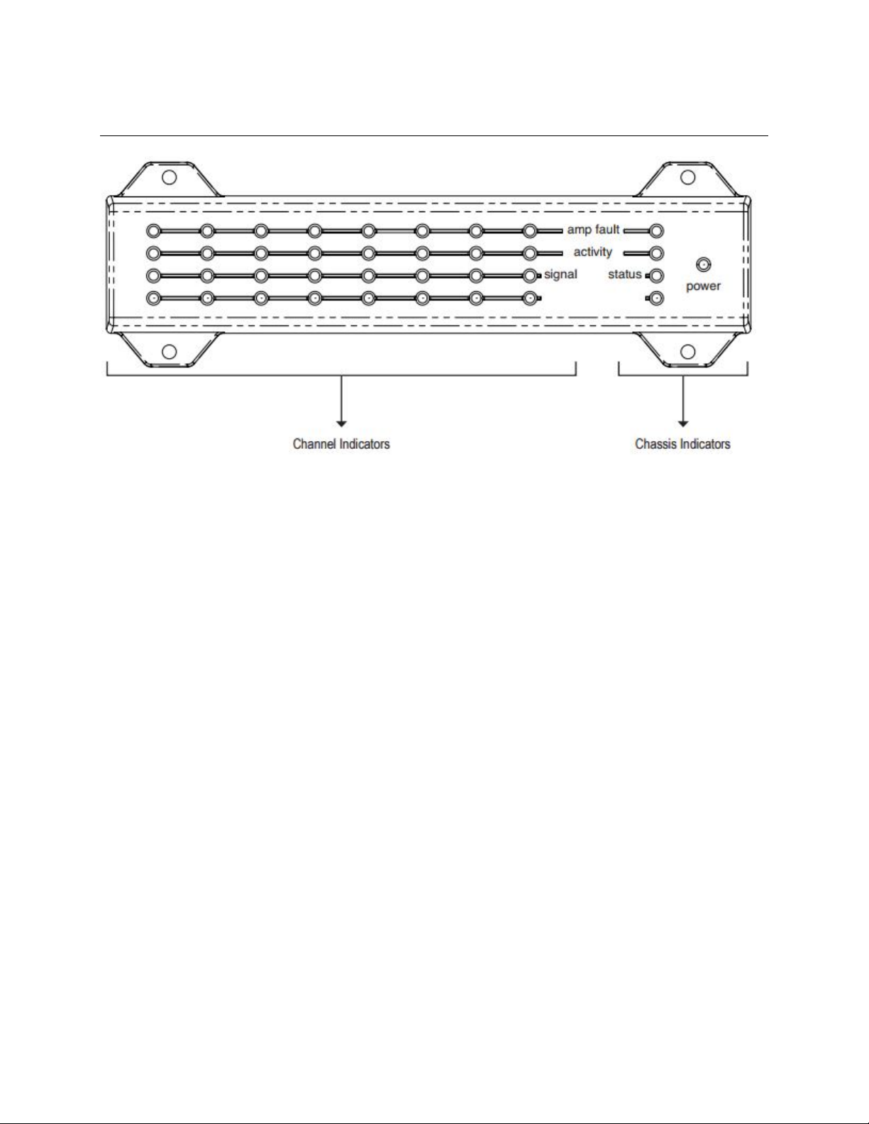
VA-8600 Front
System Indicators
The LED indicators on the front panel provide information about the function and operational status of the
VA-8600 and VA-8600c chassis and any installed AM-600 or AM-600c amplifier modules. Columns one
through eight correspond to the eight amplifier module slots. The remaining LEDs correspond to the VA8600 and VA-8600c chassis.
Amplifier Chassis Indicators
These indicators relate to the entire amplifier unit (chassis).
Power
AC power is a green LED indicator. This will illuminate when a Mains supply is applied to the unit.
Amp Fault
An amber LED illuminates when a chassis fault has occurred.
• Flashing Amber LED - Warning -the amplifier chassis or an AM-600 module is not operating
within normal limits. If the condition causing the warning is not corrected, chassis failure may
occur.
• Solid Amber LED – Fault - the amplifier chassis or AM-600 has failed - audio may have stopped.
Activity
Activity indicates the configuration status of the Amplifier.
• LED off - the unit is not active.
• Green LED - the unit is configured and passing audio.
• Amber LED - the unit is configured as a redundant device in a failover configuration.
• Red LED - Configuration load failure.
Status
Status indicates the health of the amplifier hardware.
• Green LED - indicates that the unit powered up normally.
• Amber Flashing LED - shown briefly during the power-up self test.
• Red LED - the unit experienced a problem during the power-on self test.
Amp Channel Indicators
These indicators relate to each amplifier channel.
Page 5
Amp Fault
Red
Amber
Green
Dark
Signal above clip
Signal above nominal but
below clip threshold
>
< 0dBFS
Signal above minimum but below
nominal threshold
>
<
Signal below
minim
<
An amber LED illuminates when a chassis or amplifier module fault has occurred.
• Flashing Amber LED - Warning -the amplifier chassis or an AM-600 module is not operating
within normal limits. If the condition causing the warning is not corrected, chassis failure may
occur.
• Solid Amber LED – Fault - the amplifier chassis or AM-600 has failed - audio may have stopped.
Activity
The Activity LED will illuminate when the channel is configured.
• Green LED - configured and actively passing audio.
• Amber LED - channel is acting as a standby channel for failover applications.
Signal
threshold
> 0dBFS
-3dBFS
-50dBFS
-3dBFS
um threshold
-50dBFS
Page 6
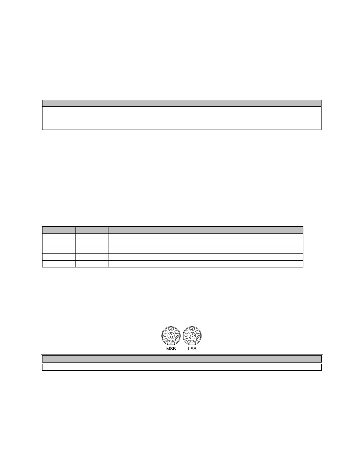
VA-8600 Rear
CAUTION
Do not remove or defeat the ground prong on the power cord, as this will constitute a shock hazard. Equipment should be
for all service requirements.
Left LED
Right LED
Description
None
None
No Data Connectivity or CobraNet activity
None
Green
Link established
Flashing yellow
Green
Link established and CobraNet activity detected; The unit is acting as a CobraNet Performer
Flashing yellow
Flashing green
Link established and CobraNet activity detected; The unit is acting as a CobraNet Conductor
Flashing yellow
None
CobraNet fault. Check cabling and configuration for errors
NOTE
Changes made to the Device ID while connected to the network require a power cycle of the device in order to take effect.
AC Power Socket
Provides for connection of the appropriate power cord. A switch selects the operating voltage for the
power supply, 110-120V or 220-240V at 50/60Hz. Make sure to disconnect the power of the unit before
toggling the switch.
connected to a mains socket outlet with a protective earthing connection. This plug is the main disconnecting device and should
remain readily operable. There are no user interchangeable parts. Please contact Biamp Technical Support or your local distributor
Network Connections
The amplifier is a CobraNet device. A Primary and Secondary CobraNet connection is provided for this.
All CobraNet routing and bundle assignments are processed by the Vocia devices locally. Vocia makes
dynamic use of available bundles in CobraNet. A 100Base-T Ethernet switch (not repeater hub) is
required when networking multiple units. CobraNet utilizes standard CAT5, CAT5e, CAT6, or CAT7
cabling, which has a specified maximum length of 328 feet (100 meters). Additional Ethernet switches, or
switches which provide fiber-optic interface, can be used to extend the physical distance between units
within a network. Please note that CobraNet limits network extensions to seven hops (one-way
transmissions) within a network. The CobraNet network connection is configured with the primary
connector on the left and the secondary (redundant) connector on the right. The primary and secondary
CobraNet ports are provided to facilitate connection redundancy. Each connector provides two LEDs that
indicate Ethernet link and network activity.
Device ID switches
The rotary ID switches give the unit a unique Device ID. The switches are in hexadecimal format. All units
of the same device type must have a unique Device ID to function properly within a Vocia Paging World.
The Factory Default Device ID is 01. A Device ID of 00 is invalid and cannot be used.
To assign a Device ID of hex 07, leave the MSB switch on 0 and turn the LSB switch to 7. Device ID
switches should be set using a 0.1 inch (2.5mm) to 0.12 inch (3.0mm) flat blade screwdriver.
Network Module (NM-1)
NM-1 is the Network Module that is included with VA-8600 and VA-8600c. This module provides
connectivity for control and audio via the dual CobraNet interface and logic ports for the device failover
functionality. The RJ45 connector labeled "Ethernet" is not used at this time.
Page 7
Reset Button
CAUTION
All Speaker wiring connections should be made by qualified personnel and with the amplifier power removed. The 100V output
requires Class 3 wiring. Please refer to a qualified electrician or other qualified person according to local codes.
Reset button, when held down for 5 seconds, performs a chassis restart. The Status indicator will flash
yellow during restart and will turn solid green once the process is complete.
Logic I/O
The Logic I/O connector on the NM-1 facilitates redundant device failover only. It is not a general-purpose
contact closure interface. See the Amplifier-to-Amplifier Failover section below.
Page Active Relays
An optional Page Active Relay card can be added to the VA-8600(c) to provide a contact closure audio
activity is detected on a particular output channel. Please see the PARM-1 datasheet or manual for
operating instructions. Note that if the Page Active Relay module is being used 3:1 or 7:1 failover will not
be available as it requires the failover module to be placed in slot 9 (as well). Channel to Channel failover
does not require a module and therefore can be used in conjunction with the PARM-1 card.
AM-600/AM-600c
A VA-8600 or VA-8600c chassis can be populated with up to eight AM-600 or AM-600c cards. The
AM600c reports a fault if it detects a short to ground on a speaker line, where this short would
compromise the capability of the amplifier to deliver emergency messages
Amplifier Output Connections
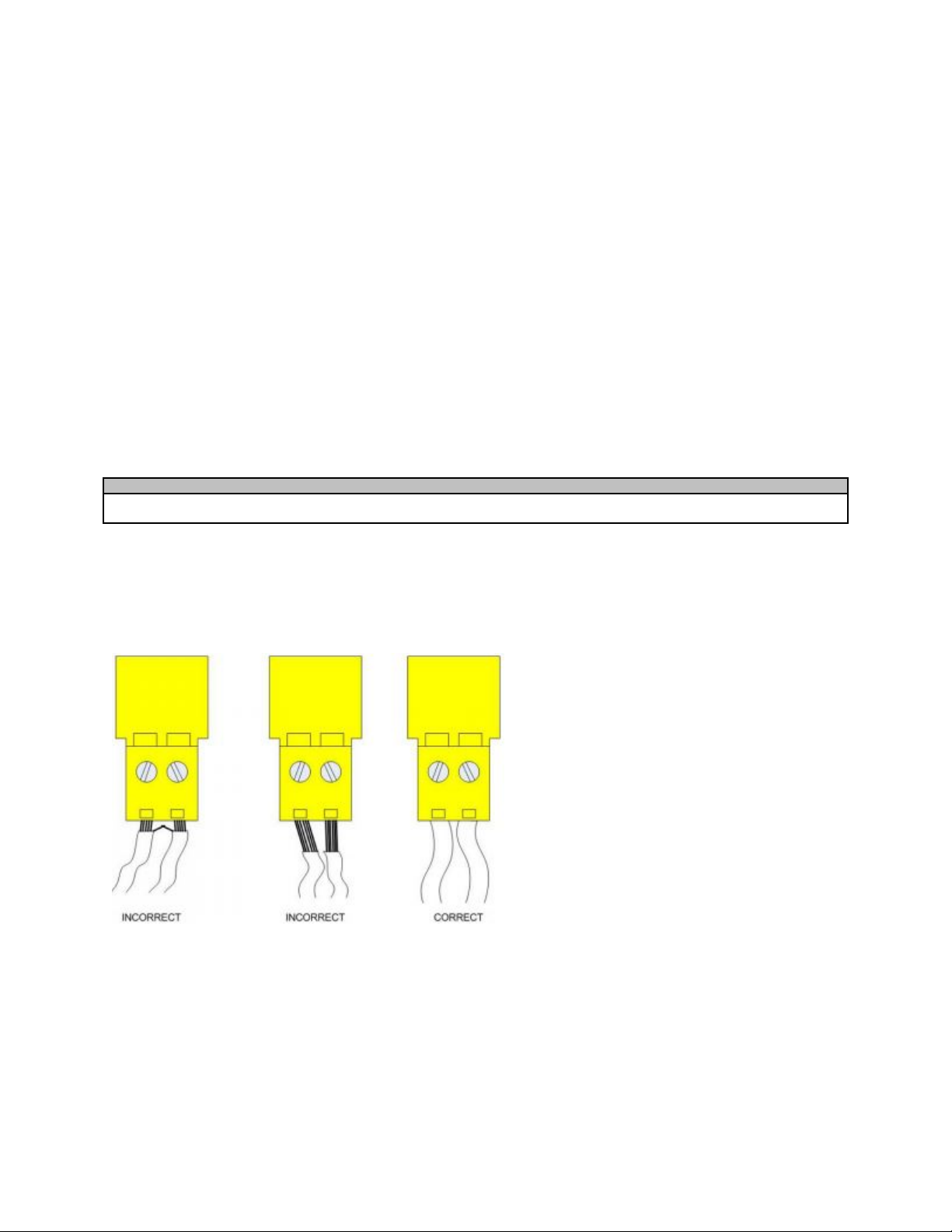
Use the yellow plug-in barrier strip connectors to connect loudspeaker level outputs. If stranded speaker
wire is used, be sure to incorporate all strands into the connector, as stray strands can short to the
adjacent terminal or chassis. Do not leave excessive bare wire outside the terminals, as this can lead to
shorts.
Please note: The VA-8600 and VA-8600c are powerful amplifiers and can damage loudspeakers. Please
treat the VA-8600 and VA-8600c outputs as you would AC mains power outlets. Always check the
loudspeaker’s continuous and peak power capabilities and match the amplifier settings accordingly.
Page 8
VA-8600 Fault Detection
Amplifier-to-Amplifier Failover
Vocia supports one-to-one automatic amplifier failover in case of fault. Failover is triggered by one of the
following conditions:
• Chassis fault
• Channel fault
• Loss of power
• Loss of CobraNet link
• Loss of Logic I/O
Only faults (e.g., heat sink fault and channel failure fault) trigger the failover mechanism. Warnings
indicate abnormal system conditions that do not immediately impair audio and do not trigger the failover
mechanism.
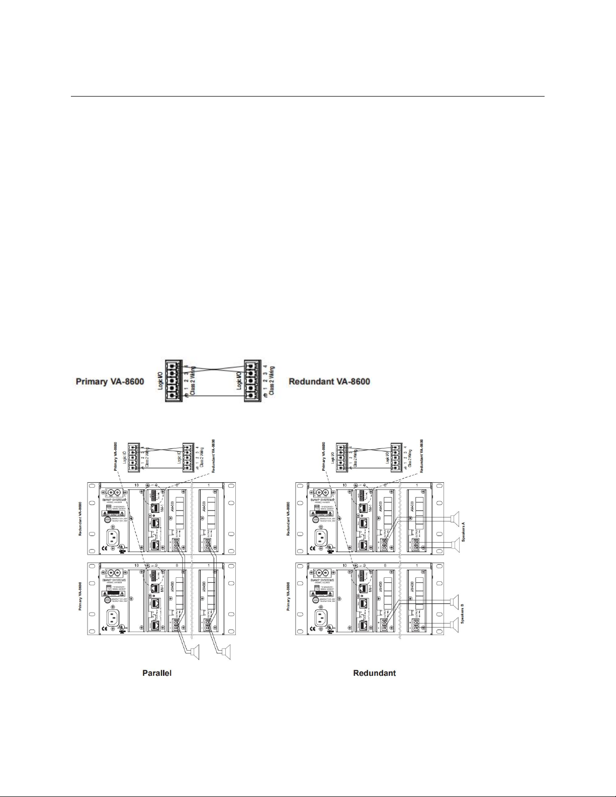
The redundant amplifier must have the same configuration as the primary amplifier (i.e., amplifier module
count, watts per module, load configuration). A wire failover link cable must be connected between the
primary and the redundant amplifier as shown below. Connect ground to ground and logic 4 of the
primary amplifier to logic 3 of the redundant amplifier; connect logic 3 of the primary amplifier to logic 4 of
the redundant amplifier. Leave logic 1 and 2 disconnected. The redundant amplifier can be wired in
parallel to the existing speaker line or it can be connected to a redundant speaker line (see figure below).
Relays isolate the output terminals on the secondary VA-8600 or VA-8600c unit. Relays are normally
open. When a configuration is received, relays close on the primary VA-8600 or VA-8600c and remain
open on the redundant VA-8600 or VA-8600c. On failover, the relay position is switched.
After replacing the faulty amplifier, a power cycle is required to recover from failover. The primary device
will resume control after the fail condition is cleared and the unit is re-powered.
Page 9
Channel-to-Channel Failover
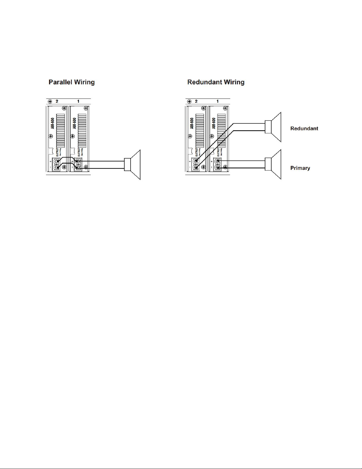
In addition to entire amplifier failover, Vocia supports channel-to-channel failover, which is triggered by
one of the following conditions: • Heat Sink fault • Short Circuit fault • Channel Failure fault The wire
failover link cable is not required when wiring channel-to-channel failover.
The redundant channel can be wired in parallel to the existing speaker line (shown above) or connected
to a redundant speaker line. The primary amplifier module will resume control after the fault condition is
cleared and the unit is re-powered.
Page 10
VA-8600 Specification
TOTAL CONFIGURED
(WATTS)
AM600 CARDS
PINK NOISE
BTU/HR
PINK NOISE
BTU/HR
FULL
SINE WAVE
BTU/HR
No cards
0
0.3
106
NA
NA
NA
NA
NA
NA
100
1
0.6
218
0.7
227
0.9
244
1.6
406
200
1
0.6
218
0.8
239
1.3
271
2.7
491
300
1
0.6
218
1.0
251
1.6
300
3.8
590
400
1
0.6
218
1.1
263
2.0
333
4.9
668
500
1
0.6
218
1.3
278
2.4
356
6.1
788
600
1
0.6
218
1.4
297
2.8
413
7.3
910
700
2
0.8
331
1.8
418
3.4
551
8.9
1211
800
2
0.8
331
2.0
430
3.8
577
10.0
1296
900
2
0.8
331
2.1
442
4.2
607
11.1
1395
1,000
2
0.8
331
2.2
454
4.5
640
12.2
1473
1,100
2
0.8
331
2.4
469
4.9
663
13.4
1592
1,200
2
0.8
331
2.5
488
5.3
720
14.5
1715
1,300
3
1.1
443
3.0
609
6.0
858
16.2
2015
1,400
3
1.1
443
3.1
621
6.3
884
17.3
2101
1,500
3
1.1
443
3.2
633
6.7
914
18.4
2199
1,600
3
1.1
443
3.4
644
7.1
947
19.5
2278
1,700
3
1.1
443
3.5
660
7.4
970
20.6
2397
1,800
3
1.1
443
3.7
679
7.8
1026
21.8
2520
1,900
4
1.4
556
4.1
800
8.5
1165
23.4*
2820
2,000
4
1.4
556
4.2
812
8.8
1191
24.5*
2905
2,100
4
1.4
556
4.4
824
9.2
1221
25.7*
3004
2,200
4
1.4
556
4.5
835
9.6
1254
26.7*
3083
2,300
4
1.4
556
4.7
851
9.9
1276
27.9*
3202
2,400
4
1.4
556
4.8
870
10.4
1333
29.1*
3325
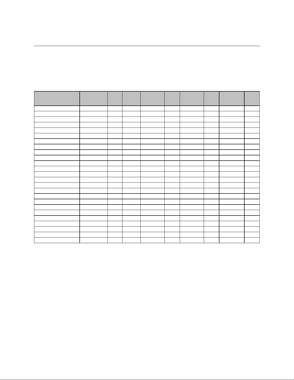
VA-8600/VA-8600c 115 VAC Current Draw and Heat Output
To determine the AC line current draw and heat output for the configuration, start by finding the total
power for the configured Vocia chassis. Then refer to the column that describes the type of audio levels
the amplifier will be producing. If your configuration uses more amplifier modules than the number shown,
add 0.3 amps and 112 BTU/hr for each additional module in the chassis.
OUTPUT POWER
NUMBER OF
IDLE
AMPS
IDLE
BTU/HR
1/8 POWER
1/3 POWER
POWER
Notes:
For 230 VAC, multiply the current by 0.5.
For each additional module above 4, add 0.3 A to the current draw and 112 BTU/hr to the heat output.
* Burst mode only. Protective thermal limiting will reduce long-term AC current and continuous power
output.
 Loading...