

Page 1

Elite
Installation Manual
DOC8003, Rev. B
March, 2003
Installation
Manual
www.vantagemobility.com
1-800-348-VANS
1
Page 2
Elite
Installation Manual
DOC8003, Rev. B
March, 2003
Introduction
Thank You!
Vantage Mobility International wishes to express our sincere appreciation on your purchase of the
Elite lift. Our engineering and manufacturing team have designed and assembled the finest lift of
this type in the mobility industry.
This manual includes important safety precautions, installation instructions, and maintenance
information and should be reviewed in its entirety prior to installing and operating the Elite lift.
WARNING!
READ MANUAL BEFORE INSTALLING LIFT.
! !
Warranty Registration Instructions and Coverage
FAILURE TO DO SO MAY RESULT IN SERIOUS
BODILY INJURY AND/OR PROPERTY DAMAGE.
VMI Limited Warranty
Inside Mounted Lift Products
Effective 3/17/2003
Vantage Mobility International (VMI) of Phoenix, Arizona warrants its lift products against defects in material and
workmanship as follows:
Parts: VMI will replace defective parts for thirty six (36) months from the warranty commencement date.
Labor: VMI will reimburse for repair labor for thirty (30) days from the warranty commencement date at a rate of
not more that $45.00 per labor hour. VMI will, under no circumstances, reimburse for the time it take to install the
lift. VMI will honor this warranty providing the products are installed by an authorized VMI dealer, maintained
properly, and operated properly. This warranty is limited to the original purchaser and does not cover the defects in
the motor vehicle in which the lift is installed, defects in the products caused by a defect in any part of the motor
vehicle, or damage to the motor vehicle caused by operating the lift. The lift warranty commences on the date of
the original installation or use, whichever comes first, providing the Warranty Card is fully and correctly filled out
and returned to: Vantage Mobility International, 5202 S. 28th Place, Phoenix, AZ 85040, within 10 working days
from the date of installation. This warranty does not cover normal maintenance, service or periodic adjustments
necessary due to normal use or wear. Vantage Mobility International will under no circumstances accept liability for
loss of use of the product or vehicle in which it is installed or loss of time. This warranty will become null and void if
the product has been damaged due to accident, misuse or neglect or if the product has been altered in any
respect. Replacement parts will be shipped via UPS ground service.
Record of Revisions
CommentsRevision DateRevision
March, 2003Rev. B
Manual reformatted, document control implemented.
2
Page 3

Elite
Installation Manual
DOC8003, Rev. B
March, 2003
Prior to Installation
1. Before Beginning the Installation
Immediately upon receiving the Elite lift, inspect the unit for any damage that may have occurred during
shipping. Notify the carrier immediately of any claims of damage.
Included in the documentation package is a yellow warranty card which is to be filled out completely by
the installing organization and returned to VMI within 10 days of the installation of the lift.
NOTE: THE WARRANTY CARD MUST BE PROCESSED IN
ORDER TO ACTIVATE THE WARRANTY.
The lift serial number can be found on the silver sticker on the winch of the Elite lift. Record this number
and all other requested information on the card, detach it from the larger portion of the warranty record
and mail to VMI postage paid.
2. Return Authorization Procedure
a. In the event of a failure or product replacement, contact VMI Technical Support at 1-800-348-8267
for a return authorization. You may fax a claim to 602-304-3277.
b. Once approved, VMI Technical Support will mail a return authorization tag to the dealership.
c. All components should be carefully packaged in the original package if possible for shipment.
d. The carrier will pick up the unit and return it to VMI for assessment.
3. Packing List and Required Tools for Installation
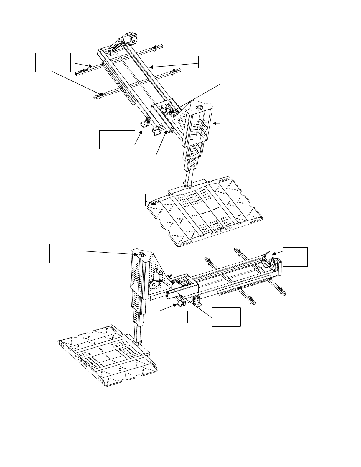
Refer to the illustrations on Page 4 for a breakdown of the components that comprise the Elite lift. Also
included is a list of the tools required to properly install the Elite lift.
3
Page 4
Elite
Installation Manual
DOC8003, Rev. B
March, 2003
Dog Bone
Bars
Elite
Packing List:
Qty. Description
(1) Winch Unit
Brackets
(1) Track
(1) Platform
(1) Manual Override Handle
(2) Dog Bone Bars
(2) Front Brackets
(1) Nylon Retaining Strap
(1) Installation Wiring
Harness
(1) Installation Hardware Kit
(1) Owner’s Manual
(1) Warranty Card
Track
Manual
Override
Bolt
Winch
Front
Trolley
Platform
Top
Roller
Ramp
Lifting
Motor
Drive
Motor
Installation
Tool List:
Ratchet
3/4” Deep Socket
9/16” Socket
1/2” Socket
3/4” Box Wrench
9/16” Box Wrench
1/2” Box Wrench
Wire Crimper
Phillips Screwdriver
Drill w/ 1/2” Bit
5/16” Box Wrench
7/16” Deep Socket
4
Page 5

Elite
Installation Manual
DOC8003, Rev. B
March, 2003
1.0 General Installation and Operation Warnings
WARNING!
READ MANUAL BEFORE INSTALLING THE LIFT.
! !
FAILURE TO DO SO MAY RESULT IN SERIOUS
BODILY INJURY AND/OR PROPERTY DAMAGE.
1. Read and understand the operating and manual override instructions prior to use of the Elite lift.
2. Read and understand all safety precautions prior to installing or operating the Elite lift.
3. Discontinue use of the lift if it appears to be functioning abnormally and contact VMI technical
support immediately for assistance.
4. Fully engage the vehicle parking brake prior to installing or operating the Elite lift.
5. Vehicle door, tailgate or hatch must be positively secured in the open position before the Elite lift is
operated.
6. NEVER use the Elite lift to load human beings, or objects other than powerchairs or scooters into
the vehicle.
7. Operators and bystanders must keep clear of all moving parts during the entire operating cycle of
the Elite lift. Keep hands and clothing away from all moving parts during operation of the lift.
8. Keep the operating instructions and manual override wrench accessible and in the vehicle with the
lift.
9. When installing the Elite Lift, check for any obstructions such as the fuel tank, fuel lines, electrical
circuitry, or exhaust components prior to drilling holes in the vehicle or routing the electrical
connections.
10. The Elite lift must be installed and serviced by an authorized VMI dealer.
11. Disconnect the negative terminal of the vehicle’s battery before beginning the installation.
12. Ensure that the Elite will clear the rear bumper, hatch and interior vehicle surfaces prior to installing
the lift.
13. Replace any missing or worn decals.
2.0 Principle of Operation
The Elite lift is powered by two 12 volt, DC electrical motors wired to the electrical system of the vehicle.
The UP and DOWN functions operate when one of the motors turns a drive screw which propels the
platform along a steel track. At the end of travel, a magnetic limit switch activates a second motor which
raises and lowers the platform assembly to the ground. The lift is activated via a switch unit at the end
of an electrical cord, or via remote control and will complete a half cycle by depressing and holding the
appropriate switch.
5
Page 6
Elite
Installation Manual
DOC8003, Rev. B
March, 2003
3.0 Installation Procedure
3.1 Check Scooter/Powerchair for Proper Fit
The Elite lift has a maximum lifting capacity of 300 lbs. Ensure the scooter/powerchair does not exceed
the maximum weight capacity of the Elite lift. Ensure the scooter or powerchair will fit within the 27.5” x 44”
envelope of the platform. Prior to beginning installation, place the gray platform on the ground and position
the scooter or powerchair on the platform to ensure that the platform and the scooter/powerchair will match.
Check the height of the scooter/powerchair, add 4.25” to that height, and compare the result with the interior
headroom of the cargo area, and the door opening. It will probably be necessary to fold down the seat back
on the scooter/powerchair, and the handle bars on the scooter, if possible. If the platform, headroom and
door opening will accommodate the scooter/powerchair, proceed with the installation to step 3.2.
3.2 Verify Adequate Space in Vehicle for Installation
Follow these steps to ensure that the Elite lift will accommodate the vehicle in which you intend to perform
the installation and also the scooter/powerchair that you intend to use.
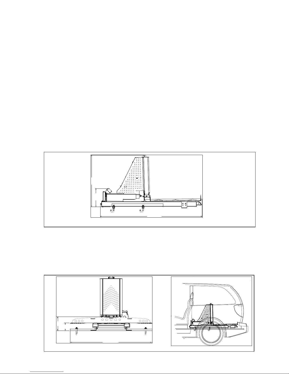
3.2.1 Length. Remove any rear seating from the rear 1/3 of the vehicle cargo area.
Place the track assembly inside the vehicle with the electric motor towards the front of the vehicle.
The Elite lift will require approximately 56” from the rear load line of the hatch. At the rear of the track
assembly, the motor extends 10” above the inside floor surface of the vehicle.
30”
10”
56”
Figure 3-1. Verifying Adequate Length in Cargo Area
3.2.2 Width. Ensure that the platform will fit inside the width of the cargo area.
The platform is 44” wide and requires 1” of clearance on each side for proper operation.
3.2.3 Height. Ensure that the motor will clear the rear seat.
The Elite measures approximately 29” from the top of the roller to the interior floor. The lowest point on
the surface of the platform rises 4.25” from the surface of the floor.
7.5”
4.25”
Figure 3-2. Verifying Adequate Width and Height in Cargo Area
44”
6
Page 7
Elite
Installation Manual
DOC8003, Rev. B
March, 2003
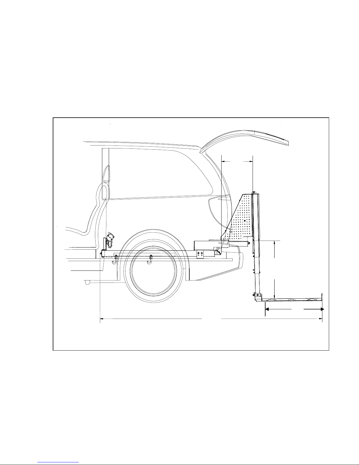
3.2.4 Extension. The Elite lift will extend 28” from the interior floor surface of the vehicle to the
ground. Measure the total height to ensure that the Elite lift will reach the ground when fully-extended.
3.2.5 Bumper Clearance. The Elite lift will extend 15” from the rear load line inside the cargo
area to its maximum outward travel. Ensure that the unit will clear the bumper, trailer hitch or any
other obstructions along the centerline of the vehicle.
15”
100”
Figure 3-3. Verifying Proper Extension and Bumper Clearance
29.5”
27.5”
7
Page 8
Elite
Installation Manual
DOC8003, Rev. B
March, 2003
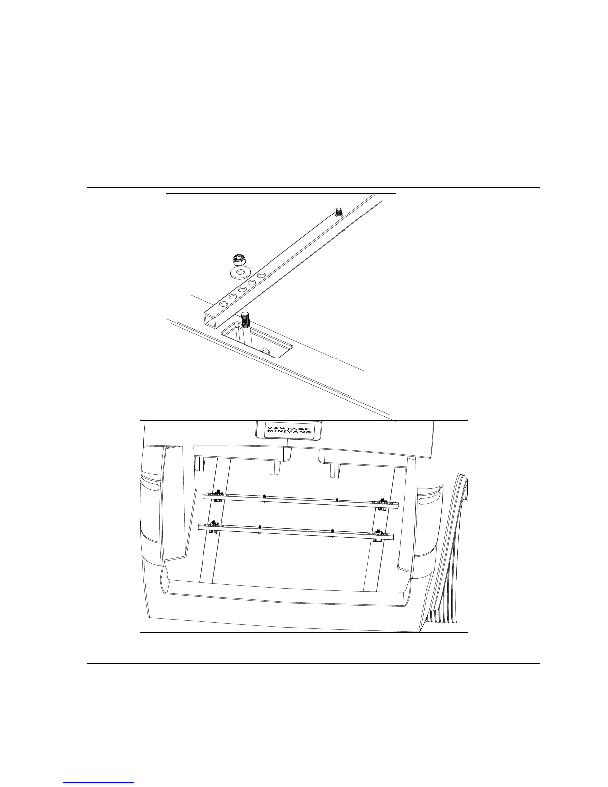
3.3 Install the Dog Bone Bars
Disconnect the negative terminal of the vehicle’s power system from the negative pole of the battery.
Place the two dog bone installation bars over two sets of dog bones in the rear of the vehicle as
illustrated below. Center the bars directly over the dog bones and insert the J-bolts such that they hook
around the dog bones and the threaded portion of the J-bolts run through the holes on the bars. Using
the 1/2” washers and the 1/2”-13 Nylock nuts provided, start the nuts on the J-bolts, but do not tighten at
this time. In the event that the vehicle in which you are installing the Elite does not have dog bones
available, bolt the dog bone bars directly to the floor of the vehicle.
NOTE: Before proceeding to step 3.4, the rear of the vehicle should look as shown above.
Figure 3-4. Dog Bone Bar Installation
8
Page 9
Elite
Installation Manual
DOC8003, Rev. B
March, 2003
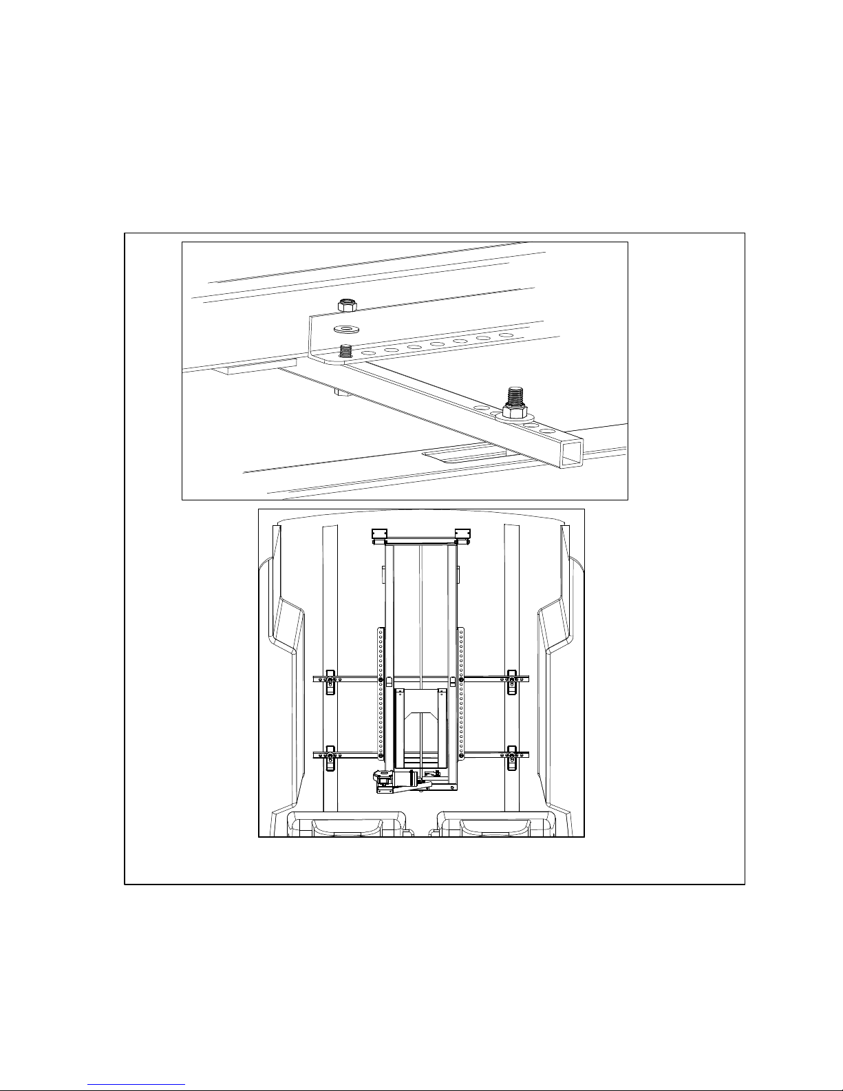
3.4 Attach the Track to the Dog Bone Bars
Lay the track in the vehicle such that the back edge is 1” behind the load line. It may be necessary to
cut into the plastic threshold if the base unit is too long for the cargo area of the vehicle. Pass the 3/8”
bolts on the dog bone bars through the appropriate holes in the base unit tracks. Using a ratchet, four
3/8” washers and four 3/8” Nylock nuts, tighten the base unit to the dog bone bars.
NOTE: Ensure the track is centered in the cargo space.
Figure 3-5. Attaching Track to Dog Bone Bars
9
Page 10
Elite
Installation Manual
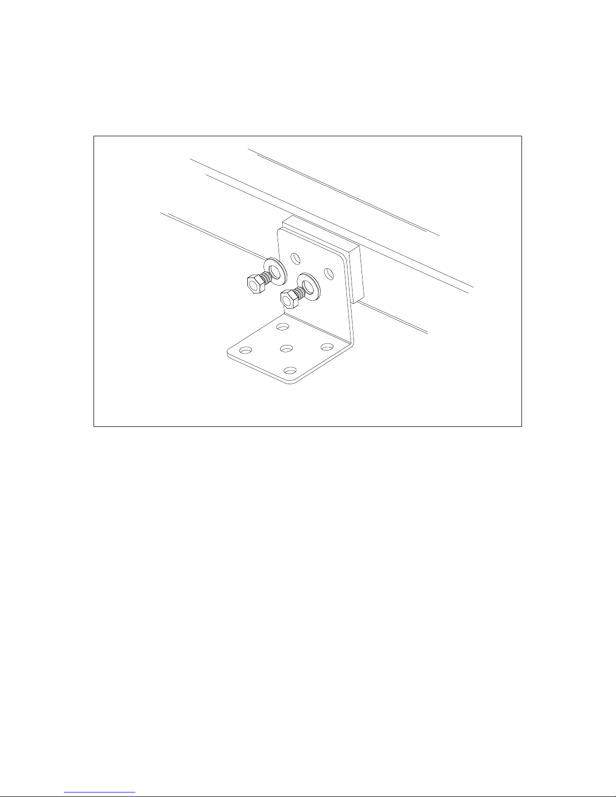
3.5 Install the Front Angle Brackets
Place the two angle brackets on the mounts at the front of the track and tighten completely.
DOC8003, Rev. B
March, 2003
Figure 3-6. Front Angle Bracket Installation
3.6 Secure the Track
Tighten the 1/2” Nylock nuts on the J-bolts completely, ensuring that the hook portion of the J-bolt
securely catches the dog bones in the floor of the vehicle.
3.7 Install the Electrical Harness
Run the wiring installation harness from the rear of the base unit to the engine compartment near the
battery. This can be accomplished by running the red and black wires through a hole in the floor,
under the car to the battery, or under the carpet to the front of the vehicle and through a hole in the
firewall. Route the harness away from sharp or hot objects such as fender panels or the exhaust
system. Avoid moving parts such as drive axles or engine components. Install the fuse as close to
the battery as possible using the two screws provided in the installation wiring kit. Wire the battery
side of the fuse directly to the battery and then connect the auxiliary side of the fuse to the Elite
harness. Connect the negative terminal directly to the negative pole of the battery. Reconnect the
negative terminal of the vehicle to the negative pole on the battery.
Connect the power and ground wires on the electrical harness to the installation wiring kit leads from
the battery. There are two additional wires on the Elite harness intended to allow the Elite remotes to
operate a rear power hatch if the vehicle is so equipped. Contact VMI Technical Support for
assistance with this feature.
10
Page 11
Elite
Installation Manual
DOC8003, Rev. B
March, 2003
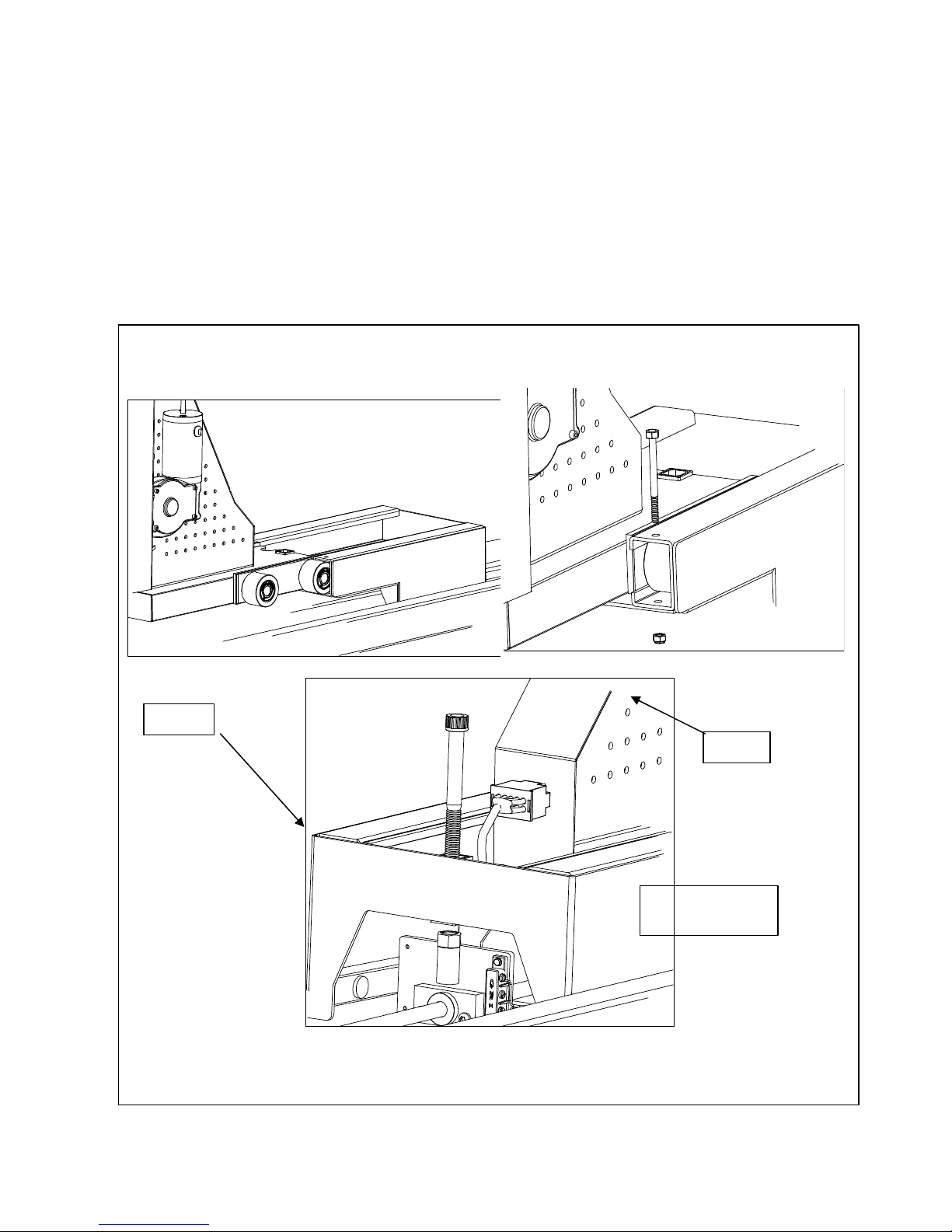
3.8 Install the Winch Assembly
Ensure the four wheels are attached to the protruding axles and align them with the track. Slide the
winch head unit onto the trolley assembly completely. Using the two 3” bolts and nuts provided, close
out the end of the trolley track to trap the winch head unit as shown below.
3.9 Connect the Winch Assembly to the Drive Screw
Using the provided bolt, align the winch head unit with the drive screw assembly and insert the bolt and
tighten finger tight (See Figure 3-7).
Trolley
Winch
Route wiring
in front of trolley!
Figure 3-7. Winch Assembly Installation and Attachment to Drive Screw
11
Page 12
Elite
Installation Manual
3.10 Connect the Electrical System
Plug in the two harness plugs to the winch unit. Plug in the optional pendant switch to the winch unit.
CAUTION!!
!
ENSURE THAT THE HARNESSES TRAVEL FROM THE DRIVE SCREW ASSEMBLY IN FRONT
OF THE TROLLEY TO THE PLUG ON THE WINCH! DO NOT ROUTE THE HARNESSES BEHIND
THE REAR OF THE TROLLEY UNIT OR THE HARNESS WILL BE DESTROYED WHEN THE
UNIT REACHES THE END OF ITS TRAVEL!
3.11 Platform Installation
Using the remote control transmitter, or the pendant switch, run the unit “out” until it reaches
completely outside the vehicle and begins to extend the lifting mechanism down to the ground.
CAUTION!!
!
ONCE THE WINCH REACHES THE LIMIT OF ITS TRAVEL DOWN, STOP THE UNIT BY
RELEASING THE SWITCH! IF THE UNIT IS RUN CONTINUALLY ONCE THE PLATFORM HAS
REACHED THE GROUND, THE EXCESS TETHER WILL UNSPOOL AND COULD BECOME
ENTANGLED WITH THE INTERNAL MECHANISMS. STOP PRESSING THE DOWN BUTTON AS
SOON AS THE UNIT COMES TO REST ON THE GROUND!
DOC8003, Rev. B
March, 2003
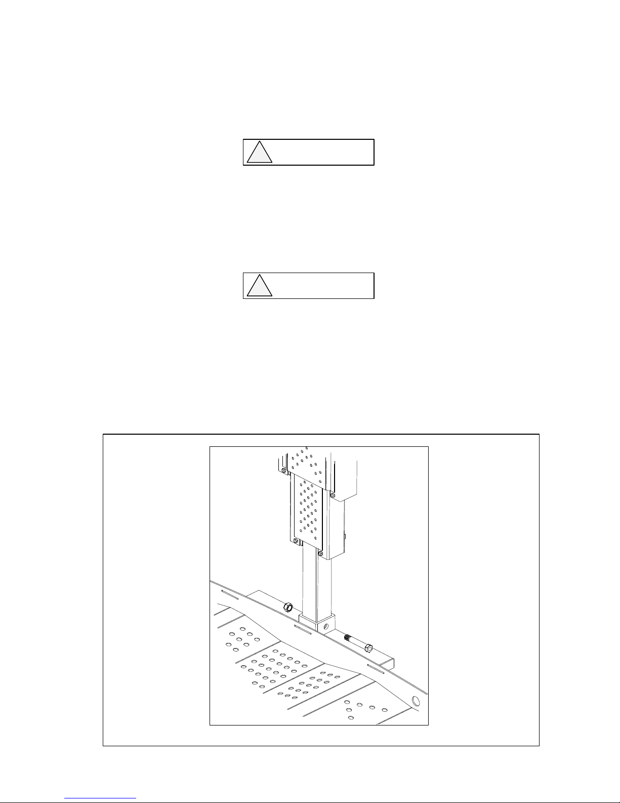
Position the welded platform assembly under the unit as shown and align the mast with the
gooseneck assembly. Place the 1/2”-13 bolt through the four holes as shown in Figure 3-8 below.
Tighten the 1/2”-13 Nylock nut completely.
Figure 3-8. Platform Installation
12
Page 13
Elite
Installation Manual
DOC8003, Rev. B
March, 2003
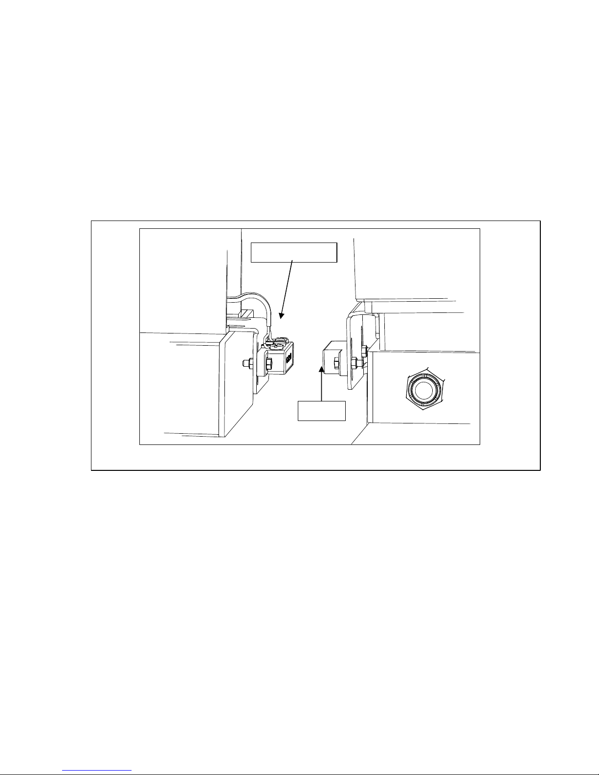
3.12 Adjust the Magnetic Limit Switches
Using the transmitter or pendant switch, raise the unit and observe its clearance with the outside bumper.
As the unit reaches the limit of its upward travel, the magnetic switch should shut down the “up” function,
and activate the “in” function. If the unit has not traveled upward sufficiently to clear the threshold of the
vehicle, adjust the magnetic limit switch upwards to trigger the electrical changeover later in the cycle.
This will allow the unit to go up farther before it attempts to travel inwards. Do not adjust the limit switch
so high that the platform never touches the rollers as it travels in. The roller assembly was designed to
bear some of the platform weight during the inward cycle. Do not allow the platform to “hover” over the
track for the duration of its inward travel. The Elite lift was designed with a 3 degree angle to the winch.
This feature was included to compensate for the compression of the vehicle’s suspension system under a
heavy load.
Magnetic Switch
Magnet
Figure 3-9. Magnetic Limit Switch Adjustment
3.13 Check for Door Clearance
Allow the unit to travel in completely ensuring that the platform clears the passenger and driver interior
walls of the cargo space. Once the unit travels inside completely, it will stop when the magnetic switch is
activated. Close the rear hatch carefully to ensure the platform clears the closed rear door. Take care to
observe the scooter/powerchair as it begins to travel into the vehicle to ensure that the headrests clear
the roofline of the cargo space. Before closing the hatch, ensure that the armrests (if present) will clear
the hatch when closed.
3.14 Install the Retaining Strap
Open the hatch and return the unit to the outside extended position. Place the customer scooter or
powerchair onto the platform. Center the scooter/powerchair onto the platform and install the nylon
retaining strap. The strap can be installed in one of three locations on the platform as appropriate for the
chair. The strap is only intended to limit unwanted motion of the mobility device during transport.
A magnet is included in the kit to hold the retaining strap out of the way during loading or unloading.
Attach the magnet to the face of the Elite winch head for this purpose.
13
Page 14
Elite
Installation Manual
3.15 Install the Magnetic Lockout System
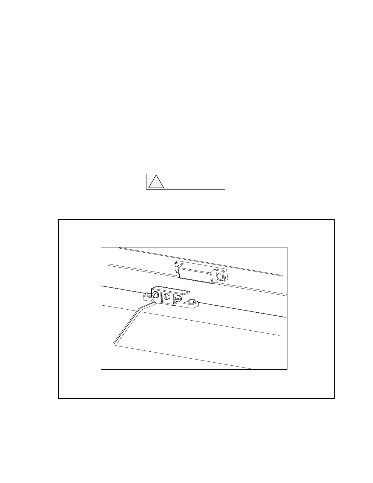
Secure the brown magnetic switch extending from the front of the track to the threshold or floor using the
two self-tapping screws provided. Attach the magnet half of the switch to the hatch using the two selftapping screws provided (See Figure 3-10). The switch and magnet should be positioned such that they
come within 1/4” of each other when the hatch is closed. When the magnet activates the magnetic switch,
the remote control circuit will be deactivated in order to prevent the unit from being operated with the
remote control when the hatch is closed. The pendant controls will still operate with the hatch shut, and
care must be taken to ensure that the unit is not operated with a closed hatch.
NOTE: DO NOT UTILIZE THE EMERGENCY RELEASE SYSTEM UNLESS THE
VEHICLE IS PARKED ON LEVEL GROUND! THE ELITE WINCH AND PLATFORM WILL
ROLL FREELY ONCE THE BOLT IS REMOVED. INJURY OR PROPERTY DAMAGE
COULD OCCUR. MOVE THE VEHICLE TO LEVEL GROUND BEFORE ATTEMPTING
THIS PROCEDURE.
CAUTION!!
!
OPERATING THE UNIT WITH THE HATCH CLOSED MAY DAMAGE THE INTERIOR SURFACE
OF THE HATCH AND DESTROY THE SCREW DRIVE MECHANISM ON THE ELITE LIFT.
DOC8003, Rev. B
March, 2003
Figure 3-10. Installation of Magnetic Lockout System
14
Page 15

Elite
Installation Manual
DOC8003, Rev. B
March, 2003
3.16 Program the Remote Transmitters
If the Elite lift you are installing has remote transmitters, it may be necessary to program them.
During the inspection process at the factory, both transmitters were programmed and were
functional. Due to changes in the power supply, it is possible that the transmitters may have lost
their program. To program the remote control units, the magnetic lockout switch MUST have been
installed on the rear door or hatch. If it has not been installed, you must place the magnet against
the magnet switch for the duration of the programming process. To program, perform the following:
1. Close the rear door or hatchback (or hold magnet against the switch).
2. Open the vehicle hood and disconnect the vehicle negative battery terminal.
3. With the transmitters at hand, reconnect the negative battery terminal. Within 5 seconds of
reconnecting the negative terminal, push the “IN” button on the first transmitter, then
the “IN” button on the second transmitter.
4. Open the rear door or hatchback (or remove the magnet from the switch). Test each transmitter
for proper operation of all four channels.
5. If programming was unsuccessful, repeat the process, making sure the magnet switch was
properly engaged. If programming was successful, tighten the negative battery terminal and
attach the remote transmitters to the keychain. Call VMI technical support if you require
assistance with the programming process.
15
Page 16

Elite
Installation Manual
DOC8003, Rev. B
March, 2003
4.0 Perform Customer Orientation and Operation Overview
Upon completion of the Elite Lift installation, perform an operational overview and safety review
with the customer. Refer to the Elite Owner’s Manual and Operating Instructions for detailed
information to review with the customer.
5.0 Maintenance Schedule and Procedure
Your Elite lift must be maintained periodically to ensure years of reliable service. Failure to properly
maintain your lift may result in unnecessary damage to the unit and could void the warranty. Follow the
procedures described below:
To Be Performed With Every Use:
1. Before activating the unit, ensure the tracks are clear of debris and foreign objects.
2. Ensure there are no obstacles on the ground below the unit.
3. Ensure that the unit has sufficient clearance to operate freely without touching or scraping against any
portion of the vehicle interior or exterior.
4. Monitor the condition of the blue strap to ensure that there is no fraying or splitting. Any indication that
the strap is frayed should be brought to the attention of your authorized VMI dealer immediately.
Failure to do so may result in injury or loss of proper function.
5. Ensure that the scooter/powerchair will not touch the roof or inside of the vehicle as the unit travels
in or out.
6. Keep the unit out of rain or excessive exposure to water. In the event of exposure to water, towel dry
the unit to prevent rust or corrosion.
7. Ensure the vehicle is parked on level ground before operating the Elite lift. Do not try to operate the
lift with the vehicle parked on sloped ground!
To Be Performed Monthly:
1. Clean and inspect the interior of the track system to ensure that it is clear of debris or foreign objects.
Inspect the condition of the wheels for wear.
2. Ensure the screw is lightly lubricated with graphite powder and is free of debris and dirt.
3. Check the security of all electrical connections. Ensure there is no chafed or exposed electrical wire.
4. Ensure the magnetic limit switch under the winch head is properly adjusted and the screws are
tight.
5. Check the condition of the black retaining strap for fraying or wear. Replace immediately if signs of
excessive wear are present.
6. Lightly lubricate the chain assembly at the rear of the unit with a spray lubricant such as WD-40 to
prevent unwanted noise or wear.
7. Check the tightness of all exposed nuts and bolts to ensure that they are present and secure.
To Be Performed Annually:
Return your Elite Lift to your authorized VMI dealer for annual maintenance and evaluation.
16
Page 17
Elite
Installation Manual
DOC8003, Rev. B
March, 2003
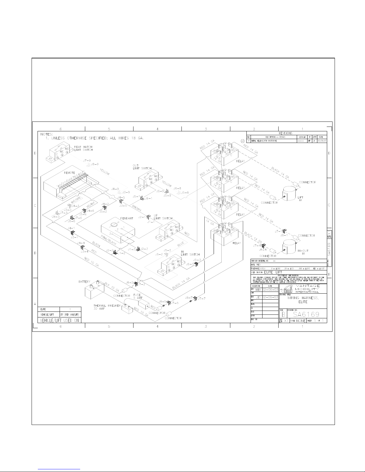
Elite Wiring Diagram
17
 Loading...