

Page 1
VS1063a Prog. Guide
VS1063a Programmer’s Guide
MP3/OGG/AAC/WMA/FLAC/
G.711/G.722 AUDIO CODEC CIRCUIT
Key Features
• Encoders:
MP3; Ogg Vorbis; PCM; IMA ADPCM;
G.711 (µ-law, A-law); G.722 ADPCM
• Decoders:
MP3 (MPEG 1 & 2 audio layer III (CBR
+VBR +ABR));
MP2 (layer II) (optional);
MPEG4 / 2 AAC-LC(+PNS),
HE-AAC v2 (Level 3) (SBR + PS);
Ogg Vorbis; FLAC;
WMA 4.0/4.1/7/8/9 all profiles (5-384 kbps);
WAV (PCM, IMA ADPCM, G.711 µ-law/Alaw, G.722 ADPCM)
• Full Duplex Codecs:
PCM; G.711 (µ-law, A-law); G.722 ADPCM
• Streaming support
• Upto 96 KiB RAM for user code and data
• Unique ID for user code protection
• Quiet power-on and power-off
• I2S interface for external DAC
• Serial control and data interfaces
• Can be used either as a slave co-processor
or as a standalone processor
• UART for debugging purposes
• New functions may be added with soft-
ware and upto 12 GPIO pins
Description
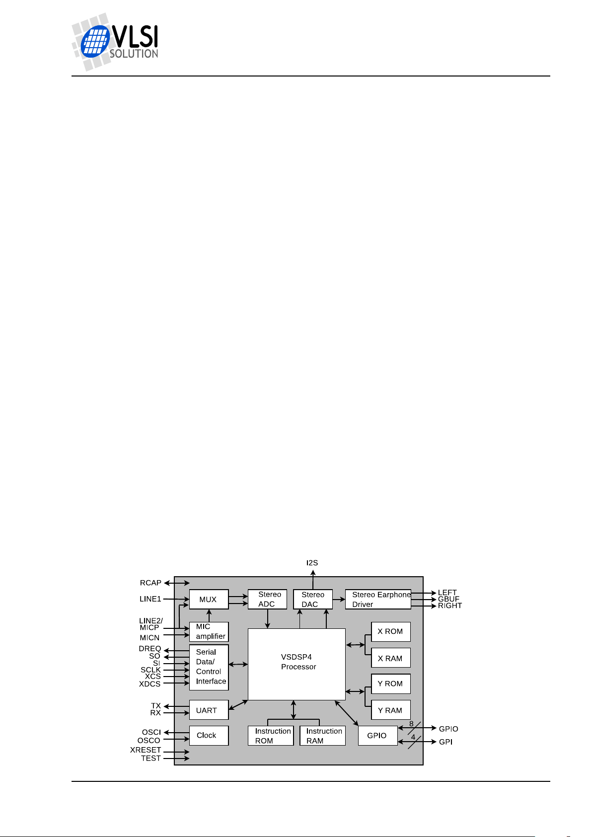
VS1063a is an easy-to-use, versatile encoder,
decoder and codec for a multitude of audio
formats.
VS1063a contains a high-performance, proprietary low-power DSP core VS_DSP4, ROM
memories, 16 KiB instruction RAM and upto
80 KiB data RAM for user applications running simultaneously with any built-in decoder,
serial control and input data interfaces, upto
12 general purpose I/O pins, a UART, as well
as a high-quality variable-sample-rate stereo
DAC and a stereo ADC, followed by an earphone amplifier and a common voltage buffer.
VS1063a can act both as an “MP3 decoder
IC” or “MP3 encoder IC” slave in a system
with a microcontroller, or as a stand-alone circuit that boots from external SPI memory.
Applications
• MP3-recording audio player
• Streaming server and client
• Wireless audio transfer
• Standalone player and recorder
• Internet phones
Version: 0.40, 2011-09-02 1
PRELIMINARY
Page 2
VS1063a Prog. Guide
Additional Features
• EarSpeaker Spatial Processing
• Bass & treble controls
• Alternatively a 5-channel equalizer
• AD Mixer allows monitoring A/D con-
verter input while listening to stream
• PCM Mixer allows inserting a sidestream
while listening to main stream
• Adjustable Speed Shifter
• Operates with a single 12..13 MHz or
24..26 MHz clock
• Internal PLL clock multiplier
• Low-power operation
• High-quality on-chip stereo DAC with no
phase error between channels
• Zero-cross detection for smooth volume
change
• Stereo earphone driver capable of driving a 30 Ω load
• Separate voltages for analog, digital, I/O
• Lead-free RoHS-compliant package
Further Description
Operating Modes
VS1063a operates in one of two host modes:
as a slave co-processor or as a standalone
processor.
When used as a slave co-processor VS1063a
can operate in three different operation modes:
decoder, encoder or codec mode. In decoder
mode VS1063a receives its input bitstream
through a serial input bus. The input stream
is decoded and passed through an 18-bit digital volume control to an oversampling sigmadelta DAC. Decoding is controlled via a serial
control bus. In addition to the basic decoding, it is possible to add application specific
features, like DSP effects, to the user RAM
memory, or even to load user applications.
In encoder mode VS1063a can reads audio
from its analog inputs, optionally compresses
the data, which can then be read by the host
processor. In codec mode VS1063a offers a
full-duplex audio interface.
When used as a standalone processor the
VS1063a can boot either from SPI EEPROM
or FLASH memory. Alternatively code and
data can be provided by a host controller.
VS1063a is a pin-compatible alternative for
VLSI Solution’s VS1053. It has all the functionality of VS1053 (except MP1 and MIDI
decoding) and many new features, particularly MP3 and Ogg Vorbis recording.
Also full-duplex codec functions for phone applications have been added to VS1063a.
A factory-programmable unique chip ID provides a basis for digital rights management or
unit identification features.
User Code
Users can write their own user interface or
signal processing code for the VS1063a using VSIDE (VLSI Solution’s Integrated Development Environment).
As a default, there are 16 KiB of free code
RAM and about 4 KiB of free data RAM for
user applications. Depending on the application, the data RAM can be expanded to the
full 80 KiB that is available in VS1063a.
Version: 0.40, 2011-09-02 2
PRELIMINARY
Page 3
VS1063a Prog. Guide
CONTENTS
Contents
VS1063 1
Table of Contents 3
List of Figures 4
1 Introduction 5
2 Disclaimer 5
3 Definitions 6
4 Interfacing with VS1063a Using a Microcontroller 7
4.1 The SCI (SPI) Bus . . . . . . . . . . . . . . . . . . . . . . . . . . . . . . . . . . 7
4.1.1 Example SCI Read / Write Implementation . . . . . . . . . . . . . . . 8
4.1.2 SCI Bus Access Example . . . . . . . . . . . . . . . . . . . . . . . . 9
4.2 The SDI (SPI) Bus . . . . . . . . . . . . . . . . . . . . . . . . . . . . . . . . . . 9
5 Writing Plugins 10
5.1 Plugin Memory Maps . . . . . . . . . . . . . . . . . . . . . . . . . . . . . . . . . 10
5.1.1 Plugin Instruction Memory Map (32-bit words) . . . . . . . . . . . . . 10
5.1.2 Plugin X Data Memory Map (16-bit words) . . . . . . . . . . . . . . . 10
5.1.3 Plugin Y Data Memory Map (16-bit words) . . . . . . . . . . . . . . . 11
5.2 Implementing a Plugin to the Decoder Audio Path . . . . . . . . . . . . . . . . . 11
5.2.1 Loading and Activating the Plugin . . . . . . . . . . . . . . . . . . . . 12
5.2.2 Audio Path Plugin Call Conventions . . . . . . . . . . . . . . . . . . . 12
5.2.3 Simple Example Audio Path Plugin . . . . . . . . . . . . . . . . . . . 13
5.2.4 Disabling the Audio Path Plugin . . . . . . . . . . . . . . . . . . . . . 14
5.2.5 VSIDE and Audio Path Plugins . . . . . . . . . . . . . . . . . . . . . 14
5.3 Idle Hook Plugin . . . . . . . . . . . . . . . . . . . . . . . . . . . . . . . . . . . . 15
5.4 Interrupt-Driven Plugin . . . . . . . . . . . . . . . . . . . . . . . . . . . . . . . . 15
6 Writing User Applications that Take Full Control over VS1063a 16
6.1 Application Memory Maps . . . . . . . . . . . . . . . . . . . . . . . . . . . . . . 16
6.1.1 Application Instruction Memory Map (32-bit words) . . . . . . . . . . 16
6.1.2 Application X Data Memory Map (16-bit words) . . . . . . . . . . . . 16
6.1.3 Application Y Data Memory Map (16-bit words) . . . . . . . . . . . . 17
6.2 Taking Control of VS1063a . . . . . . . . . . . . . . . . . . . . . . . . . . . . . . 17
6.2.1 Taking Control of Interrupts . . . . . . . . . . . . . . . . . . . . . . . 18
6.3 VSIDE and Applications . . . . . . . . . . . . . . . . . . . . . . . . . . . . . . . 18
7 Audio Format Specific Comments 19
7.1 Encoders . . . . . . . . . . . . . . . . . . . . . . . . . . . . . . . . . . . . . . . . 19
7.1.1 VLSI Solution’s Ogg Vorbis Encoder VSOVE v2.00 . . . . . . . . . . 19
7.1.2 VLSI Solution’s MP3 Encoder VSMPE v1.00 . . . . . . . . . . . . . . 19
7.2 Decoders . . . . . . . . . . . . . . . . . . . . . . . . . . . . . . . . . . . . . . . 20
7.2.1 MP3 Decoder . . . . . . . . . . . . . . . . . . . . . . . . . . . . . . . 20
8 VS1063a Load File Formats 21
8.1 VS1063a Plugin Format . . . . . . . . . . . . . . . . . . . . . . . . . . . . . . . 21
Version: 0.40, 2011-09-02 3
PRELIMINARY
Page 4
VS1063a Prog. Guide
LIST OF FIGURES
8.1.1 The .PLG Format and VSIDE . . . . . . . . . . . . . . . . . . . . . . 21
8.1.2 Example VS1063a Microcontroller Plugin Decoder . . . . . . . . . . 22
8.2 VS1063a Image Format . . . . . . . . . . . . . . . . . . . . . . . . . . . . . . . 23
8.2.1 The .IMG Format and VSIDE . . . . . . . . . . . . . . . . . . . . . . 23
8.2.2 Example VS1063a Microcontroller Boot Image Decoder . . . . . . . 24
9 Latest Document Version Changes 25
10 Contact Information 26
List of Figures
1 Decoder data flow of VS1063a with the user plugin stage highlighted . . . . . . . 11
Version: 0.40, 2011-09-02 4
PRELIMINARY
Page 5
VS1063a Prog. Guide
2 DISCLAIMER
1 Introduction
This is the VS1063a Programmer’s Guide. Its intent is to provide the reader with a sufficient
amount of information to write programs for VS1063a.
Programs can be written either as plugins which function in cooperation with VS1063a’s existing
decoder framework as shown in Chapter 5, or as applications that take over the whole system
as shown in Chapter 6.
Finally, some audio format specific comments are presented in Chapter 7.
Future versions of this document will also discuss ROM functions and VS1063a startup.
2 Disclaimer
The VS10xx Programmer’s Guide represents VLSI Solution’s best attempt at giving a VS1063a
programmer as much information as possible to help creating their own plugins and applications. Nevertheless, this guide is still highly preliminary and very much in a state of flux. It will
be made more comprehensive and accurate over time.
VLSI Solution is not responsible for any errors, omissions, or misleading statements in this
document.
This guide is the third part of a three-part entity, consisting of VS1063a Datasheet, VS1063a
Hardware Guide, and VS1063a Programmer’s Guide. To avoid repetition, it is assumed that
the reader of this guide has already familiarized himself with the other two documents.
Version: 0.40, 2011-09-02 5
PRELIMINARY
Page 6
VS1063a Prog. Guide
3 DEFINITIONS
3 Definitions
Application Standalone application that takes over the normal functionality of VS1063a. See
Chapter 6 for details.
ABR Average BitRate. Bitrate of stream may vary locally, but will stay close to a given number
when averaged over a longer time.
B Byte, 8 bits.
b Bit.
CBR Constant BitRate. Bitrate of stream will be the same for each compression block.
Ki “Kibi” = 210= 1024 (IEC 60027-2).
Mi “Mebi” = 220= 1048576 (IEC 60027-2).
Plugin A piece of software that works in tandem with the VS1063a operating system. See
Chapter 5 for details.
SCI Serial Control Interface, an SPI bus for VS1063a control.
SDI Serial Data Interface, an SPI bus for VS1063a bitstream data.
VBR Variable BitRate. Bitrate will vary depending on how difficult the source material is to
encode.
VS_DSP VLSI Solution’s DSP core.
VSIDE VLSI Solution’s Integrated Development Environment.
W Word. In VS_DSP, instruction words are 32-bit and data words are 16-bit wide.
Version: 0.40, 2011-09-02 6
PRELIMINARY
Page 7
VS1063a Prog. Guide
4 INTERFACING WITH VS1063A USING A MICROCONTROLLER
4 Interfacing with VS1063a Using a Microcontroller
This chapter explaings how to interface with the VS1063a using SCI and SDI buses, which
both are special cases of the SPI bus. This document will show how to access the buses using
microcontroller software written in C language. For details on bus signals, see the VS1063a
Datasheet Chapter “SPI Buses”.
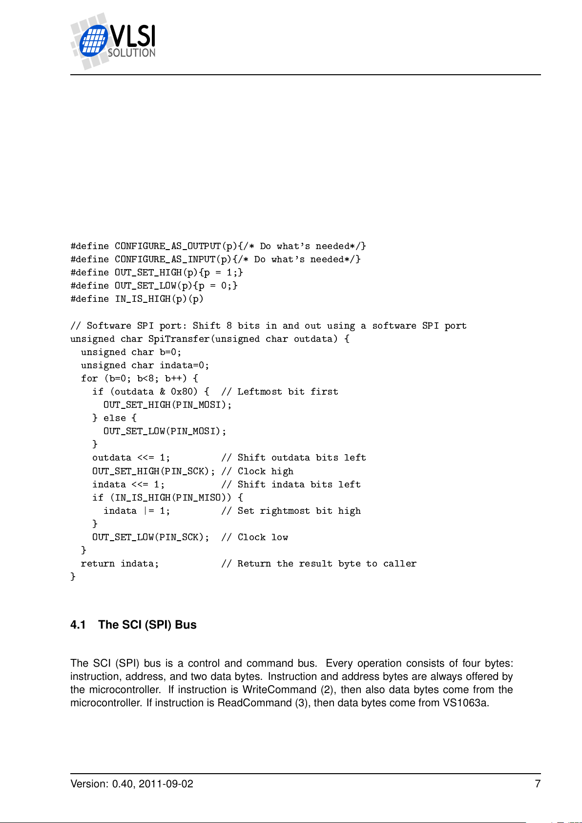
To be able to do SCI and SDI operations, let’s first define a basic one-byte SPI transfer:
#define CONFIGURE_AS_OUTPUT(p){/* Do what's needed*/}
#define CONFIGURE_AS_INPUT(p){/* Do what's needed*/}
#define OUT_SET_HIGH(p){p = 1;}
#define OUT_SET_LOW(p){p = 0;}
#define IN_IS_HIGH(p)(p)
// Software SPI port: Shift 8 bits in and out using a software SPI port
unsigned char SpiTransfer(unsigned char outdata) {
unsigned char b=0;
unsigned char indata=0;
for (b=0; b<8; b++) {
if (outdata & 0x80) { // Leftmost bit first
OUT_SET_HIGH(PIN_MOSI);
} else {
OUT_SET_LOW(PIN_MOSI);
}
outdata <<= 1; // Shift outdata bits left
OUT_SET_HIGH(PIN_SCK); // Clock high
indata <<= 1; // Shift indata bits left
if (IN_IS_HIGH(PIN_MISO)) {
indata |= 1; // Set rightmost bit high
}
OUT_SET_LOW(PIN_SCK); // Clock low
}
return indata; // Return the result byte to caller
}
4.1 The SCI (SPI) Bus
The SCI (SPI) bus is a control and command bus. Every operation consists of four bytes:
instruction, address, and two data bytes. Instruction and address bytes are always offered by
the microcontroller. If instruction is WriteCommand (2), then also data bytes come from the
microcontroller. If instruction is ReadCommand (3), then data bytes come from VS1063a.
Version: 0.40, 2011-09-02 7
PRELIMINARY
Page 8
VS1063a Prog. Guide
4 INTERFACING WITH VS1063A USING A MICROCONTROLLER
4.1.1 Example SCI Read / Write Implementation
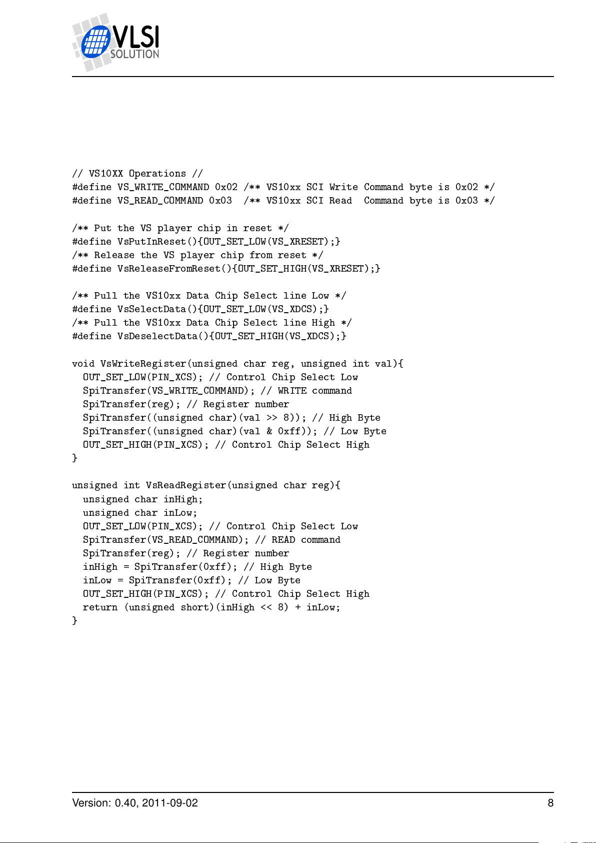
Using the SpiTransfer() function, here is how to implement register write and read functions:
// VS10XX Operations //
#define VS_WRITE_COMMAND 0x02 /** VS10xx SCI Write Command byte is 0x02 */
#define VS_READ_COMMAND 0x03 /** VS10xx SCI Read Command byte is 0x03 */
/** Put the VS player chip in reset */
#define VsPutInReset(){OUT_SET_LOW(VS_XRESET);}
/** Release the VS player chip from reset */
#define VsReleaseFromReset(){OUT_SET_HIGH(VS_XRESET);}
/** Pull the VS10xx Data Chip Select line Low */
#define VsSelectData(){OUT_SET_LOW(VS_XDCS);}
/** Pull the VS10xx Data Chip Select line High */
#define VsDeselectData(){OUT_SET_HIGH(VS_XDCS);}
void VsWriteRegister(unsigned char reg, unsigned int val){
OUT_SET_LOW(PIN_XCS); // Control Chip Select Low
SpiTransfer(VS_WRITE_COMMAND); // WRITE command
SpiTransfer(reg); // Register number
SpiTransfer((unsigned char)(val >> 8)); // High Byte
SpiTransfer((unsigned char)(val & 0xff)); // Low Byte
OUT_SET_HIGH(PIN_XCS); // Control Chip Select High
}
unsigned int VsReadRegister(unsigned char reg){
unsigned char inHigh;
unsigned char inLow;
OUT_SET_LOW(PIN_XCS); // Control Chip Select Low
SpiTransfer(VS_READ_COMMAND); // READ command
SpiTransfer(reg); // Register number
inHigh = SpiTransfer(0xff); // High Byte
inLow = SpiTransfer(0xff); // Low Byte
OUT_SET_HIGH(PIN_XCS); // Control Chip Select High
return (unsigned short)(inHigh << 8) + inLow;
}
Version: 0.40, 2011-09-02 8
PRELIMINARY
Page 9
VS1063a Prog. Guide
4 INTERFACING WITH VS1063A USING A MICROCONTROLLER
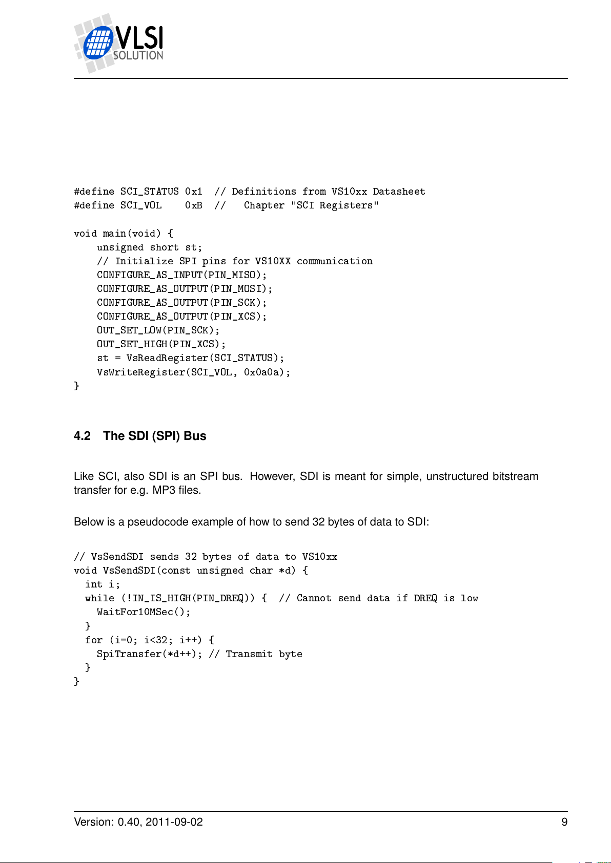
4.1.2 SCI Bus Access Example
Now that the needed support functions have been presented, below is a very simple program
that reads register SCI_STATUS, then sets SCI_VOL to 0x0a0a.
#define SCI_STATUS 0x1 // Definitions from VS10xx Datasheet
#define SCI_VOL 0xB // Chapter "SCI Registers"
void main(void) {
unsigned short st;
// Initialize SPI pins for VS10XX communication
CONFIGURE_AS_INPUT(PIN_MISO);
CONFIGURE_AS_OUTPUT(PIN_MOSI);
CONFIGURE_AS_OUTPUT(PIN_SCK);
CONFIGURE_AS_OUTPUT(PIN_XCS);
OUT_SET_LOW(PIN_SCK);
OUT_SET_HIGH(PIN_XCS);
st = VsReadRegister(SCI_STATUS);
VsWriteRegister(SCI_VOL, 0x0a0a);
}
4.2 The SDI (SPI) Bus
Like SCI, also SDI is an SPI bus. However, SDI is meant for simple, unstructured bitstream
transfer for e.g. MP3 files.
Below is a pseudocode example of how to send 32 bytes of data to SDI:
// VsSendSDI sends 32 bytes of data to VS10xx
void VsSendSDI(const unsigned char *d) {
int i;
while (!IN_IS_HIGH(PIN_DREQ)) { // Cannot send data if DREQ is low
WaitFor10MSec();
}
for (i=0; i<32; i++) {
SpiTransfer(*d++); // Transmit byte
}
}
Version: 0.40, 2011-09-02 9
PRELIMINARY
Page 10
VS1063a Prog. Guide
5 WRITING PLUGINS
5 Writing Plugins
In the context of VS1063a, a plugin is a piece of software that coexists with the audio decoder
framework of VS1063a.
Plugins may modify decoded audio data or inject new data into the audio path, use free CPU
time. They may have limited control over some interrupts.
Plugins have to take into account that the operating system is running: they cannot use any
memory areas allocated by the system and they should use as little processing power as possible.
VS1063a doesn’t have hardware resource allocation routines in its operating system, so if the
user wants to access VS1063a hardware, he has to make sure to use only such parts of it that
are not already used by the system. An example of this are interrupts: some are used by the
operating system, and some are free to use.
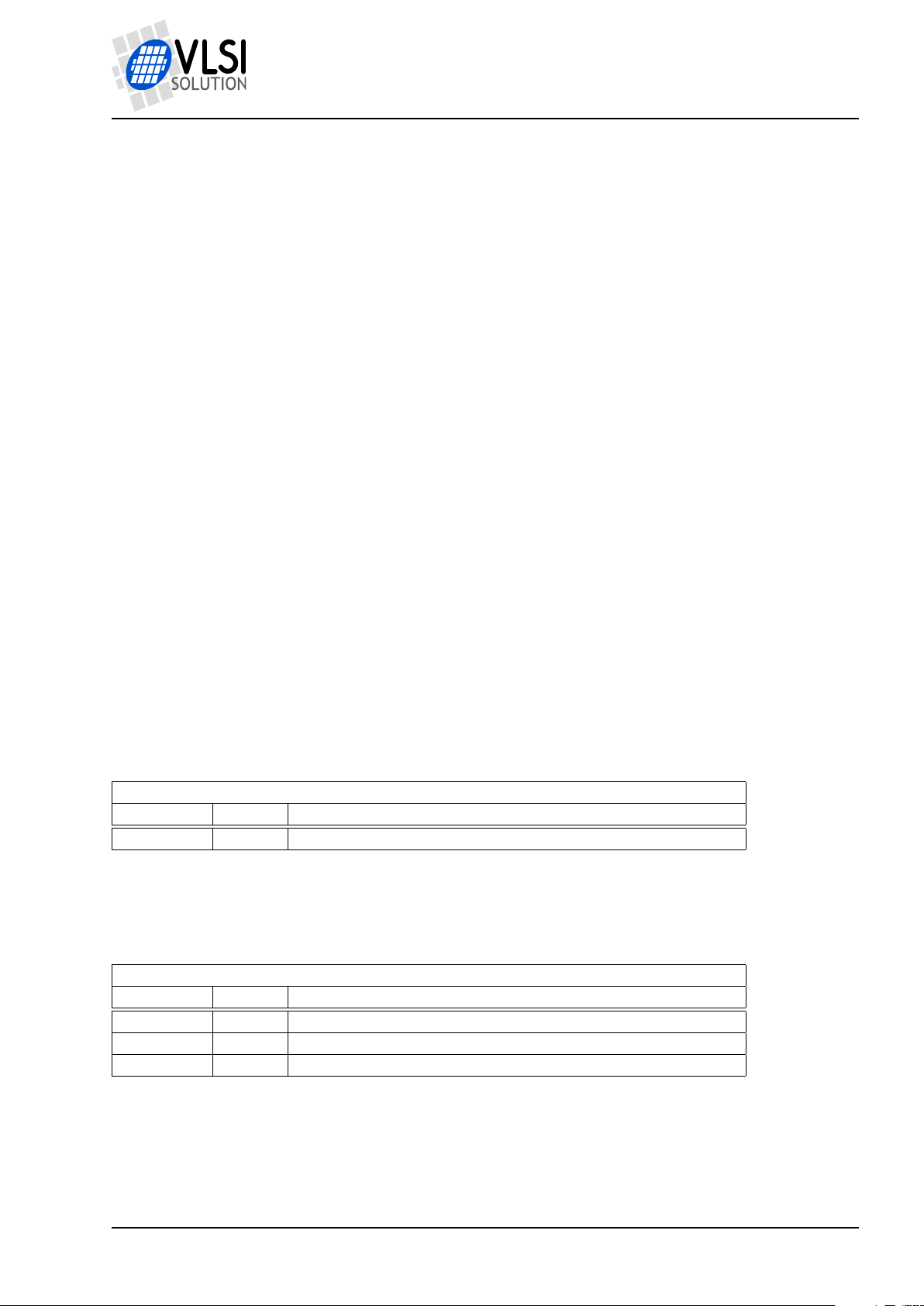
5.1 Plugin Memory Maps
This chapter presents free memory maps for plugins. All units are in words.
5.1.1 Plugin Instruction Memory Map (32-bit words)
Free instruction memory for plugins
Start Addr Length Description
0x50 0x3B0 Full I memory except jump vectors
5.1.2 Plugin X Data Memory Map (16-bit words)
Free X data memory for plugins
Start Addr Length Description
0x1800 0x80 User area
0x1C80 0x180 Extra area 1
0x1E40 0x1C0 Extra area 2
Version: 0.40, 2011-09-02 10
PRELIMINARY
Page 11
VS1063a Prog. Guide
AAC, FLAC
5−channel
Audio
PauseMono
BassUser
control
Treble Speed
EarSpeaker
equalizer
ADC
0
SCI_VOL
Bitstream
SDI bus
SCI bus
Mic/Line In
PCM audio
ST_AMPLITUDE=0SB_AMPLITUDE=0
AIADDR != 0
AIADDR=0
EQ5 Enable = 1
ST_AMPL=0 &
SB_AMPL=0 &
EarSpeakerLevel!=0 &
earSpeakerLevel=0
ST_AMPLITUDE!=0SB_AMPLITUDE != 0
adMixerGain or
pcmMixerVol
Bitstream
shifter
FIFO
enhancer
FIFO
SPEEDSHIFTER_ON=0
SPEEDSHIFTER_ON=0&
SPEEDSHIFTER_ON=1
MONO_OUTPUT=1
MONO_OUTPUT=0
PAUSE_ON
PCMMIXER_ON=1&
ADMIXER_ON=1
PCMMISER_ON=0 & ADMIXER_ON=0
ADMIXER_ON=0
To DAC
DAC
SRC
Sidestream
SDM
WAV, MP2/3,
OGG, WMA,
plugin
5.1.3 Plugin Y Data Memory Map (16-bit words)
Free Y data memory for plugins
Start Addr Length Description
0x1800 0x80 User area
0xFA14 0x3EC Extra area
5.2 Implementing a Plugin to the Decoder Audio Path
A useful case of cooperative programs is plugin user applications.
5 WRITING PLUGINS
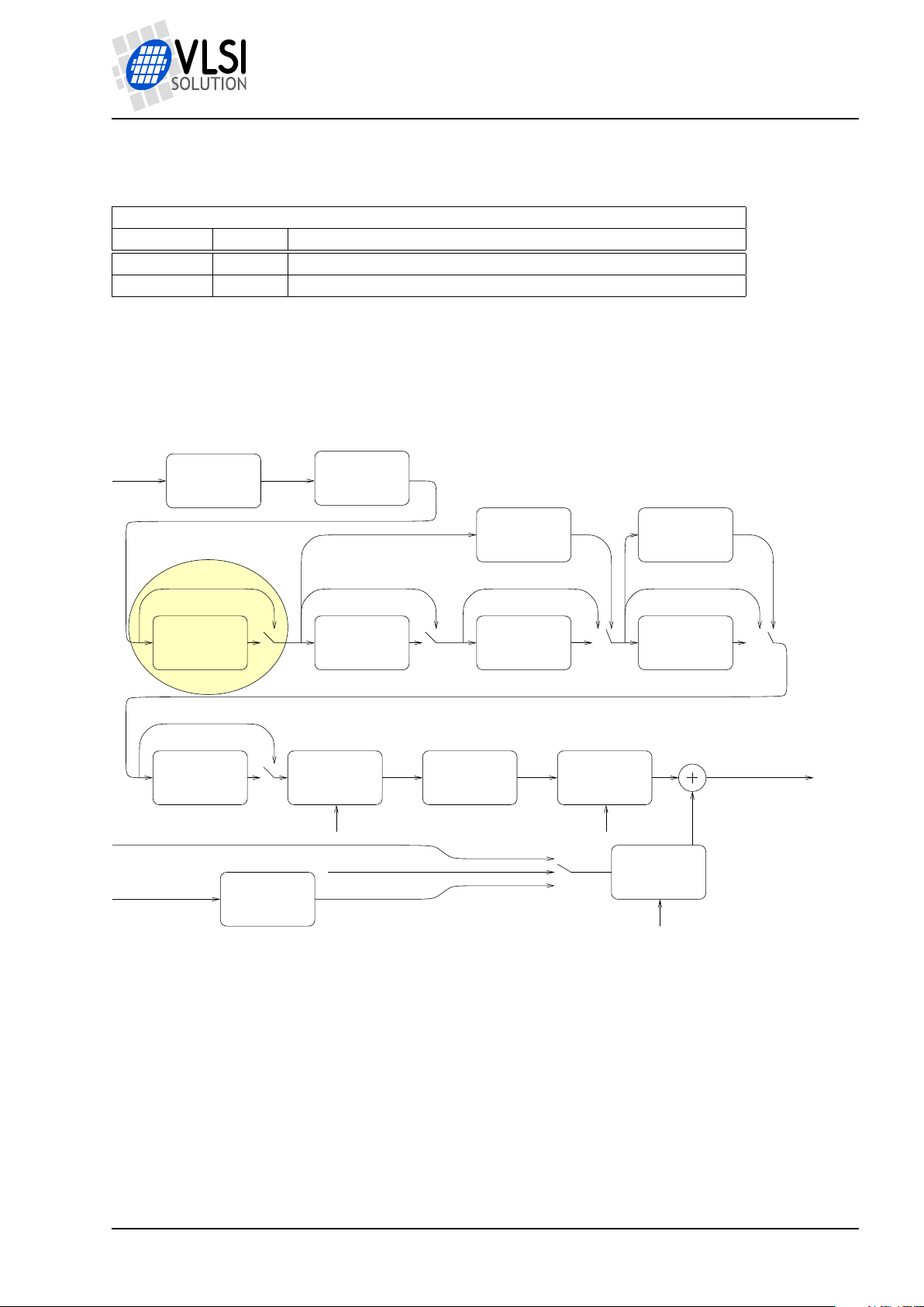
User plugins may insert themselves in the decoding signal path, as shown in Figure 1. (For
annotations for other blocks in this figure, see the VS1063a Datasheet.)
Plugins also get information on whenever SCI_AICTRL0 through SCI_AICTRL3 have been
accessed (either read from or written to), or whenever the samplerate changes.
Version: 0.40, 2011-09-02 11
Figure 1: Decoder data flow of VS1063a with the user plugin stage highlighted
PRELIMINARY
Page 12
VS1063a Prog. Guide
5 WRITING PLUGINS
5.2.1 Loading and Activating the Plugin
Loading a plugin is initiated by writing a base address to register SCI_WRAMADDR. The program and its data is then loaded by writing data to register SCI_WRAM.
The plugin is activated by writing its start address to register SCI_AIADDR. Whenever a powerdown, hardware reset or software reset has happened, the plugin needs to be reloaded and
restarted. The reason for this is that whenever VS1063a is reset, it will clear all its data areas
so the plugin will not be intact anymore.
Note: SCI_AIADDR will not be cleared when a software reset has been performed, but you still
need to reload and reactivate the plugin.
5.2.2 Audio Path Plugin Call Conventions
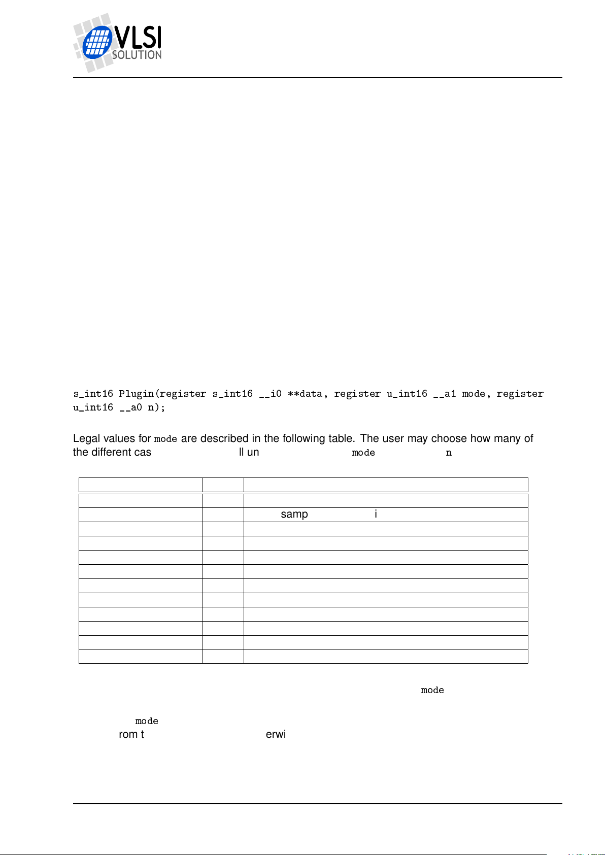
The C prototype for the user plugin is as follows:
s_int16 Plugin(register s_int16 __i0 **data, register u_int16 __a1 mode, register
u_int16 __a0 n);
Legal values for
the different cases are handled. All unhandled values for
Symbol Value Description
APPL_RESET 0 Reset all values, n is samplerate
APPL_AUDIO 1 Audio samples offered, n is number of L/R sample pairs
APPL_W0 2 SCI_AICTRL0 has been written to, n is register value
APPL_W1 3 SCI_AICTRL1 has been written to, n is register value
APPL_W2 4 SCI_AICTRL2 has been written to, n is register value
APPL_W3 5 SCI_AICTRL3 has been written to, n is register value
APPL_R0 6 SCI_AICTRL0 has been read from, n is register value
APPL_R1 7 SCI_AICTRL1 has been read from, n is register value
APPL_R2 8 SCI_AICTRL2 has been read from, n is register value
APPL_R3 9 SCI_AICTRL3 has been read from, n is register value
APPL_BITSTREAM 10 Obsolete, ignore
APPL_OUT_OF_DATA 11 Stream input buffer has starved
mode
are described in the following table. The user may choose how many of
mode
should returnn.
Note: It is guaranteed that the first call to the user plugin is always with
Note: When
different from the input samplerate. Otherwise, the user function may return 0.
Note: When returning from APPL_AUDIO, the user function should return the number of samples it created in the function. If the number of samples did not change, returning 0 is also
Version: 0.40, 2011-09-02 12
mode
= APPL_RESET, the user function should return its output samplerate if it is
mode
= APPL_RESET.
PRELIMINARY
Page 13
VS1063a Prog. Guide
5 WRITING PLUGINS
acceptable. If the number of samples did grow, samples must be written to some other location
than what is pointed to by
**d
. This new pointer must be returned in*d.
Note: If
samples in the audio output buffer. Otherwise it is 1. If the function returns non-zero, then 32
empty stereo samples will be inserted into the output audio stream. So, in a typical case it is
convenient to just returnn.
Input data is always interleaved stereo, left channel first.
Volume control is placed after any user plugins. Thus it is generally a better idea to only write
filters that attenuate some frequencies and don’t emphasize any. To compensate for the lower
volume, main volume setting may be turned higher.
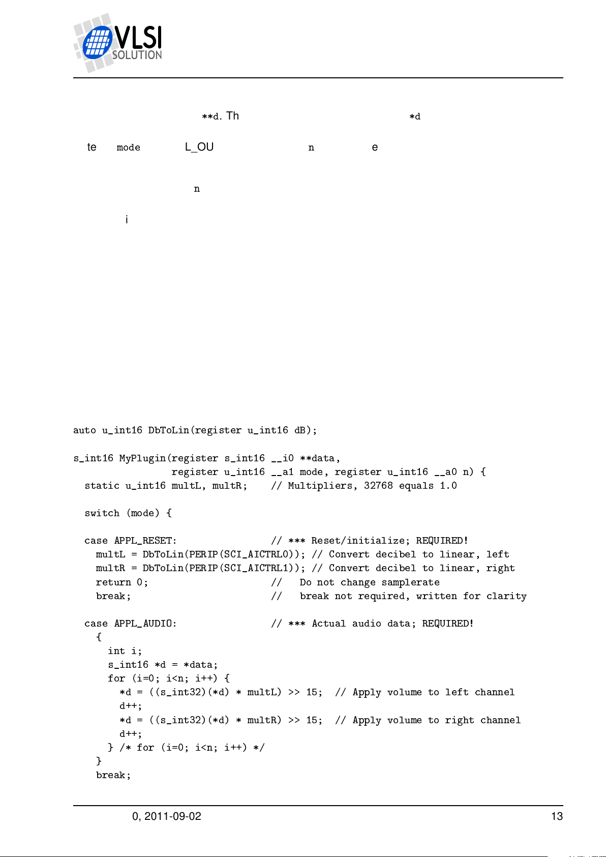
5.2.3 Simple Example Audio Path Plugin
This very simple plugin attenuates its input signal by a given number of decibels. The user
can give the number of decibels for the left channel in SCI_AICTRL0 and right channel in
SCI_AICTRL1.
auto u_int16 DbToLin(register u_int16 dB);
mode
== APPL_OUT_OF_DATA, thennis 0 if there still are still at least 64 stereo
s_int16 MyPlugin(register s_int16 __i0 **data,
register u_int16 __a1 mode, register u_int16 __a0 n) {
static u_int16 multL, multR; // Multipliers, 32768 equals 1.0
switch (mode) {
case APPL_RESET: // *** Reset/initialize; REQUIRED!
multL = DbToLin(PERIP(SCI_AICTRL0)); // Convert decibel to linear, left
multR = DbToLin(PERIP(SCI_AICTRL1)); // Convert decibel to linear, right
return 0; // Do not change samplerate
break; // break not required, written for clarity
case APPL_AUDIO: // *** Actual audio data; REQUIRED!
{
int i;
s_int16 *d = *data;
for (i=0; i<n; i++) {
*d = ((s_int32)(*d) * multL) >> 15; // Apply volume to left channel
d++;
*d = ((s_int32)(*d) * multR) >> 15; // Apply volume to right channel
d++;
} /* for (i=0; i<n; i++) */
}
break;
Version: 0.40, 2011-09-02 13
PRELIMINARY
Page 14
VS1063a Prog. Guide
5 WRITING PLUGINS
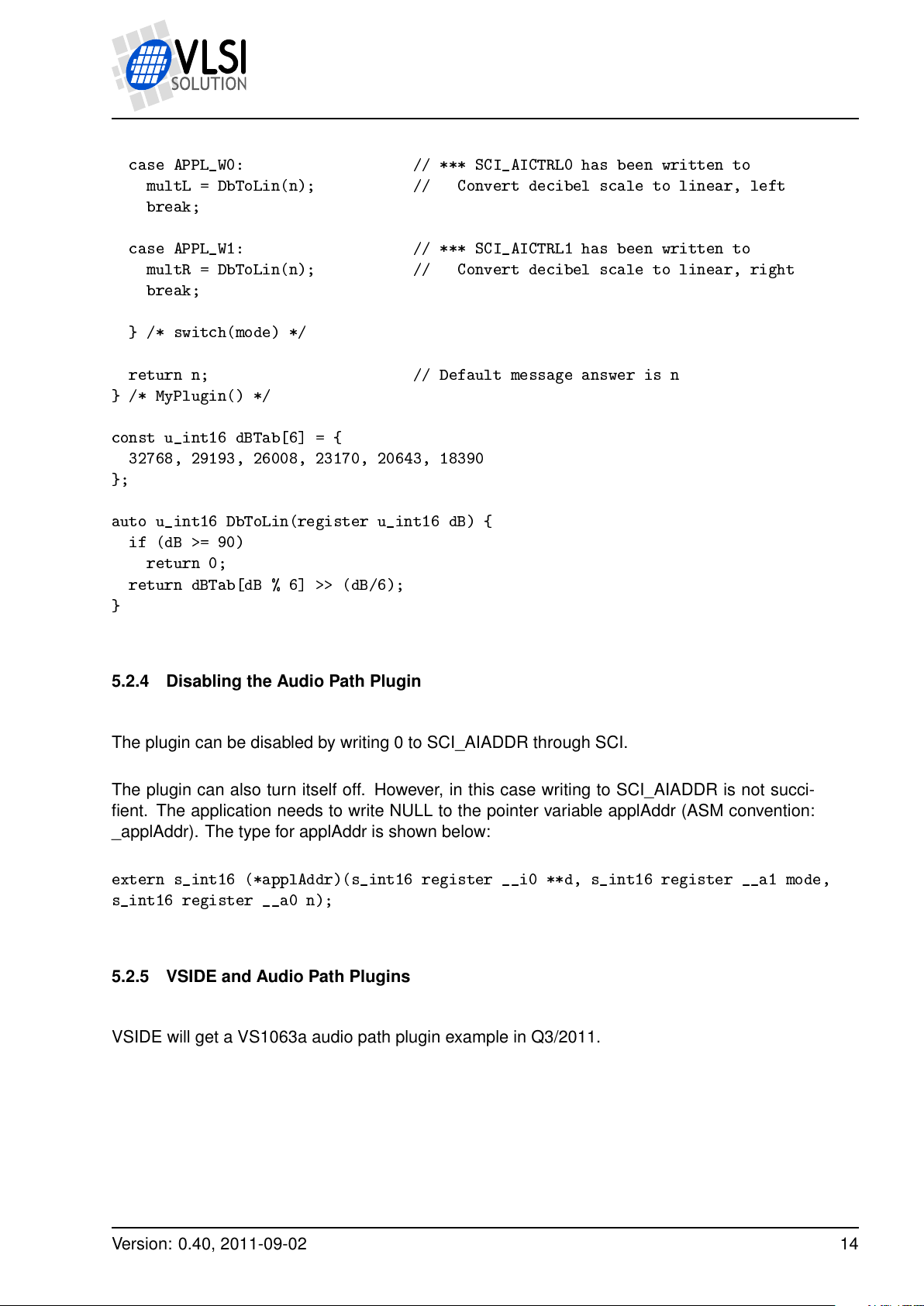
case APPL_W0: // *** SCI_AICTRL0 has been written to
multL = DbToLin(n); // Convert decibel scale to linear, left
break;
case APPL_W1: // *** SCI_AICTRL1 has been written to
multR = DbToLin(n); // Convert decibel scale to linear, right
break;
} /* switch(mode) */
return n; // Default message answer is n
} /* MyPlugin() */
const u_int16 dBTab[6] = {
32768, 29193, 26008, 23170, 20643, 18390
};
auto u_int16 DbToLin(register u_int16 dB) {
if (dB >= 90)
return 0;
return dBTab[dB % 6] >> (dB/6);
}
5.2.4 Disabling the Audio Path Plugin
The plugin can be disabled by writing 0 to SCI_AIADDR through SCI.
The plugin can also turn itself off. However, in this case writing to SCI_AIADDR is not succifient. The application needs to write NULL to the pointer variable applAddr (ASM convention:
_applAddr). The type for applAddr is shown below:
extern s_int16 (*applAddr)(s_int16 register __i0 **d, s_int16 register __a1 mode,
s_int16 register __a0 n);
5.2.5 VSIDE and Audio Path Plugins
VSIDE will get a VS1063a audio path plugin example in Q3/2011.
Version: 0.40, 2011-09-02 14
PRELIMINARY
Page 15
VS1063a Prog. Guide
5 WRITING PLUGINS
5.3 Idle Hook Plugin
Whenever VS1063a has spare time, it will first jump to an idle hook, then halt until the next
interrupt is received. The idle hook pointer is located at instruction address 0. Normally the
idle hook pointer contains a jump command to a dummy hook which does nothing. Address 1
contains a “nop” instruction (needed by VS_DSP because it almost always executes the next
instruction after a control transfer instruction).
To take control of the idle hook, first create a function with the following prototype:
void MyIdleHook(void);
Then, write the assembler command “J _MyIdleHook” to instruction address 0. This is done
with the formula i = 0x28000000 + a × 0x40, where a is the address of MyIdleHook() and i is the
resulting instruction codeword.
Example: MyIdleHook() has been compiled to address 0x50.
Load that plugin into RAM memory of VS1063a.
Then modify the idle hook: In this case d = 0x28000000 + 0x50 × 0x40 = 0x28001400.
Now you can write 0x8000 to register SCI_WRAMADDR to set instruction address 0.
After that write first 0x1400, then 0x2800 to register SCI_WRAM. For more information on how
to use registers SCI_WRAM and SCI_WRAMADDR, see the VS1063a Datasheet.
Alternatively, if changing the vector using VS_DSP code, use the WriteIMem() function (or, if
using assembler, STI).
5.4 Interrupt-Driven Plugin
A plugin can take control of one or more of the system interrupts. However, it needs to take
care that it either replaces the existing interrupt with a version that does essentially the same
things required by the system, or that it finishes by jumping to the original interrupt.
Although more often useful when taking control over the whole system, cooperative plugins
may also sometimes take control of one or more interrupts. To see how to do that, and to see
which interrupts are not used by the operating system, see Chapter 6.2.1.
Version: 0.40, 2011-09-02 15
PRELIMINARY
Page 16
VS1063a Prog. Guide
6 WRITING USER APPLICATIONS THAT TAKE FULL CONTROL OVER VS1063A
6 Writing User Applications that Take Full Control over VS1063a
Full control user applications are programs that take over the system, then build their required
signal paths either from scratch, or partly using the ROM routines offered by the VS1063a ROM
firmware.
VS1063a contains such versatile hardware features that it is not possible to exhaustively go
though all the ways that the IC can be used (and misused). Nevertheless, this chapter will
discuss one way of how to take control over the whole chip.
When the user takes full control of the VS1063a he may use most of the memory areas and
hardware. For details of the accessible hardware, read the VS1063a Hardware Guide.
6.1 Application Memory Maps
This chapter presents free memory maps for application programs. All units are in words.
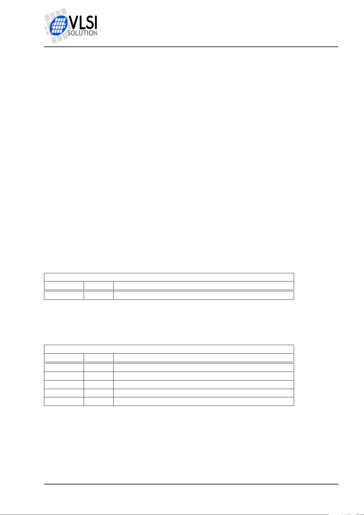
6.1.1 Application Instruction Memory Map (32-bit words)
Free instruction memory for applications
Start Addr Length Description
0x50 0x3B0 Full I memory except jump vectors.
6.1.2 Application X Data Memory Map (16-bit words)
Free X data memory for applications
Start Addr Length Description
0x400 0x1400 _xTemp
0x1800 0x80 User area
0x1C80 0x180 Extra area 1
0x1E40 0x1C0 Extra area 2
0x2080 0x1F80 Extra area 3
Version: 0.40, 2011-09-02 16
PRELIMINARY
Page 17
VS1063a Prog. Guide
6 WRITING USER APPLICATIONS THAT TAKE FULL CONTROL OVER VS1063A
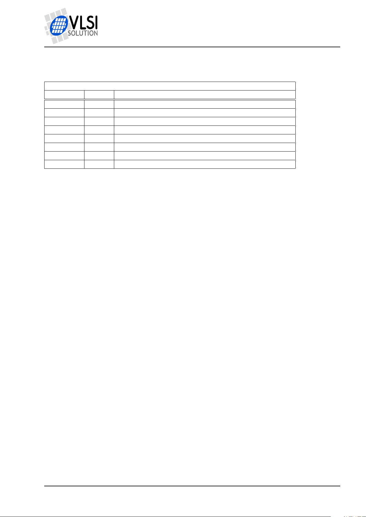
6.1.3 Application Y Data Memory Map (16-bit words)
Free Y data memory for applications
Start Addr Length Description
0x1000 0x800 _g_dcthi
0x1800 0x80 User area
0x1C00 0x2400 _mallocAreaY
0xE000 0xA64 _earSpeaker
0xE000 0xA40 _speedShift
0xEA64 0xFB0 _heAac
0xFA14 0x3EC Extra area
0xFE00 0x200 _pcmFifo
1
These two effects use the same memory area. To be able to use this area, neither EarSpeaker
nor SpeedShift should be used.
1
1
6.2 Taking Control of VS1063a
There are many ways how to take control of VS1063a. Perhaps the most straightforward way
is to take the User Application approach, as explained in Chapter 5.2.
However, instead of a program that would act as a filter and return, the application would
typically start by disabling all interrupts, then running initializations including changing required
interrupt vectors if any, then activating those interrupts needed by the application.
Note: when the user application is called for the first time (and this is the time when we are
taking control of the whole system), and interrupt level is 1 or 2. Because of this, if you want to
use interrupts, you must not only set correct interrupt vectors and activate your own interrupts
using INT_ENABLE, but you also must write twice to register INT_GLOB_ENA (what value
you write doesn’t matter). For details of interrupt control registers, see the VS1063a Hardware
Guide.
Version: 0.40, 2011-09-02 17
PRELIMINARY
Page 18
VS1063a Prog. Guide
6 WRITING USER APPLICATIONS THAT TAKE FULL CONTROL OVER VS1063A
6.2.1 Taking Control of Interrupts
To take control of interrupts, the user first needs to write interrupt handlers. This cannot be
directly done in the C language: stack store and restore operations as well as interrupt reactivation will need to be done in Assembly language.
After an interrupt routine has been written, the corresponding interrupt vector needs to be
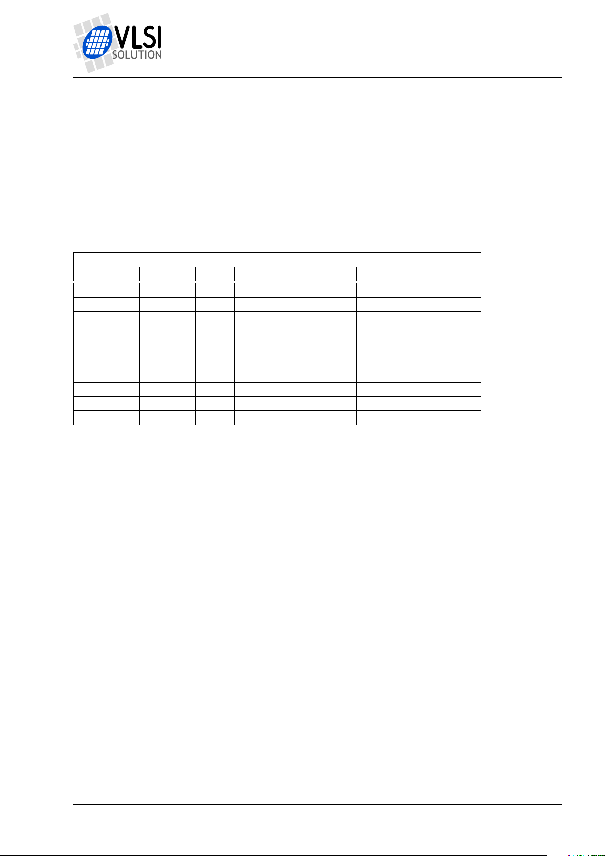
rerouted to the user’s own routine. Interrupt vectors are stored in instruction RAM memory
starting from address 0x20, as shown in the following table:
Interrupt vectors
Name Address Used Default Description
VEC_DAC 0x20 Yes jmpi dac_int,(i6)+1 DAC
VEC_SCI 0x21 Yes jmpi sci_int,(i6)+1 SCI
VEC_SDI 0x22 Yes jmpi _sdi_int,(i6)+1 SDI
VEC_ADC 0x23 Y/N1jmpi modu_int,(i6)+1 ADC
VEC_TX 0x24 No jmpi _empty_int,(i6)+1 UART TX
VEC_RX 0x25 Yes jmpi rx_int,(i6)+1 UART RX
VEC_TIM0 0x26 No jmpi _empty_int,(i6)+1 Timer 0
VEC_TIM1 0x27 No jmpi _empty_int,(i6)+1 Timer 1
VEC_SRC 0x28 Y/N2jmpi src_int,(i6)+1 SampleRate Converter
VEC_SDM 0x29 Y/N3jmpi sdm_int,(i6)+1 Sigma Delta Modulator
1
Active in codec and encoding mode.
2
Active in encoding mode.
3
Active if PCM Mixer or AD Mixer is used.
To replace an interrupt vector, calculate i = 0x2A00000E+a × 0x40, where a is the address of
your own interrupt handler and i is the resulting instruction codeword.
Note: “JMPI” is the only instruction on VS_DSP that doesn’t have delay slot code execution.
Because of this it is also the only VS_DSP instruction that takes two clock cycles to execute
instead of one.
Example: How to take control over the DAC interrupt. First disable the DAC interrupt by clearing
bit 0 of register INT_ENABLE. Do your other initializations. Then calculate your interrupt vector.
E.g. if your own interrupt is at instruction address 0x50, then i =0x2A00000E + 0x50 × 0x40
= 0x2A00140E. Write this value to instruction address 0x20. Then reactivate the interrupt by
setting bit 0 of INT_ENABLE. (Note that disabling and re-enabling the interrupt isn’t necessarily
needed if you don’t care that the old interrupt may occur during your initializations.)
6.3 VSIDE and Applications
VSIDE will get a VS1063a full control application example in Q3/2011.
Version: 0.40, 2011-09-02 18
PRELIMINARY
Page 19
VS1063a Prog. Guide
7 AUDIO FORMAT SPECIFIC COMMENTS
7 Audio Format Specific Comments
7.1 Encoders
7.1.1 VLSI Solution’s Ogg Vorbis Encoder VSOVE v2.00
VLSI Solution’s Ogg Vorbis Encoder VSOVE v2.00 is a continuation of the proprietary VS1053b
Ogg Vorbis encoder originally published in 2007.
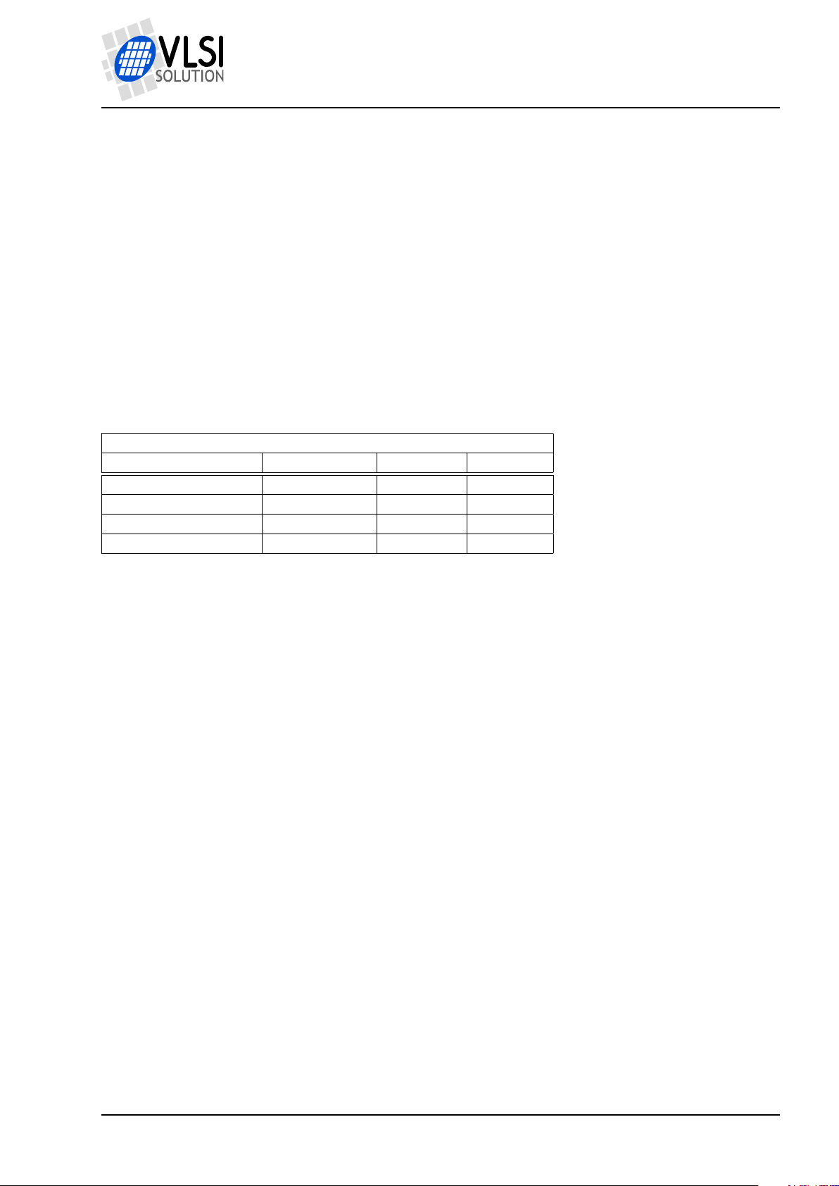
The encoder uses short and long frames as shown in the following table. (Note! A 1024 sample
window in this table corresponds to what the Ogg Vorbis community calls 2048 sample window.)
Ogg Vorbis window lengths as function of samplerate
Nominal Profile / Hz fs / Hz Short Win Long Win
8000 0...9999 64 256
16000 10000...29999 128 512
32000 30000...39999 128 1024
44100 40000...65535 128 1024
Channel coupling is always used for stereo streams. Dual-channel audio is not supported.
For stereo streams, channel coupling is always used (as opposed to MP3, this is a lossless
operation in Ogg Vorbis). However, to save space, part of the audio spectrum is only encoded
as intensity stereo. The frequency threshold for intensity stereo depends on the quality setting.
For quality setting 0, practically all stereo information above 100 Hz is encoded as intensity
stereo. Dual-channel audio like multilingual transmissions using one stereo stream is neither
supported nor recommended.
VSOVE uses VLSI Solution’s proprietary PAMM psycho-acoustic model. PAMM is a noniterative, constant-time, processor-time efficient real-time algorithm that is capable of near CD
quality at bitrates averaging around 140 kbit/s.
VSOVE supports only VBR and makes no attempts at equalizing its output bitrate: the output
file size purely depends on the user-chosen quality setting.
7.1.2 VLSI Solution’s MP3 Encoder VSMPE v1.00
VSMPE is VLSI Solution’s proprietary MP3 encoder first time published for the VS1063 in 2011.
VSMPE supports VBR and CBR.
VSMPE only uses long blocks (576 samples per block).
Version: 0.40, 2011-09-02 19
PRELIMINARY
Page 20
VS1063a Prog. Guide
7 AUDIO FORMAT SPECIFIC COMMENTS
For stereo audio, joint-stereo streams are always created. The encoder determines on a frameby-frame basis whether to use LR-stereo or MS-stereo. Dual-channel audio like multilingual
transmissions using one stereo stream is neither supported nor recommended.
VSMPE uses an enhanced and adapted version of the PAMM psycho-acoustic model originally
devoloped for VLSI Solution’s Ogg Vorbis encoder. The new version of PAMM includes fast
bitrate control which makes it possible to create CBR bitstreams.
When CBR is being used, lowest and highest bitrates may lead into inefficient encoding: lowest
bitrates because the encoder needs to make it sure that the maximum frame length never is
exceeded, and highest bitrates because bit reservoir cannot be trusted too much.
No attempts are made at encoding frequencies over 16 kHz, even with the highest quality settings and samplerates. The reason for this is an omission in the MP3 format specification which
makes it difficult to encode these frequencies with reasonable accuracy.
7.2 Decoders
7.2.1 MP3 Decoder
VS1063a’s MP3 decoder is a full-accuracy decoder.
Version: 0.40, 2011-09-02 20
PRELIMINARY
Page 21
VS1063a Prog. Guide
8 VS1063a Load File Formats
8.1 VS1063a Plugin Format
8 VS1063A LOAD FILE FORMATS
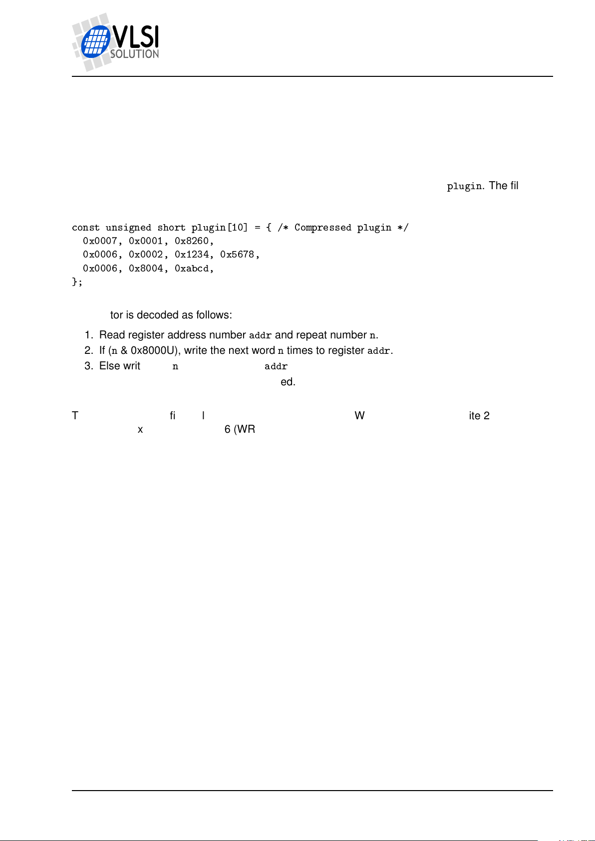
A plugin file (“.PLG”) contains an unsigned 16-bit C source code vector called
is in an RLE compressed format. An example plugin vector is shown below:
const unsigned short plugin[10] = { /* Compressed plugin */
0x0007, 0x0001, 0x8260,
0x0006, 0x0002, 0x1234, 0x5678,
0x0006, 0x8004, 0xabcd,
};
The vector is decoded as follows:
1. Read register address number
2. If (n& 0x8000U), write the next wordntimes to register
3. Else write nextnwords to register
4. Continue until table has been exhausted.
The example vector first tells to write 0x8260 to register 7 (WRAMADDR). Then write 2 words,
0x1234 and 0x5678, to register 6 (WRAM). Finally, write 0xabcd 4 times to register 6 (WRAM).
addr
and repeat numbern.
addr
.
addr
.
plugin
. The file
8.1.1 The .PLG Format and VSIDE
VSIDE will gain the capability of generating plugin format files in Q3/2011.
Version: 0.40, 2011-09-02 21
PRELIMINARY
Page 22
VS1063a Prog. Guide
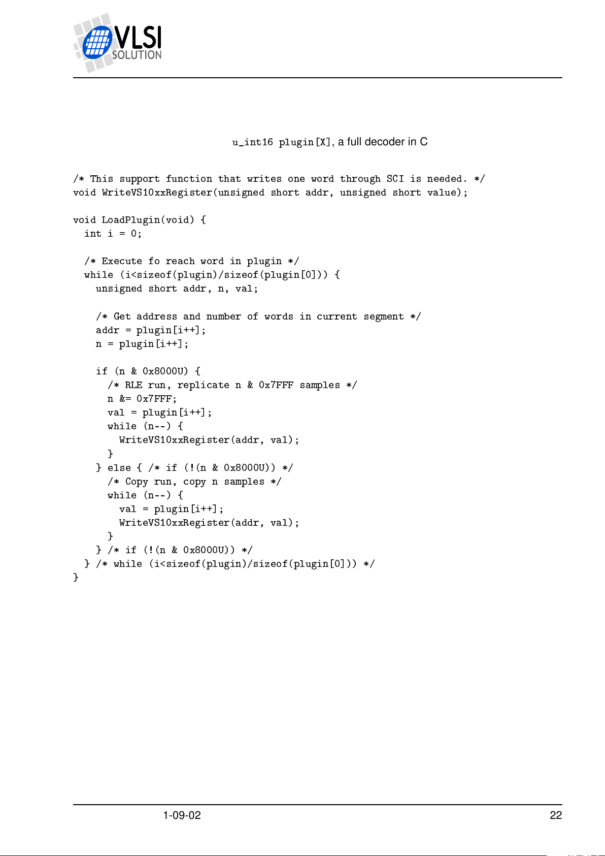
8.1.2 Example VS1063a Microcontroller Plugin Decoder
8 VS1063A LOAD FILE FORMATS
Assuming the vector is in vector
below:
/* This support function that writes one word through SCI is needed. */
void WriteVS10xxRegister(unsigned short addr, unsigned short value);
void LoadPlugin(void) {
int i = 0;
/* Execute fo reach word in plugin */
while (i<sizeof(plugin)/sizeof(plugin[0])) {
unsigned short addr, n, val;
/* Get address and number of words in current segment */
addr = plugin[i++];
n = plugin[i++];
if (n & 0x8000U) {
/* RLE run, replicate n & 0x7FFF samples */
n &= 0x7FFF;
val = plugin[i++];
while (n--) {
WriteVS10xxRegister(addr, val);
}
} else { /* if (!(n & 0x8000U)) */
/* Copy run, copy n samples */
while (n--) {
val = plugin[i++];
WriteVS10xxRegister(addr, val);
}
} /* if (!(n & 0x8000U)) */
} /* while (i<sizeof(plugin)/sizeof(plugin[0])) */
}
u_int16 plugin[X]
, a full decoder in C language is provided
Version: 0.40, 2011-09-02 22
PRELIMINARY
Page 23
VS1063a Prog. Guide
8 VS1063A LOAD FILE FORMATS
8.2 VS1063a Image Format
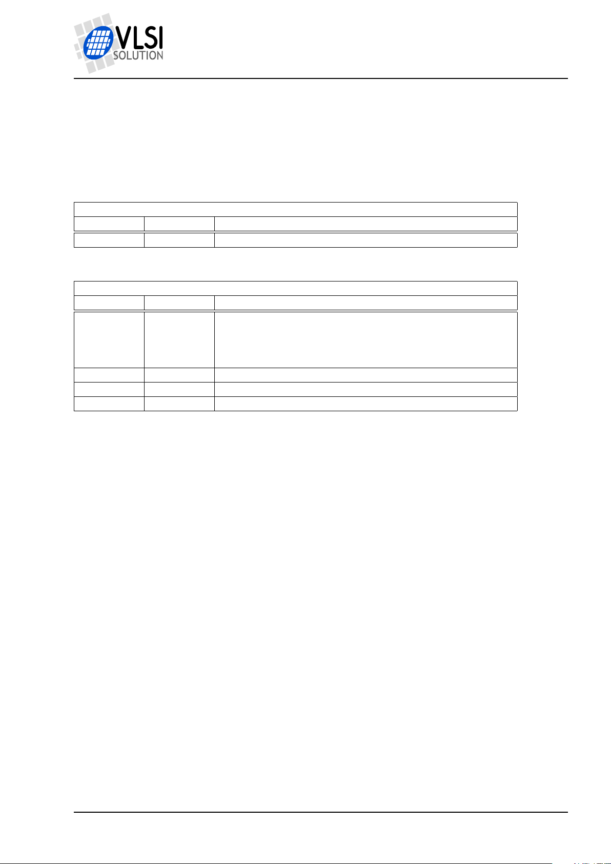
The VS1063a image format is a bootable / loadable binary format with a three-byte header,
followed by one or more boot records. The default image file suffix is “.IMG”.
The 3-byte header is shown below:
VS1063a Boot Header, begins the file
Name Bytes Description
HEADER 3 “P&H” (0x50, 0x26, 0x48)
A boot record is shown below:
VS1063a Boot Record, from 1 to n, last is always TYPE = Execute
Name Bytes Description
TYPE 1 0 = Instruction memory
1 = X data memory
2 = Y data memory
3 = Execute
L1 L0 2 LEN = 256×L1 + L0
A1 A0 2 ADDR = 256×A1 + A0
D1 D0 LEN DATA = 256×D1 + D0, repeat LEN/2 times
The last boot record is always with TYPE = Execute. When an execute record is found, ADDR
is the start address of the application.
The VS1063a boot sequence will skip any unknown records.
8.2.1 The .IMG Format and VSIDE
VSIDE can create prommer image files that are in the VS1063a image format.
Version: 0.40, 2011-09-02 23
PRELIMINARY
Page 24
VS1063a Prog. Guide
8 VS1063A LOAD FILE FORMATS
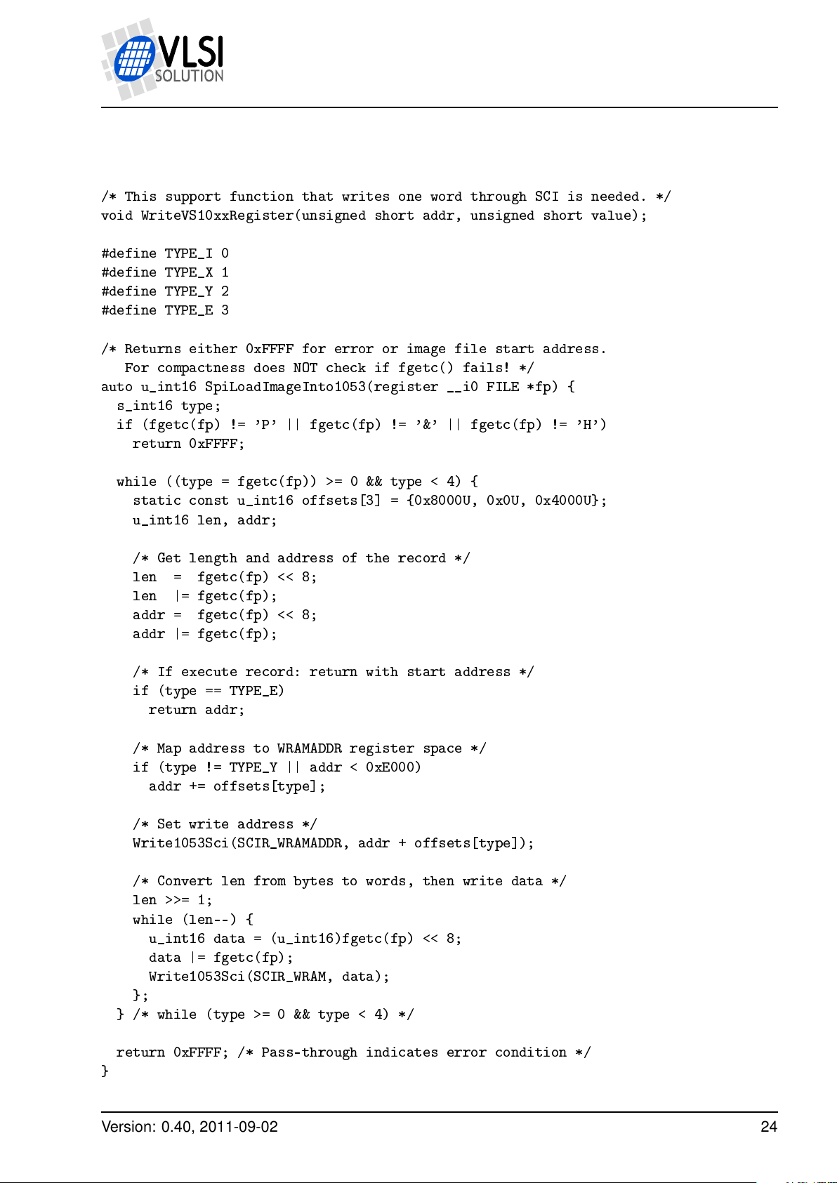
8.2.2 Example VS1063a Microcontroller Boot Image Decoder
/* This support function that writes one word through SCI is needed. */
void WriteVS10xxRegister(unsigned short addr, unsigned short value);
#define TYPE_I 0
#define TYPE_X 1
#define TYPE_Y 2
#define TYPE_E 3
/* Returns either 0xFFFF for error or image file start address.
For compactness does NOT check if fgetc() fails! */
auto u_int16 SpiLoadImageInto1053(register __i0 FILE *fp) {
s_int16 type;
if (fgetc(fp) != 'P' || fgetc(fp) != '&' || fgetc(fp) != 'H')
return 0xFFFF;
while ((type = fgetc(fp)) >= 0 && type < 4) {
static const u_int16 offsets[3] = {0x8000U, 0x0U, 0x4000U};
u_int16 len, addr;
/* Get length and address of the record */
len = fgetc(fp) << 8;
len |= fgetc(fp);
addr = fgetc(fp) << 8;
addr |= fgetc(fp);
/* If execute record: return with start address */
if (type == TYPE_E)
return addr;
/* Map address to WRAMADDR register space */
if (type != TYPE_Y || addr < 0xE000)
addr += offsets[type];
/* Set write address */
Write1053Sci(SCIR_WRAMADDR, addr + offsets[type]);
/* Convert len from bytes to words, then write data */
len >>= 1;
while (len--) {
u_int16 data = (u_int16)fgetc(fp) << 8;
data |= fgetc(fp);
Write1053Sci(SCIR_WRAM, data);
};
} /* while (type >= 0 && type < 4) */
return 0xFFFF; /* Pass-through indicates error condition */
}
Version: 0.40, 2011-09-02 24
PRELIMINARY
Page 25
VS1063a Prog. Guide
9 LATEST DOCUMENT VERSION CHANGES
9 Latest Document Version Changes
This chapter describes the most important changes to this document.
Version 0.40, 2011-09-02
• Minor corrections.
Version 0.30, 2011-05-20
• First publication.
• Still missing chapters: ROM Functions, VS1063a Startup.
Version: 0.40, 2011-09-02 25
PRELIMINARY
Page 26
VS1063a Prog. Guide
10 CONTACT INFORMATION
10 Contact Information
VLSI Solution Oy
Entrance G, 2nd floor
Hermiankatu 8
FI-33720 Tampere
FINLAND
Fax: +358-3-3140-8288
Phone: +358-3-3140-8200
Email: sales@vlsi.fi
URL: http://www.vlsi.fi/
Version: 0.40, 2011-09-02 26
PRELIMINARY
 Loading...