

Page 1

Video-Einspeiser
VL2-CCC
BMW Monitore
mit 10-Pin LVDS Anschluss
Video-Einspeiser mit 2 Video-Eingängen+ RGB- + Rückfahrkamera-Eingang
und CAN-Steuerung
Version 08.04.2011
Page 2

Seite2
Inhaltsverzeichnis
1. Vor der Installation
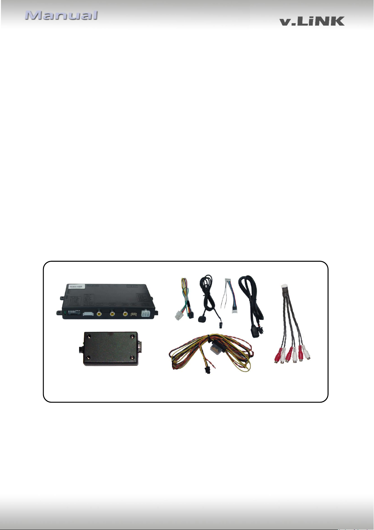
1.1. Lieferumfang
1.2. Überprüfen der Interface-Kompatibilität mit Fahrzeug und Zubehör
1.3. Einstellungen der Dip-Schalter
1.3.1. Fahrzeugauswahl (Dip 6-8)
1.3.2. Aktivierung der Interface-Video-Eingänge (Dip 1-3)
1.3.3. Rückfahrkamera-Einstellungen (Dip 5)
2. Installation
2.1. Installationsort
2.2. Anschlüsse
2.3. Installationsablauf - Funktions-Check
2.4. Bildeinstellungen
2.5. Einspeisung der Audioquellen
2.6. Anschluss von 2 AV-Quellen
3. Bedienung des Interface
3.1. Über Werks-Infotainment-Tasten
3.2. Über externen Taster
4. Technische Daten
5. Technischer Support
Rechtlicher Hinweis
Der Fahrer darf weder direkt noch indirekt durch bewegte Bilder während der Fahrt
abgelenkt werden. In den meisten Ländern/Staaten ist dieses gesetzlich verboten. Wir
schließen daher jede Haftung für Sach- und Personenschäden aus, die mittelbar sowie
unmittelbar durch den Einbau sowie Betrieb dieses Produkts verursacht wurden. Dieses
Produkt ist, neben dem Betrieb im Stand, lediglich gedacht zur Darstellung stehender Menüs
(z.B. MP3 Menü von Nachrüst-DVD-Playern) oder Bilder der Rückfahrkamera während der
Fahrt.
Veränderungen/Updates der Fahrzeugsoftware können die Funktionsfähigkeit des Interface
beeinträchtigen. Softwareupdates für unsere Interfaces werden Kunden bis zu einem Jahr
nach Erwerb des Interface kostenlos gewährt. Zum Update muss das Interface frei
eingeschickt werden. Kosten für Ein- und Ausbau werden nicht erstattet.
Version 08.04.2011 VL2-CCC
Page 3

Seite3
Seriennummer des Interface notieren und Manual aufbewahren für SupportZwecke: ____________________
Produktfeatures
RGB-Eingang für After-Market Navigation
2 Video-Eingänge für Nachrüstgeräte (z.B. DVD-Player, DVB-T Tuner, …)
Eingebauter Audio-Switch
Rückfahrkamera-Eingang mit automatischer Umschaltung
kompatibel mit Werks-Rückfahrkamera
Umschaltung der Videoquellen durch Werks-Infotainment-Tasten
Umschaltung der Videoquellen durch externen Taster
AV-Eingänge PAL/NTSC kompatibel
Ultra-Breitbild-Modus 24:9 (nur bei Ultrawide-Monitor 8.8”)
Schutzschaltung im Falle eines falschen Anschlusses
1. Vor der Installation
Vor der Installation sollte dieses Manual durchgelesen werden. Für die Installation sind
Fachkenntnisse notwendig. Der Installationsort des Interface muss so gewählt werden, dass
es weder Feuchtigkeit noch Hitze ausgesetzt ist.
1.1. Lieferumfang
Version 08.04.2011 VL2-CCC
Page 4
Seite4
Voraussetzungen
Generell Monitor mit 10-Pin LVDS-Anschluss
BMW
Fahrzeug 3er (E90/91/92), 5er (E60/61),
6er (E63/64), X5 (E70), X6 (E71) und andere Fahrzeuge
Navigation/Radio Professional Navigationssystem CCC Business Navigationssystem M-ASK bis ca. 2009 Radio mit Farbmonitor
Einschränkungen
Ultra-Breitbild-Modus Nur verfügbar für Ultrawide-Monitore 8.8”
Nur Video Das Interface speist NUR das Video-Signal in das Info-
tainment ein. Um Sound einzuspeisen, können ein FMModulator, der Werks-AUX-Eingang, der beim Händler
kodiert werden kann, unsere OBD-Aktivatoren, wenn nicht
im Fahrzeug vorhanden, das AUX-In Interface AUX-110
oder ein Dension Gateway 500 genutzt werden.
Fahrzeug/ Navigation
Dip 6
Dip 7
Dip 8
BMW CCC mit 8.8” Ultrawide-Monitor
OFF
ON
OFF
BMW CCC mit 6.5”-Monitor
OFF
ON
ON
1.2. Überprüfen der Interface-Kompatibilität mit Fahrzeug und Zubehör
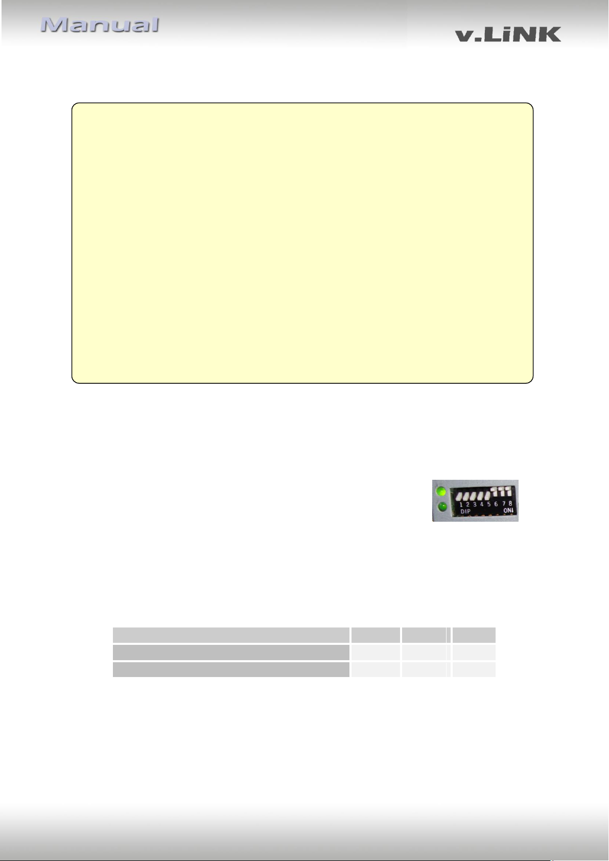
1.3. Einstellungen der Dip-Schalter
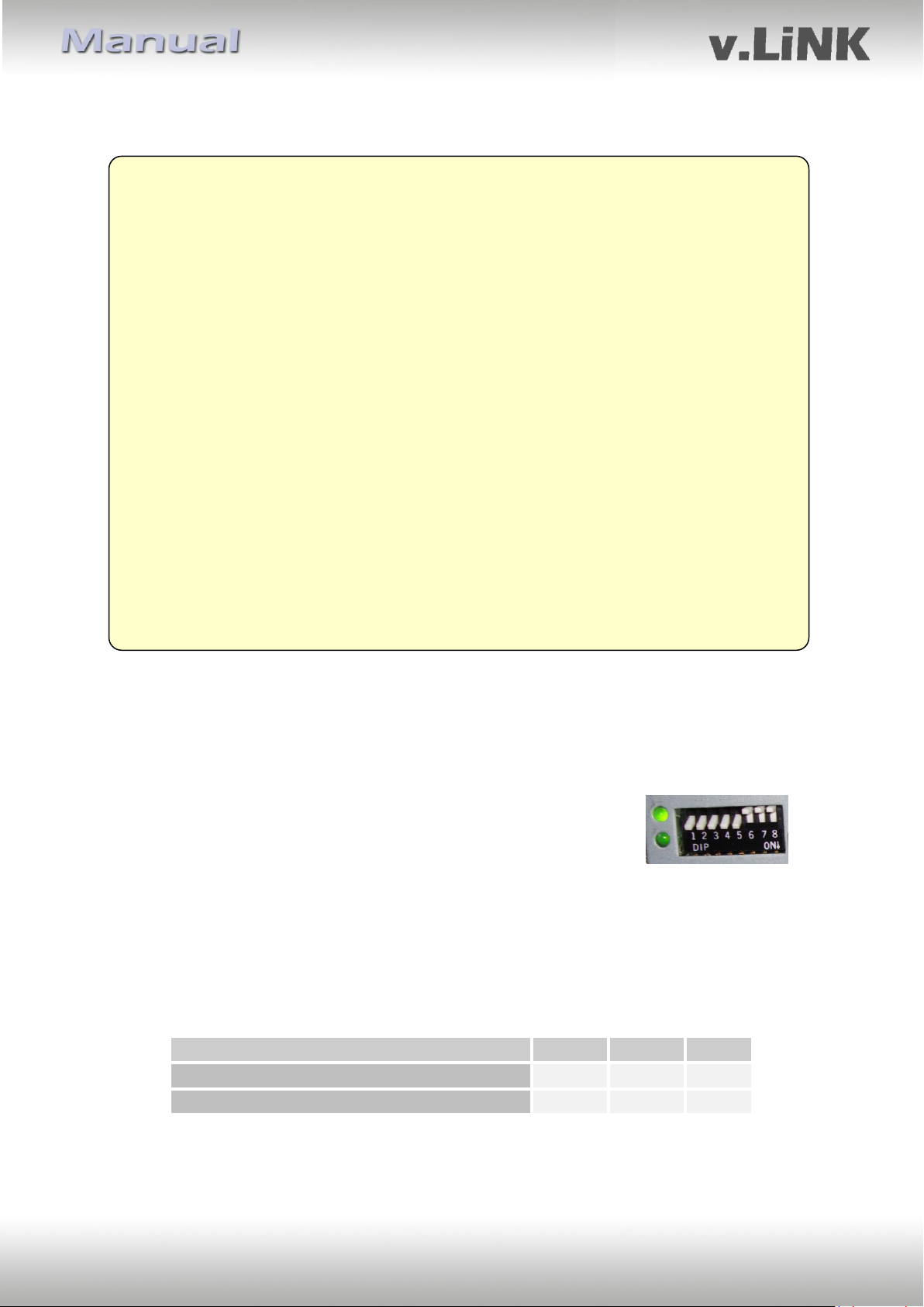
Mit den Dip-Schaltern der Video-Interface-Box ist es möglich, das Fahrzeug bzw. die
Navigation auszuwählen, in die das Interface eingebaut werden soll (Dip 6 bis 8), die
Interface-Video-Eingänge zu aktivieren bzw. zu deaktivieren (Dip 1
bis 3) und die Art der Kamera auszuwählen, die installiert ist bzw.
installiert werden soll (Dip 5).
Dip Position “unten” ist ON und Position “oben” ist OFF.
1.3.1. Fahrzeugauswahl (Dip 6 bis 8)
Wählen Sie Fahrzeug/Navigation/Monitor, in die das Interface installiert werden soll, aus
und stellen Sie Dip 6 bis 8 entsprechend der folgenden Tabelle ein.
Version 08.04.2011 VL2-CCC
Page 5

Seite5
Dip
Video-Eingang
ON (unten)
OFF (oben)
Dip 1
RGB
aktiviert
deaktiviert
Dip 2
Video IN1
aktiviert
deaktiviert
Dip 3
Video IN2
aktiviert
deaktiviert
Art der
Rückfahrkamera
Dip 5
Keine
OFF
Werk
OFF
After-Market
ON
1.3.2. Aktivierung der Interface-Video-Eingänge (Dip 1-3)
Nur auf die aktivierten Video-Eingänge kann beim Umschalten auf die Video-Quellen
zugegriffen werden. Es wird empfohlen, nur die erforderlichen Eingänge zu aktivieren. Die
deaktivierten Eingänge werden beim Umschalten ausgelassen.
1.3.3. Rückfahrkamera-Einstellungen (Dip 5)
Je nachdem, ob keine Kamera, eine After-Market-Kamera oder
eine Werks-Kamera angeschlossen wird, muss die Dip 5
Einstellung unterschiedlich sein. Bei Dip-Schalterstellung OFF
schaltet das Interface solange der Rückwärtsgang eingelegt ist auf
Werk-LVDS Bild für vorhandene Werks-Rückfahrkamera oder
Werks-PDC Darstellung.
2. Installation
Zündung ausstellen und Fahrzeugbatterie nach Werksangaben abklemmen!
Darf gemäß Werksangaben die Fahrzeugbatterie nicht abgeklemmt werden,
reicht es in den meisten Fällen aus, das Fahrzeug in den Sleep-Modus zu
versetzen. Sollte dieses nicht funktionieren, kann die Fahrzeugbatterie mit
einer Widerstandsleitung abgeklemmt werden.
Das Interface benötigt Dauerstrom. Kommt die Spannungsversorgung nicht
direkt von der Fahrzeugbatterie, muss überprüft werden, ob die Spannungsversorgung dauerhaft und startstabil ist.
2.1. Installationsort
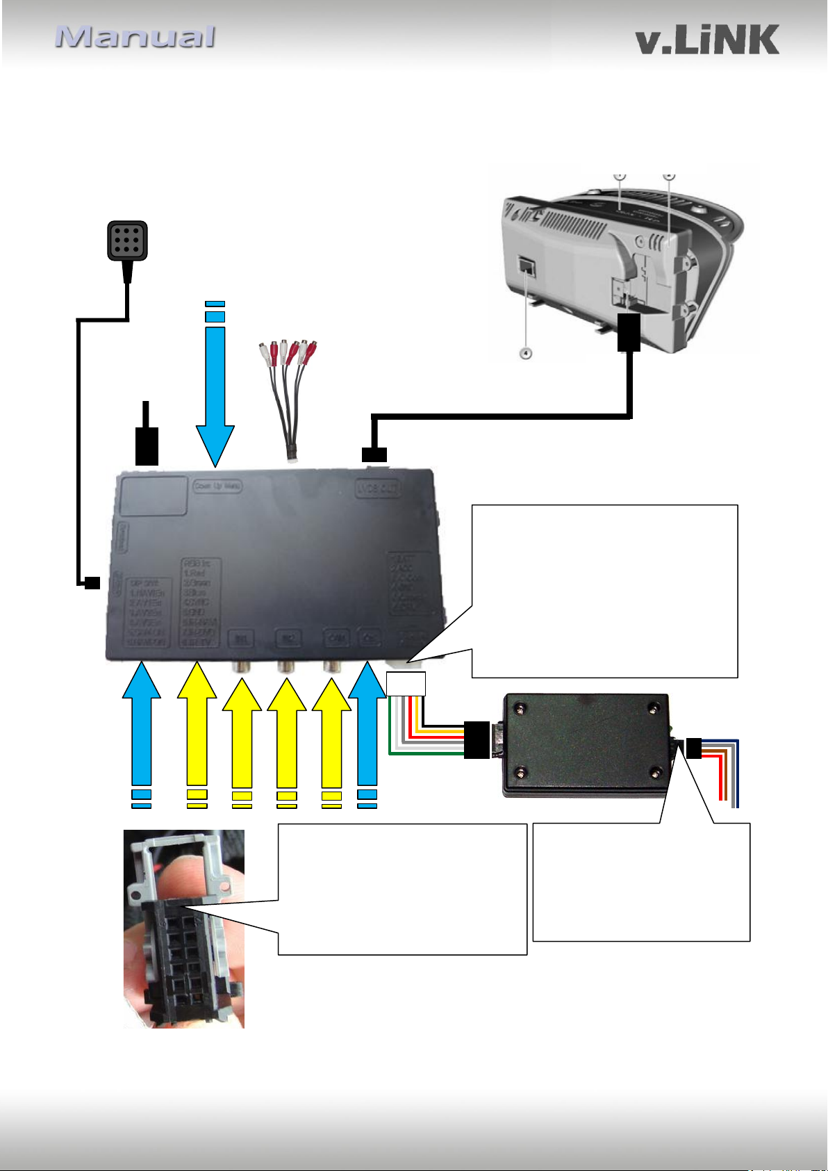
Das Interface wird an der Rückseite des Fahrzeugmonitors installiert.
Version 08.04.2011 VL2-CCC
Page 6
Seite6
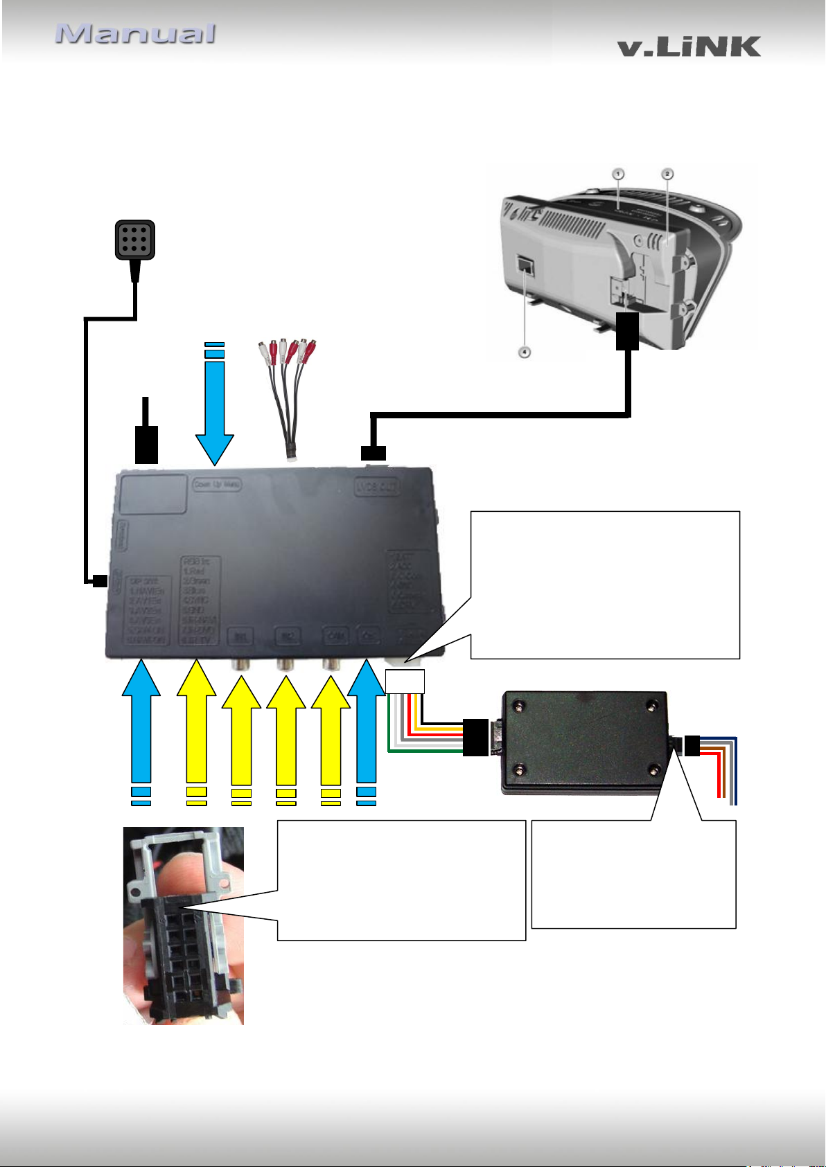
4-Pin Kabel
10-Pin Interface LVDS
Kabel
Video-Interface
DIP Schalter
RGB Eingang
Video-IN1
Video-IN2
Kamera-IN
10-Pin LVDS
Buchse des
Interface
Kabelbaums
Pin-Belegung weißer 6-Pin Stromanschluss
Pin 1 (gelb) - ACC oder Batterie +12V
Pin 2 (rot) - ACC +12V
Pin 3 (grau) - IR-Daten
Pin 4 (schwarz) - Masse
Pin 5 (grün) - Steuerung Eingang
Rückfahrkamera +12V
Pin 6 (weiß) - AV-Umschaltsignal
CAN Box
Pin-Belegung schwarzer 4-Pin
Stromanschluss
Pin 4 (rot) - Batterie+12V
Pin 2 (braun) - Masse
Pin 1 (grau) - CAN low
Pin 3 (blau) - CAN high
Externer Taster für
Wechsel der Video-
Quellen
(Zusatzoption)
Keine Haftung für Kabelfarben und Pin-Belegungen des
Fahrzeugs!
Änderungen des Fahrzeugherstellers möglich. Die angegebenen
Informationen müssen vom Installateur überprüft werden.
6-Pin auf
8-Pin Kabel
CTRL-port
10-Pin LVDS Buchse
des Fahrzeug-
Kabelbaums
Bildeinstellungen
Rückseite Werks-
Monitor
Pin-Belegung 12-Pin Strombuchse des
Werksmonitors
Pin 2 (Violett/rot) - Batterie+12V
Pin 3 (schwarz/braun) - Masse
Pin 6 (gelb) - CAN low
Pin 5 (schwarz) - CAN high
CAN-Kabel sind verdrillt.
AudioKabel
2.2. Anschlüsse
Version 08.04.2011 VL2-CCC
Page 7

Seite7
2.3. Installationsablauf – Funktions-Check
Befolgen Sie den folgenden Installationsablauf und nutzen Sie das Schema unter Kapitel 2.2.
als Referenz. Vor der Installation empfehlen wir eine erste kurze Verbindung und einen
Testlauf, um sicherzustellen, dass Fahrzeug und Interface kompatibel sind. Aufgrund von
Änderungen in der Produktion des Fahrzeugherstellers besteht immer die Möglichkeit der
Inkompatibilität.
- Zündung ausstellen und Fahrzeugbatterie nach Werksangaben abklemmen
- Fahrzeugmonitor ausbauen
- 12-Pin Strombuchse vom Werksmonitor abstecken
- 4-Pin Kabel der CAN-Box mit an 12-Pin Stromstecker des Werksmonitors anschließen
- 12-Pin Strombuchse wieder Werksmonitor einstecken
- 4-Pin Kabel an CAN-Box anschließen
- 8-Pin Buchse des 6-Pin auf 8-Pin Kabels an die CAN-Box anschließen
- 10-Pin LVDS Buchse des Fahrzeugkabelbaums vom Werksmonitor abstecken und in
den 10-Pin LVDS Anschlussstecker des Video-Interface einstecken
- 10-Pin LVDS Anschlussstecker des Werksmonitors und LVDS Ausgang des Video-
Interface mit dem 10-Pin Interface LVDS Kabel verbinden
- 6-Pin Buchse des 6-Pin auf 8-Pin Kabels an das Video-Interface anschließen
- Externen Taster an den “Switch”-Anschluss anschließen. Auch wenn der Taster nicht
genutzt werden soll, wird die Installation (z.B. an einer versteckten Stelle) für
Support-Zwecke empfohlen
- Wenn 2 Audio-Quellen genutzt werden sollen, entsprechend Kapitel 2.6. anschließen
- Batterie wieder an klemmen und Zündung einschalten
- LEDs der CAN-Box und des Video-Interfaces überprüfen, eine an
jedem muss leuchten
- Videoquellen über die Infotainment-Tasten (siehe Kapitel 3.1.) und über das
Tastenfeld (siehe Kapitel 3.2.) testweise aktivieren. Dazu ein Testbild als Quelle
verwenden
- Wenn eine Kamera angeschlossen ist (oder werden soll), den Rückwärtsgang
einlegen und mit Testbild als Quelle testen
- Wenn 2 Audio-Quellen genutzt werden sollen, Audio-Kabel verbinden und Audio-
Funktion testen
- NUR nach erfolgreichem Funktionscheck mit der endgültigen Installation der
Videoquellen fortfahren!
- Nach Installation und Verbindung der Videoquelle(n), die Bildeinstellungen anpassen
(siehe Kapitel 2.4.)
Version 08.04.2011 VL2-CCC
Page 8
Seite8
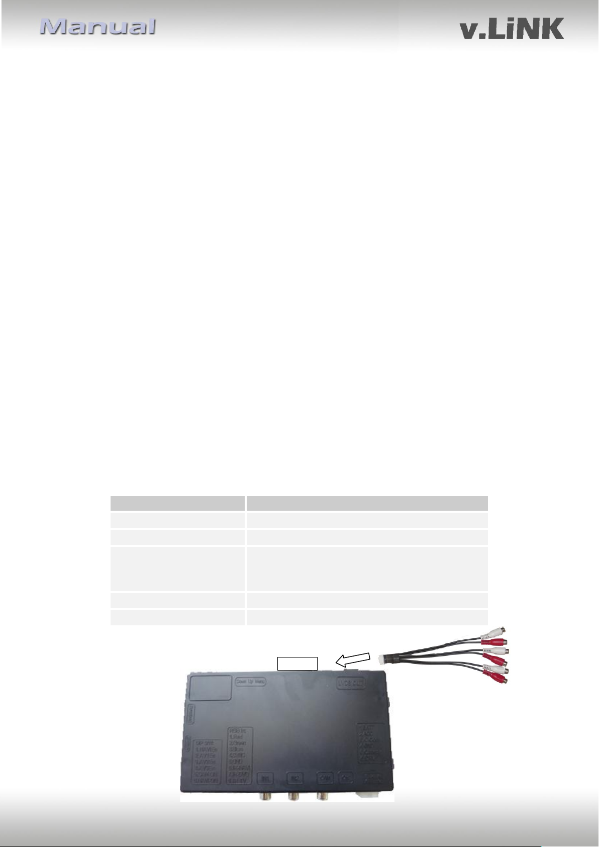
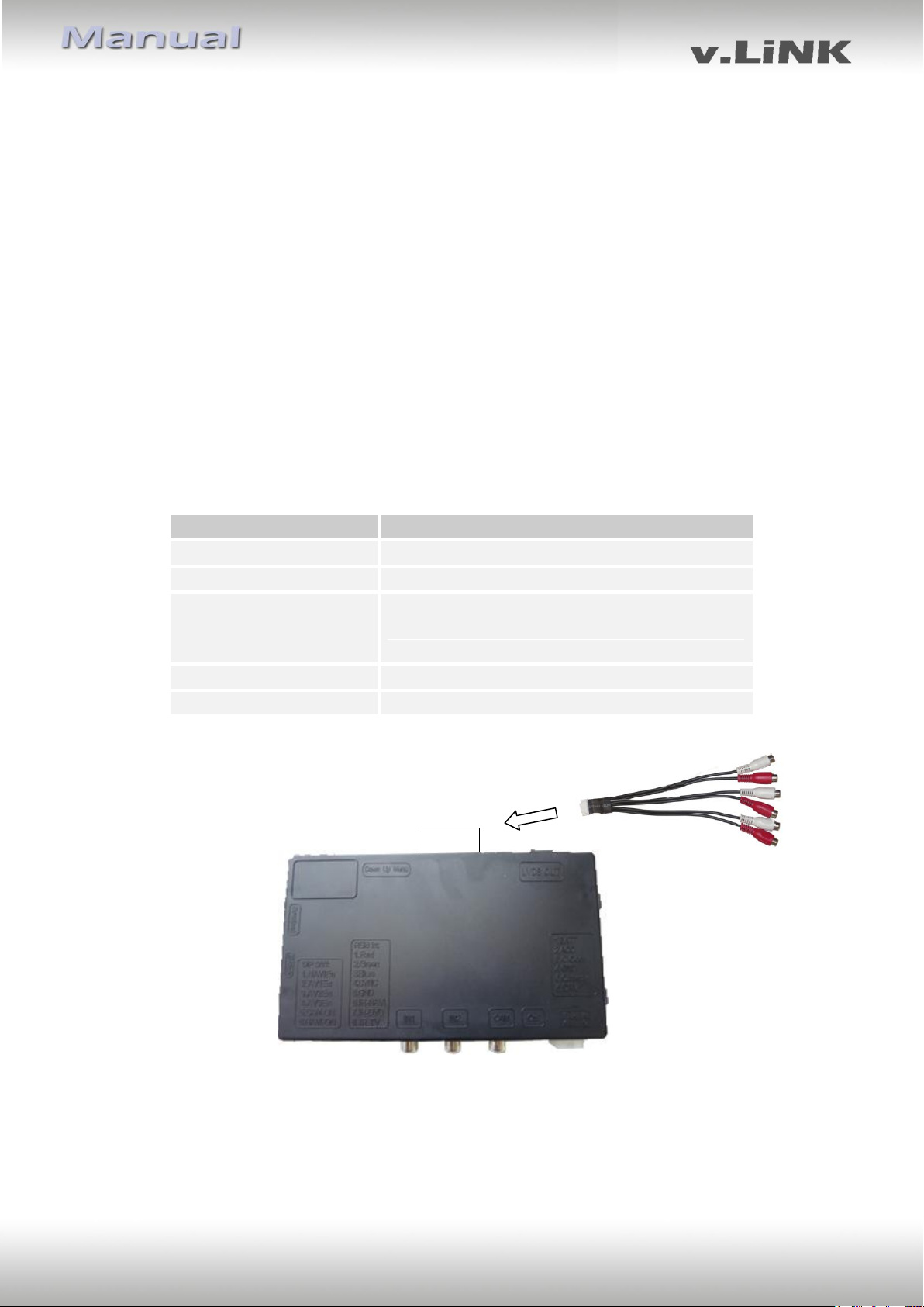
Audio Pins
Belegung
1/2
Audio-Eingangssignal R/L der Quelle IN2
3/4
Audio-Eingangssignal R/L der Quelle IN1
5/6
Audio-Ausgangssignal R/L des Werks-AUX,
AUX-110, Dension Gateway 500 oder FMModulators
7
Masse
8
Keine Funktion
Audio-Kabel
Video-Interface
Audio-Switch-
Anschluss
2.4. Bildeinstellungen
Nach der Installation der Video-Quellen können die Bildeinstellungen durch Benutzen eines
Stiftes auf den Tasten des Video-Interfaces verändert werden. Durch Drücken der Taste
MENU kann das Menü Einstellungen auf dem OSD geöffnet und zur nächsten Einstellung
gewechselt werden. UP und DOWN verändert die entsprechenden Einstellungen.
Die Tasten sind in das Gehäuse eingelassen, um unbeabsichtigte Veränderungen während
und nach der Installation zu vermeiden.
2.5. Einspeisung der Audioquellen
Dieses Interface kann nur Video-Signale in das Werks-Infotainment einspeisen. Das
eingespeiste Video-Signal kann parallel zu jedem Audio-Modus des Werks-Infotainments
aktiviert werden. Wenn eine AV-Quelle angeschlossen wird, ist der Videoausgang der Quelle
mit Video IN1 des Video-Interface und der Audio-Ausgang der Quelle mit der AudioEinspeisung verbunden. Audio-Einspeisung ist über das optional erhältliche AUX-In Interface
AUX-110, den Werks-Audio-AUX-Eingang, einen Dension Gateway 500 oder einen FMModulator möglich. Der Werks-Audio-AUX kann bereits im Fahrzeug vorhanden sein. Wenn
nicht vorhanden, kann er in den meisten Infotainments, die mit diesem Interface kompatibel
sind, beim Händler oder über einen unserer OBD-CCC-X-xx-Aktivatoren kodiert werden.
2.6. Anschluss von 2 AV-Quellen
Wenn 2 AV-Quellen angeschlossen werden sollen, das beiliegende Audio-Kabel an den
Audio-Switch-Anschluss des Video-Interface anschließen. Beim Umschalten des VideoInterface von Video-IN1 auf Video-IN2 wird auch das Audio-Signal automatisch
umgeschaltet.
Version 08.04.2011 VL2-CCC
Page 9
Seite9
3. Bedienung des Interface
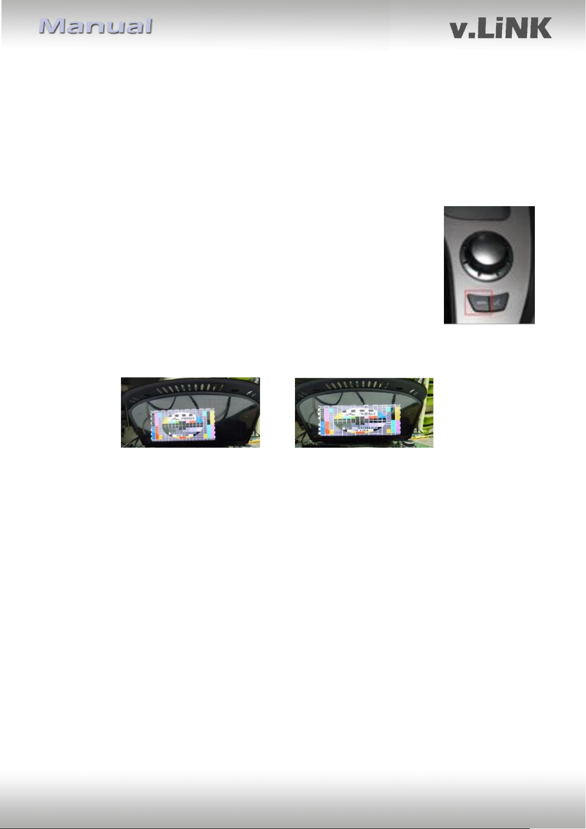
3.1. Über Werks-Infotainment-Tasten
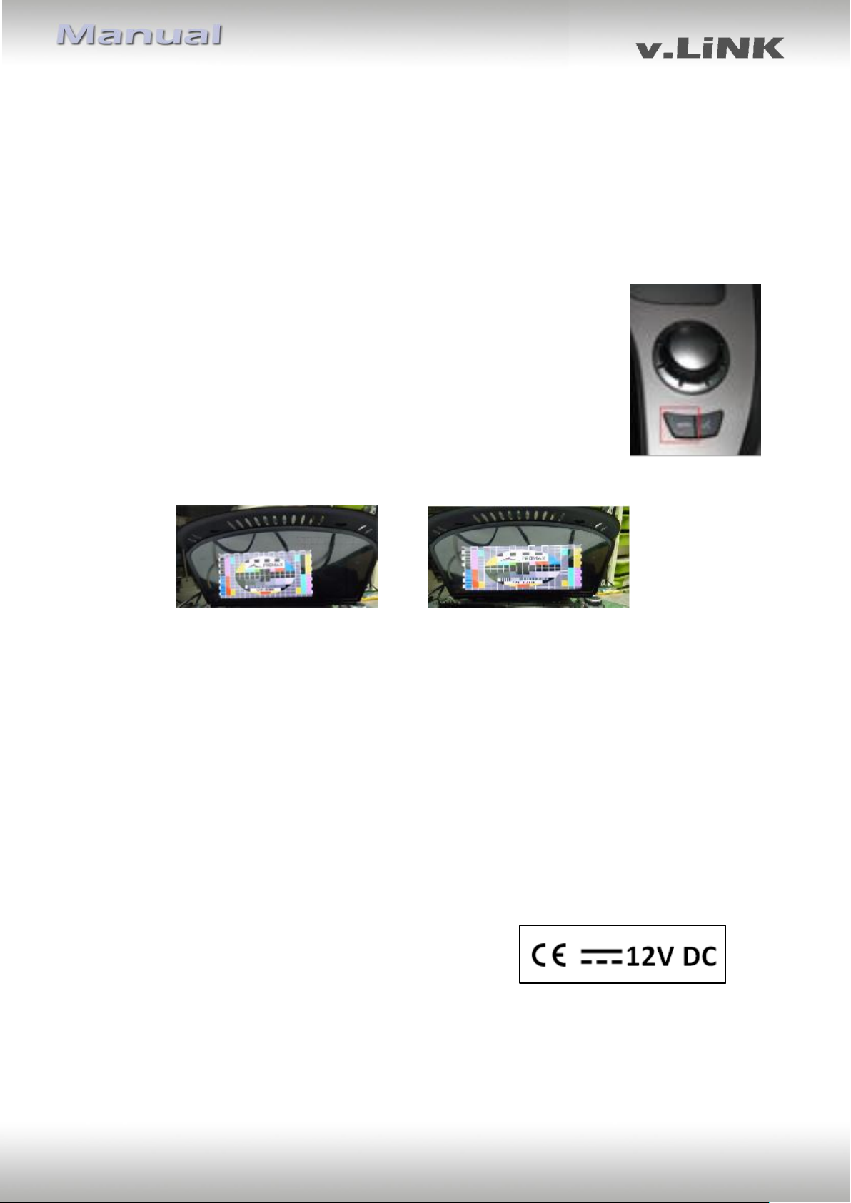
Einige der Werks-Infotainment-Tasten können für die Bedienung des Interface genutzt
werden.
Taste MENÜ drücken (länger als 1 Sekunde) zum Umschalten der Video-Quelle. Jedes
Drücken (länger als 1 Sekunde) wechselt zum nächsten aktivierten Eingang. Wenn alle
Eingänge aktiviert sind, ist die Reihenfolge:
Werks-Video RGB-in Video IN1 Video IN2 Werks-Video …
Nicht aktivierte Eingänge werden übersprungen. Wenn das Audio-Kabel
angeschlossen ist, wird beim Umschalten von Video-IN1 auf Video-IN2
auch das Audio-Signal automatisch umgeschaltet.
Im Interface-Video-Modus die Taste MENÜ lange drücken (länger als
3 Sekunden) zum Umschalten der Bildformate 16:9 und 24:9 (nur bei Fahrzeugen mit
Ultrawide Bildschirm 8.8“).
3.2. Über externen Taster
Der externe Taster kann alternativ oder zusätzlich zu den Werk-Infotainment-Tasten zur
Steuerung der Interface-Funktionen verwendet werden.
Taster kurz drücken – Umschaltung Video-Eingänge, wie MENÜ drücken, siehe Kapitel 3.1.
Taster lange drücken – Umschaltung Bildformate, wie MENÜ lange drücken,
siehe Kapitel 3.1.
Version 08.04.2011 VL2-CCC
Page 10

Seite10
4. Technische Daten
Arbeitsspannung 7V ~ 25V
Stromaufnahme 0.3A @12V
Video Eingang 0.7V~1V
Video Eingang Formate PAL/NTSC
Gewicht 195g
Abmessungen (nur Box) B x H x T 182 x 24 x 100 mm
5. Technischer Support
NavLinkz GmbH Caraudio-Systems Vertriebs GmbH
Vertrieb/Techn. Support Vertrieb
Eurotec-Ring 45 Rheinhorststr. 22
D-47445 Moers D-67071 Ludwigshafen am Rhein
Tel +49 2841 949970
Email [email protected]
Version 08.04.2011 VL2-CCC
Page 11

Video-inserter
VL2-CCC
BMW monitors
with 10pin LVDS connector
Video-inserter with 2 video + RGB + rear-view camera input and CAN control
Version 08.04.2011
Page 12

page2
Contents
1. Prior to installation
1.1. Delivery contents
1.2. Checking the compatibility of vehicle and accessories
1.3. Dip-switch settings
1.3.1. Vehicle selection (dip 6-8)
1.3.2. Enabling the interface’s video inputs (dip 1-3)
1.3.3. Rear-view camera settings (dip 5)
2. Installation
2.1. Place of installation
2.2. Connections
2.3. Installation procedure – function check
2.4. Picture settings
2.5. Audio insertion
2.6. Connecting 2 AV sources
3. Interface operation
3.1. By factory infotainment buttons
3.2. By keypad
4. Specifications
5. Technical support
Legal Information
The driver must not be distracted by moving pictures. By law, watching mobbing pictures
while driving is prohibited. We do not accept any liability for material damage or personal
injury resulting, directly or indirectly, from the installation or the operation of this TV-free
interface. This Interface should only be used to display fixed menus or rear-view-cam
pictures when the vehicle is moving, for example the MP3 menu for DV upgrades.
Information
Changes of the vehicle software can cause malfunctions of the interface. We offer free
software-updates for interfaces for one year after purchase. To receive a free update, the
interface must be sent in at own cost. Labor cost for and other expenses involved with the
software-updates will not be refunded.
Version 08.04.2011 VL2-CCC
Page 13
page3
Take down the serial number of the interface and store this manual for support
purposes: ____________________
Product features
RGB-input for after-market navigation
2 video-inputs for after-market devices (e.g. DVD-Player, DVB-T tuner, …)
Built-in audio-switch
Rear-view camera input, automatically switching
Factory rear-view camera compatible
Switching of video through factory infotainment buttons
Switching of video through external switch
PAL/NTSC input compatible
Ultra-wide picture mode 24:9 (only BMW with ultra-wide screen 8.8”)
Wrong-plugging circuit protection
1. Prior to installation
Read the manual prior to installation.
Technical knowledge is necessary for installation. The place of installation must be free of
moisture and away from heat sources.
1.1. Delivery contents
Version 08.04.2011 VL2-CCC
Page 14
page4
Requirements
General Monitor with 10pin LVDS video connector
Vehicle 3series (E90/91/92), 5series (E60/61),
6series (E63/64), X5 (E70), X6 (E71), and other vehicles
Navigation/Radio Professional Navigation CCC Business Navigation M-ASK up to about 2009 Radio with colour screen
Limitations
Ultra-wide mode Only available for ultra-wide screens 8.8”
Video only The interface inserts ONLY video into the infotainment,
for sound use the FM-modulator or factory AUX which can
be coded by dealership or our OBD-coders if not already
available in the vehicle or the AUX-in interface AUX-110 or
a Dension gateway 500.
Vehicle/Navigation
Dip 6
Dip 7
Dip 8
BMW CCC with 8.8” ultra-wide monitor
OFF
ON
OFF
BMW CIC with 6.5” monitor
OFF
ON
ON
1.2. Checking the compatibility of vehicle and accessories
1.3. Dip-switch settings
With the video interface boxes dip-switches it is possible to select vehicle/navigation the
interface is to be installed in (dip 6 to 8), to dis- or enable the interfaces inputs (dip 1 to 3)
and to preselect the type of camera which is (to be) installed (dip 5).
Dip position down is ON and position up is OFF.
1.3.1. Vehicle selection (dip 6-8)
Choose the vehicle/navigation/monitor the interface is to be installed to and set dip 6
through 8 according to the below table.
Version 08.04.2011 VL2-CCC
Page 15

page5
Dip
Video-input
ON (down)
OFF (up)
Dip 1
RGB
enabled
disabled
Dip 2
Video IN1
enabled
disabled
Dip 3
Video IN2
enabled
disabled
Rear-view
camera type
Dip 5
None
OFF
Factory
OFF
After-market
ON
1.3.2. Enabling the interface’s video inputs (dip 1-3)
Only the enabled video inputs can be accessed when switching through the video sources. It
is recommended to enable only the required inputs for the disabled will be skipped when
switching through the video interfaces inputs.
1.3.3. Rear-view camera settings (dip 5)
Depending on whether no camera, after-market camera or
factory camera shall be used, dip 5 must use different settings.
If set to OFF, the interface switches to factory LVDS picture
when the reverse gear is engaged to display factory rear-view
camera or factory PDC picture.
2. Installation
Switch off ignition and disconnect the vehicle’s battery! The interface needs a
permanent 12V source. If according to factory rules disconnecting the battery
is to be avoided, it is usually sufficient to put the vehicle is sleep-mode. In
case the sleep-mode does not show success, disconnect the battery with a
resistor lead.
If power source is not taken directly from the battery, the connection has to be
checked for being start-up proven and permanent.
2.1. Place of installation
The interface is installed on the backside of the vehicle’s monitor.
Version 08.04.2011 VL2-CCC
Page 16
page6
10pin interface
LVDS cable
Video interface
DIP switches
RGB input
Video-IN1
Video-IN2
Camera-IN
10pin HSD LVDS
female connector of
interface harness
Pin-definition white 6pin
power connector
Pin 1 (yellow) - ACC or Battery +12V
Pin 2 (red) - ACC +12V
Pin 3 (grey) - IR data
Pin 4 (black) - Ground
Pin 5 (green) - Rear-view camera input
Control +12V
Pin 6 (white) - AV-switch signal
CAN box
Pin-definition black 4pin
power connector
Pin 4 (red) - Battery+12V
Pin 2 (brown) - Ground
Pin 1 (grey) - CAN low
Pin 3 (blue) - CAN high
Keypad for video
source switching
(additional option)
Pin-definition 12pin power
connector of factory monitor
Pin 2 (violet/red) - Battery+12V
Pin 3 (black/brown) - Ground
Pin 6 (yellow) - CAN low
Pin 5 (black) - CAN high
CAN wires are twisted.
No liability for vehicle wire colors and pin definition!
Possible changes by the vehicle manufacturer. The given
information must be verified by the installer.
6pin to 8pin
cable
4pin harness
CTRL-port
Backside factory
monitor
10-Pin LVDS
female connector
of vehicle harness
Pic settings
Audio
cable
2.2. Connections
Version 08.04.2011 VL2-CCC
Page 17

page7
2.3. Installation procedure – function check
Follow the below procedure using the “Connections” scheme from chapter 2.2. as reference.
Before the installation of the sources and the interface we recommend a first quick
connection of the interface and test run to ensure that vehicle and product are compatible.
Due to changes in production of the vehicle manufacturer there is always the possibility of
incompatibility.
- Switch off ignition and disconnect vehicle’s battery
- Remove vehicle monitor
- Disconnect 12pin power connector from backside of factory monitor
- Connect 4pin CAN box harness to 12pin power connector of factory harness
- Reconnect 12pin power connector to factory monitor
- Plug 4pin harness into CAN box
- Plug 8pin female connector of 6pin to 8pin cable into CAN box
- Transfer vehicle harness’ 10pin LVDS connector from factory monitor to interface’s
male 10pin connector port
- Connect video-interface LVDS output and factory monitor’s 10pin LVDS port using
the 10pin interface LVDS cable
- Plug 6pin female connector of “6pin to 8pin cable” into video interface
- Plug keypad into “Switch” connector. Even if the keypad shall not be used, its
installation (e.g. in a hidden spot) is recommended for support reasons
- If 2 audio sources shall be used, connect it according to chapter 2.6.
- Reconnect battery and turn on ignition
- Check LEDs on CAN box and video interface, one on each must be on
- Try to activate video sources by infotainment buttons (see chapter 3.1.) and by
keypad (see chapter 3.2.), using a test picture source
- If camera is (to be) connected try to engage reverse gear with test picture source
connected
- If 2 audio sources shall be used, connect the audio wires and check the audio
function
- ONLY after positive function check proceed with final installation of the video
sources!
- After installation and connection of the real video source(s), adjust picture settings
(see chapter 2.4.)
2.4. Picture settings
After installing the sources the picture settings can be changed using a pen on the buttons of
the video interface. Press the MENU button to open settings menu on the OSD and to
switch to the next setting. UP and DOWN change the corresponding values. The buttons are
embedded in the housing to avoid accidental changes during or after installation.
Version 08.04.2011 VL2-CCC
Page 18
page8
Audio pins
Definition
1/2
Audio input signal R/L of source IN2
3/4
Audio input signal R/L of source IN1
5/6
Audio output signal L/R of factory audio AUX,
AUX-110, Dension Gateway 500 or FMmodulator
7
Ground
8
No function
Audio-cable
Video-interface
Audio-switch-
port
2.5. Audio insertion
This interface can only insert video into the factory infotainment. The video can be activated
to any audio mode of the factory infotainment. If an AV-source is to be connected, the
source’s video out is connected to the video IN1 of the video interface and the source’s
audio out to the audio insertion. Audio insertion is possible by the AUX-in interface AUX-110,
factory audio AUX input, a Dension Gateway 500 or FM-modulator. The factory audio AUX
might be already available in the vehicle. If not, on most infotainments which are compatible
with this video interface, it can be coded by the dealership or by using one of our OBD-CCCX-xx coders.
2.6. Connecting 2 AV-sources
If two AV-sources shall be connected, connect the included audio cable to audio-switch-port
of the video interface. When switching the video interface from video-IN1 to video-IN2, the
audio will also automatically be switched.
Version 08.04.2011 VL2-CCC
Page 19
page9
3. Interface operation
3.1. By factory infotainment buttons
Some of the factory buttons can be used to execute interface functions.
Press MENU button (more than 1 second) to activate the interface video. Each press (more
than 1 second) will switch to the next enabled input. If all inputs are enabled the order is:
Factory video RGB-in video IN1 video IN2 factory video …
Inputs which are not enabled are skipped. If the audio cable is connected,
when switching from video IN1 to video IN2, also the sound will be
switched.
When in interface video mode, by long pressing the MENU button
(more than 3 seconds), it is possible to switch the picture ratio between
16:9 and 24:9 (Only on vehicles with ultra-wide 8.8” screen).
3.2. By keypad
Alternatively or additionally to the factory infotainment buttons the interface’s keypad can
be used to execute interface functions.
Shortpress keypad – video input switching, like press MENU, see chapter 3.1.
Longpress keypad – inserted picture ratio switching, like long press MENU, see chapter 3.1.
4. Specifications
BATT/ACC range 7V ~ 25V
Power 0.3A @12V
Video input 0.7V~1V
Video input formats PAL/NTSC
Weight 195g
Dimensions (box only) B x H x T 182 x 24 x 100 mm
Version 08.04.2011 VL2-CCC
Page 20

page10
5. Technical Support
NavLinkz GmbH Caraudio-Systems Vertriebs GmbH
distribution/tech dealer-support distribution
Eurotec-Ring 45 Rheinhorststr. 22
D-47445 Moers D-67071 Ludwigshafen am Rhein
phone +49 2841
email [email protected]
Version 08.04.2011 VL2-CCC
 Loading...