

Page 1
Service Manual
Model #: VO370M_LGD
_LC370WUE-SBA1-6R1
(T37USVZB1RF-.VO370M1)
AMTRAN TECHNOLOGY CO., LTD.
17F, NO. 268, Lien Chen Rd., Chung Ho City Taipei County, Taiwan, 235 R.O.C.
TEL : (02) 8228-0505 FAX : (02) 8228-0599
Confidential Document, Property of AmTRAN CO. LTD
Page 2

Table of Contents
CONTENTS PAGE
Sections
1. Features 1-1
2. Specifications 2-1
3. On Screen Display 3-1
4. Factory Preset Timings
5. Pin Assignment
4-1
5-1
6. Main Board I/O Connections 6-1
7. Theory of Circuit Operation 7-1
8. Waveforms 8-1
9. Trouble Shooting 9-1
10. Block Diagram 10-1
11. Spare parts list 11-1
12. Complete Parts List 12-1
Appendix
1. Main Board Circuit Diagram
2. Main Board PCB Layout
3. Assembly Explosion Drawing
VO370M_LGD Service Manual
Page 3

Service Manual
VO370M_LGD
COPYRIGHT © 2000 V, INC. ALL RIGHTS RESERVED.
IBM and IBM products are registered trademarks of International Business Machines Corporation.
Macintosh and Power Macintosh are registered trademarks of Apple Computer, Inc.
VINC and VINC products are registered trademarks of V, Inc.
VESA, EDID, DPMS and DDC are registered trademarks of Video Electronics Standards
Association (VESA).
Energy Star is a registered trademark of the US Environmental Protection Agency (EPA).
No part of this document may be copied, reproduced or transmitted by any means for any purpose
without prior written permission from VINC.
FCC INFORMATION
This equipment has been tested and found to comply with the limits of a Class B digital device,
pursuant to part 15 of the FCC Rules. These limits are designed to provide reasonable protection
against harmful interference in a residential installation. This equipment generates, uses and can
radiate radio frequency energy, and if not installed and used in accordance with the instructions,
may cause harmful interference to radio communications. However, there is no guarantee that the
interference will not occur in a particular installation. If this equipment does cause unacceptable
interference to radio or television reception, which can be determined by turning the equipment off
and on, the user is encouraged to try to correct the interference by one or more of the following
measures -- reorient or relocate the receiving antenna; increase the separation between
equipment and receiver; or connect the into an outlet on a circuit different from that to which the
receiver is connected.
FCC WARNING
To assure continued FCC compliance, the user must use a grounded power supply cord and the
provided shielded video interface cable with bonded ferrite cores. Also, any unauthorized changes
or modifications to Amtrak products will void the user’s authority to operate this device. Thus VINC
Will not be held responsible for the product and its safety.
CE CERTIFICATION
This device complies with the requirements of the EEC directive 89/336/EEC with regard to
“Electromagnetic compatibility.”
SAFETY CAUTION
Use a power cable that is properly grounded. Always use the AC cords as follows – USA (UL);
Canada (CSA); Germany (VDE); Switzerland (SEV); Britain (BASEC/BS); Japan (Electric
Appliance Control Act); or an AC cord that meets the local safety standards.
VO370M_LGD Service Manual
Page 4

Chapter 1 Features
1. Built in TV channel selector for TV viewing.
2. Color Depth 8 bit (D).
3. Connectable to PC’s analog RGB port.
4. Built in S-video, HDTV, composite video, HDMI and TV out.
5. Built in auto adjust function for automatic adjustment of screen display.
6. Smoothing function enables display of smooth texts and graphics even if image with
resolution lower than 1920(H) x1080 (V) is magnified.
7. Power saving to reduce consumption power too less than 0.5W.
8. On Screen Display: user can define display mode (i.e. color, brightness, contrast,
sharpness, and backlight), sound setting, TV channel program, aspect and gamma
or reset all setting.
CONFIDENTIAL – DO NOT COPY
Page 1-1
File No. SG-0299
Page 5

Chapter 2 Specification
1. General Description
Model No. VO370M
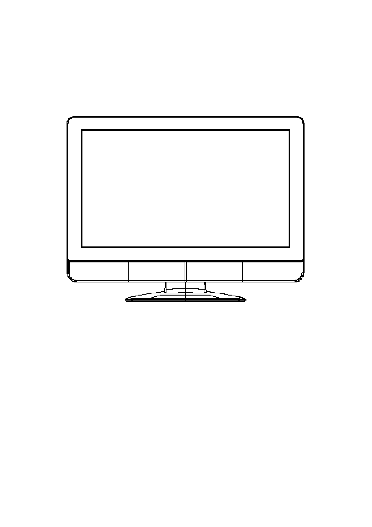
Product Name VIZIO VO370M
Panel RAKEN LC370WUE_SBA1
Display Pixels 1920 (H) x 1080 (V) pixels
Active Display Area (mm) 819.36 (H) x 460.89 (V)
Aspect Ratio 16:9
Color Depth 8 bit(D)
2
)
Luminance of White (cd/m
(Typical, Panel Spec.)
Contrast Ratio LC370WUE_SBA1 1400:1
TV system NTSC/ATSC/QAM
LC370WUE_SBA1 500
PC Inputs 15pins D-Sub
Video Inputs 1x RF (Combo, F Connector for internal NTSC/ATSC/QAM
Tuner)
3x HDMI with HDCP plus Stereo Analog Audio
2x Component YPbPr plus Stereo Audio
2x Composite Video plus Stereo Audio
1x S-Video plus Stereo Audio
1x Analog RGB plus Stereo Audio
USB firmware update
Audio Inputs 1x Stereo Audio (RCA)
1x PC mini jack
Audio Outputs 1x SPDIF Digital Audio (Optical)
1x Stereo Analog Audio
Service Port USB service port
Audio Speaker 10W X 2
Power Input 100~240Vac at 50/60 Hz
Power Consumption
EDID version VGA – 1.3
Preset Modes Primary 1920 (H) x 1080 (V) @ 60Hz.
CONFIDENTIAL – DO NOT COPY
Max 178 /Avg. 126 W, Standby <0.5 W
HDMI – 1.3
Page 2-1
File No. SG-0299
Page 6
Optical Characteristics
RAKEN Panel
Item Specification
Supplier RAKEN
Panel LC370WUE_SBA1
Display Pixels (H x V) 1920 x 1080
Active Display Area
(H x V, mm)
Color Depth 8bit(D)
Pixel Pitch (H x V, mm) 0.42675mm x 0.42675mmxRGB
Luminance of white (cd/m2)
(Center of Screen, Typical)
Contrast Ratio 1400:1
White
Color
Red
coordinate
(typical)
Green
±0.030
Blue
x 0.279
y 0.292
x 0.639
y 0.334
x 0.289
y 0.606
x 0.145
y 0.065
819.36 (H) x 460.89 (V)
500
Remark: All characteristics are measured at least 30 minutes later after power-on in the
normal ambient temperature
2. POWER SUPPLY
a. Input voltage: 100~240Vac, 50/60Hz
b. Input current: 3A (at AC 90V/60Hz)
c. Inrush current: 100A at Vac=100V
d. Power consumption: 178 W MAX/ 126 W AVG
e. Standby / Power off: <0.5 Watts. (at 115 Vac)
Mechanical and Packaging Specifications
CONFIDENTIAL – DO NOT COPY
File No. SG-0299
Page 2-2
Page 7
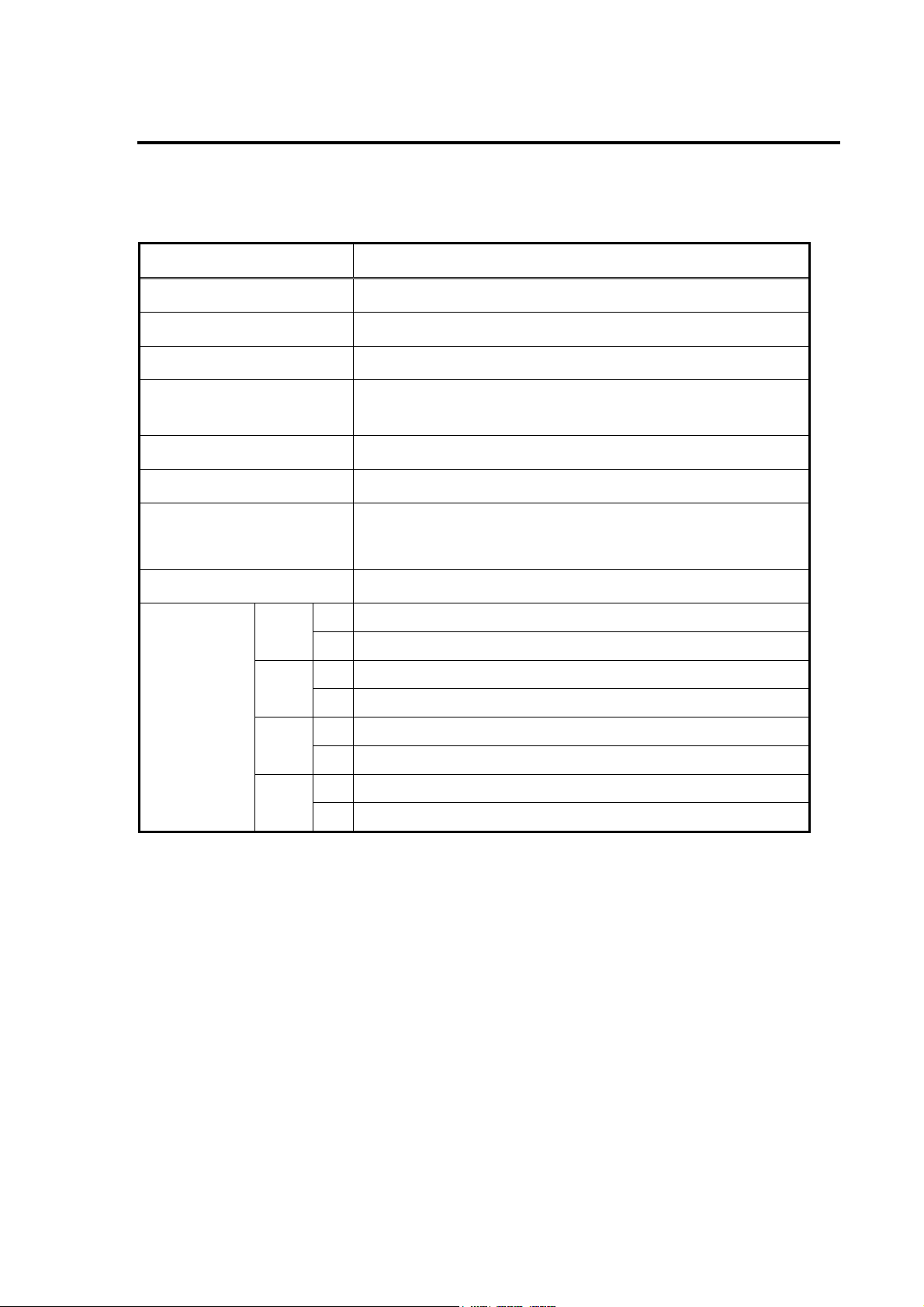
MECHANICAL SPECIFICATION
Gap allowance between bezel & panel surface
Horizontal Tilt
Panel disposition tolerance
Product balance
Gap ≦4.0
|A-B| ≦NONE
C,D,E,F >0
|G-H| ≦5 mm
(Unit: mm)
89°≦T≦91°
Tilt angle
up :-2° ~ -5°
Down : 13° ~ 18°
OUTLINE DIMENSION
Physical dimension
(Unit: mm)
Display Module Display Module + Base
Height 603.7 634.3
Width 919.9 919.9
Depth 98 218.2
CONFIDENTIAL – DO NOT COPY
Page 2-3
File No. SG-0299
Page 8
Weight
Material, color
Front bezel ABS(94-HB) Chocolate T52013
Rear cover ABS(94-5V) Black T52013
Base Ass’y ABS(94-HB) Chocolate T52012
a. Net (W/O Base): 12.6 ±1.0kg
b. Net (W/ Base): 13.1 ±1.0kg
c. Gross: 17.0±1.0kg
Part name Material Color
Wall-mounting
a. Screw size: M6* PITCH 1.0 mm
b. Screw Q'ty: 4 pcs
c. Mounting hole pitch: 400 (H), 200 (V) (mm)
PACKAGING SPECIFICATION
Packaged dimensions
a. Height 745.0 ±10 mm
b. Width 1060.0 ±10 mm
c. Depth 225.0 ±10 mm
Pallet Load
a. Sea A)15 units / pallet
b. Air A)NONE
Container Load
a. 40’ container 330 units (=15*22 Pallets)
b. 20’ container 100 units (=10*10 Pallets)
CONFIDENTIAL – DO NOT COPY
Page 2-4
File No. SG-0299
Page 9
ACCESSORIES
a. 1.8M HDMI Cable x 1
b. 1.8M Power Cord 110V UL/CSA Black x 1
c. VIZIO Universal Remote Control VUR8P x 1
d. User’s Manual x 1
e. Quick Start Guide x 1*
f. Registration card x 1
g. Service Brochure x 1*
h. AA batteries x 2
i. D size Polishing Cloth x 1
j. Safety Strap x 1
k. Product Warranty & Repair sheet x 1
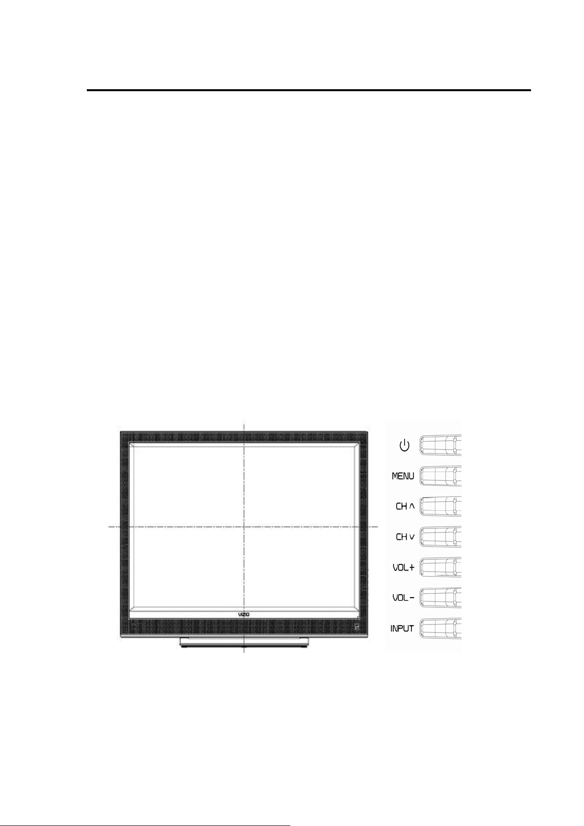
External Control Panel & Indicators
CONFIDENTIAL – DO NOT COPY
Page 2-5
File No. SG-0299
Page 10
3. LED INDICATOR DISPLAY ON THE FRONT
LED indicator Status Remark
Off AC power off By disconnecting the power cord
White Power on
Orange Standby
Becoming dimmer after lighting up a few
seconds
Becoming dimmer after lighting up a few
seconds
4. SPECIFICATION AND EXPLANATION OF USER CONTROL PANEL
ON THE SIDE
Buttons 1 2 3 4 5 6 7
Name
Standby/Power on
After AC on, by pressing Power button, LED indicator turns to white to indicate power
on. To turn off this device, press this button again.
(Power
MENU CH+ CH- VOL+ VOL- INPUT
symbol))
Menu Operation
Press MENU button to activate the OSD. Press this button again to exit.
Channel Selection
By operating the CH+ and CH- buttons, channel should be selected. At the time,
channel should increase with CH+ button and decrease with CH- button.
When the “MENU” is activated, it can be navigated up by CH+ button and down by
CH- button.
CONFIDENTIAL – DO NOT COPY
File No. SG-0299
Page 2-6
Page 11

Volume Adjustment
By operating the VOL+ and VOL-/ buttons, volume should be available to change
from minimum to maximum. At the time, volume should increase with VOL+ button
and decrease with VOL- button, and volume shift should be smooth.
When the “MENU” is activated, it can be navigated left by VOL+ button and right by
VOL-button.
Input Change
This button allows the user to cycle through the input sources in the following
sequence: TV, AV1(S-Video), AV2 (Video*), Component 1, Component 2, RGB,
HDMI 1, HDMI 2 and HDMI 3.
5. Speaker
Output 6Ω/10W (max) X2
6. ENVIRONMENT
Operating Temperature: 5℃~35℃ (Ambient)
Operating Humidity: Ta= 35 °C, 90%RH (Non-condensing)
Operating Altitude: 0~14,000 feet (Non-Operating)
7. WEIGHT (Physical weight)
Net (Without Base): 12.6 ±1.0kg
Net (With Base): 13.1 ±1.0kg
Gross: 17.0±1.0kg
CONFIDENTIAL – DO NOT COPY
Page 2-7
File No. SG-0299
Page 12

Chapter 3 On Screen Display
Main unit button
Power
MENU
CH ▲
CH ▼
VOL ▲
VOL▼
Input (TV Source on Screen Display)
AV, Component
A. PICTURE ADJUST:
a. Picture Mode (Custom/Standard/
Movie/Game/Vivid/Football/Golf/Basketb
all Baseball)
b. Backlight (0~100)
c. Brightness (0~100)
d. Contrast (0~100)
e. Color (0~100)
f. Tint (-32~+32)
g. Sharpness (0~7)
h. Advance Video
Noise Reduction/Color
Enhancement/Advanced Adaptive
CONFIDENTIAL – DO NOT COPY
Luma/Backlight Control/Color
Temperature/Film Mode
i.Rest Picture Mode
Page 3-1
File No. SG-0299
Page 13

B. AUDIO ADJUST:
a. Audio Mode (Flat/Rock/Pop/Classic/Jazz)
b.Equalizer (120Hz0/500Hz/1.5KHz/
5KHz/10KHz)
c.Balance(-50~0~50)
d.SRS TSHD(On/OFF)
e.Digital Audio Out (PCM/Off/Dolby Digital)
f.Speakers(On/Off)
g.Analog Audio Out (Fixed/Variable)
h.Lip Sync(0~5)
i.Reset Audio Mode
C. SETUP:
a. Language(English/Espanol /Francais)
b. Sleep Timer (OFF/30MIN/60MIN/90MIN/
120MIN)
c. Wide(Zoom1)
d. Input
Naming(AV1/AV2/Component1/Compone
nt2/RGB/HDMI1/HDMI2/HDMI3)
e. CC (Off/CC1/CC2/CC3/CC4)
f. Parental(Password)
g. System Info
h. System Reset
(Setup Wizard/Reset All Setting)
CONFIDENTIAL – DO NOT COPY
Page 3-2
File No. SG-0299
Page 14

D. PARENTAL CONTROL:
a. Channel Block
b. US TV Rating
c. US Movie Rating
d. Canadian English Rating
e. Canadian French Rating
f. DTV Rating
g. Block Unrated TV (No/Yes)
h. Access Code Edit
HDMI
A. PICTURE ADJUST:
a. Picture Mode (Custom/Standard/
Movie/Game/Vivid/Football/Golf/Basketb
all Baseball)
b. Backlight (0~100)
c. Brightness (0~100)
d. Contrast (0~100)
e. Color (0~100)
f. Tint (-32~+32)
g. Sharpness (0~7)
h. Advance Video
Noise Reduction/Color
Enhancement/Advanced Adaptive
CONFIDENTIAL – DO NOT COPY
Luma/Backlight Control/
Color Temperature/Film Mode
i. Rest Picture Mode
Page 3-3
File No. SG-0299
Page 15

B. AUDIO ADJUST:
a. Audio Mode Flat/Rock/Pop/Classic/Jazz)
b.Equalizer(120Hz0/500Hz/
1.5KHz/5KHz/10KHz)
c.Balance(-50~0~50)
d.SRS TSHD(On/OFF)
e. Digital Audio Out (PCM/Off/Dolby Digital)
f.Speakers(On/Off)
g.Analog Audio Out (Fixed/Variable)
h.Lip Sync(0~5)
i.Reset Audio Mode
C. SETUP:
a. Language(English/Espanol /Francais/)
b. Sleep Timer (OFF/30MIN/60MIN/90MIN/
120MIN)
c. Wide(Zoom1)
d. Input
Naming(AV1/AV2/Component1/Compone
nt2/RGB/HDMI1/HDMI2/HDMI3)
e. System Info
f. System Reset
(Setup Wizard/Reset All Setting)
CONFIDENTIAL – DO NOT COPY
Page 3-4
File No. SG-0299
Page 16

D. ADVANCED VIDEO:
a. Noise Reduction
(OFF/Low/Medium/Strong)
b. Color
Enhancement(OFF/Normal/Rich
Color/(Green/Flesh)/(Green/Blue))
c. Advance Adaptive
LUMA(OFF/Low/Medium/Strong/Exte
nd)
d. Backlight Control(OFF/DCR/OPC)
e. Color Temperature
(Color Temperature
(Color temputer/Normal//Custom)
RGB MODE
/Red(0~255)/Green(0~255)/Blue(0~255)
f.Film Mode(Auto/OFF)
A. PICTURE ADJUST:
a. Auto Adjust
b. Backlight (0~100)
c. Brightness (0~100)
d. Contrast (0~100)
e. Color Temperature( Color
Temperature(9300/6500/CUSTOM)/Red(
0~255)/Green(0~255)/Blue(0~255))
f. H-Size (0~255)
g. H. Position (0~100)
h. V. Position (0~100)
CONFIDENTIAL – DO NOT COPY
i. Fine Tune (0~31)
Page 3-5
File No. SG-0299
Page 17

B. AUDIO ADJUST:
a. Audio Mode (Flat/Rock/Pop/Classic/Jazz)
b. Equalizer(120Hz0/500Hz/1.5KHz/5KHz/1
0KHz)
c. Balance(-50~0~50)
d. SRS TSHD(On/Off)
e. Digital Audio Out (PCM/Off/Dolby Digital)
f. Speakers(On/Off)
g. Analog Audio Out(Fixed/Variable)
h. Lip Sync(0~5)
i. Reset Audio Mode
C. SETUP:
a. Language(English/Espanol /Francais/)
b. Sleep Timer (OFF/30MIN/60MIN/90MIN/
120MIN)
c. Wide(Full/Stretch)
d.Input Naming
(AV1/AV2/Component1/Component2/
RGB/HDMI1/HDMI2/HDMI3)
e.System Info
f.System Reset
(Setup Wizard/Reset All Setting)
CONFIDENTIAL – DO NOT COPY
Page 3-6
File No. SG-0299
Page 18

(1) TV&DTV MODE
A. PICTURE ADJUST:(ATV & DTV)
a. Picture Mode (Custom/Standard/
Movie/Game/Vivid/Football/Golf/Basketb
all Baseball)
b. Backlight (0~100)
c. Brightness (0~100)
d. Contrast (0~100)
e. Color (0~100)
f. Tint (-32~+32)
g. Sharpness (0~7)
h. Advance Video
Noise Reduction/Color
Enhancement/Advanced Adaptive
Luma/Backlight Control/
Color Temperature/Film Mode
i. Reset Picture Mode
B. AUDIO ADJUST:(ATV & DTV)
a. Audio Mode
(Flat/Rock/Pop/Classic/Jazz)
b. Equalizer(120Hz0/500Hz/1.5KHz/5K
Hz/10KHz)
c. Balance(-50~0~50)
d. SRS TSHD(Off/On)
e. Digital Audio Out (PCM/Off/Dolby
Digital)
f. Speakers(On/Off)
g. Analog Audio Out(Fixed/Variable)
h. Lip Sync(0~5)
i. Reset Audio Mode
CONFIDENTIAL – DO NOT COPY
Page 3-7
File No. SG-0299
Page 19

C. TV: (ATV & DTV)
a. Tuner Mode (Cable/Antenna)
b. Auto Search
c. Partial Channel Search
d. Skip Channel
e. MTS(Stereo/SAP/Mono) (ATV )
MTS ((1/2 English 5.)/ (2/2 Spanish
st))(DTV)
f. Time Zone (Eastern/Indiana/Central/
Mountain/Arizona/Newfoundland/Pacific/
Alaska/Hawaii/Atlantic)
g. Daylight Saving (On/Off)
h. Channel info
D. SETUP: (ATV only)
a. Language(English/Espanol /Francais)
b. Sleep Timer (OFF/30MIN/60MIN/90MIN/
120MIN)
c. Wide(Normal/Panoramic/Zoom1/Zoom2)
d. Input Naming
(AV1/AV2/Component1/Component2/
RGB/HDMI1/HDMI2/HDMI3)
e. CC (CC/Digital CC Style)
f. H/V Position(H. Position/V. Position/
H-Size/ V-Size)
g. Parental
h. System Info
i. System Reset
(Setup Wizard/Reset All Setting)
CONFIDENTIAL – DO NOT COPY
Page 3-8
File No. SG-0299
Page 20

E. SETUP: (DTV only)
a. Language(English/Espanol /Francais/)
b. Sleep Timer (OFF/30MIN/60MIN/90MIN/
120MIN)
c. Wide(Zoom1/Stretch)
d. Input
Naming(AV1/AV2/COMPONENT1/CO
MPONNT2/RGB/HDMI1/HDMI2)
e. CC (CC/Digital CC Style)
f. Parental
g. System Info
h. System Setup
(Setup Wizard/Reset All Setting)
F. PARENTAL:(ATV & DTV)
a. Channel Block
b. US TV Rating
c. US Movie Rating
d. Canadian English Rating
e. Canadian French Rating
f. DTV Rating
g. Block Unrated TV
h. Access Code Edit
CONFIDENTIAL – DO NOT COPY
Page 3-9
File No. SG-0299
Page 21

G. ADVANCED VIDEO:(ATV & DTV)
a. Noise Reduction
(Off/Low/Medium/Strong)
b. Color Enhancement (Off/Normal/Rich
Color/(Green/Flesh)/(Green/Blue))
c. Advance Adaptive LUMA
(Off/Low/Medium/Strong/Extend)
d. Backlight Control(DCR/OPC/Off)
e. Color Temperature(Color
Temperature/Red
/Green/Blue)
f.Film Mode(Auto/Off)
H. CC
a. CC (Off/CC1/2/3/4/Service1/2/3/4/5/6)
b. Digital CC Style
(Caption Style/Font Size/Font Color/Font
Opacity/Background Color/Background
Opacity/Window Color/Window Opacity)
CONFIDENTIAL – DO NOT COPY
Page 3-10
File No. SG-0299
Page 22

Chapter 9 Trouble shooting
MONITOR DISPLAY NOTHING (PC MODE)
Start
LED is lighted
N0
LED is White?
Yes
N0
N0
1. Is Power Core Ready?
2. Is J7-Pin1 5V ready?
J7-Pin 2, 3 Voltage normal?
3. Check Logo LED Circuit whether is normal?
4. Is Main BD -J4 +5VSB, +12 ready?
5. Is U1 (+5V) working ok?
6. Is DC to DC Regulator normal?
1. Check Key Pad or Remote control is OK?
2. Check U12-Pin 91 whether it’s voltage level is low?
3. Check Logo LED Circuit whether is normal?
Yes
N0
Is backlight on?
1. Is J8, PIN6, 8, 10, 12 that voltage 12V ready?
2. Check J8, PIN24, 26 PWM signal is OK?
3. Check J4, Pin14 whether it is high?
4. Check J4, Pin17 whether its voltage is 0~0.8V?
Yes
1. Video cable is OK?
Is Display
Normal?
Yes
N0
2. Is P1 video input signal normal?
3. Whether U12 input/output signal of video signal is
normal?
4. Check J8 video signal whether is normal.
5. Is LVDS Cable OK?
END
CONFIDENTIAL – DO NOT COPY
Page 9-1
File No. SG-0299
Page 23

(TV,
COMPOSITE, VIDEO) IS NOT DISPLAY CORRECTLY
Start
LED is lighted
N0
1. Is Power Core Ready?
2. Is J7-Pin1 5V ready?
J7-Pin 2, 3 Voltage normal?
3. Check Logo LED Circuit whether is normal?
4. Is Main BD -J4 +5VSB, +12 ready?
5. Is U1 (+5V) working ok?
6. Is DC to DC Regulator normal?
LED is White?
Yes
N0
N0
1. Check Key Pad or Remote control is OK?
2. Check U12-Pin 91 whether it’s voltage level is low?
3. Check Logo LED Circuit whether is normal?
Yes
N0
Is backlight on?
1. Is J8, PIN6, 8, 10, 12 that voltage 12V ready?
2. Check J8, PIN24, 26 PWM signal is OK?
3. Check J4, Pin14 whether it is high?
4. Check J4, Pin17 whether its voltage is 0~0.8V?
Yes
1. Video cable is OK?
2. Is P4, P3 (COMPOSITE INPUT), and U34 (or U24) video
input signal normal?
3. Whether U12 input/output signal of video signal is
normal?
4. Check J8 video signal whether is normal.
5. Is LVDS Cable OK?
Is Display
Normal?
N0
Yes
END
CONFIDENTIAL – DO NOT COPY
Page 9-2
File No. SG-0299
Page 24

(COMPONENT) IS NOT DISPLAY CORRECTLY
Start
LED is lighted
N0
1. Is Power Core Ready?
2. Is J7-Pin1 5V ready?
J7-Pin 2, 3 Voltage normal?
3. Check Logo LED Circuit whether is normal?
4. Is Main BD -J4 +5VSB, +12 ready?
5. Is U1 (+5V) working ok?
6. Is DC to DC Regulator normal?
LED is White?
Yes
N0
N0
1. Check Key Pad or Remote control is OK?
2. Check U12-Pin 91 whether it’s voltage level is low?
3. Check Logo LED Circuit whether is normal?
Yes
Is backlight on?
N0
1. Is J8, PIN6, 8, 10, 12 that voltage 12V ready?
2. Check J8, PIN24, 26 PWM signal is OK?
3. Check J4, Pin14 whether it is high?
4. Check J4, Pin17 whether its voltage is 0~0.8V?
Yes
1. Video cable is OK?
2. Is P2, P3 (COMPONENT INPUT) video input signal
normal?
3. Whether U12 input/output signal of video signal is
normal?
4. Check J8 video signal whether is normal.
5. Is LVDS Cable OK?
Is Display
Normal?
N0
Yes
END
CONFIDENTIAL – DO NOT COPY
Page 9-3
File No. SG-0299
Page 25

HDMI IS NOT DISPLAY CORRECTLY
Start
LED is lighted
N0
LED is White?
Yes
N0
N0
1. Is Power Core Ready?
2. Is J7-Pin1 5V ready?
J7-Pin 2, 3 Voltage normal?
3. Check Logo LED Circuit whether is normal?
4. Is Main BD -J4 +5VSB, +12 ready?
5. Is U1 (+5V) working ok?
6. Is DC to DC Regulator normal?
1. Check Key Pad or Remote control is OK?
2. Check U12-Pin 91 whether it’s voltage level is low?
3. Check Logo LED Circuit whether is normal?
Yes
N0
Is backlight on?
1. Is J8, PIN6, 8, 10, 12 that voltage 12V ready?
2. Check J8, PIN24, 26 PWM signal is OK?
3. Check J4, Pin14 whether it is high?
4. Check J4, Pin17 whether its voltage is 0~0.8V?
Is Display
Normal?
Yes
Yes
N0
1. Video cable is OK?
2. Is P7~9 video input signal normal?
3. Whether U12 input/output signal of video signal is
normal?
4. Check J8 video signal whether is normal.
5. Is LVDS Cable OK?
END
CONFIDENTIAL – DO NOT COPY
Page 9-4
File No. SG-0299
Page 26

TROUBLE OF DC-DC CONVERTER
Star t
Yes
J4 PIN10, 11, 12, U13 Pin2
Yes
J4 PIN 2, 3, 4
Yes
U1 pin 5 6 7 8
Yes
U2, U4, U7 pin2
Yes
U3 pin3, 4
Yes
U5 pin2
N0
The voltage is +5V
1. Check power board
2. Check power cable connection J4
N0
The voltage is +12V while power switch on
1. J4 connection good
2. Check power board
N0
The voltage is +5V while power switch on
1. Check U12 OPWRSB Pin
N0
The voltage is about +3.3V
N0
The voltage is about +1.3V
N0
The voltage is about +2.6V
Yes
U6 pin6, U8 pin2
Yes
U19 pin2
Yes
U9 pin2
Yes
U21 pin 5,6,7,8
Yes
END
N0
N0
N0
N0
The voltage is about +1.25V
The voltage is about +2.5V
The voltage is about +2.5V
The voltage is about +12V
CONFIDENTIAL – DO NOT COPY
Page 9-5
File No. SG-0299
Page 27

TROUBLE OF DDC READING
Start
Yes
N0
Analog DDC OK?
Yes
N0
HDMI DDC OK?
Yes
Support DDC1/2B
1. VGA cable ok?
2. Check signal (U22 to P1)
3. Check U22 Voltage
4. Is compliant protocol?
Support DDC1/2B
1. HDMI cable ok?
2. Check signal (U19 to P9)
3. Check signal (U31 to P7)
4. Check signal (U30 to P8)
5. Is compliant protocol?
END
CONFIDENTIAL – DO NOT COPY
Page 9-6
File No. SG-0299
Page 28

AUDIO FUNCTION IS NOT WORKING CORRECTLY
Start
Yes
Input signal good?
Output Source OK?
Check signal correct?
Check amplifier OK?
Yes
Yes
Yes
Yes
N0
N0
N0
N0
N0
1. Check Audio source
2. Check the player of source
1. Check Speaker or
Audio Output P11, P12 Audio
Signal
1. Check MT8380 Audio In/Out
2. U44 AUDIO In/Out
1. Check U33 Audio Signal
In/OUT
Yes
END
CONFIDENTIAL – DO NOT COPY
Page 9-7
File No. SG-0299
Page 29

Page 30

Page 31

 Loading...