


VIZIO VO32L HDTV10A User Manual
Table of Contents
Table of Contents
Table of ContentsTable of Contents
Chapter 1 Basic Controls and Connections
Chapter 1 Basic Controls and Connections ................................
Chapter 1 Basic Controls and ConnectionsChapter 1 Basic Controls and Connections
1.1 Front Panel..........................................................................................................................................................9
1.2 Side Panel Controls.............................................................................................................................................9
1.3 Rear Panel Connections ...................................................................................................................................10
1.4 Right-Side Panel Connection ............................................................................................................................11
1.5 VIZIO Remote Control.......................................................................................................................................12
1.5.1 Insertion of Batteries in the Remote Control ..............................................................................................14
1.5.2 Remote Control Range ..............................................................................................................................14
1.5.3 VIZIO Universal Remote Control Precautions ...........................................................................................14
Chapter 2 Connecting Equipment
Chapter 2 Connecting Equipment................................
Chapter 2 Connecting EquipmentChapter 2 Connecting Equipment
2.1 Which Video Connection Should I Use?............................................................................................................15
2.2 Connecting Coaxial (RF) ...................................................................................................................................16
2.2.1 Using Your Antenna or Digital Cable for DTV ............................................................................................16
2.2.2 Using the Antenna or Cable through your VCR .........................................................................................16
2.3 Connecting Your HDTV Set-Top Box ................................................................................................................17
2.3.1 Using HDMI Input ......................................................................................................................................17
2.3.2 Using Component Video............................................................................................................................19
2.4 Connecting Your Basic Set-Top Box .................................................................................................................20
2.4.1 Using Composite Video .............................................................................................................................20
2.4.2 Using Coax (RF) ........................................................................................................................................20
2.5 Connecting Your DVD Player ............................................................................................................................21
2.5.1 Using HDMI Input ......................................................................................................................................21
2.5.2 Using Component Video............................................................................................................................23
2.5.3 Using S-Video (AV1/S-VIDEO) ..................................................................................................................24
2.5.4 Using Composite (AV) Video Input ............................................................................................................24
2.6 Connecting Your VCR or Video Camera ..........................................................................................................25
2.7 Connecting an external Receiver/Amp ..............................................................................................................26
2.7.1 Optical Output of Audio received ...............................................................................................................27
2.8 Connecting a PC Computer ..............................................................................................................................28
2.8.1 Preset PC Resolutions...............................................................................................................................29
Chapter 3 Setting Up to Watch Television
Chapter 3 Setting Up to Watch Television ................................
Chapter 3 Setting Up to Watch TelevisionChapter 3 Setting Up to Watch Television
3.1 Basic LCD HDTV Start Up ................................................................................................................................30
3.2 Watching a TV Program ....................................................................................................................................35
3.3 Adjusting Basic HDTV Settings .........................................................................................................................36
3.4 Program Information..........................................................................................................................................37
3.5 Information on HDTV Status .............................................................................................................................37
Chapter 4 Advanced Adjustment of HDTV
Chapter 4 Advanced Adjustment of HDTV................................
Chapter 4 Advanced Adjustment of HDTVChapter 4 Advanced Adjustment of HDTV
4.1 Using the On Screen Display (OSD) .................................................................................................................38
4.2 DTV / TV Input Picture Adjustment....................................................................................................................39
4.2.1 Picture Mode .............................................................................................................................................39
4.2.2 Backlight ....................................................................................................................................................39
4.2.3 Brightness..................................................................................................................................................40
4.2.4 Contrast .....................................................................................................................................................40
4.2.5 Color ..........................................................................................................................................................40
4.2.6 Tint.............................................................................................................................................................40
4.2.7 Sharpness .................................................................................................................................................41
4.2.8 Advanced Video Features .........................................................................................................................41
4.2.9 Reset Picture Mode ...................................................................................................................................43
4.3 DTV / TV Input Audio Adjustment......................................................................................................................44
4.3.1 Audio Mode ...............................................................................................................................................44
4.3.2 Equalizer....................................................................................................................................................44
4.3.3 Balance......................................................................................................................................................45
4.3.4 Surround....................................................................................................................................................45
4.3.5 Digital Audio Out........................................................................................................................................45
4.3.6 Speakers ...................................................................................................................................................45
4.3.7 Audio Out...................................................................................................................................................45
4.3.8 Lip Sync.....................................................................................................................................................46
4.3.9 Reset Audio Mode .....................................................................................................................................46
4.4 DTV / TV Tuner Setup.......................................................................................................................................47
4.4.1 Tuner Mode ...............................................................................................................................................47
................................................................
................................................................
................................................................
................................................................
.................................................
................................................................
................................................................
................................................................
................................................................
................................................................
.................................... 9999
................................................................
................. 15
..................................
....................................30
................................................................
..................................
................................................................
15
1515
30
3030
..38
38
....
3838
Version 4/1/2008 7
www.VIZIO.com

VIZIO VO32L HDTV10A User Manual
4.4.2 Auto Search...............................................................................................................................................47
4.4.3 Partial Channel Search..............................................................................................................................48
4.4.4 Skip Channel .............................................................................................................................................48
4.4.5 MTS ...........................................................................................................................................................48
4.4.6 Time Zone .................................................................................................................................................48
4.4.7 Daylight Saving..........................................................................................................................................49
4.5 DTV / TV Input Setup ........................................................................................................................................49
4.5.1 Language...................................................................................................................................................49
4.5.2 PIP (Picture-in-Picture) ..............................................................................................................................49
4.5.3 Sleep Timer ...............................................................................................................................................51
4.5.4 Wide ..........................................................................................................................................................51
4.5.5 Input Naming .............................................................................................................................................52
4.5.6 CC (Closed Caption)..................................................................................................................................53
4.5.7 H/V Position...............................................................................................................................................54
4.5.8 DTV / TV Input Parental Control ................................................................................................................55
4.5.9 Channel Block ...........................................................................................................................................55
4.5.10 US TV Rating...........................................................................................................................................56
4.5.11 US Movie Rating (For US) .......................................................................................................................57
4.5.12 Canadian English Rating .........................................................................................................................57
4.5.13 Canadian French Rating..........................................................................................................................58
4.5.14 DTV Rating ..............................................................................................................................................58
4.5.15 Blocked Unrated Programming................................................................................................................59
4.5.16 Change the Password .............................................................................................................................59
4.5.17 Reset All Settings ....................................................................................................................................60
4.6 HDMI Input Picture Adjustment .........................................................................................................................61
4.7 HDMI Input Audio Adjustment ...........................................................................................................................61
4.8 HDMI Input Setup..............................................................................................................................................61
4.9 Video Input Picture Adjustment .........................................................................................................................62
4.10 Video Input Audio Adjustment .........................................................................................................................62
4.11 Video Input Setup............................................................................................................................................62
4.12 Video Input Parental Control ...........................................................................................................................64
4.13 PC Input Picture Adjustment ...........................................................................................................................64
4.13.1 Auto Adjust ..............................................................................................................................................64
4.13.2 Backlight ..................................................................................................................................................64
4.13.3 Brightness................................................................................................................................................65
4.13.4 Contrast ...................................................................................................................................................65
4.13.5 Color Temperature...................................................................................................................................65
4.13.6 H-SIZE.....................................................................................................................................................66
4.13.7 H. Position ...............................................................................................................................................66
4.13.8 V. Position ...............................................................................................................................................66
4.13.9 Fine Tune ................................................................................................................................................67
4.14 PC Input Audio Adjustment .............................................................................................................................67
4.15 PC Input Setup ................................................................................................................................................67
4.16 Understanding Viewing Features ....................................................................................................................68
4.16.1 Viewing Modes ........................................................................................................................................68
Chapter 5 Maintenance and Troubleshooting
Chapter 5 Maintenance and Troubleshooting................................
Chapter 5 Maintenance and TroubleshootingChapter 5 Maintenance and Troubleshooting
5.1 Maintenance......................................................................................................................................................69
5.2 Troubleshooting Guide ......................................................................................................................................69
5.3 Telephone & Technical Support ........................................................................................................................71
5.4 Compliance .......................................................................................................................................................72
5.5 FCC Class B Radio Interference Statement ......................................................................................................72
Chapter 6 Miscellaneous Information
Chapter 6 Miscellaneous Information ................................
Chapter 6 Miscellaneous InformationChapter 6 Miscellaneous Information
6.1 Specifications ....................................................................................................................................................73
6.2 Glossary – Standard Definitions ........................................................................................................................74
6.3 Index .................................................................................................................................................................75
................................................................
................................................................
............................................................
................................................................
..........................................
................................................................
............................69
........................................................
.......... 73
....................
69
6969
73
7373
Version 4/1/2008 8
www.VIZIO.com
VIZIO VO32L HDTV10A User Manual
Chapter 1
Chapter 1 Basic Controls and Connections
Chapter 1Chapter 1
1.1
1.1 Front Panel
1.11.1
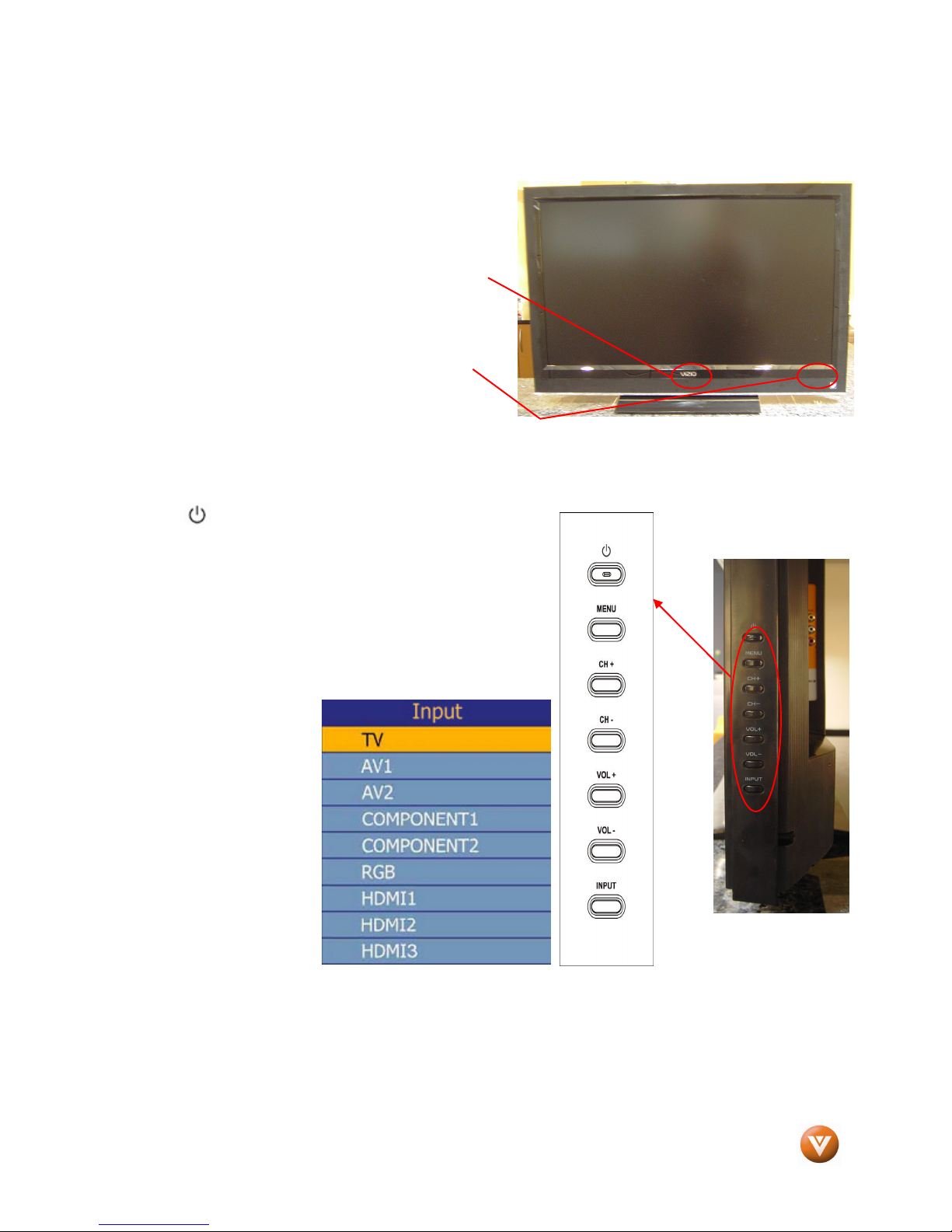
POWER ‘VIZIO’ LIGHT– The VIZIO name lights white
when powered on and orange when powered off.
REMOTE CONTROL SENSOR – This is the window
through which all of the remote control signals pass to
the sensor. Point the remote control directly at this
window for the best response to the remote signal.
1.2
1.2 Side Panel Controls
1.21.2
POWER ( ) – Switch the VO32L HDTV10A on by pressing
the button once. Press the button again to turn the VO32L
HDTV10A off.
MENU – This button activates the On Screen Display (OSD).
If a sub-menu is active, pressing this button will return to the
previous menu level.
CH + / - – Use these buttons to step up or down the TV
channels. While the OSD is
active, these buttons
function as up and down
controls in the OSD menus.
VOL + / - – Use these
buttons to increase or
decrease to the speaker
volume. While the OSD is
active, these buttons
function as left and right
controls in the OSD menus.
INPUT (ENTER) –
Repeated pressing of this
buttons steps through the
input sources in the following sequence: TV, AV1/S-Video, AV2, Component1, Component2, RGB, HDMI
1, HDMI 2 and HDMI 3. Once you have stepped through the entire sequence, you will return to the
beginning.
Additionally, when the OSD is active, this button confirms the menu function to be adjusted. When the
OSD is not active, pressing this button will display the current input mode.
Front Panel
Front PanelFront Panel
Side Panel Controls
Side Panel ControlsSide Panel Controls
Basic Controls and Connections
Basic Controls and Connections Basic Controls and Connections
Version 4/1/2008 9
www.VIZIO.com
VIZIO VO32L HDTV10A User Manual
1.3
1.3 Rear Panel Connections
1.31.3
Rear Panel Connections
Rear Panel ConnectionsRear Panel Connections
1
2
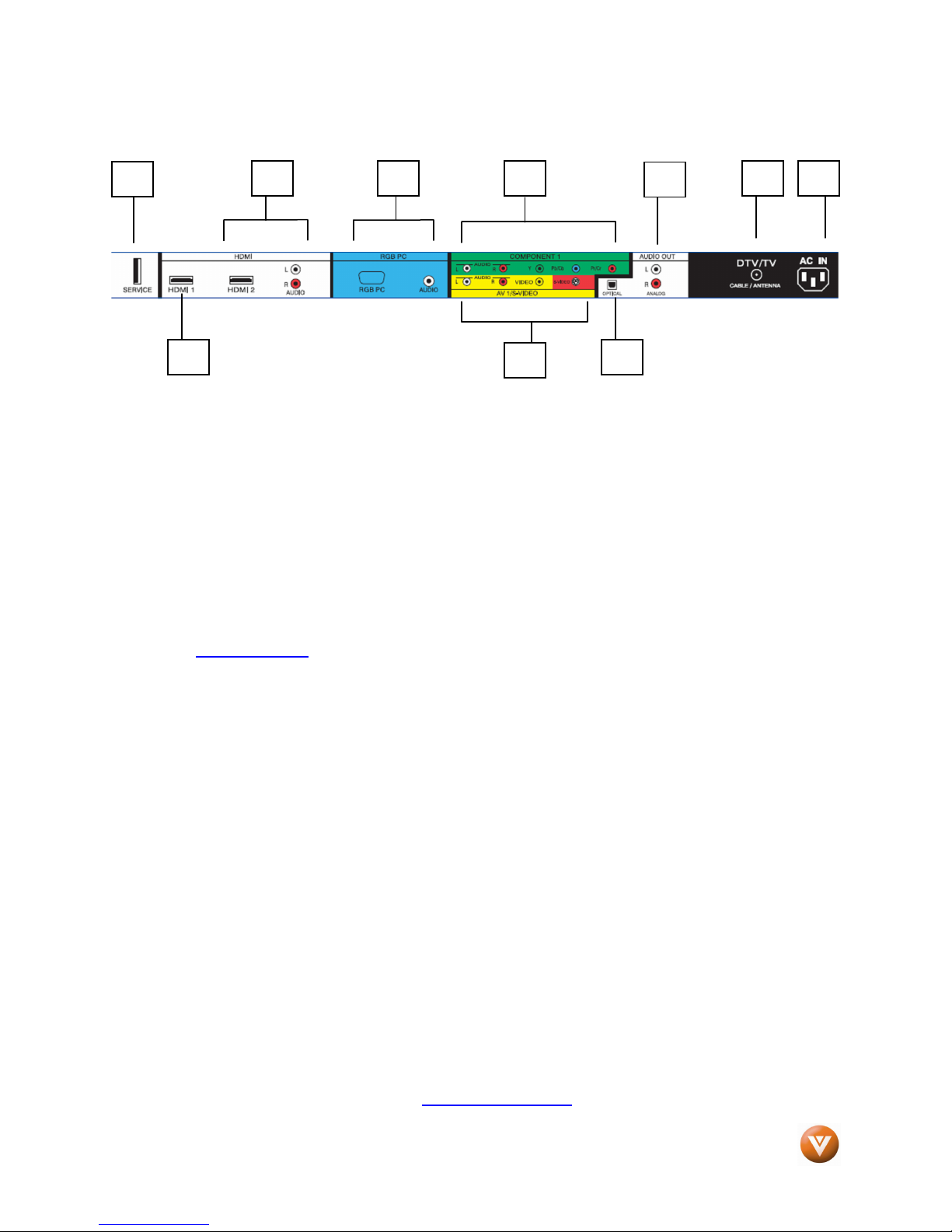
1. SERVICE – This custom communication port is for factory service only. Use of this input for
any purpose other than factory authorized service will void the manufacturer’s
warranty of this equipment.
2. HDMI 1 – Connect the primary source for digital video such as a DVD multimedia player or
set top box through this all digital connector. The white color band on the rear of the TV
indicates this connection.
3. HDMI 2 – Connect a secondary source for digital video such as a DVD multimedia player or
set top box through this all digital connector. The white color band on the rear of the TV
indicates this connection. For users who want to connect to a DVI enabled device, use a
DVI-HDMI cable and connect the Analog Audio output of the device to the L+R AUDIO here. .
Your VIZIO Certified HDMI and HDMI-DVI cables are available for purchase from
www.VIZIO.com or by calling 888-VIZIOCE (888-849-4623).
4. RGB PC – Connect the video and audio from a computer here. The blue color band on the
rear of the TV indicates this connection. A 1/8” plug stereo cable is needed to connect the
audio out from the computer to the connector in the rear of the TV for audio from computer.
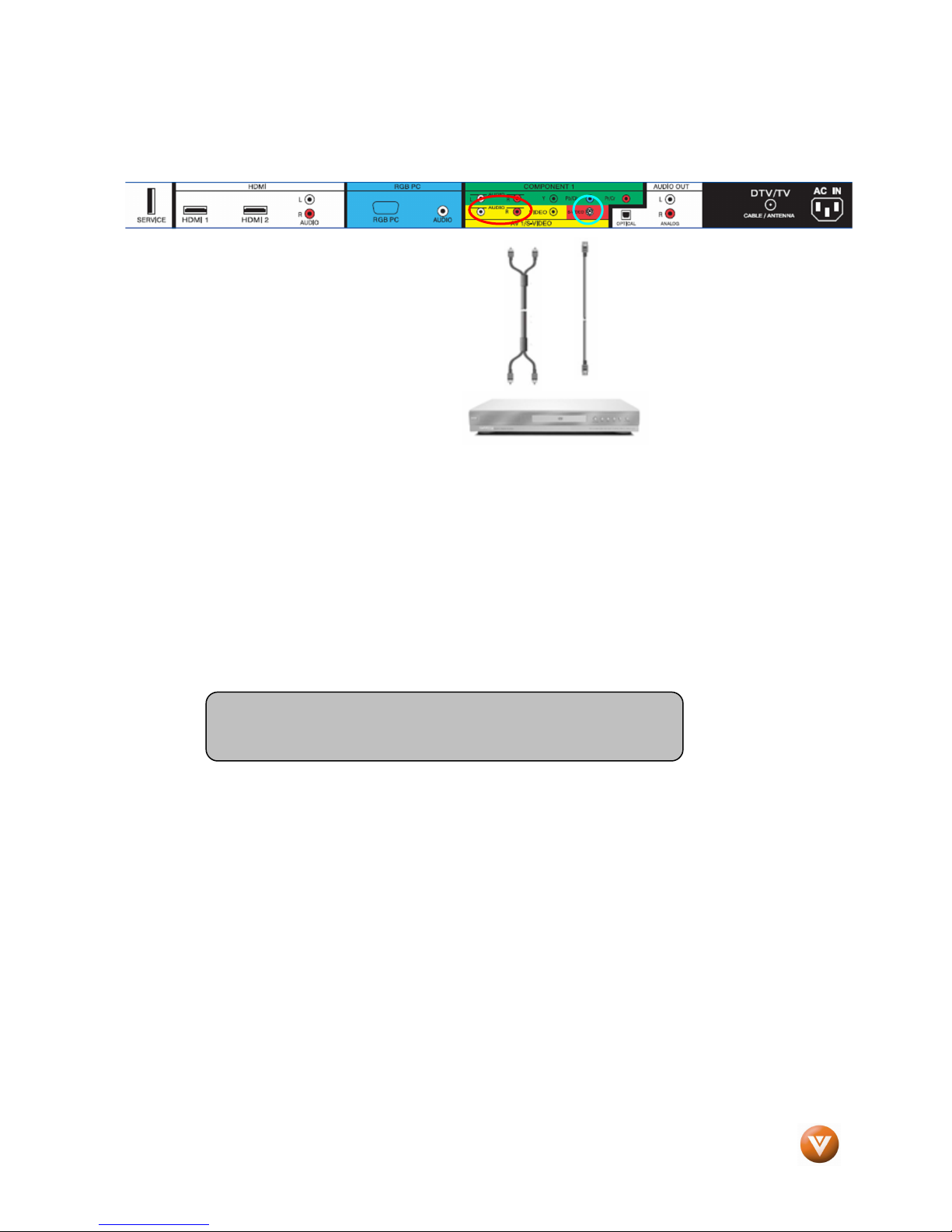
5. COMPONENT1 (YPb/CbPr/Cr with Audio L/R) – Connect the source for component video
devices such as a DVD Player or set top box here. From left to right, use white for left audio
and red for right audio inputs, green for Y, blue for Pb (or Cb) and red for Pr (or Cr). The
green color band on the rear of the TV indicates this connection.
6. AV1/S-VIDEO IN – Connect the primary source for composite video devices, such as a VCR
or video game. Use the white and red connectors to connect the external audio from the
same source, then use the S-Video or yellow connector to connect the external video from
the same source. The S-Video, if connected, will take priority over AV RCA (yellow)
connector. The yellow color band on the rear of the TV indicates this connection.
7. OPTICAL DIGITAL AUDIO OUT – When a digital audio signal is associated with an input
which is selected for viewing, the digital audio associated with digital programming will be
available on this SPDIF Optical connector for connection to your home theatre system. The
white color band on the rear of the TV indicates this connection.
8. ANALOG AUDIO OUT – Connect the audio from the LCD HDTV to an external device, such
as a home theater system, external amplifier or stereo. Speakers cannot be connected
directly to here. The white color band on the rear of the TV indicates this connection.
9. DTV – Connect to an antenna or digital cable (out-of-the-wall, not from Cable Box) for Digital
TV.*
10. AC IN – Plug-in the supplied AC Power Cord here.
* For digital TV stations in your area visit www.antennaweb.org.
3 9
4
5
6
8
7
10
Version 4/1/2008 10
www.VIZIO.com
1.4
1.4 Right
1.41.4
Right----Side Panel Connection
RightRight
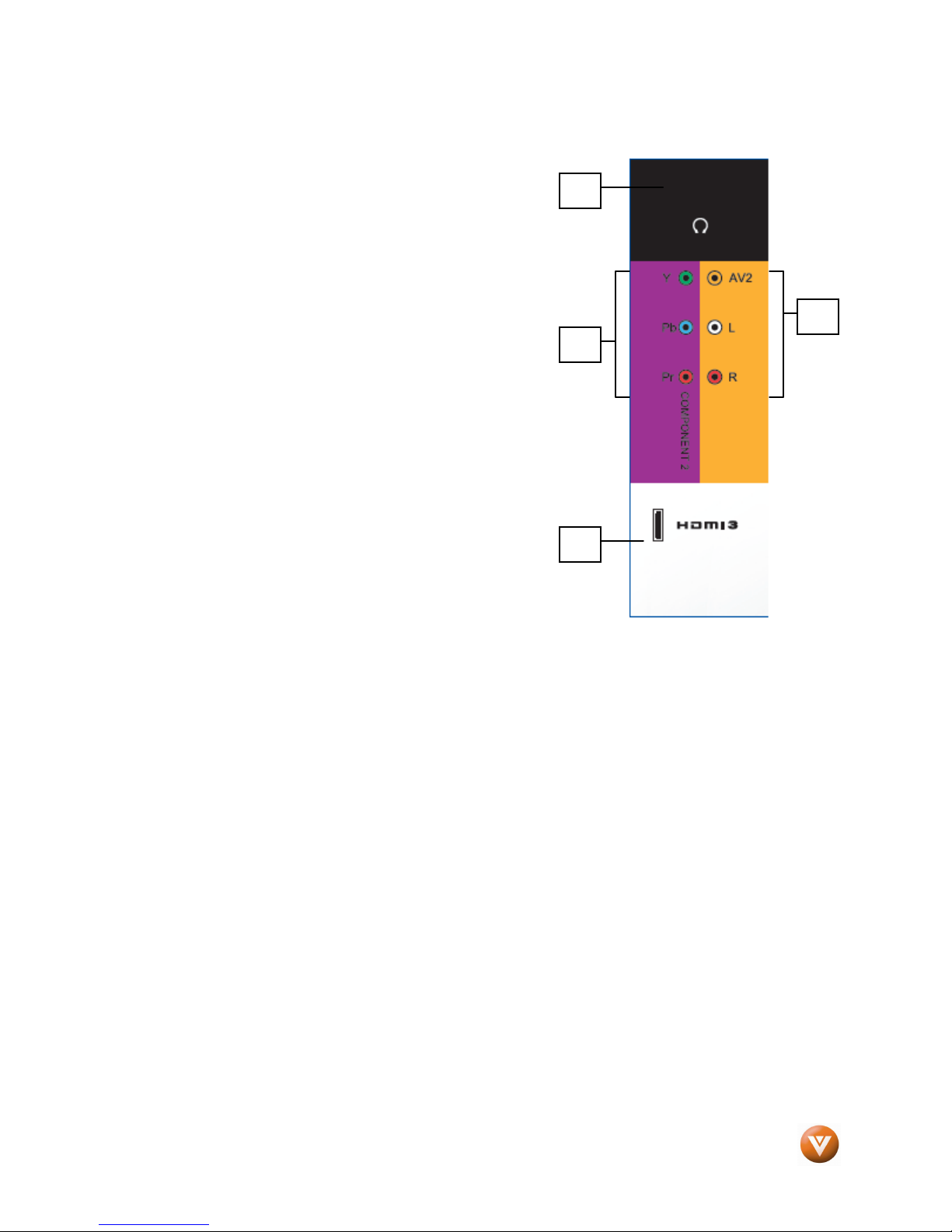
1. HEADPHONE – Connect your headphone here for
personalized listening without disturbing others.
2. AV2 – Connect the secondary source for composite video
devices, such as a VCR or video game. Use the white and red
connectors to connect the external audio from the same
source, then use the yellow connector to connect the external
video from the same source. The orange color band on the side
of the TV indicates this connection. Note: The red and white
audio connectors are shared between AV2 and
COMPONENT2.
3. COMPONENT2 (YPb/CbPr/Cr with Audio L/R) - Connect the
source for component video devices such as a DVD Player or
set top box here. From top to bottom, left to right, use green for
Y, blue for Pb (or Cb), red for Pr (or Cr), then connect white for
left audio and red for right audio inputs under the orange band.
The purple color band on the side of the TV indicates this
connection. Note: The red and white audio connectors are
shared between AV2 and COMPONENT2.
4. HDMI 3 - Connect the third source for digital video
such as a DVD multimedia player or set top box
through this all digital connector. The white color band
on the side of the TV indicates this connection.
Side Panel Connection
Side Panel ConnectionSide Panel Connection
VIZIO VO32L HDTV10A User Manual
1
2
3
4
Version 4/1/2008 11
www.VIZIO.com
VIZIO VO32L HDTV10A User Manual
1.5
1.5 VIZIO Remote Control
1.51.5
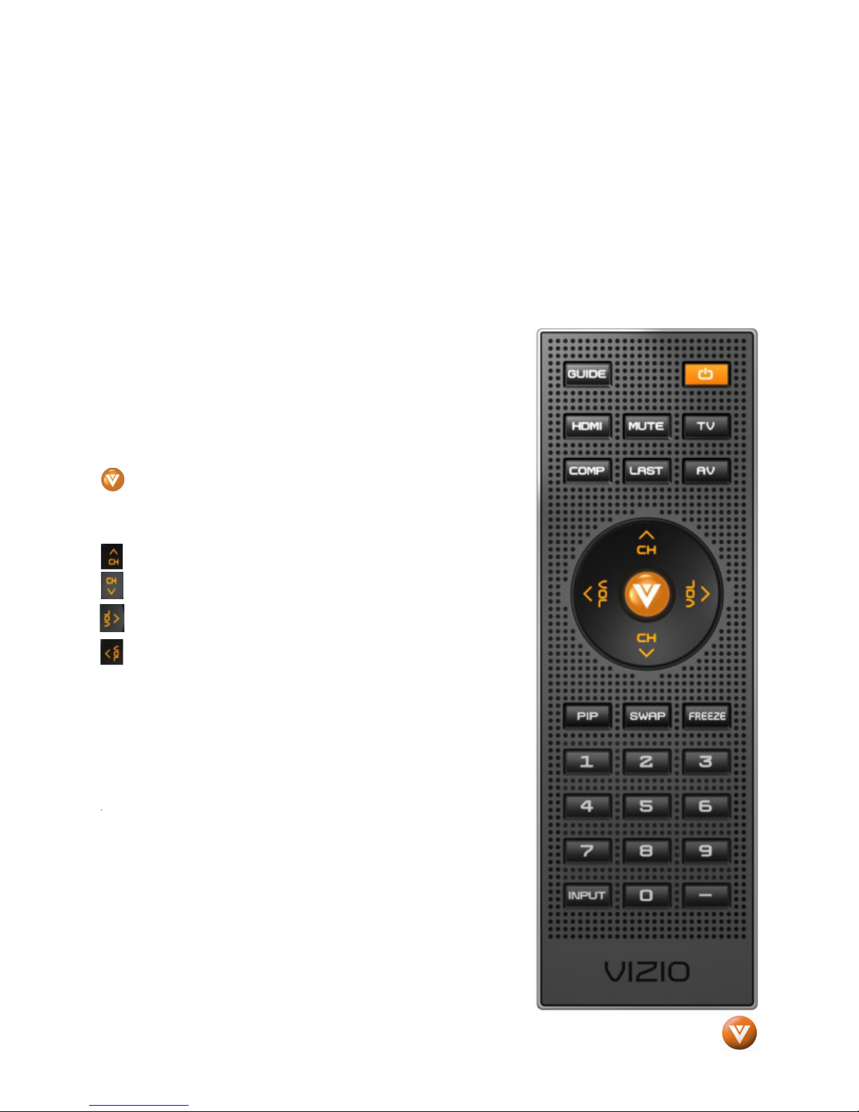
GUIDE – This button displays program information. Press this button once when in TV mode and the
information of the program being viewed is shown. Press it a second time and the Electronic
Programming Guide will appear in the screen. In any other mode when this button is pressed, the screen
will display the selected input plus the definition of the signal; i.e. HDMI 720p, HDMI 1080i, etc.
POWER – Press this button to turn the TV on from the Standby mode. Press it again to return to the
Standby mode.
HDMI – Press this button to select the HDMI input.
MUTE – This button turns the sound on and off.
TV – Press this button to select TV.
COMPONENT – Press this button to select the Component
(YPbPr) input.
LAST – This button recalls the previously viewed channel. If the
On-Screen Display (OSD) menu is being used, this button will allow
you to get back to previous menu screen or out to your program
when you press it repeatedly.
AV – Press this button to select AV (either Composite or S-Video)
input.
(MENU) – Use this button for the On-Screen Display (OSD)
menu. When it is used within a menu selection, the
help you to make the selection of the feature to be adjusted after it
has been highlighted.
VIZIO Remote Control
VIZIO Remote ControlVIZIO Remote Control
V
ball key will
-These labeled buttons are used to navigate the OSD menu.
When navigating the OSD menu, the arrows control the
direction up and down or left and right. They will also be used
as value settings when the slide bar is shown on the screen
and option settings to turn a feature off or on. During regular
TV watching these keys will provide us with the control
functions of Volume (up or down) and Channel (up or down).
Channel up or down will not function when a cable box or satellite
receiver is being used as the source of the signal.
PIP – Use this button to activate the Picture-in-Picture mode.
SWAP – Used to swap the inputs from the main screen and the
sub-screen while in PIP mode.
FREEZE – Press this button to “freeze-frame” the current screen.
Press this button again to continue playing.
hen
NUMBER BUTTON PAD – Use these buttons to select a channel
or enter a password.
Version 4/1/2008 12
www.VIZIO.com
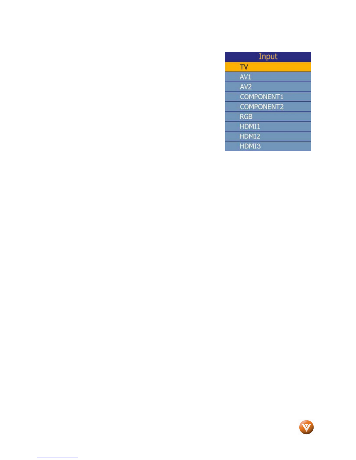
INPUT – This button allows the user to cycle through the inputs.
Repeatedly pressing of this button will step you through the input
sources in the following sequence: TV, AV1/S-VIDEO, AV2,
Component 1, Component 2, RGB, HDMI 1, HDMI 2 and HDMI 3.
Once you have stepped through the entire sequence, you will return
to the beginning.
- (DASH) – When selecting a digital channel directly use this button
for the separation of main and sub-channels. For example, channel
28-2 would be selected by the button sequence 2 8 ENTER 2.
VIZIO VO32L HDTV10A User Manual
Version 4/1/2008 13
www.VIZIO.com
VIZIO VO32L HDTV10A User Manual
1.5.1
1.5.1 Insertion of Batteries in the Remote Control
1.5.11.5.1
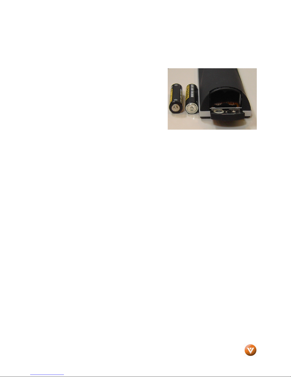
Insert two AA batteries into the remote control. Make sure that you match the (+) and (-) symbols on the
batteries with the (+) and (-) symbols inside the battery compartment. Re-attach the battery cover.
Precautionary Tips for Inserting the Batteries:
Only use the specified AA batteries.
Do not mix new and old batteries. This may result in
cracking or leakage that may pose a fire risk or lead to
personal injury.
Inserting the batteries incorrectly may also result in cracking
or leakage that may pose a fire risk or lead to personal injury.
Dispose of the batteries in accordance with local laws and
regulations.
Keep the batteries away from children and pets.
1.5.2
1.5.2 Remote Control Range
1.5.21.5.2
Point the remote control at the remote control sensor to transmit the commands.
Do not place any obstacles between the remote control and the receiver window.
The effective range of the remote control is approximately 30 feet (10 meters) from the front of the
receiver window, 30° to the left and right, 20° up and down.
Insertion of Batteries in the Remote Control
Insertion of Batteries in the Remote ControlInsertion of Batteries in the Remote Control
Remote Control Range
Remote Control RangeRemote Control Range
1.5.3
1.5.3 VIZIO Universal Remote Control
1.5.31.5.3
The remote control should be kept dry and away from heat sources. Avoid humidity.
If the TV responds erratically to the remote control or does not respond at all, check the batteries. If the
batteries are low or exhausted, replace them with fresh batteries.
When not using the remote control for a long period of time, remove the batteries.
Do not take the batteries apart, heat them, or throw them into a fire.
Do not subject the remote control to undue physical stress, such as striking or dropping it.
Do not attempt to clean the remote control with a volatile solvent. Wipe it with a clean, damp cloth.
VIZIO Universal Remote Control Precautions
VIZIO Universal Remote ControlVIZIO Universal Remote Control
Precautions
Precautions Precautions
Version 4/1/2008 14
www.VIZIO.com
VIZIO VO32L HDTV10A User Manual
Chapter 2
Chapter 2 Connecting Equipment
Chapter 2Chapter 2
2.1
2.1 Which Video Connection Should I Use
2.12.1
The VIZIO VO32L HDTV10A has six different ways to connect your video equipment from a basic
connection to the most advanced for digital displays.
Quality (type)
Which Video Connection Should I Use????
Which Video Connection Should I UseWhich Video Connection Should I Use
Connection
Connecting Equipment
Connecting Equipment Connecting Equipment
Rear
Connector
Panel
Color
Codes
Description
Best
(digital)
Best
(digital)
- - - - - - - - - - - Good
(analog)
Best
(analog)
Better
(analog)
White
Black
Blue
Green
and
Purple
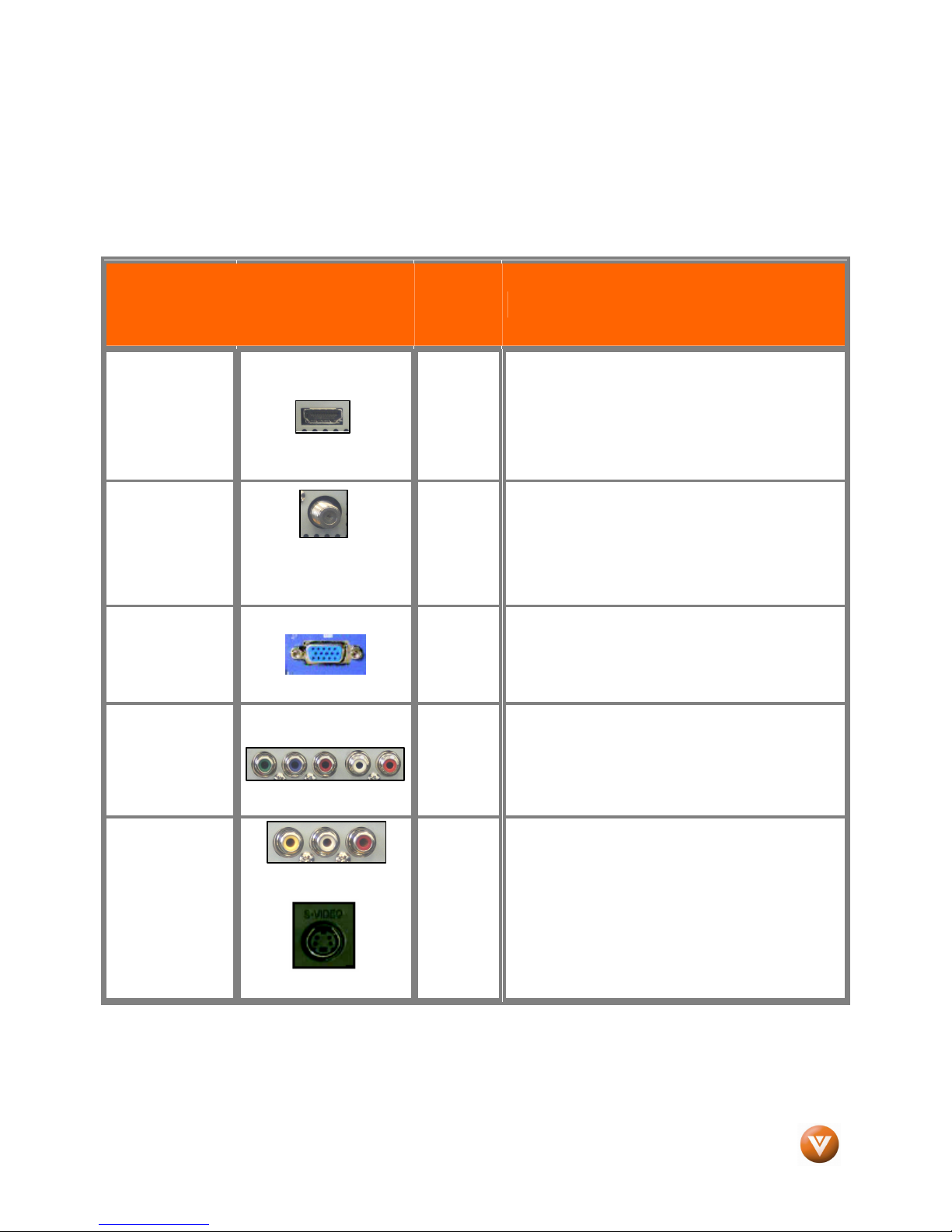
HDMI (High-Definition Multimedia Interface) - It is
the first and only industry-supported, uncompressed,
all-digital audio/video interface. HDMI provides an
interface between any audio/video source, such as a
set-top box, DVD player, or A/V receiver and an
audio and/or video monitor, such as a digital
television (DTV), over a single cable.
DTV Coaxial RF. When used for MPEG2 encoded
bit streams from ATSC broadcast programming, this
input takes advantage of the High Definition content.
- - - - - - - - - - - - - - - - - - - - - - - - - - - - - - - - - - - - - -
TV Coaxial RF. This is the connection for standard
NTSC TV using antenna or cable.
RGB PC (VGA) – This video input has separate red,
green and blue color components. The signal
carries horizontal and vertical sync information on
the green signal. This is most commonly used for
PC input.
Component1/2 - The video signal is separated into
three signals, one containing the black-and-white
information and the other two containing the color
information. This enhancement over S-Video takes
advantage of the superior picture provided by
progressive scan DVD players and HDTV formats.
Good
(analog)
Note: For more info refer to the Quick Start Guide
Version 4/1/2008 15
S-Video (AV1) - The video signal is separated into
two signals, one containing the black-and-white
Yellow,
Orange
and
Red
www.VIZIO.com
information and the other containing the color
information. Separating the color in this way avoids
‘cross color’ effects where closely spaced black and
white lines are erroneously displayed in color. It also
enables text to be displayed more sharply.
Composite (AV1/2) - The complete video signal is
carried through this single pin connector. This is the
most commonly used video connection.
VIZIO VO32L HDTV10A User Manual
2.2
2.2 Connecting Coaxial (RF)
2.22.2
2.2.1
2.2.1 Using Your Antenna or Digital Cable for DTV
2.2.12.2.1
Connecting Coaxial (RF)
Connecting Coaxial (RF)Connecting Coaxial (RF)
Using Your Antenna or Digital Cable for DTV
Using Your Antenna or Digital Cable for DTVUsing Your Antenna or Digital Cable for DTV
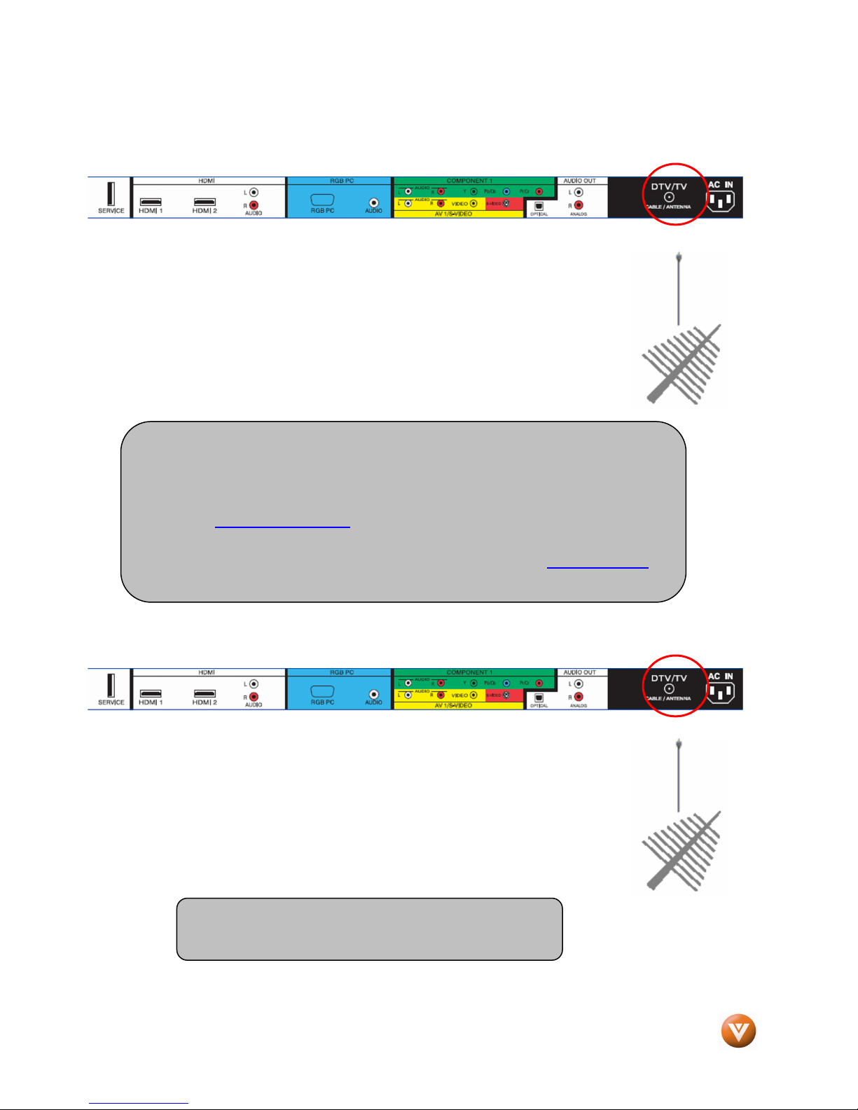
1. Turn off the power to the HDTV.
2. Connect the coaxial (RF) connector from your antenna or digital cable
(out-of-the-wall, not from the Cable Box) to the DTV/TV
CABLE/ANTENNA connector on the rear of the HDTV.
3. Turn on the power to the HDTV.
4. Select DTV using the INPUT button on the remote or side of the HDTV,
or directly by pressing the TV button on the Remote Control.
Note:
a) Not all digital TV broadcasts are High Definition (HD). Refer to the
program guides, or consult your cable, satellite or TV station operator.
b) Digital broadcasts are not available in all areas. Refer to
www.antennaweb.org for detailed information.
c) Make sure the antenna and coaxial cable are correctly grounded.
d) For Professional antenna installation contact us at www.VIZIO.com or
call 1-888-VIZIOCE (1-888-849-4623).
2.2.2
2.2.2 Using the Antenna or Cable through your VCR
2.2.22.2.2
Using the Antenna or Cable through your VCR
Using the Antenna or Cable through your VCRUsing the Antenna or Cable through your VCR
1. Turn off the power to the HDTV and VCR.
2. Connect the “Output to TV”, “RF Out” or “Antenna Out” connector on
the rear of your VCR to the DTV/TV CABLE/ANTENNA connector at
the rear of the HDTV.
3. Turn on the power to the HDTV and VCR.
4. Select TV using the INPUT button on the remote or side of the HDTV,
or directly by pressing the TV button on the Remote Control.
Note: If you have an off-air antenna or cable TV, connect
it to the “Antenna In” connector on the rear of your VCR.
Version 4/1/2008 16
www.VIZIO.com
VIZIO VO32L HDTV10A User Manual
for details.
2.3
2.3 Connecting Your HDTV Set
2.32.3
2.3.1
2.3.1 Using HDMI Input
2.3.12.3.1
HDTV Set-Top Boxes that have a HDMI digital interface should be connected to the HDMI input of the
LCD HDTV for optimal results.
Connecti
Connecting
ConnectiConnecti
Connecting Your HDTV Set----Top Box
Connecting Your HDTV SetConnecting Your HDTV Set
Using HDMI Input
Using HDMI InputUsing HDMI Input
Note: To maintain the display quality, use a VIZIO certified HDMI cable. Length is
available up to 10 meters. See www.vizioce.com or call 1-888-VIZIOCE (1-888-849-4623)
ng your HDTV Set
your HDTV Set----Top Box (Best)
ngng
your HDTV Set your HDTV Set
Top Box (Best)::::
Top Box (Best)Top Box (Best)
Top Box
Top BoxTop Box
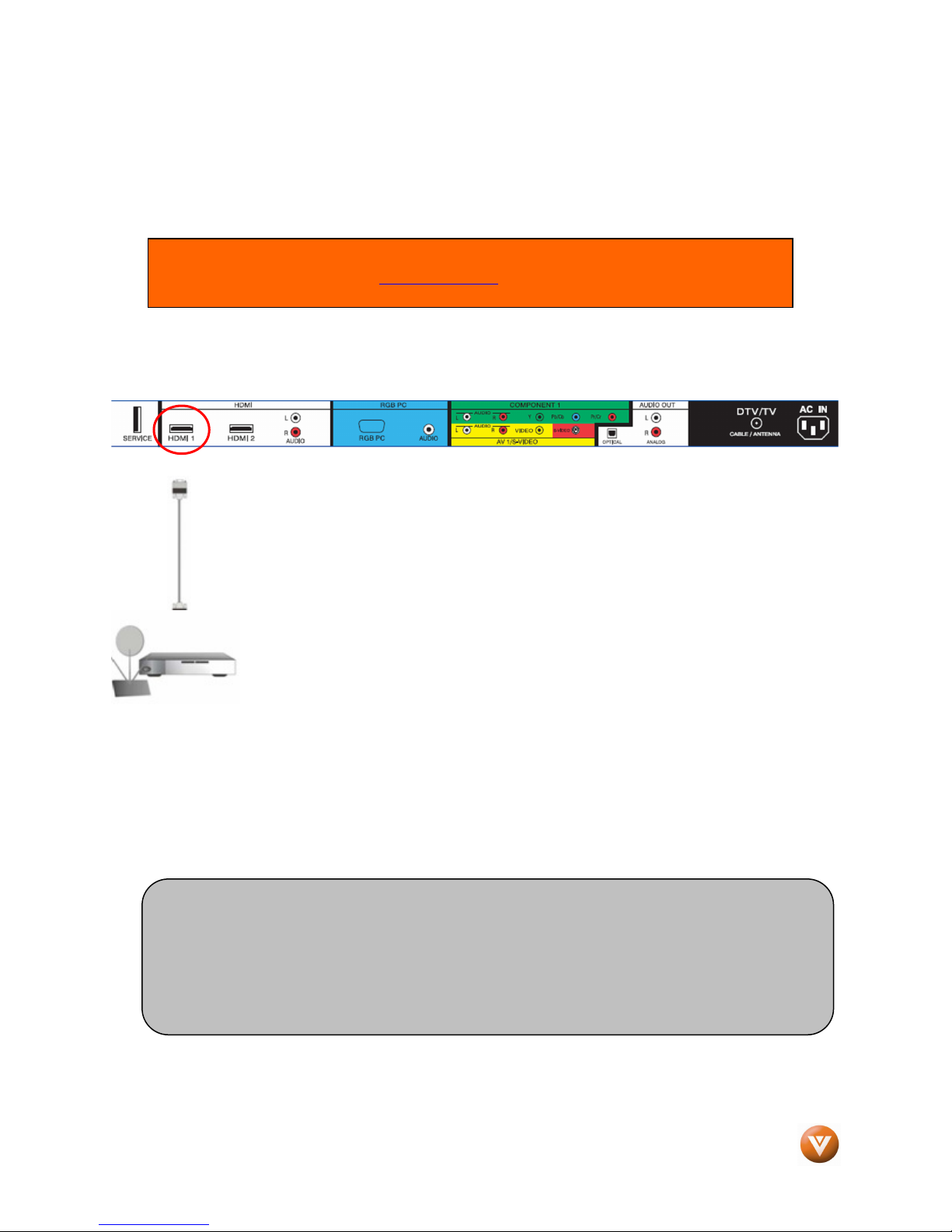
1. Turn off the power to the HDTV and HDTV Set-Top Box.
2. Connect a HDMI cable to the HDMI output of your HDTV Set-Top Box and the other end to
the HDMI Input (white color area) at the rear of the HDTV.
3. Turn on the power to the HDTV and HDTV Set-Top Box.
4. Select HDMI using the INPUT button on the remote or side of the HDTV, or directly by
pressing the HDMI button on the Remote Control.
Note:
a) The HDMI input on the HDTV supports High-bandwidth Digital Content Protection (HDCP).
HDCP encrypts the transmission between the video source and the digital display for
added security and protection.
b) Refer to your HDTV Set-Top Box user manual for more information about the video
output requirements of the product or consult your cable or satellite operator.
Version 4/1/2008 17
www.VIZIO.com
VIZIO VO32L HDTV10A User Manual
For HDTV Set
For HDTV Set----Top Boxes w
For HDTV SetFor HDTV Set
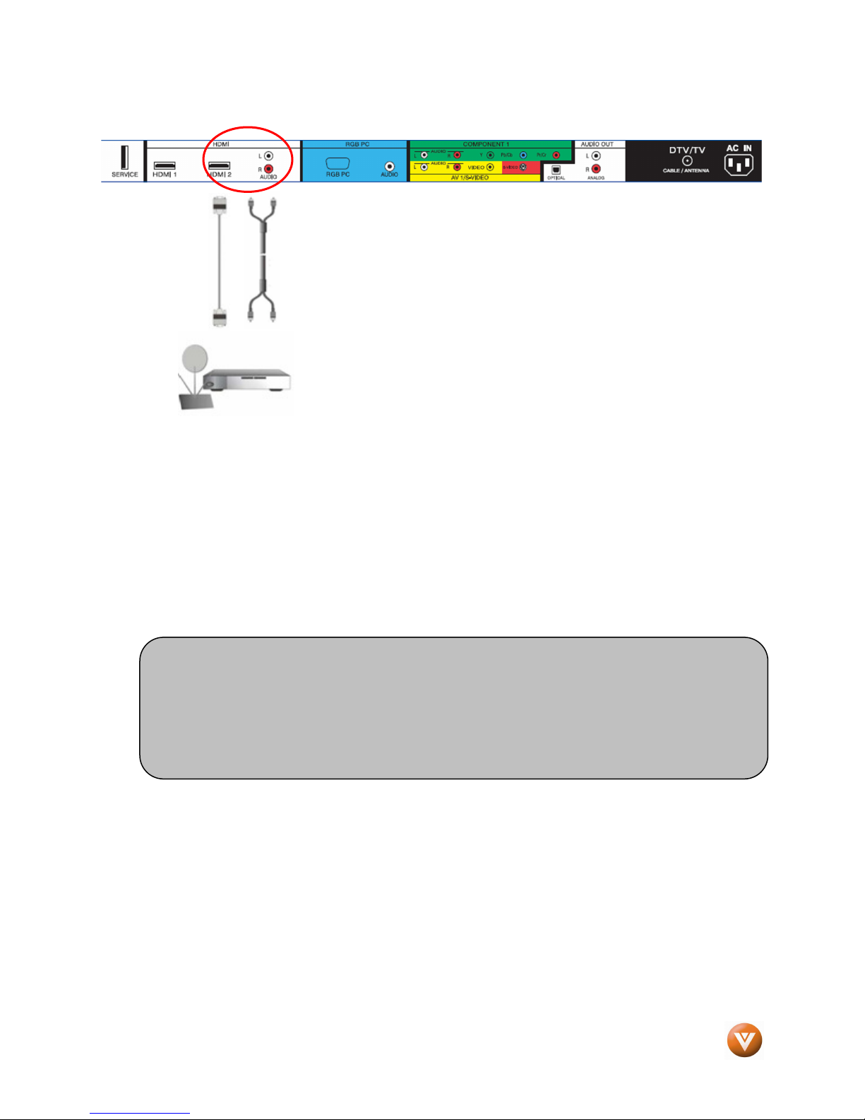
1. Turn off the power to the HDTV and HDTV Set-Top Box.
2. Using a HDMI-DVI cable, connect the DVI end to your HDTV Set-Top Box and the HDMI end
to the HDMI 2 Input (white color area) at the rear of the HDTV.
3. Using an audio cable (white and red connectors), connect the cable to the audio output
connectors associated with the DVI output on your HDTV Set-Top Box and connect the other
end to the audio connectors associated with the HDMI input (white area) at the rear of the
HDTV.
4. Turn on the power to the HDTV and HDTV Set-Top Box.
5. Select HDMI 2 using the INPUT button on the remote or side of the HDTV, or directly by
pressing the HDMI button on the Remote Control.
Note:
a) The HDMI input on the HDTV supports High-bandwidth Digital Content Protection
b) Refer to your HDTV Set-Top Box user manual for more information about the
Top Boxes with DVI
Top Boxes wTop Boxes w
(HDCP). HDCP encrypts the transmission between the video source and the
digital display for added security and protection.
video output requirements of the product or consult your cable or satellite operator.
ith DVI::::
ith DVIith DVI
Version 4/1/2008 18
www.VIZIO.com
2.3.2
2.3.2 Using Component Video
2.3.22.3.2
Connecting
Connecting your HDTV Set
ConnectingConnecting
Using Component Video
Using Component VideoUsing Component Video
your HDTV Set----Top Box (Better)
your HDTV Set your HDTV Set
Top Box (Better)::::
Top Box (Better)Top Box (Better)
VIZIO VO32L HDTV10A User Manual
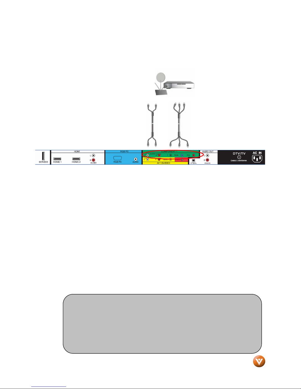
1. Turn off the power to the HDTV and HDTV Set-Top Box.
2. Connect the Y (green color) connector on your HDTV Set-Top Box to the corresponding Y
(green color) connector in the Component1 group (green color area - row of connectors
nearest to you when viewing from the rear of the TV) at the rear of the HDTV.
3. Connect the Pb (blue color) connector on your HDTV Set-Top Box to the corresponding Pb
(blue color) connector in the Component1 input (green color area - row of connectors nearest
to you when viewing from the rear of the TV) at the rear of the HDTV.
4. Connect the Pr (red color) connector on your HDTV Set-Top Box to the corresponding Pr (red
color) connector in the Component1 input (green color area - row of connectors nearest to
you when viewing from the rear of the TV) at the rear of the HDTV.
5. Using an audio cable (white and red connectors), connect the cable to the audio output
connectors associated with the Component output on your HDTV Set-Top Box and connect
the other end to the audio connectors associated with the Component1 input (green color
area) at the rear of the HDTV.
6. Turn on the power to the HDTV and HDTV Set-Top Box.
7. Select Component1 using the INPUT button on the remote or side of the HDTV, or directly by
pressing the Component button on the Remote Control.
Note:
a) Refer to your HDTV Set-Top Box user manual for more information about the
video output requirements of the product or consult your cable or satellite
operator.
b) If Component1 is already connected to another device, or you do not wish to
use Component1, connect the green, blue and red video adapters into
Component2 connectors (purple color) and the audio connectors into the
AV2 connectors (orange color).
Version 4/1/2008 19
www.VIZIO.com
VIZIO VO32L HDTV10A User Manual
2.4
2.4 Connecting Your Basic Set
2.42.4
2.4.1
2.4.1 Using Composite Video
2.4.12.4.1
Connecting Your Basic Set----Top Box
Connecting Your Basic SetConnecting Your Basic Set
Using Composite Video
Using Composite VideoUsing Composite Video
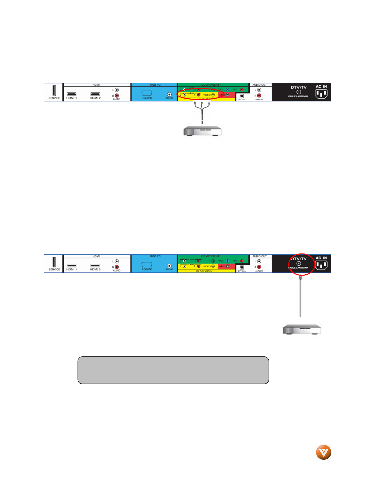
1. Turn off the power to the HDTV and
Set-Top Box.
2. Using the AV Cable, connect the Video (yellow color) connector on your Set-Top Box to the
corresponding Video (yellow color) connector in the AV1 input (yellow color area) at the rear
of the HDTV.
3. Using the white and red connectors, connect the cable to the audio output connectors
associated with the Video output on your Set-Top Box and connect the other end to the audio
connectors associated with the AV1 input (yellow color area) at the rear of the HDTV.
4. Turn on the power to the HDTV and Set-Top Box.
5. Select AV1 using the INPUT button on the remote or side of the HDTV, or directly by
pressing the AV button on the Remote Control.
Top Box
Top BoxTop Box
2.4.2
2.4.2 Using Coax (RF)
2.4.22.4.2
Using Coax (RF)
Using Coax (RF)Using Coax (RF)
1. Turn off the power to the HDTV and Set-Top Box.
2. Using a Coax (RF) cable, connect one end to the TV OUT (RF) on your Set
Top Box and the other end to the DTV/TV input at the rear of the HDTV.
3. Turn on the power to the HDTV and Set-Top Box.
4. Select TV using the INPUT button on the remote or side of the HDTV, or
directly by pressing the TV button on the Remote Control.
Note: Refer to your Set Top Box user manual for more information
about selecting the video or RF output of the product.
Version 4/1/2008 20
www.VIZIO.com
VIZIO VO32L HDTV10A User Manual
2.5
2.5 Connecting Your DVD Player
2.52.5
You have several options for connecting your DVD player to your VO32L HDTV10A; HDMI, Component,
AV (S-Video or Composite) inputs. Based on your configuration, you can decide which option is right for
you.
2.5.1
2.5.1 Using HDMI Input
2.5.12.5.1
DVD players that have a digital interface such as HDMI (High Definition Multimedia Interface) should be
connected to the HDMI input of the VIZIO VO32L HDTV10A for optimal results.
Connecting
Connecting your DVD Player (Best)
ConnectingConnecting
Connecting Your DVD Player
Connecting Your DVD PlayerConnecting Your DVD Player
Using HDMI Input
Using HDMI InputUsing HDMI Input
Note: To maintain the display quality, use a VIZIO certified HDMI cable. Length is available up to
10 meters. See www.VIZIOCE.com or call 1-888-VIZIOCE (1-888-849-4623) for details.
your DVD Player (Best)::::
your DVD Player (Best) your DVD Player (Best)
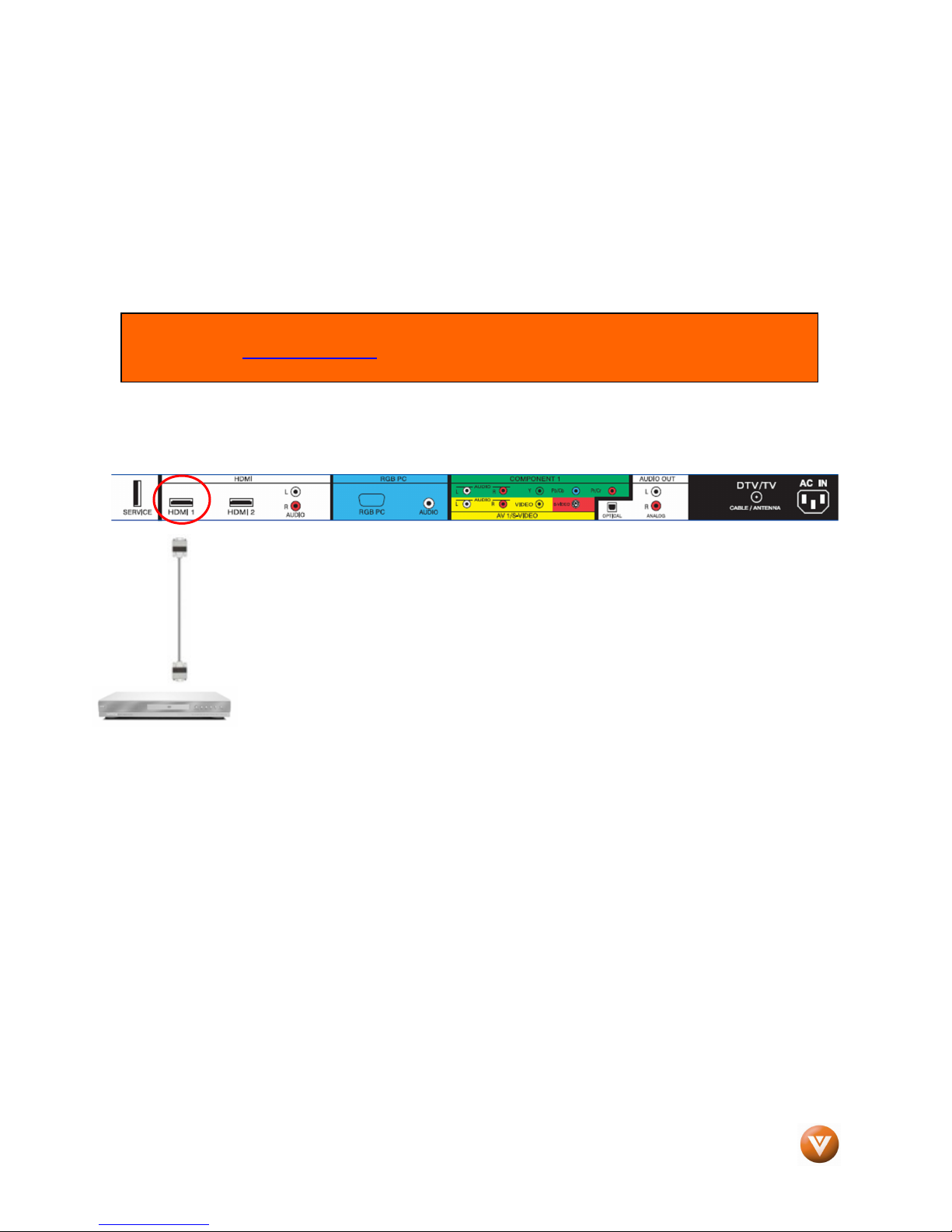
1. Turn off the power to the HDTV and DVD player.
2. Connect a HDMI cable to the HDMI output of your DVD player and the
other end to the HDMI1 Input (white color area) at the rear of the HDTV.
3. Turn on the power to the HDTV and DVD player.
4. Select HDMI1 using the INPUT button on the remote or side of the HDTV,
or directly by pressing the HDMI button on the Remote Control.
Version 4/1/2008 21
www.VIZIO.com
VIZIO VO32L HDTV10A User Manual
For DVD Players with DVI
For DVD Players with DVI::::
For DVD Players with DVIFor DVD Players with DVI
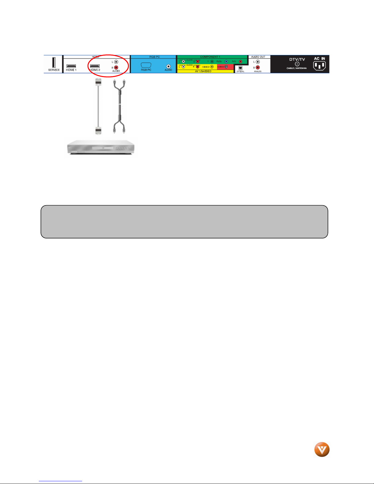
1. Turn off the HDTV and DVD player.
2. Using a HDMI-DVI cable, connect the DVI end to your
DVD player and the HDMI2 end to the HDMI Input (white
color area) at the rear of the HDTV.
3. Connect an audio cable (white and red connectors) to the
audio output connectors associated with the DVI output of
the DVD player and connect the other end to the audio
connectors by the HDMI input (white area) at the rear of the HDTV.
4. Turn on the power to the HDTV and your DVD player.
5. Select HDMI 2 using the INPUT button on the remote or side of the HDTV, or directly by
pressing the HDMI button on the Remote.
Note: Refer to your DVD player user manual for more information about the video output
requirements of the product.
Version 4/1/2008 22
www.VIZIO.com
VIZIO VO32L HDTV10A User Manual
2.5.2
2.5.2 Using Component Video
2.5.22.5.2
Connecting
Connecting your DVD Player (Better)
ConnectingConnecting
Using Component Video
Using Component VideoUsing Component Video
your DVD Player (Better)::::
your DVD Player (Better) your DVD Player (Better)
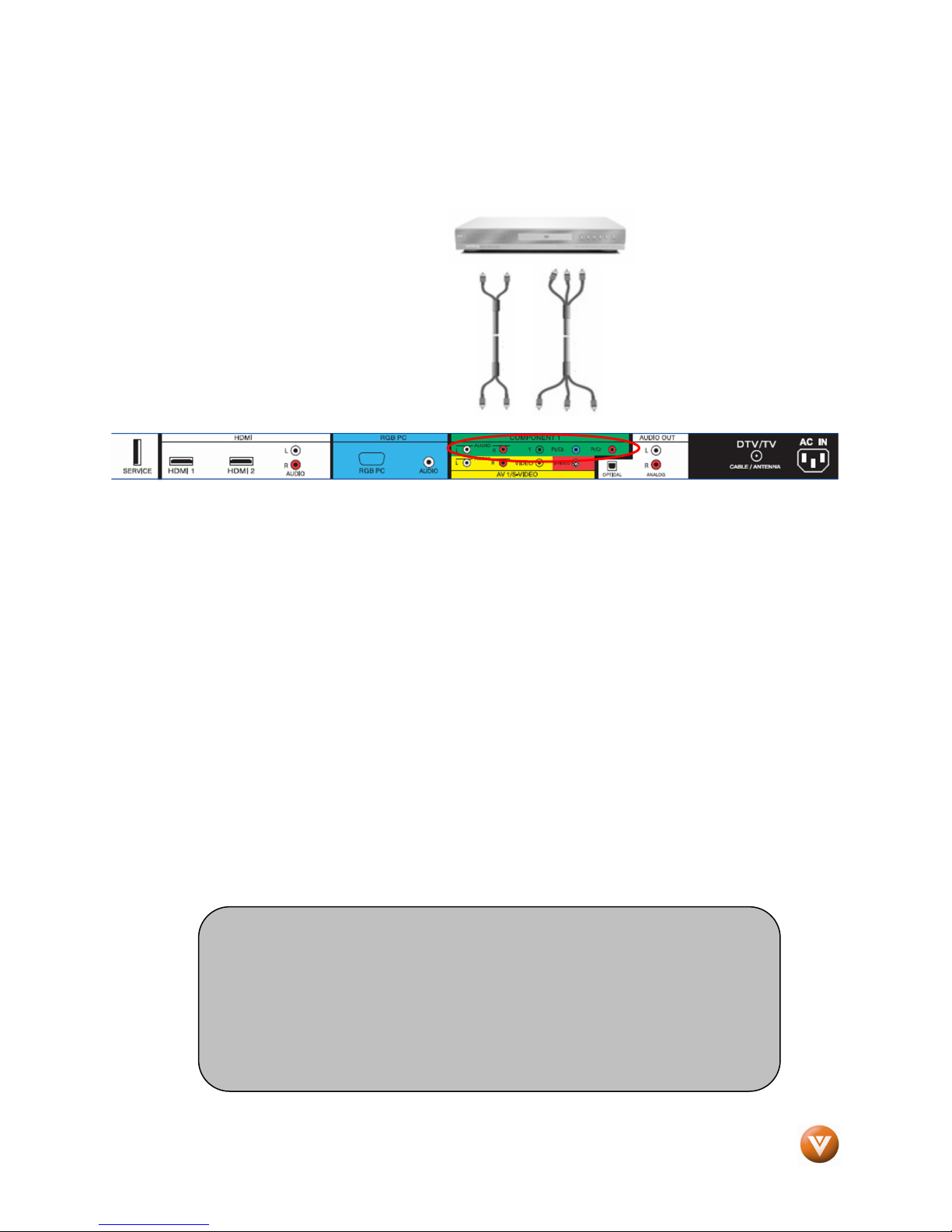
1. Turn off the power to the HDTV and DVD player.
2. Connect the Y (green color) connector on your DVD player to the corresponding Y (green
color) connector in the Component1 input (green color area - row of connectors nearest to
you when viewing from the rear of the TV) at the rear of the HDTV.
3. Connect the Pb (blue color) connector on your DVD player to the corresponding Pb (blue
color) connector in the Component1 input (green color area - row of connectors nearest to
you when viewing from the rear of the TV) at the rear of the HDTV.
4. Connect the Pr (red color) connector on your DVD player to the corresponding Pr (red color)
connector in the Component1 input (green color area - row of connectors nearest to you
when viewing from the rear of the TV) at the rear of the HDTV.
5. Using an audio cable (white and red connectors), connect the cable to the audio output
connectors associated with the Component1 output on your DVD player and connect the
other end to the audio connectors associated with the Component input (green color area) at
the rear of the HDTV.
6. Turn on the power to the HDTV and DVD player.
7. Select Component1 using the INPUT button on the remote or side of the HDTV, or directly by
pressing the Component1 button on the Remote Control.
Note:
a) Refer to your DVD player user manual for more information about the
video output requirements of the product.
b) If Component1 is already connected to another device, or you do not
wish to use Component1, connect the green, blue and red video
adapters into Component2 connectors (purple color) and the audio
connectors into the AV2 connectors (orange color).
Version 4/1/2008 23
www.VIZIO.com
VIZIO VO32L HDTV10A User Manual
2.5.3
2.5.3 Using S
2.5.32.5.3
Connecting
Connecting your DVD Player (Good):
ConnectingConnecting
Using S----Video (AV1/S
Using SUsing S
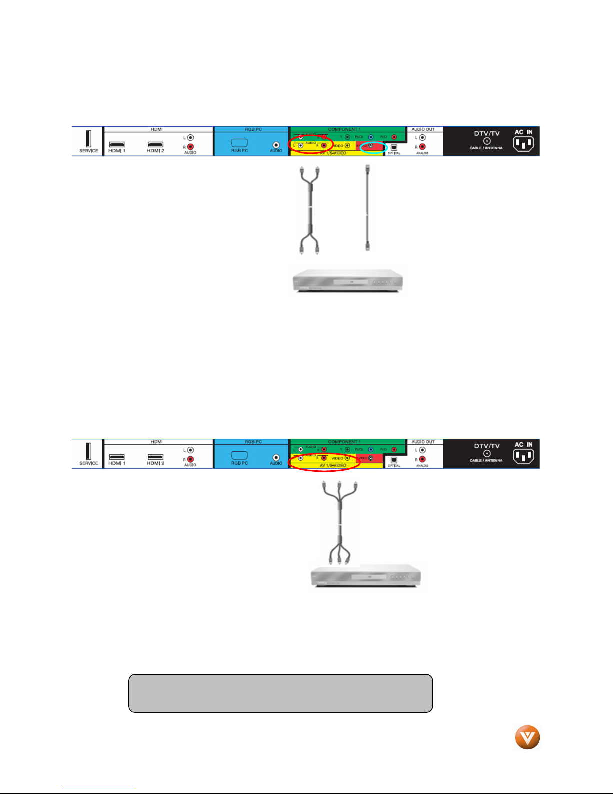
1. Turn off the power to the HDTV and DVD player.
2. Connect the S-Video jack on the rear of your DVD
player to the S-Video jack in the AV1/S-VIDEO input
(yellow/red area) at the rear of the HDTV.
3. Connect an audio cable (white
and red connectors) to the audio
output connectors associated with
the S-Video output on your DVD
player and connect the other end to the audio connectors associated with the AV input
(yellow/red area) at the rear of the HDTV.
4. Turn on the power to the HDTV and DVD player.
5. Select AV1 using the INPUT button on the remote or side of the HDTV, or directly by
pressing the AV button on the Remote Control.
Video (AV1/S----VIDEO)
Video (AV1/SVideo (AV1/S
your DVD Player (Good):
your DVD Player (Good): your DVD Player (Good):
VIDEO)
VIDEO)VIDEO)
2.5.4
2.5.4 Using Composite (AV) Video Input
2.5.42.5.4
Connecting
Connecting y
ConnectingConnecting
Using Composite (AV) Video Input
Using Composite (AV) Video InputUsing Composite (AV) Video Input
your DVD Player (Good)
our DVD Player (Good) ::::
y y
our DVD Player (Good) our DVD Player (Good)
Turn off the power to the HDTV and DVD player.
1. Connect the Video (yellow color)
connector on your DVD player to the
Video (yellow color) connector in the
AV/S-VIDEO input (yellow/red color
area - row of connectors furthest from
you when viewing from the rear of the
HDTV) at the rear of the HDTV.
2. Connect the R (red color) and L (white
color) audio connectors on your DVD player to the corresponding R (red color) and L (white
color) audio input connectors in the AV input (yellow/red color area - row of connectors
furthest from you when viewing from the rear of the TV) on the rear of the HDTV.
3. Turn on the power to the HDTV and DVD Player.
4. Select AV1 using the INPUT button on the remote or side of the HDTV, or directly by
pressing the AV button on the Remote Control.
Note: Refer to your DVD player user manual for more
information about the video output requirements of the product.
Version 4/1/2008 24
www.VIZIO.com
VIZIO VO32L HDTV10A User Manual
2.6
2.6 Connecting Your VCR
2.62.6
Connecting Your VCR or Video Camera
Connecting Your VCRConnecting Your VCR
or Video Camera
or Video Camera or Video Camera
1. Turn off the HDTV and VCR or
Video Camera.
2. Connect the S-Video jack on the rear of your VCR or Video Camera to the S-Video jack in the
AV input (yellow/red area) at the rear of the HDTV.
3. Connect an audio cable (white and red connectors) cable to the audio output connectors
associated with the S-Video output on your VCR or Video Camera and connect the other end
to the audio connectors associated with the AV input (yellow/red area) at the rear of the
HDTV.
4. Turn on the power to the HDTV and VCR or Video Camera.
5. Select AV1 using the INPUT button on the remote or side of the HDTV, or directly by
pressing the AV button on the Remote Control.
Note: Refer to your VCR or Video Camera user manual for more
information about the video output requirements of the product.
Version 4/1/2008 25
www.VIZIO.com
VIZIO VO32L HDTV10A User Manual
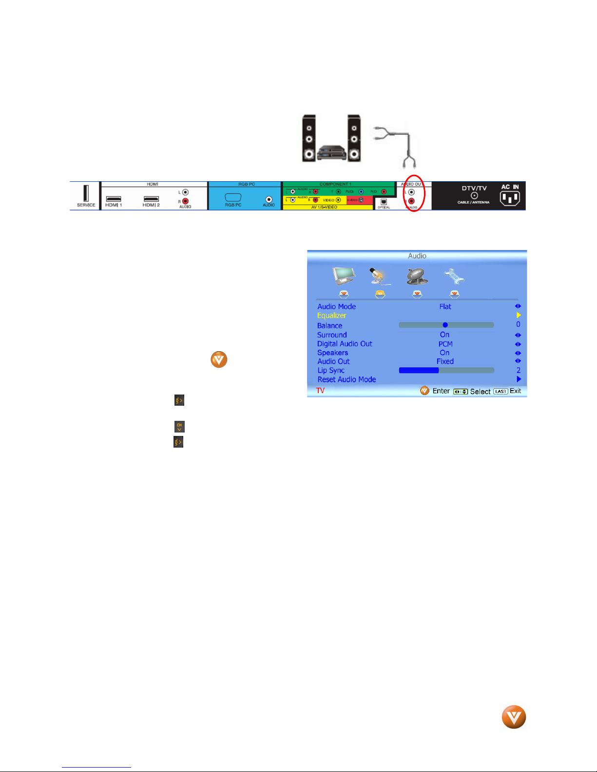
2.7
2.7 Connecting an external Receiver/Amp
2.72.7
7. Press the on the remote control to select OFF so that the sound from the LCD HDTV will
Connecting an external Receiver/Amp
Connecting an external Receiver/Amp Connecting an external Receiver/Amp
1. Turn off the power to the LCD HDTV and Receiver/Amp.
2. Using an audio cable (white and red
connectors), connect the cable to the
audio input connectors on the
Receiver/Amp and connect the other
end to the ANALOG OUT (white area)
audio connectors at the rear of the
LCD HDTV.
3. Turn on the power to the LCD HDTV
and Receiver/Amp.
4. Then press the button on the
remote control to open the On-Screen
Display (OSD) menu.
5. Press the on the remote control to
select the Audio Adjust menu.
6. Press the on the remote control to select SPEAKERS.
now be routed through your Receiver/Amp system.
Version 4/1/2008 26
www.VIZIO.com
VIZIO VO32L HDTV10A User Manual
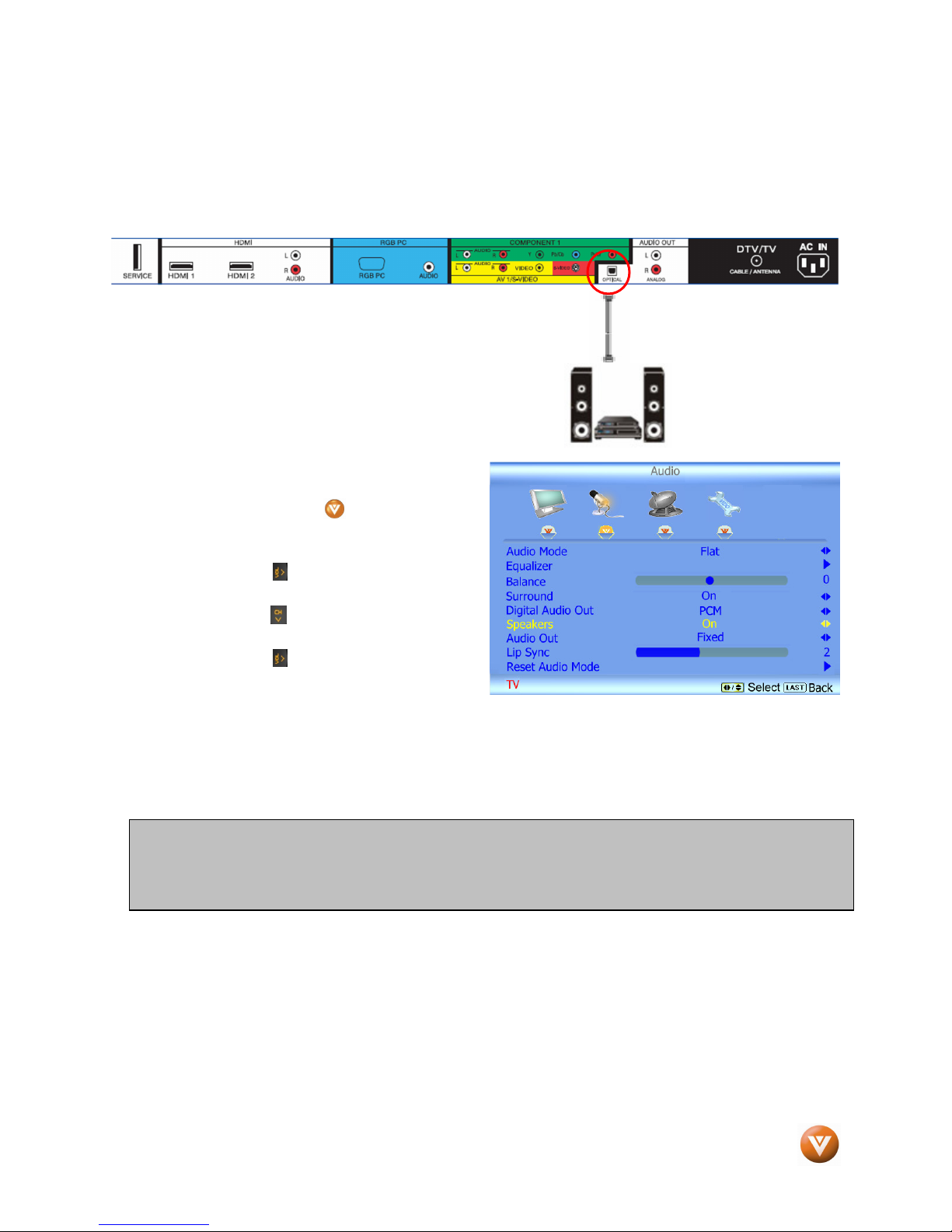
2.7.1
2.7.1 Optical Output of Audio
2.7.12.7.1
If your sound system has a SPDIF (optical) digital audio input you can connect it to the optical AUDIO
OUT (white area) at the rear of the VO32L HDTV10A.
Press the LAST key once to return to the previous screen or repeatedly to return to your program if task
has been completed.
Optical Output of Audio received
Optical Output of AudioOptical Output of Audio
1. Turn off the power to the LCD HDTV and Receiver/Amp.
2. Using an SPDIF cable, connect the cable to the
audio input connector on the Receiver/Amp and
connect the other end to the OPTICAL OUT (white
area) audio connectors at the rear of the LCD
HDTV.
3. Turn on the power to the LCD HDTV
and Receiver/Amp.
4. Then press the button on the
remote control to open the On-Screen
Display (OSD) menu.
5. Press the on the remote control to
select the Audio Adjust menu.
6. Press the on the remote control to
select SPEAKERS.
7. Press the on the remote control to
select OFF so that the sound from the
LCD HDTV will now be routed through
your Receiver/Amp system.
Note:
a) Refer to your Receiver/Amp user manual to select the corresponding audio input.
b) The audio output is not amplified and cannot be connected directly to external speakers.
received
received received
Version 4/1/2008 27
www.VIZIO.com
 Loading...