

Page 1
Service Manual
Model #: VIZIO VO32L HDTV10A_
MT5381P-SST(EU)_LPL/AUO
V, Inc
320A Kalmus Drive Costa Mesa, CA 92626
TEL : +714-668-0588 FAX :+714-668-9099
Top Confidential
Page 2

Table of Contents
CONTENTS PAGE
Sections
1. Features 1-1
2. Specifications 2-1
3. On Screen Display 3-1
4. Factory Preset Timings
5. Pin Assignment
4-1
5-1
6. Main Board I/O Connections 6-1
7. Theory of Circuit Operation 7-1
8. Waveforms 8-1
9. Trouble Shooting 9-1
10. Block Diagram 10-1
11. Spare parts list 11-1
12. Complete Parts List 12-1
Appendix
1. Main Board Circuit Diagram
2. Main Board PCB Layout
3. Assembly Explosion Drawing
Block Diagram
VIZIO VO32L HDTV10A_MT5381P-SST(EU)LPL/AUO Service Manual
Page 3

VINC Service Manual
VIZIO VO32L HDTV10A_MT5381P-SST(EU)LPL/AUO
COPYRIGHT © 2000 V, INC. ALL RIGHTS RESERVED.
IBM and IBM products are registered trademarks of International Business Machines Corporation.
Macintosh and Power Macintosh are registered trademarks of Apple Computer, Inc.
VINC and VINC products are registered trademarks of V, Inc.
VESA, EDID, DPMS and DDC are registered trademarks of Video Electronics Standards
Association (VESA).
Energy Star is a registered trademark of the US Environmental Protection Agency (EPA).
No part of this document may be copied, reproduced or transmitted by any means for any purpose
without prior written permission from VINC.
FCC INFORMATION
This equipment has been tested and found to comply with the limits of a Class B digital device,
pursuant to part 15 of the FCC Rules. These limits are designed to provide reasonable protection
against harmful interference in a residential installation. This equipment generates, uses and can
radiate radio frequency energy, and if not installed and used in accordance with the instructions,
may cause harmful interference to radio communications. However, there is no guarantee that the
interference will not occur in a particular installation. If this equipment does cause unacceptable
interference to radio or television reception, which can be determined by turning the equipment off
and on, the user is encouraged to try to correct the interference by one or more of the following
measures -- reorient or relocate the receiving antenna; increase the separation between
equipment and receiver; or connect the into an outlet on a circuit different from that to which the
receiver is connected.
FCC WARNING
To assure continued FCC compliance, the user must use a grounded power supply cord and the
provided shielded video interface cable with bonded ferrite cores. Also, any unauthorized changes
or modifications to Amtrak products will void the user’s authority to operate this device. Thus VINC
Will not be held responsible for the product and its safety.
CE CERTIFICATION
This device complies with the requirements of the EEC directive 89/336/EEC with regard to
“Electromagnetic compatibility.”
SAFETY CAUTION
Use a power cable that is properly grounded. Always use the AC cords as follows – USA (UL);
Canada (CSA); Germany (VDE); Switzerland (SEV); Britain (BASEC/BS); Japan (Electric
Appliance Control Act); or an AC cord that meets the local safety standards.
VIZIO VO32L HDTV10A_MT5381P-SST(EU)LPL/AUO Service Manual
Page 4

Chapter 1 Features
1. Built in TV channel selector for TV viewing.
2. Simulatnueous display of PC and TV images.
3. Connectable to PC’s analog RGB port.
4. Built in S-video, HDTV, composite video, HDMI and TV out.
5. Built in auto adjust function for automatic adjument of screen display.
6. Smoothing function enables display of smooth texts and graphics even if image
withresolution lower than 1366x768 is magnified.
7. Advanced video functions for personal favor.
8. Power saving to reduce consumption power too less than 3W.
9. On Screen Display: user can define display mode (i.e. color, brightness, contrast,
sharpness, backlight), sound setting, TV channel program, aspect and gamma or
reset all setting.
CONFIDENTIAL – DO NOT COPY Page 1-1
File No. SG-0263
Page 5

Chapter 2 Specification
1. TFT-LCD CHARACTERISTICS
Model Name: LPL LC320WXN-SAC1
Size: 3151inch
Display Size: 31.51 inches (800.4mm) diagonal
Outline Dimension: 760.0 mm (H) x 450.0 mm (V) x 48.0 mm (D) (Typ.)
Pixel Pitch: 0.170mm x 0.510mm x RGB
Pixel Format: 1366 horiz. By 768 vert. Pixels RGB strip arrangement
Display Operating Mode: Transmissive mode, normally Black
Surface Treatment: Hard Coating (3H) ,Anti-glare treatment of the front
polarizer (Haze : 13%).
Model Name: AUO T315XW02_VL
Size: 3151inch
Display Size: 31.51 inches (800.4mm) diagonal
Outline Dimension: 760.0 mm (H) x 450.0 mm (V) x 45.0 mm (D) (Typ.)
Pixel Pitch: 0.51075mm
Pixel Format: RGB vertical stripe
Display Operating Mode: Transmissive mode, normally Black
Surface Treatment: Hard Coating (3H) ,Anti-glare treatment of the front
polarizer (Haze : 11%).
2. TFT-LCD OPTICAL CHARACTERISTICS
Model Name: LPL LC320WXN-SAC1
Contrast ratio :CR : 1100(Typ)
Surface Luminance, White: 500 cd/m
2 (Typ)
Luminance Variation, δ=1.3 (Max)
Response Time = 8 ms (Max=12ms)
Viewing Angle (CR>10)
Left: 89°typ.
Right: 89°typ.
Top: 89°typ.
Bottom: 89°typ.
CONFIDENTIAL – DO NOT COPY
Page 2-1
File No. SG-0263
Page 6

Model Name: AUO T315XW02_VL
Contrast ratio :CR : 2500(Typ)
Surface Luminance, White: 450 cd/m
2 (Typ)
Luminance Variation, δ=1.3 (Max)
Response Time = 6.5 ms (Max=25ms)
Viewing Angle
Left: 89°typ.
Right: 89°typ.
Top: 89°typ.
Bottom: 89°typ.
3. Input Connectors
Video Inputs
1x RF (Combo, F Connector for internal NTSC /ATSC/QAM Tuner)
3x HDMI with HDCP plus Stereo Analog Audio
2x Component YPbPr plus Stereo Audio
2x Composite Video plus Stereo Audio
1x S-Video plus Stereo Audio
1x Analog RGB plus Stereo Audio
4 x Stereo RCA Jack (R/L), 1 x PC Mini-Jack
USB firmware update
Audio Input
1x Stereo Audio (RCA)
1x PC mini jack
4. POWER SUPPLY
Input Voltage Level: 120 Vac, 50/ 60 Hz
Power Consumption: 170W MAXPower OFF: to less than 1W MAX
5. Speaker
Output 12W (max) X2
CONFIDENTIAL – DO NOT COPY
Page 2-2
File No. SG-0263
Page 7

6. ENVIRONMENT
Model Name: LPL LC320WXN-SAC1
Operating Temperature: 0°C ~50°C (Ambient)
Operating Humidity: Ta= 40 °C, 90%RH (Non-condensing)
Model Name: AUO T315XW02_VL
Operating Temperature: -5°C ~50°C (Ambient)
7. DIMENSIONS (Physical dimension)
Width: 760 mm. +/- 20 mm
Depth: 48 mm +/- 20 mm
Height: 450 mm +/- 20 mm
8. WEIGHT (Physical weight)
6150g (LPL LC320WXN-SAC1)
6500g (AUO T315XW02_VL)
Precaution
Please pay attention to the followings when you use this TFT LCD module.
1. OPERATING PRECAUTIONS
(1) The spike noise causes the mis-operation of circuits. It should be lower
than following voltage :
V=±200mV(Over and under shoot voltage)
(2) Response time depends on the temperature. (In lower temperature, it
becomes longer.)
(3) Brightness depends on the temperature. (In lower temperature, it becomes
lower.)And in lower temperature, response time (required time that
brightness is stable after turned on) becomes longer.
(4) Be careful for condensation at sudden temperature change. Condensation
makes damage to polarizer or electrical contacted parts. And after fading
condensation, smear or spot will occur.
(5) When fixed patterns are displayed for a long time, remnant image is likely
to occur.
(6) Module has high frequency circuits. System manufacturers shall do
sufficient suppression to the electromagnetic interference. Grounding and
shielding methods may be important to minimize the interference.
CONFIDENTIAL – DO NOT COPY
File No. SG-0263
Page 2-3
Page 8

2. HANDLING PRECAUTIONS FOR PROTECTION
(1) The protection film is attached to the bezel with a small masking tape.
When the protection film is peeled off, static electricity is generated
between the film and polarizer. This should be peeled off slowly and
carefully by people who are electrically grounded and with well ion-blown
equipment or in such a condition, etc.
(2) When the module with protection film attached is stored for a long time,
sometimes there remains a very small amount of glue still on the bezel after
the protection film is peeled off.
(3) You can remove the glue easily. When the glue remains on the bezel
surface or its vestige is recognized, please wipe them off with absorbent
cotton waste or other soft material like chamois soaked with
normal-hexane.
CONFIDENTIAL – DO NOT COPY
Page 2-4
File No. SG-0263
Page 9

Chapter 3 On Screen Display
On Screen Display (OSD) is a friendly interface providing the function adjusting in our system.
Customers could operate it only by few buttons. There is the introduction of the OSD.
Main unit button
MENU OK
CH ▲ ↑
CH ▼ ↓
VOL + ←
VOL - →
Input
[MENU]
“MENU” button could star the OSD which could adjust the performance and set up the setting
between the different input sources. There are the structures.
TV Source
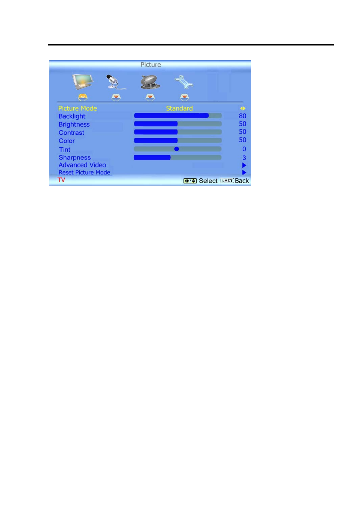
A. PICTURE ADJUST:
a. PICTURE MODE
(CUSTOM/STANDARD/MOVIE/GAME/VIVID/FOOTBALL/GOLF/BASKETBALL/BASEBA
LL)
b. BACKLIGHT (0~100)
c. BRIGHTNESS (0~100)
d. ONTRAST (0~100)
e. COLOR (0~100)
f. TINT (-32~+32)
g. SHARPNESS (0~7)
h. ADVANCED VIDEO
i. RESET PICTURE MODE
CONFIDENTIAL – DO NOT COPY
Page 3-1
File No. SG-0263
Page 10
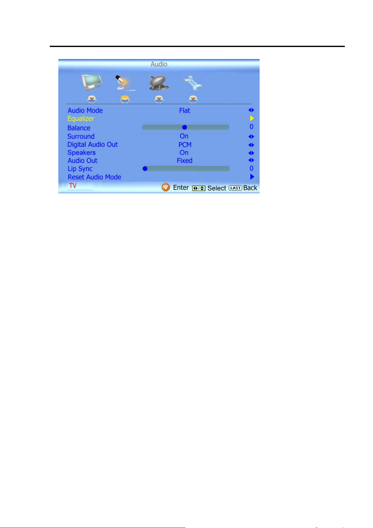
B. AUDIO ADJUST:
a. AUDIO Mode (FLAT/ROCK/POP/CLASSIC/JAZZ/)
b. EQUALIZER
c. BALANCE (-50~+50)
d. SURROUND (ON/OFF)
e. DIGITAL AUDIO OUT (PCM/OFF/DOBLY DIGITAL)
f. SPEAKERS (ON/OFF)
g. AUDIO OUT (FIXED/VARIABLE)
h. LIP SYNC(0~5)
RESET AUDIO MODE
CONFIDENTIAL – DO NOT COPY
Page 3-2
File No. SG-0263
Page 11
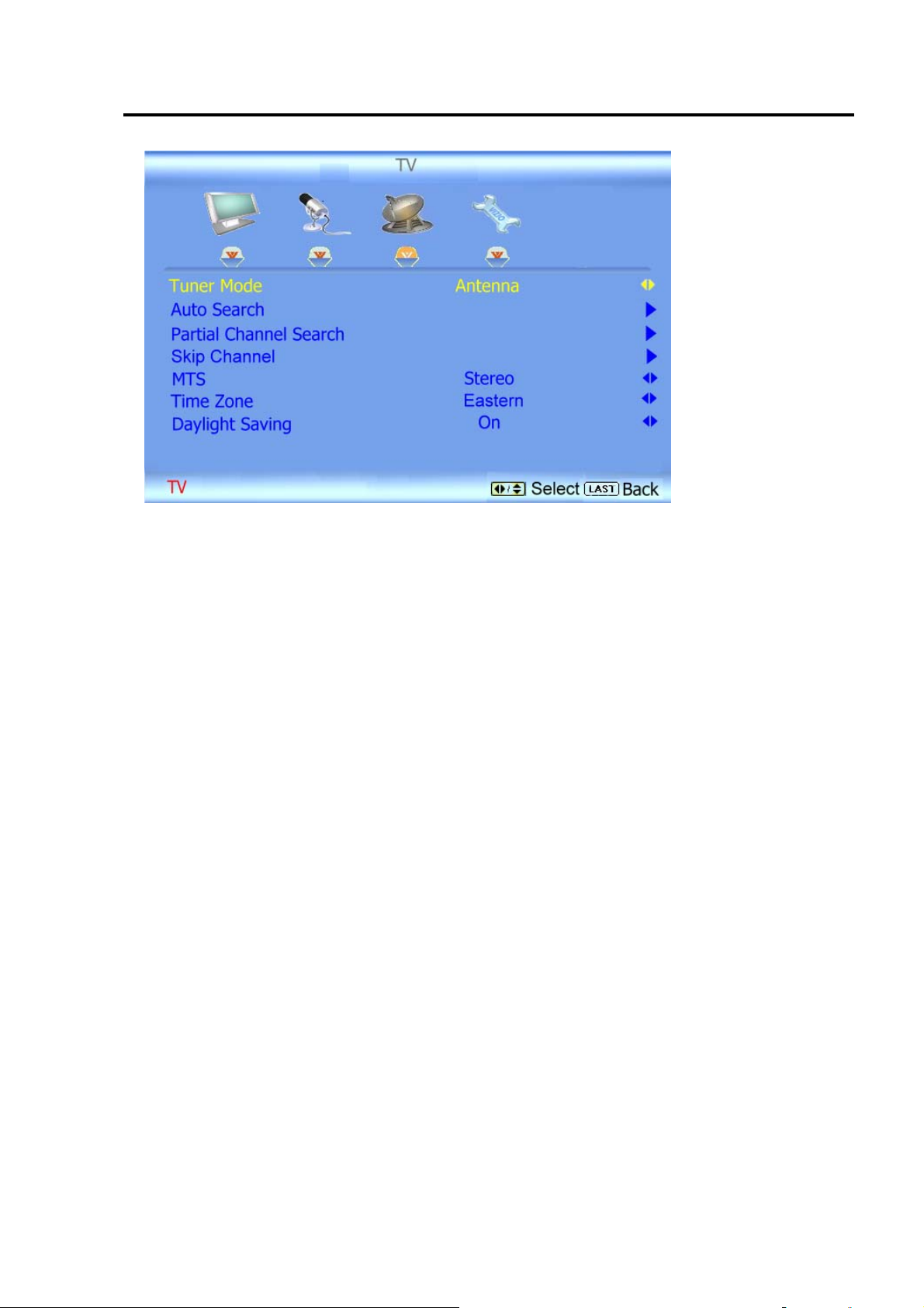
C. TV:ATV
a. TUNER MODE(ANTENNA/CABLE)
b. AUTO SEARCH
c. PARTIAL CHANNEL SEARCH
d. SKIP CHANNEL
e. MTS(STEREO/SAP/MONO)
f. TIME ZONE (EASTERN/ATLANTIC/INDIANA/
g. CENTRAL/MOUNTAIN/ARIZONA/
h. NEWFOUNDLAND/PACIFIC/ALASKA/ HAWAII)
i. DAYLIGHT SAVING(ON/OFF)
CONFIDENTIAL – DO NOT COPY
Page 3-3
File No. SG-0263
Page 12
D. TV:DTV
a. TUNER MODE(ANTENNA/CABLE)
b. AUTO SEARCH
c. PARTIAL CHANNEL SEARCH
d. SKIP CHANNEL
e. MTS(LANGUAGE1/LANGUAGE2/
f. LANGUAGE3)
g. TIME ZONE (EASTERN/ATLANTIC/INDIANA/
h. CENTRAL/MOUNTAIN/ARIZONA/
i. NEWFOUNDLAND/PACIFIC/ALASKA/
j. HAWAII)
k.
DAYLIGHT SAVING(ON/OFF)
CONFIDENTIAL – DO NOT COPY
Page 3-4
File No. SG-0263
Page 13

E. SETUP:(ATV only)
a. LANGUAGE (ENGLISH/FRANCAIS/ ESPANOL)
b. PIP(PIP MODE/PIP SOURCE/PIP POSITION/ SIZE/AUDIO SOURCE)
c. SLEEP TIMER(OFF/30 MINUTES/60 MINUTES/90 MINUTES/120 MINUTES)
d. WIDE(WIDE/PANORAMIC/NORMAL)
e. INPUT NAMING
f. CC(CC ON MUTE/CC/DIGITAL CC STYLE)
g. H/V POSITION (H.POSITION/V.POSITION/ H.SIZE/V.SIZE)
h. RESET ALL SETTING
CONFIDENTIAL – DO NOT COPY
Page 3-5
File No. SG-0263
Page 14

F. PIP:
a. PIP MODE(OFF/PIP/POP)
b. PIP SOURCE(TV/COMPONENT1/ COMPONENT2/RGB/HDMI1/HDMI2/HDMI3)
c. POP POSITION(BOTTOM RIGHT/ BOTTOM CENTER/ BOTTOM LEFT/MIDDLE
LEFT/TOP LEFT/TOP CENTER/TOP RIGHT/MIDDLE RIGHT/)
d. SIZE(SMALL/MEDIUM/LARGE)
e. AUDIO SOURCE(MAIN/PIP)
CONFIDENTIAL – DO NOT COPY
Page 3-6
File No. SG-0263
Page 15

RGB Mode
A. PICTURE ADJUST:
a. AUTO ADJUST
b. BACKLIGHT (0~100)
c. BRIGHTNESS (0~100)
d. CONTRAST (0~100)
e. COLOR TEMPERATURE (9300/6500/CUSTOM)
f. H-SIZE (0~255)
g. H.POSITION (0~100)
h. V.POSITION (0~100)
i.
FINE TUNE (0~31)
CONFIDENTIAL – DO NOT COPY
Page 3-7
File No. SG-0263
Page 16

B. AUDIO ADJUST:
a. AUDIO Mode (FLAT/ROCK/POP/CLASSIC/JAZZ/)
b. EQUALIZER
c. BALANCE (-50~+50)
d. SURROUND (ON/OFF)
e. DIGITAL AUDIO OUT (PCM/OFF/DOBLY DIGITAL)
f. SPEAKERS (ON/OFF)
g. AUDIO OUT (FIXED/VARIABLE)
h. LIP SYNC(0~5)
i.
RESETAUDIOMODE
CONFIDENTIAL – DO NOT COPY
Page 3-8
File No. SG-0263
Page 17

C. SETUP:
a. LANGUAGE (ENGLISH/FRANCAIS/ ESPANOL)
b. PIP(PIP MODE/PIP SOURCE/PIP POSITION/ SIZE/AUDIO SOURCE)
c. SLEEP TIMER(OFF/30 MINUTES/60 MINUTES/90 MINUTES/120 MINUTES)
d. WIDE(WIDE/PANORAMIC/NORMAL)
e. INPUT NAMING
f.
RESET ALL SETTING
CONFIDENTIAL – DO NOT COPY
Page 3-9
File No. SG-0263
Page 18

D. PIP:
a. PIP MODE(OFF/PIP/POP)
b. PIP SOURCE(TV/COMPONENT1/ COMPONENT2/RGB/HDMI1/HDMI2/HDMI3)
c. POP POSITION(BOTTOM RIGHT/ BOTTOM CENTER/ BOTTOM LEFT/MIDDLE
LEFT/ TOP LEFT/TOP CENTER/TOP RIGHT/ MIDDLE RIGHT/)
d. SIZE(SMALL/MEDIUM/LARGE)
e. AUDIO SOURCE(MAIN/PIP)
AV / COMPONENT MODE
A. PICTURE ADJUST:
a. PICTURE MODE (CUSTOM/STANDARD/
MOVIE/GAME/VIVID/FOOTBALL/GOLF/BASKETBALL/BASEBALL)
b. BACKLIGHT (0~100)
c. BRIGHTNESS (0~100)
d. CONTRAST (0~100)
e. COLOR (0~100)
f. TINT (-32~+32)
g. SHARPNESS (0~7)
h. ADVANCED VIDEO
i.
RESET PICTURE MODE
CONFIDENTIAL – DO NOT COPY
Page 3-10
File No. SG-0263
Page 19

B. AUDIO ADJUST:
a. AUDIO Mode(FLAT/ROCK/POP/CLASSIC/JAZZ/)
b. EQUALIZER
c. BALANCE (-50~+50)
d. SURROUND (ON/OFF)
e. DIGITAL AUDIO OUT (PCM/OFF/DOBLY DIGITAL)
f. SPEAKERS (ON/OFF)
g. AUDIO OUT (FIXED/VARIABLE)
h. LIP SYNC(0~5)
i. RESET AUDIO MODE
CONFIDENTIAL – DO NOT COPY
Page 3-11
File No. SG-0263
Page 20

C. SETUP:
a. LANGUAGE (ENGLISH/FRANCAIS/ESPANOL)
b. PIP(PIP MODE/PIP SOURCE/PIP POSITION/SIZE/AUDIO SOURCE)
c. SLEEP TIMER(OFF/30 MINUTES/60 MINUTES/90 MINUTES/120 MINUTES)
d. WIDE(WIDE/PANORAMIC/NORMAL) INPUT NAMING
e. CC(CC ON MUTE/CC/DIGITAL CC STYLE)
f. H/V POSITION (H.POSITION/V.POSITION/ H.SIZE/V.SIZE)
g. PARENTAL RESET ALL SETTING
CONFIDENTIAL – DO NOT COPY
Page 3-12
File No. SG-0263
Page 21

D. PARENTAL CONTROL:
a. CHANNEL BLOCK
b. US TV RATING
c. US MOVIE RATING
d. CANADIAN ENGLISH RATING
e. CANADIAN FRENCH RATING
f. DTV RATING
g. BLOCK UNRATED TV(YES/NO)
h.
ACCESS CODE EDIT
E. ADVANCED VIDEO:
a. NOISE REDUCTION (LOW/ MEDIUM/ STRONG/OFF)
b. COLOR ENHANCEMENT(NORMAL/RICH COLOR/GREEN FLESH/GREEN
BLUE/OFF)
c. ADVANCED ADAPTIVE LUMA(LOW/ MEDIUM/STRONG/EXTEND/OFF)
d. ENHANCED CONTRAST RATIO (OFF/ON)
e.
COLOR TEMPERATURE
CONFIDENTIAL – DO NOT COPY
File No. SG-0263
Page 3-13
Page 22

F. PIP:
a. PIP MODE(OFF/PIP/POP)
b. PIP SOURCE(TV/COMPONENT1/ COMPONENT2/RGB/HDMI1/HDMI2/HDMI3)
c. POP POSITION(BOTTOM RIGHT/ BOTTOM CENTER/ BOTTOM LEFT/MIDDLE
LEFT/TOP LEFT/TOP CENTER/TOP RIGHT/MIDDLE RIGHT/)
d. SIZE(SMALL/MEDIUM/LARGE)
e.
AUDIO SOURCE(MAIN/PIP)
CONFIDENTIAL – DO NOT COPY
Page 3-14
File No. SG-0263
Page 23

HDMI MODE
A. PICTURE ADJUST:
a. PICTURE MODE (CUSTOM/STANDARD/
MOVIE/GAME/VIVID/FOOTBALL/GOLF/BASKETBALL/BASEBALL)
b. BACKLIGHT (0~100)
c. BRIGHTNESS (0~100)
d. ONTRAST (0~100)
e. COLOR (0~100)
f. TINT (-32~+32)
g. SHARPNESS (0~7)
h. ADVANCED VIDEO
i.
RESET PICTURE MODE
CONFIDENTIAL – DO NOT COPY
Page 3-15
File No. SG-0263
Page 24

B. AUDIO ADJUST:
a. AUDIO Mode (FLAT/ROCK/POP/CLASSIC/JAZZ/)
b. EQUALIZER
c. BALANCE (-50~+50)
d. SURROUND (ON/OFF)
e. DIGITAL AUDIO OUT (PCM/OFF/DOBLY DIGITAL)
f. SPEAKERS (ON/OFF)
g. AUDIO OUT (FIXED/VARIABLE)
h. LIP SYNC(0~5)
i.
RESET AUDIO MODE
CONFIDENTIAL – DO NOT COPY
Page 3-16
File No. SG-0263
Page 25

C. SETUP:
a. LANGUAGE (ENGLISH/FRANCAIS/ ESPANOL)
b. PIP(PIP MODE/PIP SOURCE/PIP POSITION/ SIZE/AUDIO SOURCE)
c. SLEEP TIMER(OFF/30 MINUTES/60 MINUTES/90 MINUTES/120 MINUTES)
d. WIDE(WIDE/PANORAMIC/NORMAL)
e. INPUT NAMING
f. H/V POSITION (H.POSITION/V.POSITION/ H.SIZE/V.SIZE)
E. ADVANCED VIDEO:
a. NOISE REDUCTION (LOW/ MEDIUM/ STRONG/OFF)
b. COLOR ENHANCEMENT(NORMAL/RICH COLOR/GREEN FLESH/GREEN
BLUE/OFF)
c. ADVANCED ADAPTIVE LUMA(LOW/ MEDIUM/STRONG/EXTEND/OFF)
d. ENHANCED CONTRAST RATIO (OFF/ON)
e. COLOR TEMPERATURE
CONFIDENTIAL – DO NOT COPY
Page 3-17
File No. SG-0263
Page 26

F. PIP:
f. PIP MODE(OFF/PIP/POP)
g. PIP SOURCE(TV/COMPONENT1/ COMPONENT2/RGB/HDMI1/HDMI2/HDMI3)
h. POP POSITION(BOTTOM RIGHT/ BOTTOM CENTER/ BOTTOM LEFT/MIDDLE
LEFT/TOP LEFT/TOP CENTER/TOP RIGHT/MIDDLE RIGHT/)
i. SIZE(SMALL/MEDIUM/LARGE)
j. AUDIO SOURCE(MAIN/PIP)
CONFIDENTIAL – DO NOT COPY
Page 3-18
File No. SG-0263
Page 27

[INPUT]
“INPUT” could supply an interface providing a list. The list shows input sources and
provides the choices of different sources. The list includes items as below:
A. TV: Analog TV or digital TV
B. AV1, AV2: Composite (AV) signal
C. Component1, Component2: Color difference (YPbPr) video signals.
D. RGB: Video Graphics Array (VGA) or D-sub video signals.
E. HDMI1, HDMI2,HDMI3 :High Definition Multimedia Interface (HDMI) multimedia signals.
[INFO]
“INFO” button could show an information bar which displays the information about the
input signal on our LCD TV.
CONFIDENTIAL – DO NOT COPY
Page 3-19
File No. SG-0263
Page 28

Chapter 9 Trouble shooting
(
)
MONITOR DISPLAY NOTHING (PC MODE)
Start
LED is lighted
OrangeÎgreen
N0
1. Is Power board output +5VSB (F1)?
2. Is J1 connector of MB good?
3. Is DC-DC OK?
4. Is U22 pin2 (+3V3SB) working ok?
I
LED is lighting?
Yes
N0
It is in power saving
1. Check video cable
2. Is the timing supported?
3. Check sync input
4. Check VGA SOG rout if analog (SOG) (C132)
Yes
N0
Panel has no data
out?
It means data to LVDS
1. Is J8 connecting OK?
2. Check J1 +5VSB (F1)&+12V (F2)
3. Is panel ok?
4. Check P5 D-sub Input correct
5. Check analog input route
Yes
END
CONFIDENTIAL – DO NOT COPY
Page 9-1
File No. SG-0263
Page 29

(TV, COMPOSITE VIDEO1, 2, S-VIDEO) IS NOT DISPLAY CORRECTLY
Start
N0
Input signal good?
Yes
1. Check video
2. Check DVD player
N0
U13 input
Yes
N0
LVDS output
Yes
1. Check J8 Connect is good?
2. Is panel working ok?
END
1. Check P14 signal
2. Check signal between P14 and U13 (IF AV1 mode)
3. Check Tuner & U13 (IF TV mode)
4. Check P3 (IF AV2 mode)
5. Check U13 POWER 3.3V
1. Check LVDS LINE
2. Check U13 clock (60MHz)(X1)
3. Check U13 Power
CONFIDENTIAL – DO NOT COPY
Page 9-2
File No. SG-0263
Page 30

(COMPONENT1,
2) IS NOT DISPLAY CORRECTLY
Start
N0
Input signal good?
Yes
N0
P3 input correct?
Yes
N0
U13 input correct?
1. Check video
1. Check signal from P3 or P14
2. Check system power 12V& 5V(5VSB)
1. Check signal between U13 & P3 or P14
2. Check Y1 Clock (60MHZ)
’
Yes
Is LVDS output
Yes
1 .Is J8 connected good?
2. Is panel working ok?
END
N0
1. Check U13
2. Check U13 power 3.3V&2.5v&1.8v&1.25v
CONFIDENTIAL – DO NOT COPY
Page 9-3
File No. SG-0263
Page 31

(HDMI) IS NOT DISPLAY CORRECTLY
Start
N0
Input signal
1. Check video
2. Check host’s setting
U13 no data out ?
1.Is J9 connected good?
2.Is panel working ok?
Yes
N0
1. Check P7 & &P8&P9 connect
2. Check the pin18 & 19 of P7 & P8& P9
3. Check the pin 6 of U32 & U33& U34
Yes
END
CONFIDENTIAL – DO NOT COPY
Page 9-4
File No. SG-0263
Page 32

(
)
TROUBLE
OF DC-DC CONVERTER
Start
J1 PIN10,11,12
Yes
J1 PIN 2,3,4
Yes
U14 pin 5 6 7 8
Yes
U15, U17,U22
N0
N0
N0
N0
The voltage is about + 5V(+5VSB)
1. Check power board
2. Check power cable, F1 & connection J1
3. Check U22 pin1 (+5VSB) & pin2 (+3V3SB)
The voltage is about + 12V while power switch on
1. Is J1 connection good
2. Check J1 Pin1 is up to about 3.3V (+3V3SB)?
3. Check power board
4. Check F2.
The voltage is about +5V while power switch on
1. Check F1 & U14
2. Check OPWRSB (R19)
3. Check U14 pin1&2 or pin 3&4, should have -1V
more.
The voltage is about +3.3V
1. Check F1 & U14
2. Check U15, U17,U22
Yes
N0
U21 pin2
Yes
N0
U19 pin2
U16 pin1 & pin2
Yes
N0
The voltage is about +1.2V while power switch on
1. Check F1 & U14
2. Check U21 pin2
The voltage is about +2.5V while power switch on
1.Check J1 Connect
2.Check U19 pin2
The voltage is about +12V to +5V (for Tuner) while
power switch on
1. Check F2
2. Check U16 pin1 (+12V_AP) & U16 pin2
+5V TUNER
END
CONFIDENTIAL – DO NOT COPY
File No. SG-0263
Page 9-5
Page 33

TROUBLE
OF EDID READING
Star t
Is Analog DDC OK?
Yes
Is HDMI DDC OK?
Yes
N0
N0
Support DDC1/2B
1. Analog cable ok?
2 .Check signal (U31 to P5)
3. Check U31 Voltage
4. Is protocol compliant?
Support DDC1/2B
1. Analog cable ok?
2. Check signal (U32 to P7)
3 Check signal (U 33 to P8)
4. Check signal (U34 to P9)
5. Is protocol compliant?
END
CONFIDENTIAL – DO NOT COPY
Page 9-6
File No. SG-0263
Page 34

Page 35

Page 36

Page 37

Page 38

Page 39

 Loading...