

Page 1

Thermostat
Model TZEMT400AB32MAA
User Guide
Contents
Product Specifications ............................................2
Overview ...................................................................3
Z-Wave™ Thermostat ................................................ 3
Display operation ........................................................ 3
Z-Wave™ Operation and Programming ................. 4
Inclusion ...................................................................... 4
Exclusion ..................................................................... 4
Inclusion and Exclusion .............................................. 4
Operation ..................................................................5
Thermostat Control Buttons ........................................ 5
LEDs ........................................................................... 5
Thermostat Screens .................................................... 5
Thermostat Control Screen ......................................... 5
Minimized Thermostat Screen ................................... 5
Menu Selection Screen ............................................... 5
Schedules Screen ...................................................... 5
User Settings Screen .................................................. 6
Usage Graph ............................................................... 6
ESM Setpoints ............................................................ 6
ZWave Install ............................................................... 6
Thermostat Info Screen .............................................. 6
Thermostat Control Screen ....................................7
Temperature Display ................................................... 7
Setpoint Display .......................................................... 7
Clock Display .............................................................. 7
Thermostat Control Screen Buttons ........................... 8
MENU Button ............................................................. 9
MODE Button ............................................................ 10
FAN Button ................................................................ 11
RUN/HOLD/ESM Button ........................................... 11
LED Displays ............................................................. 12
Main Menu ..............................................................13
Schedules ................................................................. 14
Heat and Cool Schedules ......................................... 15
Copy Schedule .......................................................... 16
User Settings ............................................................ 17
Set Clock ................................................................... 18
Filter Service ............................................................. 19
Maint Service ............................................................ 20
Sensor Calibration..................................................... 21
Backlite/Display ......................................................... 22
Thermostat Info ........................................................ 23
Installer Settings Menu (Hidden Screen) ................ 24
Installer Settings Summary ....................................... 26
HVAC System Connection .................................... 28
HVAC System Compatibility ...................................... 28
Remote Communications .......................................... 28
Standard Gas/Electric HVAC System Wiring ............ 29
Heat Pump HVAC System Wiring ............................. 30
HVAC System Operation and Setup .....................31
General Heating and Cooling Operation ................... 31
Standard HVAC System Types ................................ 31
Setup ......................................................................... 31
Heat Pump HVAC System Types ............................. 31
Setup ......................................................................... 32
Installation ..............................................................33
Power ........................................................................ 33
Warranty .................................................................34
Page 2

Product Specifications
Product Model: TZEMT400AB32MAA
Product: Thermostat for Heating and Cooling HVAC System control.
Z-Wave™ RF communications enabled
Thermostat
Size: 5.7” wide x 4.0” height x 1.2” depth
Display: Graphical LCD, 2.75” x 1.5”, 64x128-pixel
Backlight: Yes, Blue/white, Controllable, on, off, timeout
Contrast: Adjustable on screen
Buttons: 6
LEDs: 4 (3 green, 1 red)
Power: 24VAC from HVAC System
HVAC System Type Compatible: Standard (gas/electric) or Heat Pump
Multistage System Compatible: Standard HVAC Systems: 2 stage heating, 2-stage cooling
Heat Pump Systems: 3 stage heating (2-compressor, 1 aux heat), 2-stage cooling
Heat Pump change over valve: Selectable change over with cool or with heat
Communications: Z-Wave™ RF
2
Page 3

Overview
72
MODE
FAN
MENU
77 H
Sys Off
Run
Filter
10:25 AM
RUN
74 C
Status
Indicator
LEDs
Setpoint
Up/Down
Buttons
Function Control Buttons
Heat (H)
And
Cool (C)
Setpoints
On-screen
dynamic labels
Z-Wave™ Thermostat
The Z-Wave™ thermostat provides for typical thermostat control of a central heating and cooling HVAC system plus has
the added feature of Z-Wave™ communications for remote control.
The thermostat has a large, backlit graphical display, control buttons, status LEDs and a temperature sensor. The
thermostat can display multiple screens for different functions of the thermostat. In the default thermostat control screen,
shown below, it displays the current temperature, setpoint, system mode, manual fan mode, time, outside temperature and
other information.
Display operation
Thermostat control screen
Normally the thermostat displays the thermostat control screen as shown above. Using the Menu button, you can access
other screens and functions of the thermostat.
Minimized Display Mode
Optionally, you can set the thermostat to show only the temperature in a minimized display mode.
This mode can be set on or off in the thermostat Users Settings screen if enabled. (See page 16 for more information)
Other screens
Other standard screens are selected by the Menu button and include: Schedules, User Settings, Usage Graph, ESM
Setpoints and Thermostat Info. Other screens, such as the Schedules screen, may be present and selectable from the
menu button depending on options included or selected in the installation setup process.
Backlight
The thermostat has a backlit display for low light and night visibility. It can be set to remain on constantly, or to turn off
after a 20-45 second delay. These are selectable in the User Settings menu.
3
Page 4

Z-Wave™ Operation and Programming
Z-Wave™ controllers from various manufacturers may support the Z-Wave™ Thermostat General V2 Device class used
by the Trane Z-Wave™ Thermostat. The following procedure will allow the thermostat to be added to a Z-Wave™ network.
If you are using a controller that is not a Schlage bridge, consult the instructions that came with the controller to find out
how to enroll a new device.
Inclusion
Hold the bridge within 6 feet (1.8 meters) of the thermostat throughout all of step 2.a.
Note: After you begin the enrollment process, you have 30 seconds to complete the remainder of the
steps. Study the steps below before beginning.
Press and release the plus (+) button on the bridge.b.
Press the c. MENU button on the thermostat.
Scroll down to d. Z-Wave Install, and press the Select button.
Press the e. Yes button to enroll the thermostat.
Observe the lights on the bridge. The orange light will blink while enrollment is taking place. Enrollment is f.
complete when the orange light becomes solid.
Exclusion
Hold the bridge within 6 feet (1.8 meters) of the thermostat throughout all of step 2.a.
Note: After you begin the enrollment process, you have 30 seconds to complete the remainder of the
steps. Study the steps below before beginning.
Press and release the minus (-) button on the bridge.b.
Press the c. MENU button on the thermostat.
Scroll down to d. Z-Wave Install, and press the Select button.
Press the e. Yes button to exclude the thermostat.
Observe the lights on the bridge. The orange light will blink while exclusion is taking place. Exclusion is f.
complete when the orange light becomes solid.
Inclusion and Exclusion
Inclusion or exclusion is started by putting the controller into add node or remove node state and performing the procedure
outlined above. As part of the process, the thermostat sends a node information frame at normal power. Low power
inclusion or low power exclusion is not possible.
4
Page 5

Operation
Thermostat Control Buttons
The Thermostats buttons are “Soft Keys” meaning that they change functions when you change screens. The function of
the button is defined by “on-screen labels” that are dynamic and change when you change screens.
LEDs
The Thermostat has four LED’s that displays status information. The LEDs have dynamic “on-screen” labels that can
change with the screen being displayed.
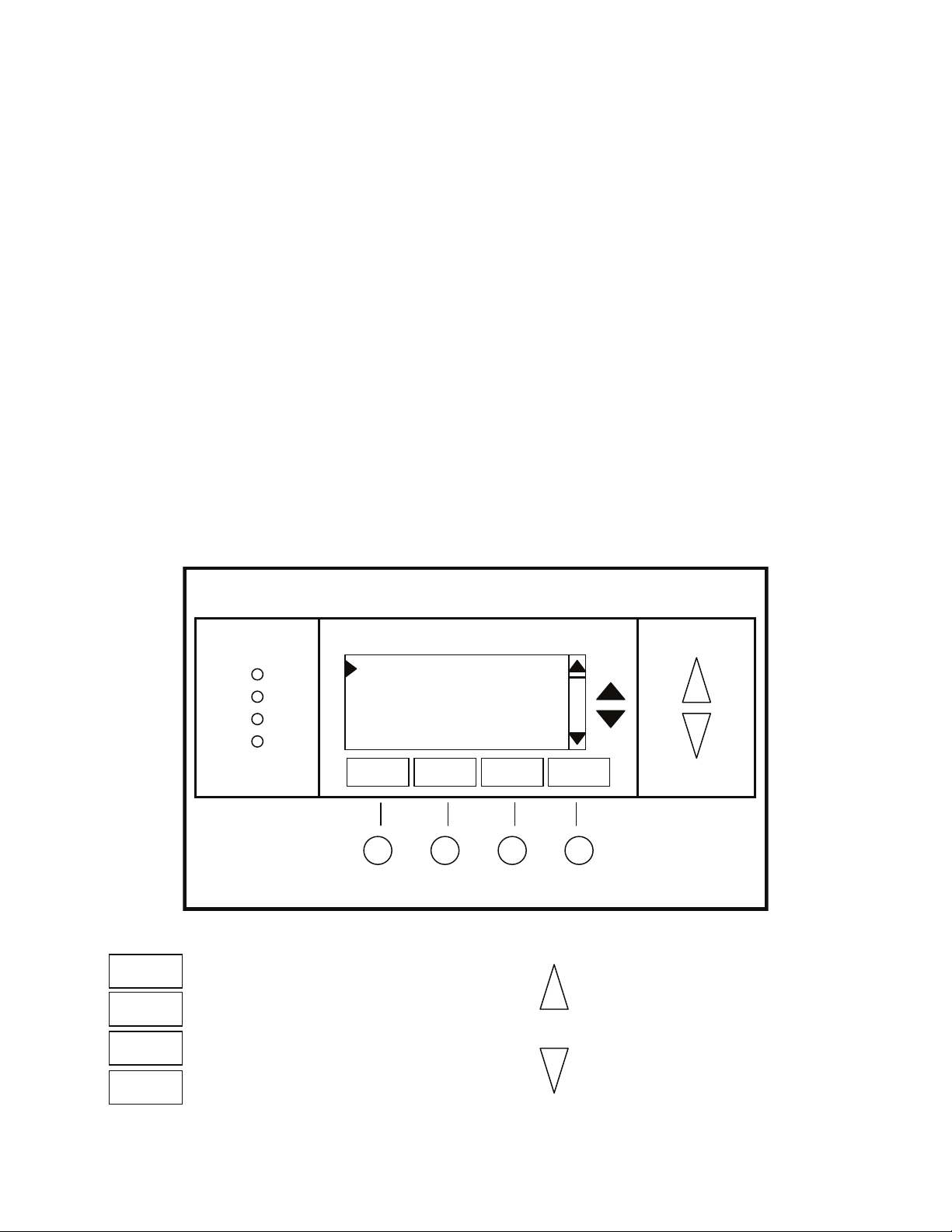
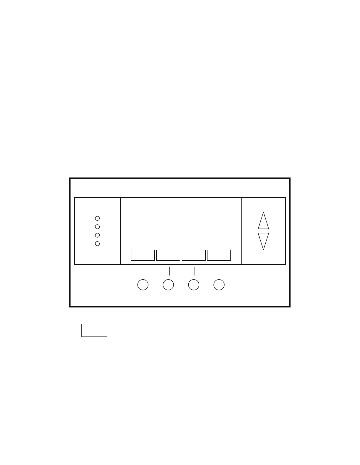
Thermostat Screens
A unique feature of the Thermostat graphical display is the ability to have multiple display screens. In addition to a main
thermostat control screen, menus and other control screens for special functions are provided. This makes an intuitive
and easy to use “user interface”. It allows the many functions of the Thermostat to be easily navigated.
The main screen is the Thermostat Control Screen. From this screen you can access a menu screen that will list other
control screens or setup screens.
Thermostat Control Screen
This is the thermostats default screen and the only screen needed for basic thermostat operation (temperature setting
and heat/cool mode selection). All other screens will automatically timeout and return this screen after 120 seconds of no
activity.
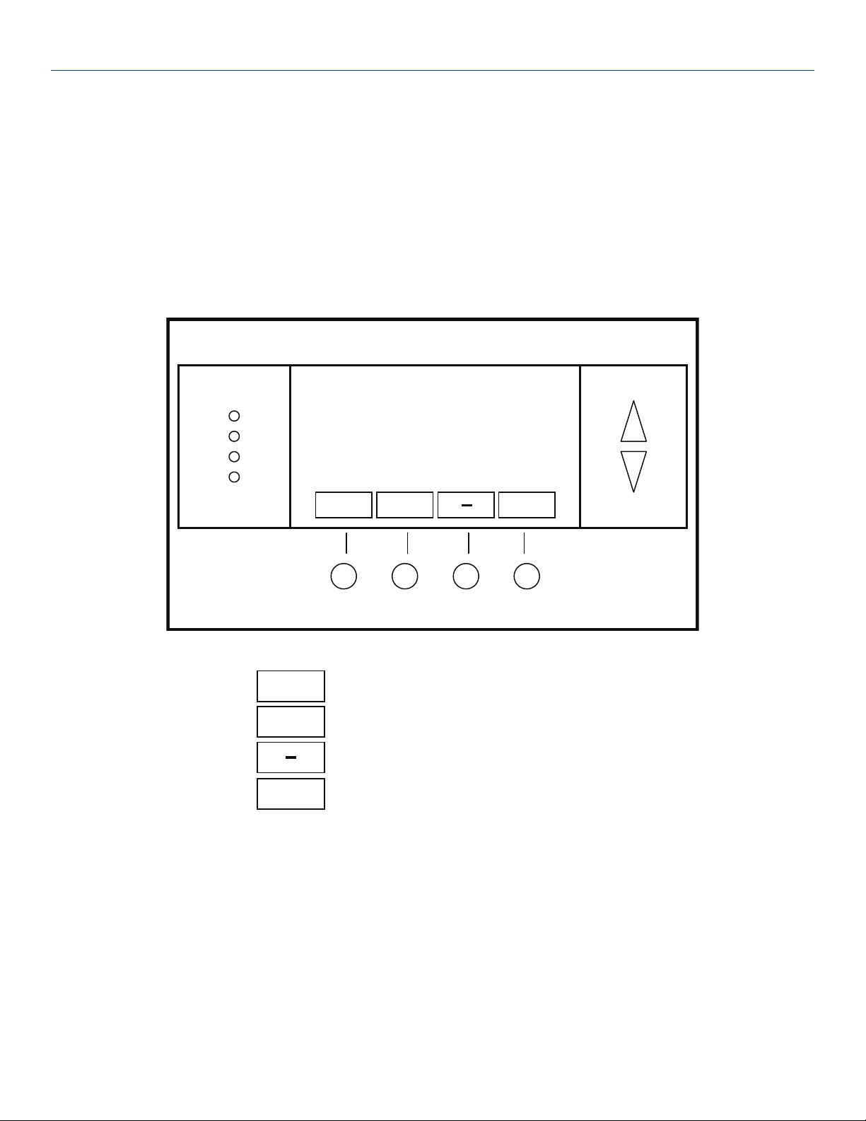
Minimized Thermostat Screen
(This feature is disabled by default. See page 16, Screen Timeout for more information)
The main thermostat screen will go to a “minimized” screen after a 30 second timeout period. This presents a simple
uncluttered display of the current room temperature.
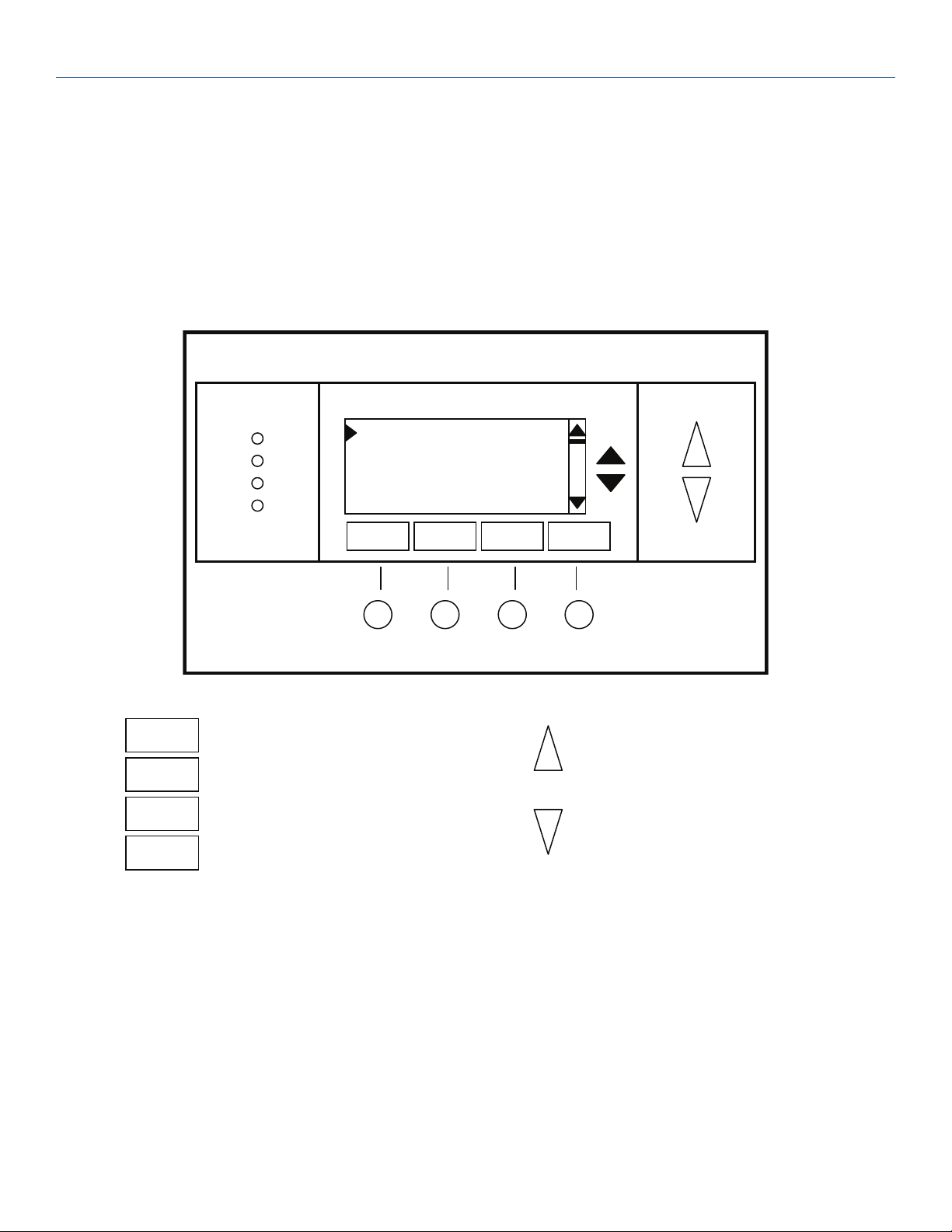
Menu Selection Screen
Pressing the Menu button on the Thermostat Control Screen will go to the Menu Selection screen. This screen presents a
list of the other functions or setup screens that can be selected.
Schedules Screen
(Optional screen) Only shows up in the Menu Selection list if local scheduling is enabled. (See Installer Settings, then
System Settings Menu and then Schedule Enable on page 23).
This screen is used to view and edit the time based setback schedules for the thermostat.
5
Page 6

Thermostat User Guide
User Settings Screen
This screen is a submenu of user settings for the initial setup of the thermostat. You can set the clock, minimized screen
timeout, Fahrenheit or Centigrade selection, sensor calibration and display settings.
Usage Graph
Shows daily heating and cooling runtime hours for a week.
ESM Setpoints
This screen is a submenu of the Energy Savings Mode settings. You can set the heating and cooling setpoint setback
temperatures. These settings are used when the thermostat is in the ESM mode.
ZWave Install
This screen is a submenu for installing the thermostat into a Z-Wave network. When the Z-Wave network controller is
ready to install the thermostat, press the YES button to install.
Thermostat Info Screen
This is a quick reference list of the thermostat firmware versions, Z-Wave network addresses and HVAC system setup.
6
Page 7

Thermostat Control Screen
72
MODE
FAN
MENU
77 H
Sys Off
Run
Filter
10:25 AM
RUN
74 C
The main Thermostat Control Screen is the default display screen and is the screen that is normally displayed on the
Thermostat.
Temperature Display
The Thermostat will display the current temperature from the internal temperature sensor.
Setpoint Display
The heating and cooling setpoints are displayed next to the Setpoint Up/Down buttons. In the HEAT mode, the Up/Down
buttons change the heat setpoint. In the COOL mode, they change the cooling setpoint. When in AUTO mode, the buttons
change the last call’s heating or cooling setpoint. Note that the setpoints will “push” each other if they are adjusted to get
within the minimum Heat/Cool separation setting. This is normally 3 degrees.
Clock Display
The current time is displayed in the upper left corner of the main screen. Set the clock from the User Settings Menu.
The time will blink when the clock has not been set.
7
Page 8

Thermostat User Guide
72
Done
HEATING SETPOINT
Heating
and
Cooling
Setpoint
setting
buttons
Up
Down
Thermostat Control Screen Buttons
Setpoint Up and Down Buttons
Pressing the Up or Down button in the main Thermostat Control Screen will take you to the Heating Setpoint or Cooling
Setpoint screen, as shown below.
The UP and DOWN buttons adjust the setpoint temperature. Pressing the UP button will increment the setpoint value by
one degree and conversely, pressing the Down button will decrement the setpoint one degree. Pressing and holding a
button down will cause the setpoint to continuously change until the button is released.
Setpoint Range: The setpoints can be set from 55°F to 90°F (12°C to 32°C) for Heating or 60°F to 99°F (15°C to 37°C)
for Cooling.
Setpoint Push: Note that you cannot lower the cooling setpoint below the heating setpoint. The thermostat will push
the heating setpoint lower if you try to lower the cooling below the heating setpoint. It maintains a 3 degree separation
between the heating and cooling setpoint. The same is true for raising the heating setpoint above the cooling setpoint.
Again the thermostat will “push” the cooling setpoint up to maintain the 3 degree separation.
NOTE: If the system mode is OFF, pressing the setpoint Up or Down buttons will take you to the system mode
screen. You must set the mode to an operating mode before you can change the setpoints.
To change the Heat Setpoint you must be in Heat mode, to change the Cool Setpoint you must be in the Cool
mode.
If you are in Auto mode when you press the Up or Down buttons, you will go to the last call’s mode, heating or
cooling, setpoint setting screen.
12
Page 9

MENU Button
RUN
AUTO
FAN
OFF
MODE
MENU
MENU Button
The Menu button changes the screen display to the MAIN MENU screen which show what other functions are available on
the Thermostat. These are dynamic and can change with the version of the thermostat you have, but the standard ones
include:
Main Thermostat Screen
Menu Button
Menu Selection Screen
User Settings
Usage Graph
ESM Setpoints
ZWave Install
Thermostat Info
12
Page 10

Thermostat User Guide
OFF
HEATING
COOLING
AUTO
EHEAT
Done
SYSTEM MODE
Use the Up/Down
buttons to scroll
through the
Mode
MODE Button
The MODE button controls the HVAC system mode. The current mode selected is displayed above the button. Pressing
the MODE button will take you to the System Mode screen.
Pressing the Up or Down buttons will scroll through the mode options. Pressing done or waiting for the screen to timeout
will select the new mode.
System Mode Screen
Mode Operation
Off Mode: System is off. No heating or cooling will come on. If system was on, it will turn off.
Heat Mode: Only heating will occur.
Cool Mode: Only cooling will occur.
Auto Mode: Heating or cooling will come on according to the heating and cooling setpoints. The system will automatically
switch between heating and cooling when the temperature exceeds the appropriate setpoints.
EHEAT Mode: Emergency Heat mode is only displayed when Heat Pump HVAC System Type is selected. During extreme
weather conditions or when there is a compressor failure with the heat pump system, setting the mode to EHEAT will
allow the supplemental heat to come on whenever there is a heat call to provide heating and also disables the compressor
outputs.
12
Page 11

FAN Button
AUTO
ON
CYCLE*
Done
FAN MODE
Use the Up/Down
buttons to scroll
through the
FAN
HOLD
RUN
ENERGY SAVING MODE
Done
SCHEDULE MODE
Use the Up/Down
buttons to scroll
through the
RUN
FAN Button
The FAN button controls the HVAC system’s MANUAL fan. The current manual fan mode is displayed above the button.
Pressing the FAN button will take you to the FAN MODE screen shown below.
Fan Mode Screen
Normally the FAN mode is in the Auto mode (the system fan is automatically controlled by HVAC system). If you want the
FAN on manually, select the ON mode. The fan will run continuously until it is turned to off by selecting AUTO mode.
NOTE: If the Fan Cycler feature is enabled in the Installer Setup, the additional fan mode “Cycle” will be available.
This mode cycles the fan on and off per the settings for fresh air ventilation.
RUN/HOLD/ESM Button
The RUN/HOLD/ESM button controls the automatic SCHEDULE operation. Pressing this button will take you to the
SCHEDULE MODE screen as shown below.
Run/Hold/ESM Screen
Run Mode. In the run mode, the thermostat schedule is running and setpoints will change according the times and
temperatures in the schedule. The schedule can be local (if enabled in the Installer Settings) or remote via the Z-Wave
network.
Hold Mode. This holds the current temperature setpoint settings. The schedule operation is inhibited.
Energy Savings Mode (ESM). This is a setback mode. When selected, the ESM temperature setpoint settings are used.
It also inhibits schedule operation.
12
Page 12

Thermostat User Guide
LED Displays
The Thermostat Control Screen has the following LED and on-screen labels numbered from top to bottom.
LED 1 Green: System Operation display•
Sys Off• displayed = HVAC system is OFF; LED Off.
WAIT• displayed = Minimum Off Time (MOT)delay is active; LED Off (Note: See pages 25 and 30 for more
information on the Minimum Off Timer)
Cool On• displayed = Cooling system is running; LED On.
Cool On• displayed = Cooling Min Run Time (MRT); LED On. (Note: See pages 25 and 30 for more information on
the Minimum Run Timer)
Heat On• displayed = Heating system is running; LED On.
Heat On• displayed = Heating Minimum Run Time (MRT); LED On. (Note: See pages 25 and 30 for more
information on the Minimum Run Timer)
LED 2 Green: System Stage display•
No display = 1st stage heating or cooling. LED Off.•
2nd Stg• displayed = Stage 2 heating or cooling is active. LED On.
Aux Heat• displayed = Stage 3 heating is active. LED On.
LED 3 Green: Run/Hold/ESM display. Shows state of Schedule Run/Hold Mode.•
Run• displayed = Schedule mode is active. LED Off.
Hold• displayed = Temperature hold is active. LED On.
ESM• displayed = (Energy Savings Mode) Temperature preset is active. LED On.
LED 4 RED: Alert LED. Used for other system alerts•
No display = No alerts or messages. LED Off.•
Filter• displayed = Filter run timer reached. LED On.
Maint• displayed = Maintenance run timer reached. LED On.
12
Page 13
Main Menu
Menu Selection
User Settings
Usage Graph
ESM Setpoints
ZWave Install
Select
Done
Return to Thermostat Screen
Not used
Not used
Select menu item at pointer
Select
Move menu selection pointer up
Move menu selection pointer
The Thermostat has a menu tree that can be accessed by pressing the “Menu” button on the Main Thermostat screen.
Various configurations of the Thermostat can have different screen contents. The first screen that will come up is the
Menu Selection screen. This is a list of the other menus or functions that can be accessed.
Schedules Screen. (Optional Screen) Only shows up in the Menu Selection list if scheduling is enabled. (See Installer
Settings, then System Settings Menu and then Schedule Enable on page 23). This screen is used to view and set the
programmable setback schedules of the thermostat.
User Settings Screen. This screen is used to set the Clock, Filter Service and Maintenance Service, Screen Timeout,
Fahrenheit/Celsius settings, Sensor Calibration and Backlite/Display settings.
Usage Graph. Shows daily heating and cooling run time hours for a week.
ESM Setpoints. Used to set the Energy Savings Modes heating and cooling setpoints.
ZWave Install. Used to install the thermostat into a ZWave network.
Thermostat Info Screen: This screen shows the firmware versions of the Thermostat and Zwave interface, HVAC system
type and equipment options.
Main Menu
Screen navigation buttons:
13
Page 14

Thermostat User Guide
Select Schedule
Heat and Cool
Preset: Comfort
Preset: Energy Star
Select
Done
Select
Return to Main Menu Screen
Select the schedule to view or modify
Move menu selection pointer up
Move menu selection pointer
Schedules
Schedules is an optional menu item. It will only show up in the menu list if “Schedules” is enabled in the Installer settings
for the thermostat (See page 23). Provides for local schedule control. The Schedules Screen allows you to review and
set the setback schedule for the thermostat. The thermostat has a 4 x 7 schedule. Four times a day can be selected for
changes to the heating and cooling setpoints. Each day of the week can have a different schedule. Groups of days can
be copied with the same schedule. When the thermostat is set to “Run” mode, the schedule will be executed daily, with
the setpoints being changed as per that days schedule stored in the thermostat. “Hold” mode stops schedule operation
and holds the current setpoints until changed manually or by network commands.
The Schedules Screen gives you the option of setting a custom setback schedule or to load one of two preset schedules.
Menu Options
• HeatandCool:Youcanchangetheindividualday/hourandsetpointsfortheHeatingandCoolingscheduleby
selecting this menu item.
• Preset:Comfort:Thisisapresetschedulewithmildsetbacks.SelectthismenuitemtoloadtheComfort
schedule into the thermostat.
• Preset:EnergyStar:Thisisapresetschedulewithdeepersetbacks.SelectthismenuitemtoloadtheEnergy
Star schedule into the thermostat.
Schedules Screen
Screen navigation buttons:
27
Page 15

Heat and Cool Schedules
Monday
Time Heat Cool
Morn 6:00 A 72 82
Day 9:00 A 68 84
Eve 5:00 P 74 76
+
_
c
Done
Next
Copy
Return to Main Menu Screen
Scroll Back
Scroll Forward
Select the next Day schedule
OR if the copy “c” is selected,
+ Increment time or temperature
- Decrement time or temperature
Heat and Cool Schedules
When you select the Heat and Cool Schedule menu item, the “day” Schedule programming screen opens and the
schedule for current day will be displayed. Use the scroll buttons to highlight the data to be modified. Once the data has
been highlighted, use the +/- buttons to change the value of the data.
To copy a days schedule to another day or group of days, move the cursor to “c” on the bottom right of the schedule
screen. When you highlight the “c”, the button below will become “Copy”. Press this button to change to the Copy
Schedule Screen.
Schedule Screen
Screen navigation buttons:
27
Page 16

Thermostat User Guide
Copy Monday Schedule
to
Sun Tue Wed Thu Fri
Sat
Copy
Yes
No
Return to Schedule Screen
Move back with selection bar
Move forward with selection bar
Copy the schedule to the selected days
Back
Copy
Yes - Copy schedule to this day
No - Do not copy to this day
Copy Schedule
The Copy Schedule screen is a sub screen of the Schedule screen. The Copy Schedule screen allows you to copy a day’s
schedule to another day or group of days.
First select the day to be copied in the Schedule screen. Scroll to the “c” at the bottom of the Schedule screen to highlight
it. The “Next” button will change to the “Copy” button. Press the “Copy” button to open the Copy Schedule screen.
Scroll through the days and select the days you want to copy the schedule to by setting the “N” under each day to “Y” by
using the Yes/No buttons.
After selecting all the days desired, press the “Copy” button.
Exit the Copy Schedule screen with the “Back” button.
Copy Schedule Screen
Screen navigation buttons:
27
Page 17

User Settings
User Settings
Set Clock
Filter Service
Maint Service
Screen Timeout 0
Select
+
_
Done
Select
Return to Main Menu
Increment value
Decrement value
Select the function to be set
_
Move menu selection pointer up
Move menu selection pointer
User Settings
The User Settings screen allows you to set or change various user options of the thermostat such as the Clock, Minimized
Screen timeout, Fahrenheit/Celsius mode, Sensor Calibrations, and Display settings.
Menu options:
Set Clock: Select this menu item to go to the Clock setting screen.•
Filter Service: Sets/resets the filter timer/alert.•
Maint Service: Sets/resets the maintenance timer/alert.•
Screen Timeout: Select the Screen Timeout time in seconds. Options are 0 or 20 to 120 (default set to 0 seconds). •
This is the time before any screen reverts to the Minimized Screen (temperature display only), after you stop
pushing buttons. Minimized Screen feature is disabled by setting this time to “0”.
F/C Mode: Select which temperature display mode you desire, Fahrenheit (F) or Celsius (C).•
Sensor Calibration: Select this menu item to go to the Sensor Calibration screen. •
Backlite/Display: Select this menu item to go the Backlite/Display settings screen. This menu allows you to set the •
backlight timeout period and adjust the display contrast.
User Settings Screen
27
Page 18

Thermostat User Guide
Set Clock
Time 12:00 PM
Date 7/13/08
Day Thu
Back
+
_
Cancel and return to User Settings Menu
Move back with selection box navigation arrow
Move forward with selection box navigation
Back
Set
+ Increment selected item
-
Decrement selected item
Set Clock
The Set Clock screen allows you to set the Thermostat’s internal clock.
To set the Time and Date, move the cursor with the navigation arrows until the data you want to change is highlighted.
Using the + and – buttons to increment or decrement the data to the desired setting.
When finished, press the SET button to return to the Main Menu screen or wait for screen to timeout.
NOTE: If the clock has been reset by an extended power outage, the Clock display on the thermostat screen will be
blinking. Pressing the MENU button will take you directly to this screen to set the clock.
Set Clock Screen
Screen navigation buttons:
27
Page 19

Filter Service
Filter Service
Filter Runtime
Service Interval
12 HRS
300 HRS
Done
Reset
+
Return to Main Menu Screen
Increase the Service Interval by 1
hour
Decrease the Service Interval by 1
Filter Service
The Filter Service screen will show the accumulated Filter Runtime hours as well as the Service Interval that will be used
to trigger a Filter Message. Any type of HVAC operation that causes the HVAC system fan to run will cause the Filter
Runtime value to increase.
When the Runtime hours equals the Service Interval hours, the Red LED will flash along with a “Filter” message to remind
you to replace the filter. Pressing the Menu button will take you to the Filter Service screen. Once the filter has been
replaced, press the Reset button to reset the Filter Runtime value to zero.
The Service Interval period can be changed using the +/- buttons.
Filter Service Screen
Screen navigation buttons:
27
Page 20
Thermostat User Guide
Maintenance Service
Heat Runtime
Service Interval
0 HRS
3000 HRS
Cool Runtime
0 HRS
Done
Reset
+
Return to Main Menu Screen
Increase the Service Interval by 1
hour
Decrease the Service Interval by 1
Maint Service
The Maintenance Service screen will show the accumulated Heat and Cool Runtime hours as well as the Service Interval
that will be used to trigger a Maintenance Message. Any HEAT or COOL type of HVAC operation will cause the respective
Runtime values to increase.
When the combined HEAT and COOL Runtime hours equals the Service Interval hours, the Red LED will flash along with
a “Maint” message to remind you your HVAC system may require periodic maintenance. Pressing the Menu button will
take you to the Filter Service screen. The Reset button can be pressed and the HEAT and COOL Runtime values will be
reset to zero.
The Service Interval period can be changed using the +/- buttons.
Maintenance Service Screen
Screen navigation buttons:
27
Page 21

Sensor Calibration
Sensor
Internal (75) 1
Done
+
Return to Main Menu Screen
Increase the temperature by 1 deg
Decrease the temperature by 1 deg
Sensor Calibration
The Sensor Calibration screen allows you to change the temperature calibration of the internal temperature sensor. You
can change the temperature calibration by +/- 7 degrees.
When the Sensor Calibration screen is selected it will show the current temperature calibration (The (75) in the example
screen below) and the current number of degrees of offset being applied (1 deg in the example). If the sensor’s actual
temp is (74) with 0 degrees of offset and you want it to be 75, then press “+” to add 1 deg and it will show (75).
To change the temperature calibration, use the scroll buttons to select the internal or a remote sensor. Once selected, use
the + and – buttons to change the temperature calibration to the desired setting.
The value shown in the (xx) is the calibrated or offset temperature that you want the sensor to show.
When you close this screen, it may take a few seconds for the temperature displayed on the main thermostat screen to
update to the new temperature.
Sensor Calibration Screen
Screen navigation buttons:
27
Page 22
Thermostat User Guide
Backlite/Display
Backlite Timeout 30
Contrast 10
+
_
Done
Return to User Settings menu
Increment value
Decrement value
_
Move menu selection pointer up
Move menu selection pointer
Backlite/Display
The Backlite/Display screen allows you to set the Backlite timeout and contrast.
Backlite Timeout: Sets the time from last button press that the backlite will timeout and turn off. The timeout value is
adjustable from 0 or 20 to 120 seconds. If set to “0”, the Backlite will always be ON. If set in the range of 20 to 120
seconds, the Backlite will turn OFF after the selected time expires.
Contrast: Sets the contrast level of the LCD display, adjustable from 0 to 20. Use this control to adjust the darkness of the
display. To light and the display looks faded, too dark and dark lines will appear in the display. Typically 10 is the correct
setting. Adjust as needed.
Backlite Settings Screen
Screen Navigation Buttons
27
Page 23
Thermostat Info
Thermostat Info
TZEMT400AB32 Ver: 01.00.00
ZVER:01.02.2 ZNID: 002
ZHID: 00.00.50.12
System Type: Standard
Done
Return to Main Menu screen.
Thermostat Info
The Thermostat Info screen displays the current configuration of the Z-WAVE Thermostat. This information is useful for
quick check of firmware versions and HVAC system setup. It also shows the Zwave network setting.
Thermostat information displayed is:
Thermostat - Model and firmware version number.•
Z-Wave Settings - ZWave Firmware version, ZWave Node ID, ZWave Home ID•
System Type - Standard or Heatpump HVAC system•
Fan Type - setting for Standard systems: Gas or Elect •
OR
Changeover - setting for Heat Pump systems: Changeover with cool or changeover with heat. •
When finished viewing this screen press the Done button to return to the main Menu screen or wait for screen to timeout.
Thermostat Info Screen
Screen navigation buttons:
27
Page 24

Thermostat User Guide
Installer Settings Menu (Hidden Screen)
The Installer Settings screen is a hidden screen designed for installer use only. Do not change any settings in this screen
unless you are a qualified service technician. Changing these settings will affect the operation of the heating/cooling
system.
To enter this screen, go to the main menu selection screen and press and hold the two inner buttons for 3
seconds until the Installer Settings screen appears.
The Installer Settings screen displays the current internal settings of the thermostat. You can view and change the
settings from this screen. Scroll to the desired function and use the +/- buttons to change.
Display Lock: Range: Y or N Default: N
Y = Display LOCKED
N = Display unlocked
Allows you to lock or unlock the thermostat buttons. When the buttons are locked, you can still access the main menu, but
you will not be allowed to select any menu options. The Installer Settings hidden button operation is always operational,
allowing you to return to this screen and turn Display Lock off.
System Settings Menu
Mechanical Settings Submenu
Type Range: Gas/Elec or Heatpump Default: Gas/Elec
Selects HVAC type, Gas/Electric or Heatpump
Fan Type Range: Gas or Elec Default: Gas
Selects the Fan type if system is Gas or Electric
C/O Type Range: w/Cool or w/Heat Default: w/Cool
Set the Heat pump Changeover type
2nd Stage Heat Range: Y or N Default: N
Enables the 2nd Stage Heat operation
Aux Heat (HP) Range: Y or N Default: Y
Enables the Auxiliary Heat operation. Typically the Aux Heat will be heat-strips in a Heatpump system
2nd Stage Cool Range: Y or N Default: N
Enables the 2nd Stage Cool operation
Schedule Enable Range: Y or N Default: N
When enabled, the local thermostats scheduler function is enabled.
Note on Delta Settings: The Delta T Setting is the delta, or difference between, the setpoint and current temp for
determining when a heat or cool call comes on. The “delta” is the number of degrees away from setpoint.
27
H/C Delta Range: 3 - 15 degrees. Default: 3
Sets the minimum separation between heating and cooling setpoints. Attempts to lower the cooling below the
heating setpoint by this amount will PUSH the heating setpoint down to maintain this separation. Same for setting
the heating setpoint above the cooling setpoint, it will PUSH the cooling setpoint up to maintain this separation.
Heating Delta Stage 1 ON Range: 1 to 8 degrees Default: 1
Sets the delta from setpoint that stage 1 heating starts.
Heating Delta Stage 1 OFF Range: 0 to 8 degrees Default: 0
Sets the delta from setpoint that stage 1 heating stops. Stage 1 turns off at setpoint + Delta Stage 1.
Page 25

Installer Settings Menu (Hidden Screen)
Heating Delta Stage 2 ON Range: 1 to 8 degrees Default: 2
Sets the delta from setpoint that stage 2 heating starts.
Heating Delta Stage 2 OFF Range: 0 to 8 degrees Default: 0
Sets the delta from setpoint that stage 2 heating stops. Stage 2 turns off at setpoint + Delta Stage 2.
Heating Delta Stage 3 ON Range: 1 to 8 degrees Default: 3
Sets the delta from setpoint that stage 3 heating starts.
Heating Delta Stage 3 OFF Range: 0 to 8 degrees Default: 0
Sets the delta from setpoint that stage 1 heating stops. Stage 3 turns off at setpoint + Delta Stage 3.
Cooling Delta Stage 1 ON Range: 1 to 8 degrees Default: 1
Sets the delta from setpoint that stage 1 cooling starts.
Cooling Delta Stage 1 OFF Range: 0 to 8 degrees Default: 0
Sets the delta from setpoint that stage 1 Cooling stops. Stage 1 turns off at setpoint - Delta Stage 1.
Cooling Delta Stage 2 ON Range: 1 to 8 degrees Default: 2
Sets the delta from setpoint that stage 2 cooling starts. Stage 2 turns off at setpoint.
Cooling Delta Stage 2 OFF Range: 0 to 8 degrees Default: 0
Sets the delta from setpoint that stage 2 Cooling stops. Stage 2 turns off at setpoint - Delta Stage 1.
Max Heat SP Range: 55F to 90F (12C-32C) Default: 90F (32C)
Sets the maximum heating setpoint value. Will not ramp or accept setpoints higher that this maximum.
Min Cool SP Range: 60F to 99F (15C-37C) Default: 60F (15C)
Sets the minimum cooling setpoint value. Will not ramp or accept setpoints lower than this minimum.
Minimum Run Time (MRT) Range: 1- 9 Minutes Default: 3
Sets the minimum run time before a heating/cooling cycle can turn off.
Sets heating/cooling cycle time. Prevents rapid cycling.
Thermostat screen will display “Cool ON” or “Heat ON” while the minimum run time is being enforced.
Minimum Off Time (MOT) Range: 5-9 Minutes Default: 5
Sets the minimum off time before another heating/cooling cycle can begin. Provides compressor short cycle protection.
Thermostat screen will display “WAIT”.
Fan Cycler Submenu
The fan cycler function cycles the HVAC system fan for an ON period followed by an Off period continuously. Used to
provide minimum air ventilation requirements. When the Fan ON time is set to a value greater than 0, an additional
“Cycler” FAN mode is present when pressing the FAN button.
Fan ON Time Range: 0-120 minutes Default: 0 (=OFF)
Fan OFF Time Range: 10-120 minutes Default: 10
27
Page 26

Thermostat User Guide
Installer Settings Summary
Setting Range Default
Display Lock Y or N N Locks out front buttons
F/C Mode C or F F
Screen Timeout 0-240 0 seconds
Schedule Enable Y or N N
Max heat setpoint 55F-90F (12C-32C) 90F (32C)
Min cool setpoint 60F-99F(15C-37C) 55F (15C)
Min Run Time (MRT) 1 – 9 3
Min Off Time (MOT) 5 – 9 5
Mechanical - Type Std or HP Std
Mechanical - Fan Type Gas or Elec Gas
Mechanical - C/O Type w/Heat or w/Cool w/Cool
Mechanical - 2nd Stage
Heat
Mechanical - Aux Heat Y or N Y
Mechanical - 2nd Stage
Cool
Y or N N
Y or N N
Filter Interval 300
Maint Interval 3000
H/C Delta 3 – 15 3
Heat Delta Stage 1 On 1 – 8 1
Heat Delta Stage 1 Off 0 – 8 0
Heat Delta Stage 2 On 1 – 8 2
Heat Delta Stage 2 Off 0 – 8 0
Heat Delta Stage 3 On 1 – 8 3
Heat Delta Stage 3 Off 0 – 8 0
Cool Delta Stage 1 On 1 – 8 1
Cool Delta Stage 1 Off 0 – 8 0
Cool Delta Stage 2 On 1 – 8 2
Cool Delta Stage 2 Off 0 – 8 0
Fan Cycler ON time 0 – 120 0 0 = Fan Cycler OFF
Fan Cycler Off Time 10 – 120 10
27
Page 27

Installer Settings Screen
Installer Settings
Display Lock N
System Settings
Max Heat SP 90
Min Cool SP 55
Select
+
Done
Selec
+
Return to Main Menu screen
Increase by 1 or change from N to Y
Decrease by 1 or change from Y to N
Select menu item to go to a submenu
Move menu selection pointer up
Move menu selection pointer down
Screen navigation buttons:
Installer Settings Summary
27
Page 28

HVAC System Connection
The thermostat connects to the HVAC system’s thermostat connections just like a traditional thermostat does.
HVAC System Compatibility
The thermostat is compatible with most heating and cooling systems. There are two types of HVAC systems: Standard
(gas/electric) and Heat Pump systems. The system type is selectable from the Installer Screen – System Settings –
Mechanical Settings submenu.
For Standard HVAC systems: Gas heating or Electric heating.
For Heat Pump HVAC systems: supports changeover valve operation for either changeover with cooling or changeover
with heating.
Multi-Stage HVAC Compatibility
For Standard HVAC systems, the HVAC outputs support 2 stages of heating and 2 stages of cooling.
For Heat Pump HVAC systems, the HVAC outputs support 3 stages of heating (2 compressor/1 Aux Heat) and 2 stages of
cooling.
Dual Fuel
NOTE: This thermostat is not compatible with dual fuel systems, without a dual fuel kit. (Heating system with
both heat pump and gas furnace.) If you need a dual fuel kit, please contact a qualified heating and cooling
contractor.
Remote Communications
The Z-WAVE thermostats have a Z-Wave communications module for communicating to control systems with Z-Wave
capability.
28
Page 29

Standard Gas/Electric HVAC System Wiring
RED
GREEN
WHITE
YELLO W
Z-WAVE Thermostat
W1 HEAT
JP1: internal RC/RH Jumper
See notes
24RC
ORANGE
BROWN
24RH
G FAN
W2/O
Y1 COMP
Typical HVAC system
thermostat wiring color
codes.
Be sure to verify your
Y2 COMP
24COM
Standard HVAC System
G Fan
W 1 Heat Stage 1
Y1 Compressor Stage 1
R 24VAC RETURN
C 24VAC COMMON
THERMOSTAT CONNECTION
Y2 Compressor Stage 2
W2 Heat Stage 2
BLUE
Standard Gas/Electric HVAC System Wiring
Installation Notes
Standard HVAC System Setup
System Type: Set the system type to Gas/Elect in the Mechanical Settings menu of the Installer Setup. This is the default
setting.
Single Stage systems use W1 for heating stage 1 and Y1 for cooling stage 1.
Two Stage Heating systems use W1 for stage 1 and W2 for stage 2 heating.
Two Stage Cooling systems use Y1 for stage 1 and Y2 for stage 2 cooling.
HVAC system transformer: If you have an integrated heating and cooling system with a single transformer, do NOT cut
jumper JP1. Wire the HVAC system’s 24VAC common (blue wire) to the 24Com terminal and the 24VAC Return (red) wire
to either 24RH or 24RC terminal. This is typical of most central systems.
If you have separate heating and cooling systems with separate transformers, cut jumper JP1. Wire the heating 24V R
(red) wire to the thermostat’s 24RH terminal. Wire the cooling systems 24V R (red) wire to thermostat’s 24RC terminal.
Also wire the cooling systems 24VAC Common (blue wire) to the thermostat’s 24COM terminal.
30
Page 30

Thermostat User Guide
RED
GREEN
WHITE
YELLO W
Z-WAVE Thermostat
W1 HEAT
JP1: internal RC/RH Jumper
Do not cut for HP systems
24RC
ORANGE
BROWN
24RH
G FAN
W2/O
Y1 COMP
Typical HVAC system
thermostat wiring color
codes.
Be sure to verify your
Y2 COMP
24COM
Heat Pump HVAC System
G Fan
W 1 Aux Heat
Y1 Compressor Stage 1
R 24VAC RETURN
C 24VAC COMMON
THERMOSTAT CONNECTION
Y2 Compressor Stage 2
Change Over Valve
BLUE
Heat Pump HVAC System Wiring
Installation Notes
Heat Pump HVAC System Setup
System Type: Set the mechanical system type to Heat Pump in the Installer Settings Menu
Single Stage Compressor Systems use Y1 for stage 1 heating/cooling, and W1 for stage 2 Aux Heating.
Two Stage Compressor Systems use Y1 for stage 1, Y2 for stage 2 heating/cooling, and W1 for stage 3 Aux Heating.
Change Over Valve: You must configure the thermostat’s changeover valve setting to work correctly with your HVAC
system. Check your system information to be sure.
Changeover settings are made in the Installer Settings – System Settings - Mechanical Settings menu. •
Changeover with cool is the default setting and typical for most systems. •
If you get cooling when you expect heating, change the C/O type to the opposite setting.•
HVAC system transformer: Heat pump systems have one system transformer. Do not cut the RC/RH jumper. Wire the
HVAC systems 24VAC common (blue wire) to the 24Com terminal, and the 24VAC return (red wire) to the 24RC terminal.
30
Page 31

HVAC System Operation and Setup
General Heating and Cooling Operation
In the HEATING mode, the heating system will be turned on at one degree below the setpoint and will turn off at the
setpoint. This turn on and turn off offset is referred to as the heating setpoint “delta T” and is adjustable in the Installer
Settings menu of the THERMOSTAT. It is set to the one degree operation by default.
In the COOLING mode, the cooling system will be turned on at one degree above the setpoint and will turn off at the
setpoint. Similarly, the cooling setpoint delta T is adjustable in the Installer Settings menu.
In the AUTO mode, the system will switch between heating and cooling as determined by the heating and cooling
setpoints and the current temperature. Once in a heating or cooling mode of operation, the normal one degree setpoint
control is maintained.
Setpoint Push. Heating and cooling setpoints are forced to maintain a separation between them, with a default setting
of 3 degrees. If the heating or cooling setpoint is changed to be within the setpoint delta, the system will automatically
“push” the other setpoint to maintain the setpoint delta separation. The H/C setpoint delta is also adjustable in the Installer
Settings menu of the THERMOSTAT.
Standard HVAC System Types
Gas or electric heating systems are considered “Standard” HVAC systems. These systems consist of an indoor furnace/
blower assembly and an outdoor AC condensing unit (for those systems with air conditioning installed). These systems in
general are referred to as central forced air HVAC systems.
You must configure the Thermostat to match your HVAC system type for correct system operation.
Setup
Standard System Type Selection
To configure the Thermostat for standard Gas/Electric HVAC system operation, change the Type in the Installer Settings –
System Settings – Mechanical Settings menu option to Gas/Elec.
Fan Type Selection
Gas systems typically do not require a fan output for heating operation. Set the Fan Type in the Installer Settings –
System Settings – Mechanical Settings – Fan Type to GAS.
Electric (and hydronic) heating systems typically do require a fan output with the call for heating. Set the Fan Type in the
Installer Settings – System Settings – Mechanical Settings – Fan Type to ELEC.
Be sure to check your HVAC system’s requirements.
Heat Pump HVAC System Types
Heat Pump HVAC systems are combined heating and cooling systems. The system consists of an indoor “air handler” (a
blower fan and coil assembly) and an outdoor unit. Heat pumps change from heating mode to cooling mode by switching
the refrigerant flow using a “changeover” or “reversing valve”. In both heating and cooling operation the compressor and
fan outputs are on and the state of the changeover output determines if heating or cooling is being provided. Heat pumps
can have one or two stages of compressor operation plus an optional third stage of electric heat strips.
31
Page 32

Thermostat User Guide
The third stage of heating will be turned on when the current temperature falls 3 deg below the current setpoint and will
turn off at the setpoint.
Setup
Heat Pump System Type Selection
To set the Thermostat for Heat Pump HVAC operation, change the Type in the Installer Settings – System Settings –
Mechanical Settings menu option to Heatpump.
Changeover Type Selection
Most heat pump systems are designed to work normally in the heating mode and require a change over output for cooling
output. Change the C/O Type in the Installer Settings – System Settings – Mechanical Settings menu option to match your
system needs.
Changeover with Cooling: Set C/O Type to w/Cool (This is the default setting).
Changeover with Heating: Set C/O Type to w/Heat.
Note: During Heat Pump operation the changeover relay, once engaged, will stay on until the opposite HVAC call
occurs.
Check your HVAC system requirements for correct settings.
Minimum Run Time (MRT)
The thermostat has a Minimum Run Time after the start of any heat or cool call. This minimum run time assures even
heating and cooling cycles. Minimum Run Time will keep the system on even if you change the setpoint to a temperature
that would satisfy the call, until the MRT expires. Changing the Mode to OFF will cancel the MRT and the system will turn
off immediately. MRT can be adjusted in the Installer Settings Menu of the THERMOSTAT.
Minimum Off Time (MOT)
The thermostat has a Minimum Off Time after any heat or cool call. This delay prevents rapid heating/cooling cycles and
also provides “short cycle protection” for compressor calls. This delay may be noticeable when you change a setpoint and
it does not respond immediately due to another call that has recently completed and the MOT delay timer is preventing the
restart of the system. The MOT delay time can be adjusted in the Installer Settings Menu of the THERMOSTAT. There is
a minimum of 5 minutes delay to assure compressor protection.
Note: “WAIT” will be displayed on the thermostat screen while the minimum equipment off time is being enforced.
32
Page 33
Installation
Power
The thermostat requires 24VAC power from the HVAC system it is controlling. Connect the 24VAC Common (typically
the Blue wire/terminal) and 24VAC R (typically the Red wire/terminal) from the HVAC system to the thermostats HVAC
System terminal block 24VCom and 24V RH or 24V RC terminals (the RH and RC terminals are default tied together)
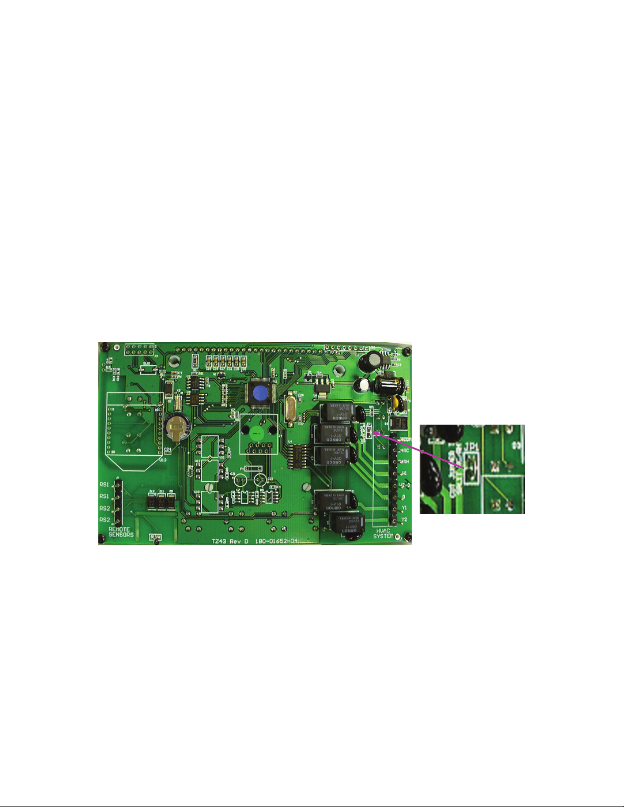
Common or Split Transformer Systems
Most HVAC systems have a common heating and cooling transformer. A jumper wire is connected to tie the RH and RC
inputs together for this configuration. If you have a system with separate heating and cooling transformers, you will need
to separate the RH and RC inputs by cutting the jumper on the PCB.
When wiring split systems, wire the heating systems 24VAC R (red wire) to the thermostat’s RH terminal, and wire the
cooling systems 24VAC R to the thermostat’s RC terminal. Also wire the cooling systems 24VAC Com to the thermostat’s
24VAC Com terminals.
Note: Do not split RC/RH for Heat Pump systems!
33
Page 34

Warranty
Trane Remote Energy Management Thermostat
Limited One (1)-Year Electronics and Mechanical Warranty
U.S.A. and Canada Only
Subject to the terms and conditions of this Limited One (1)-Year Electronics and Mechanical Warranty, Trane warrants that,
if within one (1) year from Original Date of Purchase, the Purchased Product fails due to defect in manufacture, material
or workmanship, Trane will provide a replacement for the Purchased Product or refund the Original Purchase Price, at its
sole option, to the Original Purchaser occupying the premises in which the Purchased Product was originally installed.
This warranty applies to the Original Purchaser only and is non-transferable. The one (1)-year limited warranty period
begins from Original Date of Purchase, confirmed by sales receipt or other dated proof of purchase.
Exclusions: The following costs, expenses and damages are not covered by the terms and conditions of this One(1)-Year
Limited Electronics and Mechanical Warranty: (i) labor and costs including, but not limited to, original initial installation,
removal and reinstallation of Purchased Product; (ii) shipping and freight expenses for any required return of Purchased
Product; (iii) failures, defects, or damages (including, but not limited to, any security failure or loss of data) caused by any
third party product, service, or system connected or used in conjunction with the Purchased Product; and (iv) any other
incidental, consequential, indirect, special and/or punitive damages, whether based on contract, warranty (express or
implied), tort (including, but not limited to, strict liability or negligence), patent infringement, or otherwise, even if advised
of the possibility of such damages. Additionally, this limited warranty does not cover scratches, abrasions, or deterioration
due to the use of paints, solvents or other chemicals.
Further, the terms and conditions of this One (1)-Year Limited Electronics and Mechanical Warranty do not apply to
Purchased Product when: (1) used in common area applications (2) used for purposes for which it was not designed or
intended; (3) subjected to alteration, modification, abuse, misuse, negligence or accident, improper storage, improper
installation or maintenance or operation or unauthorized repair; (4) used in violation of written instructions provided for
Purchased Product; (5) subjected to improper temperature, humidity or other environmental conditions; or (6) damaged as
a result of acts of God.
This One (1)-Year Limited Electronics and Mechanical Warranty is the only express warranty Trane makes on this
product. THE DURATION OF ANY IMPLIED WARRANTIES, INCLUDING THE WARRANTIES OF MERCHANTABILITY
AND FITNESS FOR A PARTICULAR PURPOSE, IS HEREBY LIMITED TO THE ONE-YEAR DURATION OF THIS
WARRANTY. IF THIS PURCHASED PRODUCT IS CONSIDERED A CONSUMER PRODUCT, SOME STATES DO NOT
ALLOW THE EXCLUSION OR LIMITATION OF INCIDENTAL OR CONSEQUENTIAL DAMAGES, SO THIS LIMITATION
MAY NOT APPLY TO YOU. REFER TO YOUR LOCAL LAWS FOR YOUR SPECIFIC RIGHTS UNDER THIS WARRANTY.
Additional items: Trane does not authorize any person to create for it any obligation or liability in connection with the
Purchased Product. Trane’s maximum liability hereunder is limited to the Original Purchase Price of the Purchased
Product. No action arising out of any claimed breach of this warranty by Trane may be brought by the Original Purchaser
more than one (1) year after the cause of action has arisen.
If you have a claim under this warranty, please return the Purchased Product to place of purchase for replacement or
refund of the Original Purchase Price in exchange for the return of the Purchased Product, including sales receipt or other
dated proof of purchase. Contact Schlage Customer Service at 877-288-7707 in U.S.A. and Canada for assistance with
set-up and installation, or questions regarding your warranty claim.
©2009 Schlage Lock Company
thermostat user guide Rev. 05/09-a
 Loading...