

Page 1

Instruction Manual for
Altazimuth Mount
Page 2

PERFACE
The SKYPOD Altazimuth Mount features automatic slewing of celestial objects on the screen of its dedicated hand controller ‘STAR BOOK-S’
and a various convenient menus and functions that will help you in enjoying your observation in the night sky. We hope you will enjoy exploring
celestial wonders anywhere with the SKYPOD.
This manual is prepared in common with all the SKYPOD ser
your model, this depends on the model you purchased.
We thank you very much for your purchase of our product from a series of the
Vixen SKYPOD Altazimuth Mount astronomical telescopes.
ies telescopes. You may occasionally find descriptions in the text not relevant to
Please read this instruction manual carefully before use, and follow them precisely.
Always keep the instruction manual near to your mount or telescope to enable any operational queries to be easily answered.
This instruction manual describes necessary precautions for the safe use of the product by preventing yourself and others from possible
injuries as well as damages to the equipment.
WARNING!
Never look directly at the sun with your naked eyes or through any telescope or its
finder scope or guide scope. Permanent and irreversible eye damage may result.
Never connect the cable of the STAR BOOK-S with other equipment such as a PC. It may cause
a failure, heating, or electrical shock.
CAUTION
Do not try to restrain the movement when the mount in operation, which may lead to injuries to yourself
or equipment damage.
Do not leave the optical tube uncapped in daytime. It may cause a fire from the objective lens or mirror
of the optical tube or finder scope in case of sunlight passing through the telescope.
Do not use the product while moving or walking, where injuries could arise from collision with objects or
stumbling or falling.
Keep tiny caps, desiccant, or vinyl packing materials away from children. It may cause danger from
swallowing or suffocation.
Do not use the product in a wet environment and do not touch with wet hands.
Do not turn the power switches of the SKYPOD and STAR BOOK-S to on under conditions that internal
dew condensation is suspected on them. It may cause failure by leakage of electricity.
HANDLING
Do not leave the product inside a car in bright sunshine, or in hot places. Keep any strong heat radiation
sources away from the product.
When cleaning, do not use the organic solvent such as paint thinners or similar.
Do not expose the product to rain, water drops, dirt or sand.
Avoid touching any lens or mirror surfaces directly with hands. In case a lens or mirror becomes dirty with
fingerprints or general smears, gently wipe it using a commercially available lens cleaner and a lens cleaning
paper, or consult your local Vixen dealer.
Blow off dust on lens using a commercially available blower brush.
For storage, keep the product in dry places, and do not expose to direct sunlight.
Remove the batteries from the battery box while the product is not used for a long time.
This equipment has been tested and found to comply with the limits for a Class B digital device, pursuant
of Part 15 of the FCC Rules.
2
Page 3

CONTENTS
PREFACE----------------------2 INITIAL SETTING--------------17
Setting Up the STAR BOOK-S
I.
WARNING,CAUTION,HANDLING---2
CONTENTS --------------------3
BEFORE USE------------------4
Checking Contents --------------------4
Principle and Basic Operation of --------4
Altazimuth Mounts---------------------4
Parts Descriptions---------------------5
STAR BOOK-S Hand Controller---------6
Specifications-------------------------7
Turning the Power On and Off------17
II.
Setting Language-----------------18
Setting Local Time----------------19
III.
Setting Location ------------------20
IV.
V
Saving the Settings ---------------21
.
BASIC OPERATION------------22
Moving the Telescope -------------22
I.
Viewing Terrestrial Landscape -----23
II.
Changing the Magnification--------26
III.
Why you Need a Finder Scope-----26
IV.
Observing the Moon --------------29
V
.
HOW TO USE ------------------8
Flow of Operation----------------------8
PERPARATION-----------------9
About Batteries for the SKYPOD--------9
Install Batteries in the SKYPOD --------9
Setting up the Telescope
I.
Setting up the Tripod--------------10
II.
Attaching the SKYPOD Mount -----10
Install Batteries into the Battery----11
III.
Pack on the SKYPOD Mount
IV.
Attaching the Counterweight-------12
(Optional)
V.
Preparation for Mounting the Optical
Tube-----------------------------12
Attaching the Optical Tube---------12
VI.
Attaching the Eyepiece Adapter----13
VII.
Attaching the Finder Scope--------13
VIII.
Balancing the Telescope ----------15
IX.
Connecting the STAR BOOK-S Cable
X.
to the SKYPOD-------------------16
XI.
Connecting External Power Supply--16
AUTOMATIC SLEWING---------31
Automatic Slewing ----------------31
I.
Flow of Automatic Slewing---------31
II.
Home Position--------------------31
III.
Align the Telescope ---------------32
IV.
Starting Automatic Slewing --------38
V
.
Choosing a Target from the Object
VI.
Menu ----------------------------40
Completing Observing-------------42
VII.
APPLICATION -----------------44
Chart Setting
I.
LCD Adjustment ------------------45
II.
Backlighting Duration Adjustment---46
III.
About STAR BOOK-S -------------47
IV.
Saving the Settings ---------------47
V
.
Using the STAR BOOK-S as a Stand
VI.
Alone Unit ------------------------47
3
Page 4
BEFORE USE
Checking Contents
The SKYPOD Altazimuth Mount box contains
the parts listed below. Make sure that your
box contains all these parts.
Contents of SKYPOD Altazimuth Mount
SKYPOD Altazimuth Mount
STAR BOOK-S Hand Controller
STAR BOOK-S
Instr
uction Manual (This booklet)
ial Number Stickers
Ser
Note : Batteries are not included.
For parts included in optical tube boxes and other
instruments, please refer to that product manual.
Instruction Manual (This booklet)
SKYPOD Altazimuth Mount
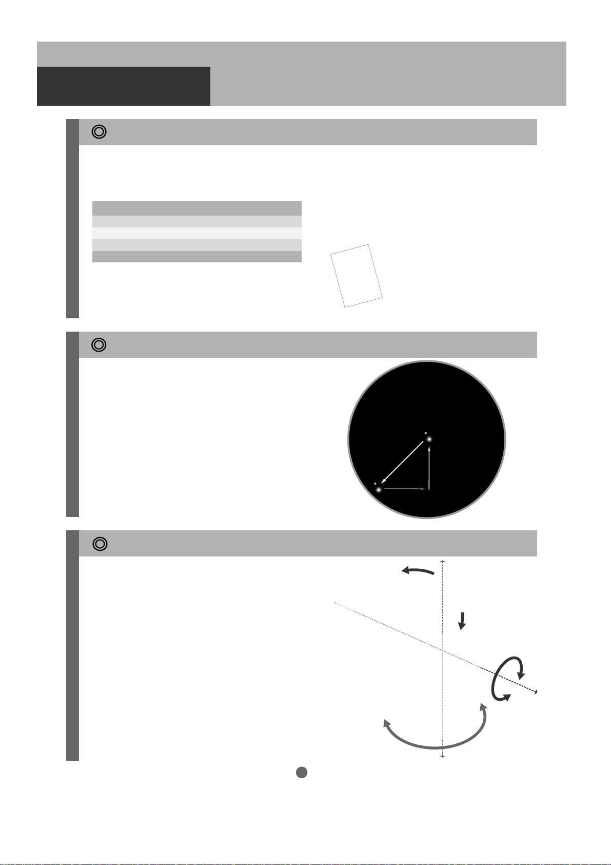
Principle and Basic Operation of Altazimuth Mounts
What is an Altazimuth Mount?
The Altazimuth mount is a telescope platform
with simple vertical and horizontal motion controls
that allow you to move the telescope up and down
and side to side.
Due to Earth’s rotation, the mount must move to
follow a celestial object. Without this movement,
stars and celestial objects move through the field
of view as time passes by. An Altazimuth mount
moves in altitude(
to keep the object you are viewing centered in the
field of view of your telescope.
vertically
)and azimuth(
horizontally
Apparent movement of stars
)
Moves horizontally
(in azimuth motion)
Moves vertically
(in altitude motion)
Basic Operation
The STAR BOOK-S automatic GoTo controller
controls the motion of the SKYPOD. The SKYPOD functions smoothly and accurately when
the weight of each component is properly
balanced. Using the SKYPOD without proper
balancing may cause tracking errors, slippage
of the telescope tube, or interruption of observation. Make sure to balance the telescope.
For a proper balancing procedure, please refer
to page.15
(Balancing may not be necessary depending on
models of the SKYPOD.)
Vertical Rotation Axis
Horizontal Rotation Axis
4
Page 5
BEFORE USE
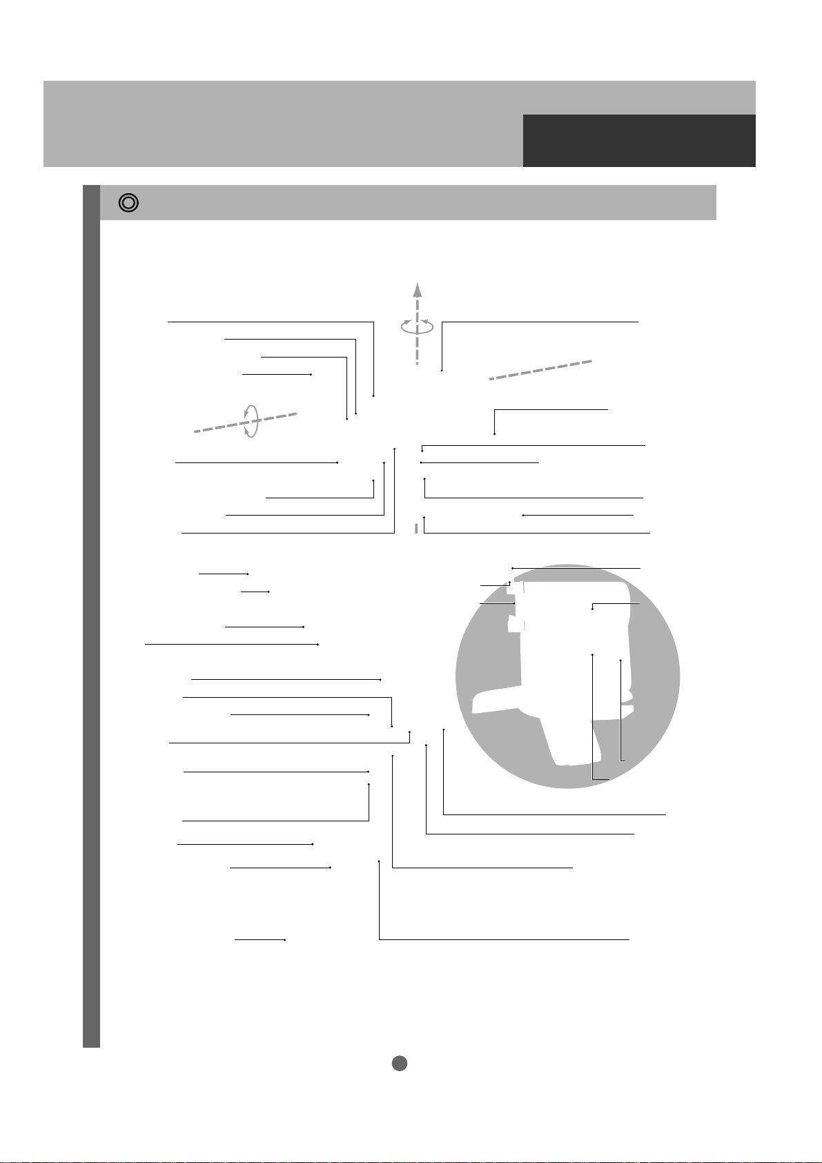
Parts Descriptions : SKYPOD Mount and Tripod
SKYPOD VMC110L and A80Mf telescopes shown here, your telescope may differ.
Horizontal Rotation Axis
Eyepiece
Eyepiece Set Screw
Finder Bracket Lock Screw
VMC110L Optical Tube
Dot Finder
Eyepiece Adapter (31.7mm)
Eyepiece Set Screw
Focus Knob
Objective Hood
Objective lens (Inside)
A80Mf Optical Tube
Tube
Finder Scope
Focus Knob
Half Pillar (Optional)
Safety Screw
Dovetail Mounting Block
STAR BOOK-S
Vertical Rotation Axis
Compartment Cover
Power Switch
External DC 12V Power Terminal
Auxiliary Port
Tabletop Tripod
Fixing Knob
Dovetail-Plate
Lock Screw
STAR BOOK-S
Rack
Drawtube
Tripod Head
Fixing Knob
Tripod Leg
Tripod Leg Spreader
Leg Extension Clamp
Cable Connector
Battery Case Cover
Battery Case
Eyepiece
Diagonal Prism
Azimuth Adjustment Screw
5
(Not used)
Accessory Tray
Page 6
BEFORE USE
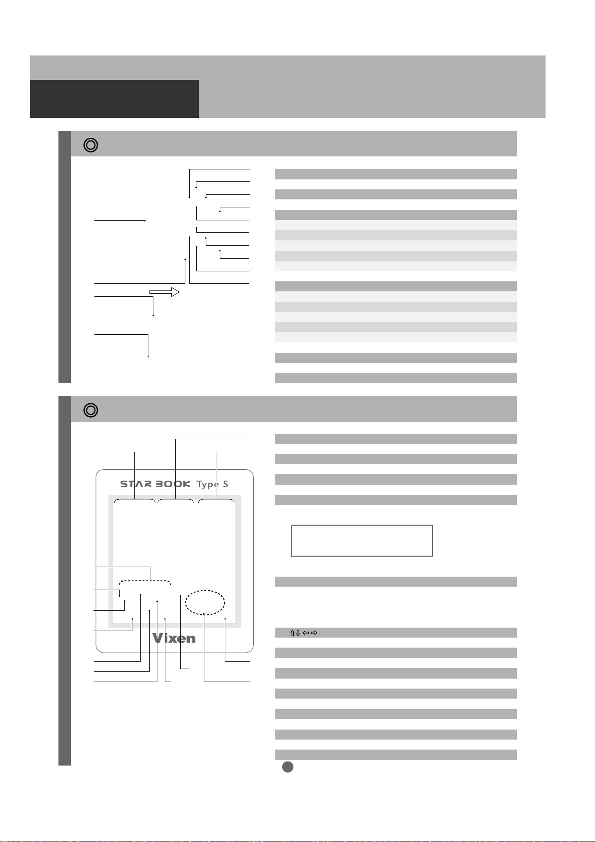
STAR BOOK-S Hand Controller
01
02
13
14
03
01. TN 2.6-inch Monochrome LCD Screen
04
05
02. Power Switch
07
The upper buttons (Right side on-screen soft-key legend): Enter, Cursor Movement, Scroll
06
03. LEFT (Moves the cursor left. <The screen scrolls toward right.>)
09
04. UP (Moves the cursor up. <The screen scrolls down.>)
10
05. RIGHT (Moves the cursor right. <The screen scrolls toward left.>)
06. DOWN (Moves the cursor down. <The screen scrolls up.>
12
07. ENTER (Changing Chart / Scope modes)
11
08
The lower buttons (Left side on-screen soft-key legend): Alignment, Zoom
08. MENU (Accesses various settings on the system menu.)
09. ZOOM+(Zooms in the screen in 8 steps.)
10. ALIGN (Aligns computer with telescope position.)
11. ZOOM-(Zooms out the screen in 8 steps.)
12. DISP (On screen information changes each time pressed.)
Legend on the Screen
01
04
05
11
10
08
09
12
05
13. LAN :
14. MOUNT: Controller Cable Connection Terminal
02
01. Mode Display: SCOPE Mode and CHART Mode
03
02. Date
03. Time
04. Battery Level: Varies according to a level of discharge.
The battery levels are displayed individually for both the
STAR BOOK-S and the SKYPOD Mount.
Note: The SKYPOD battery level indicator may show “Empty” when
the controller cable is not connected securely.
05. Upward Arrow / Downward Arrow
Upward Arrow: A bunch of on-screen soft-keys corresponding to
the upper buttons.
Downward Arrow: A bunch of on-screen soft-keys corresponding
to the lower buttons.
06. : Directional keys and cursor movement
07. Select, Automatic Slewing and changing Chart / Scope mode
07
08. Zoom + : Zoom in the screen.
0613
09. Zoom – : Zoom out the screen.
LAN Connection Terminal (10BASE-T) for communication with a PC
Full Middle Empty
10. MT : Speed of scrolling the screen / zooming visually.
11.
Menu :
12. Align : Set up directions (alignment) for automatic slewing
6
Open the System Menu dialog box to change various settings.
Page 7

13. Disp: On screen information changes each time pressed.
<Soft-key legend> <RA and Dec> <No indication>
SKYPOD Mount Specifications
BEFORE USE
Legend on the Screen
Mount
Altitude worm wheel
Azimuth worm wheel
Coordinates of object
Slo
w
motion controls
wing speed
Sle
A
uxiliary terminal
Batter
ies
W
orking duration with batteries
Exter
nal power supply
Maxim
um loading weight
Dimensions
W
e
ight
Optional Accessor
ies
Altazimuth GOTO Mount
Full circle 70-tooth gear
Full circle 70-tooth gear
Show
n on the STAR BOOK-S in 0.1’ increment
ic, 8-speed in both axes
Electr
Max.
900x (sidereal rate)
D-SUB 9 Pin (una
8 x AA-size alkaline batter
8hrs at 20 degrees C
DC12V EIAJ RC5320A Class4
About 5kg with an optional counterwe
210mmW x 200mmL x 190mmH (without tr
2.8kg (Incl.
Two-section aluminum tripod, Counterweight
(Supplied as standard accessor
vailab
. (68F) ambient temperature
controller and cab
STAR BOOK-S Specifications
Controller
CPU
Display
Au
toguider Port
Controller cable connection terminal
LAN connection terminal
Batteries
Working duration with batteries
Dimensions
W
e
ight
Celestial objects stored in memory
Other functions / Capabilities
STAR BOOK-S
32Bit RISC processor CS89712
TN 2.6-inch monochrome LCD screen (160 x 160 = 25600 pixels)
6-pole 6-wired modular jac
8-pole 8-wired modular jack
10BASE-T
4 x AA-size
8hrs at 20 degrees C
124mmW x 85mmL x 38mmH
165g (without batteri
Total 22,735 objects consisting of:
17,635 fix
4,980 NGC/IC objects brighter than 14th magnitude
Software upgrade via LAN connection
Built-in speak
Oper
alkaline batter
. of ambient temperature
es and cab
ed stars br
ating temperature between 0 deg-C. and 40 deg-C.
ighter than 7-th magnitude, 110 Messier objects,
er
le)
ies
k
ies
ight
le)
ies f
or some models.)
le)
ipod)
, 8 Planets, the Moon and Sun
7
Page 8
HOW TO USE
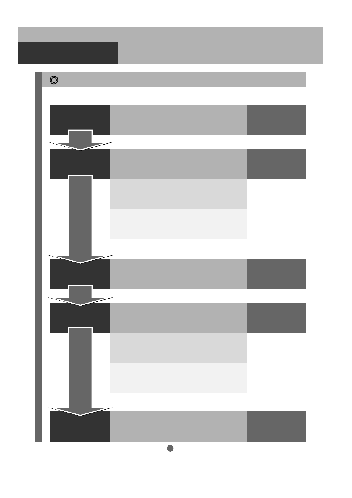
Flow of Operation
Take the following steps to set up the SKYPOD.
PREPARATION
INITIAL SETTING
BASIC OPERATION
Assembling the SKYPOD and tripod.
Setting Language (The first time only.)
Tur n the powers of both the mount and controller to ON,
and then choose your language in the STAR BOOK-S.
Setting Date & Time (The first time only.)
Enter date and your local time.
Setting Longitude & Latitude
Enter longitude and latitude of your observation site.
Read the manual to understand basic operation
of the SKYPOD.
(The first time only.)
Pages 09 to 16
Pages 17 to 21
Pages 22 to 30
AUTOMATIC SLEWING
APPLICATION
Home Position
Slew the telescope to the home position by using the
STAR BOOK-S hand controller.
*The‘Home Position’is the initial set-up position of the
SKYPOD which is required
Alignment
Choose two out of many celestial reference points stored
in the STAR BOOK-S database.
Automatic Slewing
Upon completion of alignment, automatic Go To slewing
and tracking are available.
Finish Operation
8
Pages 31 to 43
Page 44 to 47
Page 9
PREPARATION
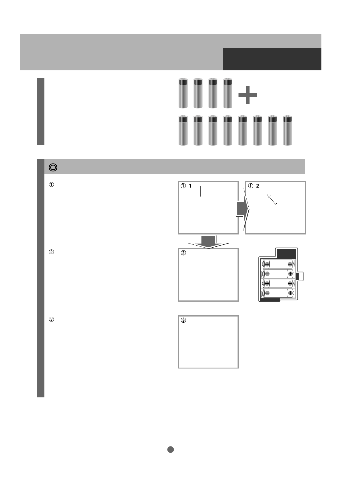
About batteries for the SKYPOD
The STAR BOOK-S controller of the SKYPOD runs
on four (4) AA-size alkaline batteries (not included).
The batteries can last about eight hours at 20 degrees C.
The SKYPOD Mount runs on eight (8) AA-size alkaline
batteries (not included) or optional external power supply.
The batteries can last about eight hours at 20 degrees C.
A total of twelve (12) AA-size alkaline batteries are
needed optionally to run the product.
How to insert the batteries into the STAR BOOK-S
Push the latch of the rear cover down and
open the cover toward you as shown in the
figure.
Insert fresh batteries (4 x AA-size alkaline
batteries). Do not mix up the polarity as it
may cause a failure.
Replace the cover to complete.
Rear Cover
Install batteries in the SKYPOD.
Explanation on how to install the batteries is stated in the “PREPARATION Setting up the
telescope” section for the sake of convenience. (See page 11 of this manual.)
9
Page 10
PREPARATION
Setting up the Tripod
Setting up the telescope
Stand the tripod on even
and sold ground. Adjust
the height of the tripod
as the occasion demands.
To change the height,
loosen the leg extension
clamp of each tripod leg.
Be sure to tighten all the
Leg Extension ClampLeg Extension Clamp
leg extension clamps
securely after adjusting
the height of the tripod.
Take off the tray lock
knob at the center of the
tripod leg spreader to
reveal the tray anchor
bolt.
Tray Anchor BoltTray Anchor Bolt
Attaching the Half Pillar (Optional)
(Proceed to II when you don't need the Half Pillar for
your SKYPOD.)
Use an optional Half Pillar when your telescope optical
tube can hit the tripod leg. Hold the Half Pillar over
the tripod head so that the center shaft is above the
matching hole. Place the Half Pillar on the tripod head
so that the two are flush. Tighten the locking knob
on the underside of the tripod head firmly.
Pull the tripod legs apart
until the tripod leg spreader has been fully extended to let the tripod stand
by itself.
Place the accessory tray
over the tripod leg spreader and position it so the
anchor bolt on the tripod
leg spreader fits the matching hole at the center of
the accessory tray. Then,
attach the accessory tray
with the tray lock knob.
Half Pillar
Half Pillar
Tripod Head
Tripod Head
Accessory Tray
Accessory Tray
(Not used)
(Not used)
Tripod Leg
Tripod Leg
Spreader
Spreader
Tray Lock
Tray Lock
Knob
Knob
Half Pillar
Half Pillar
Locking Knob
Locking Knob
Hold the SKYPOD Mount over the Half Pillar so that the center shaft is above the matching hole. Place the SKYPOD
Mount on the Half Pillar so that the two are flush. Tighten the locking knob on the underside of the tripod head fir mly.
Attaching the SKYPOD Mount
Hold the SKYPOD Mount over the tripod head
so that the center shaft is above the matching
hole. Place the SKYPOD Mount on the tripod
head so that the two are flush. Tighten the
locking knob on the underside of the tripod
head firmly.
SKYPOD
SKYPOD
Mount
Mount
Tripod Head
Tripod Head
10
Locking KnobLocking Knob
Page 11
Setting up the telescope
PERPARATION
Attaching to the Tabletop Tripod
Hold the SKYPOD Mount over
the tabletop tripod head so that
SKYPOD
the center shaft is above the
SKYPOD
Mount
Mount
matching hole.
Place the SKYPOD Mount on
Tabletop
the tabletop tripod head so that
Tabletop
Tripod
Tripod
the two are flush. Tighten the
knob on the underside of the
tripod head firmly.
Locking KnobLocking Knob
Install batteries into the battery pack on the SKYPOD Mount.
Open the front cover to access the inner blue
battery case as shown in the figure. Open the
battery case by sliding off its top cover.
Take out the battery pack and inser t the fresh
batteries into it. Do not mix up the polarity as
this may cause a failure.
Put the battery pack back into the blue battery
case. Turn the projection on the battery pack
so that it fits into the recess of the battery case
as shown in the figure below. Close the cover
as it was
Compartment
Compartment
Cover
Cover
Battery Pack
Battery Pack
Slide Cover
Slide Cover
Slide Cover
Slide Cover
Batteries
Batteries
(AA x 8)
(AA x 8)
Projection on the
Projection on the
Battery Pack
Battery Pack
11
Compartment
Compartment
Cover
Cover
Page 12

PREPARATION
Setting up the telescope
Attaching the Counterweight (Optional)
(Proceed to V when you don't need the Counterweight for your SKYPOD.)
Use an optional counterweight with the SKYPOD when you install a telescope optical tube weighing
over 2.5 kg (5.5lbs.). Remove the blue weight cap by unscrewing it and screw the counterweight
onto the end of counterweight shaft inside.
Replace the counterweight
cap after making sure that
the counterweight is tightly
secured inside.
Counterweight ShaftCounterweight Shaft
Weight CapWeight Cap Weight CapWeight Cap
CounterweighCounterweigh
WARNING!
Handle the counterweight with care as it is heavy.
Preparation for Mounting the Optical Tube
Loosen both the dovetail-plate lock screw and
safety screw until the tips of these screws no
longer extended into the inner part of the dovetail
block.
Dovetail-Plate
Dovetail-Plate
Lock Screw
Lock Screw
Safety Screw
Safety Screw
Attaching the Optical Tube
Slide the dovetail mounted scope into the dovetail mounting block of the SKYPOD, tighten the dovetailplate lock screw (centered on the notch) onto the dovetail tube plate until snug.
Dovetail-Plate
Dovetail-Plate
Lock Screw
Next, tighten the small
chrome safety screw onto
the dovetail mounting block
until snug.
Lock Screw
Dovetail Tube Plate Safety Screw Gap
Dovetail Tube Plate Safety Screw Gap
Caution Caution
Optical tube assemblies are seriously damaged if
dropped. Tighten the dovetail-plate lock screw
securely. The safety screw should also be screwed
in completely.
12
Make sure that the dovetail tube plate is flat against
the dovetail mounting block. Tightening the dovetailplate lock screw with a gap between these parts may
result in the telescope unexpectedly falling off.
Page 13
PREPARATION
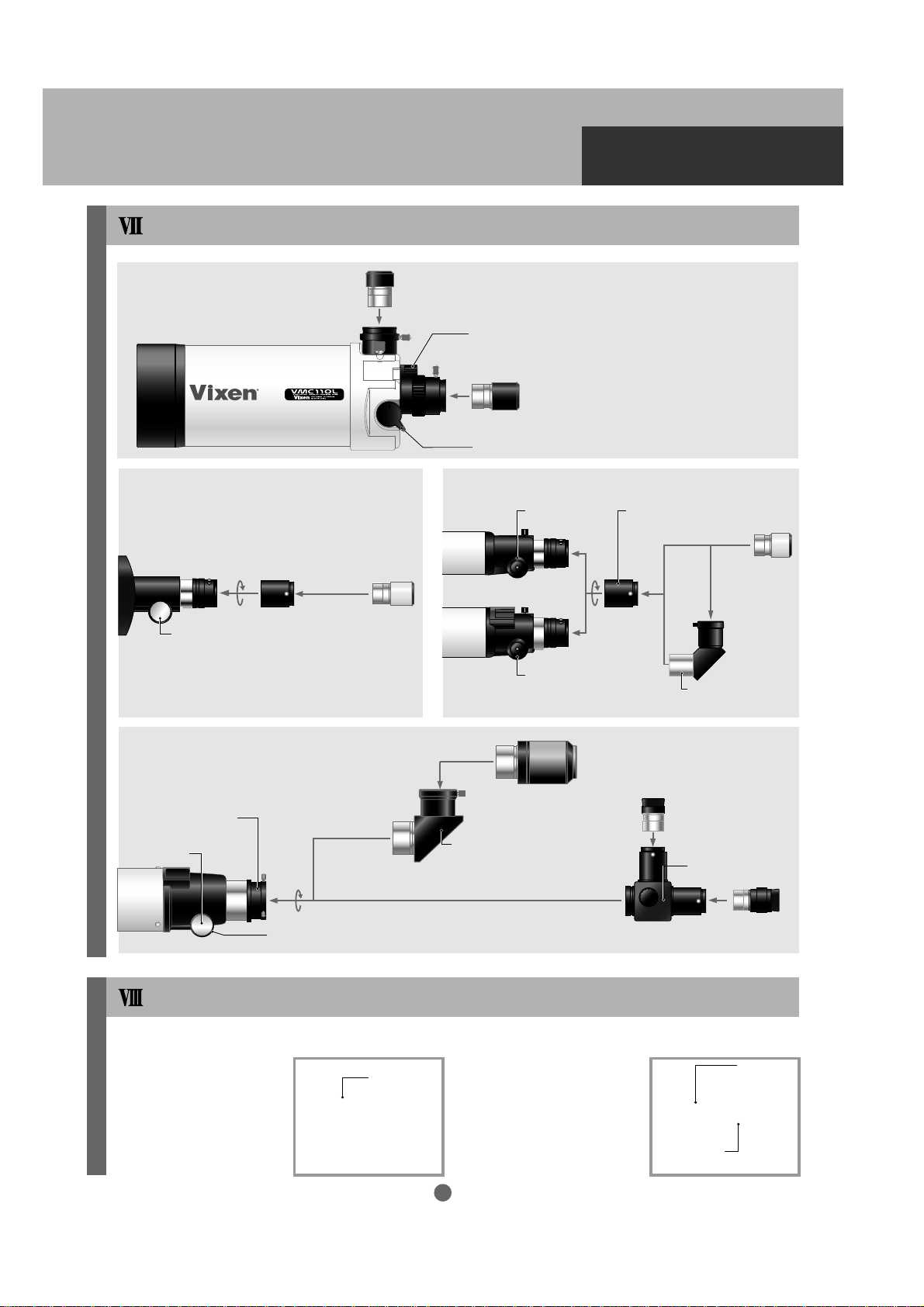
ATTACHING THE EYEPIECE ADAPTER
VMC110L Focuser Visual
Configuration
Right-angled Viewing
Eyepiece Adapter
R130Sf
Focus Knob
(42mm to 31.7mm / 11/4”)
31.7mm / 11/4”(Supplied)
Eyepiece
ED80Sf Focuser Visual Configuration
Focus Knob
Straight-through Viewing
Flip Mirror Lever (Changes the light path.)
A70Lf, A80Mf Focusers Visual ConfigurationR130Sf Focuser Visual Configuration
A70Lf
A80Mf
Eyepiece 31.7mm / 11/4”(Supplied)
Focus Knob Eyepiece Adapter
Focus Knob
Eyepiece 50.8mm/2” (Optional)
(42mm to 31.7mm / 11/4”)
Erect-Image Diagonal
Eyepiece
31.7mm / 11/4”
(Supplied)
31.7mm / 11/4”
(Supplied
50.8mm Adapter/2”
(Supplied)
Focus Knob
ED80Sf
Tension Adjustment Screw (underneath)
ATTACHING THE FINDER SCOPE
Diagonal Mirror
50.8mm/2” (Optional)
on the telescope you purchased.
Attaching the Finder Scope (Dot Finder)
Loosen the chrome finder
bracket lock screw on the
telescope.
Finder Bracket
Finder Bracket
Lock Screw
Lock Screw
Attach the finder scope as
shown in the figure. Tighten
the finder bracket lock
screw securely.
13
Flip Mirror (Supplied)
Eyepiece
31.7mm / 11/4”
(Supplied)
The included finder scope is different depending
(
Dot Finder
Dot Finder
Finder Bracket
Finder Bracket
Lock Screw
Lock Screw
)
Page 14
PREPARATION
Attaching the Finder Scope (A80Mf or R130Sf)
Back out the adjustment screws on the
finder bracket to allow
passage of the finder
scope. (Make sure the
adjustment screws do
not fall off the bracket.)
Pull up the fixed stud
on the bracket ring so
that the finder tube can
slide into the bracket
ring from its eyepiece
end. Release the fixed
stud into the wide groove on the finder tube.
Loosen the finder bracket lock screw on the
telescope.
Finder Bracket
Finder Bracket
Lock Screw
Lock Screw
Adjustment
Adjustment
Screw
Screw
Finder Bracket
Finder Bracket
Slide the rubber O-ring onto the eyepiece end
of the finder. There are two grooves on the
finder tube. Position the O-ring on the narrow
groove at the middle of the finder scope.
Fonder Scope
O-ringGroove
Tighten the two adjustment screws so that the
Adjustment
Screw
finder scope is aligned
as shown in the figure.
Attach the finder bracket
as shown in the figure.
Finder Bracket
Finder Bracket
Lock Screw
Lock Screw
Tighten the finder bracket lock screw securely.
Attaching the Finder Scope (A70Lf)
Remove the two finder
bracket attaching screws
from the telescope.
Finder Bracket
Finder Bracket
Attaching
Attaching
Screws
Screws
14
Attach the bracket on
the finder scope as
shown in the figure.
Tighten the finder bracket attaching screws
securely.
Finder Bracket
Finder Bracket
Attaching
Attaching
Screws
Screws
Page 15
Attaching the Finder Scope (ED80Sf)
Proceed to step 5 if the finder scope is already installed in its bracket.
PREPARATION
Back out the adjustment
screws on the finder
bracket to allow passage
of the finder scope.
(Make sure the adjust ment screws do not
fall off the bracket.)
Pull up the fixed stud
on the bracket ring so
that the finder tube can
slide into the bracket
ring from its eyepiece
end. Release the fixed
stud into the wide groove on the finder tube.
Loosen the finder bracket lock screw on the
telescope.
Adjustment
Adjustment
Screws
Screws
Finder Bracket
Finder Bracket
Finder Bracket
Finder Bracket
Lock Screw
Lock Screw
Slide the rubber O-ring onto the eyepiece end
of the finder. There are two grooves on the finder
tube. Position the O-ring on the narrow groove
at the middle of the finder scope.
Finder Scope
Tighten the two adjustment screws so that the
Groove
O-ringGroove
Adjustment
Adjustment
Screws
Screws
finder scope is aligned
as shown in the figure.
Attach the finder bracket as shown in the
figure. Tighten the finder bracket lock screw
securely.
Finder Bracket
Finder Bracket
Lock Screw
Lock Screw
BALANCING THE TELESCOPE
(Balancing in altitude motion)
Be sure to attach the finder scope, eyepiece, and any other accessories before proceeding.
Balancing an optical tube with tube rings and
Optical Tube with Tube Rings
dovetail tube plate.
(i.e. A70Lf, A80Mf, R130Sf and ED80Sf telescopes)
Loosen the tube ring lock knobs so the optical tube
can slide. Hold the optical tube in the horizontal
position with the dovetail tube plate up and slide the
tube until it's balanced under the center of the plate.
Tube Ring Lock KnobTube Ring Lock Knob
Balancing the VMC110L optical tube
Find the rough center of
balance by holding the
dovetail slide bar of the
VMC110L as shown.
Attach it to the SKYPOD
with this point centered
in the dovetail mount.
VMC110L Optical Tube
Dovetail Slide BarDovetail Slide Bar
15
Warning!
Take great care in holding a telescope this way
as there is a much greater risk of dropping it.
Normally you should hold the tube from underneath.
Page 16

PREPARATION
CONNECTING THE STAR BOOK-S CABLE TO THE SKYPOD
Open the compartment cover on the SKYPOD.
The hand controller cable is wound around the
blue battery case. Unwind it to take out the
modular plug on one end of the cable. Insert
the modular plug into the female jack on the
STAR BOOK-S as shown until it clicks.
Warning!
Never connect the hand controller cable
to other instruments such as a PC. It
may cause a power failure, overheating
or electric shock.
Compartment Cover
Compartment Cover
STAR BOOK Type S
STAR BOOK Type S
Modular Plug
Modular Plug
Hand Controller
Hand Controller
Cable
Cable
Female Jack
Female Jack
CONNECTING EXTERNAL POWER SUPPLY
When using an external DC 12V power supply
or an optional AC Adapter 12V 3A, be sure to
connect the power cable to the SKYPOD mount
before turning on the power switch.
External power terminal
DC12V EIAJ RC5320A Class4
16
Power Cable Power Cable
Power Cable Power Cable
Page 17

TURNING THE POWER ON AND OFF
There are two power switches; one on the
SKYPOD Mount and anther on the STAR
BOOK-S hand controller. The power is supplied
to both components independently so be sure
to turn on both power switches.
Caution
Always turn on the STAR BOOK-S first, then
turn on the SKYPOD Mount in succession.
Reversing this order may make it inoperative.
Confirm that the Vixen logo is displayed on
screen for a few seconds when you turn on
the power of the STAR BOOK-S.
If the screen is hard to read, please refer to
Hint 1 (P18).
The picture on the right will appear on screen
after the Vixen logo when the STAR BOOK-S
power is switched on. Move the cursor with the
keys onto the item you want to
choose and press the
Select
key. Read page
18 also to refer to setting Language.
Power Switch
Power Switch
INITIAL SETTING
Power Switch
Power Switch
On-screen soft keys
The keys on the
right correspond
to the upper
buttons
and those
on the left
espond to the
lower buttons.
How to turn off the power in the above
initial setting screen.
(See page 42 when you discontinue SKYPOD
operation at end of the observation.)
To turn off the power, choose Power Off with
the keys and press the
to enter.
Next the confirmation screen is displayed.
Move the cursor to OK with the
keys and press the
Select
key to enter.
Turn off the power switch on the SKYPOD
Mount.
Caution
Remember to turn the power switch on the
SKYPOD to off as well as the power on the
STAR BOOK-S. Otherwise, the batteries will
be depleted. Turning one component off will
not turn off the other.
Select
key
Power Switch
Power Switch
17
Page 18

INITIAL SETTING
Setting Language
The STAR BOOK-S can be operated with your choice of language with Japanese, English, German,
French, Italian, and Spanish to choose from. Japanese is the default language setting.
Choose /Language with the
keys and press the
Next the screen below is displayed. Choose
your language with the keys and
press the
Select
Select
key to enter.
key to enter.
This will bring you back to the initial screen.
Hint 1
Adjusting the LCD screen
In the initial setting, contrast of the LCD screen can be adjusted with the keys Cont.+ or Cont.-
shown at the lower left of the screen. Adjust it with the corresponding keys according to conditions
of use.
Be sure to save the contrast setting for use
under the same conditions next time.
The contrast of the screen may change with
ambient temperature.
18
Page 19

INITIAL SETTING
Setting Local Time
Enter the date and local time of your observing site by using the upper five buttons on the STAR BOOK-S.
This task is required only once the first time you use the STAR BOOK-S. However, you will need to reset
the date and time if you travel from your regular observing site to a different time zone, or if you reset your
clocks for Daylight Saving time. The STAR BOOK-S keeps the stored memor y while you replace the
batteries. It is not necessary to enter the date and time again if you put in new batteries within an hour.
A deviation may arise between the internal clock of the STAR BOOK-S and your time, but a few minutes’
difference does not affect the slewing performance of the unit.
Choose
keys and press the
To change the date and time, move the cursor
with the keys to the item where
corrections are needed. Then change the
numbers with the keys.
To finish the setting, move the cursor with the
keys to OK and press the
key to enter.
Local Time Setting
with the
Select
key to enter.
Select
19
Page 20

INITIAL SETTING
Setting Location
Enter the longitude, latitude and time zone of
your observing site. Once the settings for your
location are entered and saved, you don’t need
to change them unless you travel more than 15
miles to a different observing location. The
longitude and latitude of your observing site can
be checked on a map or with a GPS device. The
initial location is set at Tokyo.
Choose Location with the keys
and press the
To change the longitude and latitude settings
for your observing site, move the cursor with the
keys to the item where corrections
are needed. Then change the numbers with the
keys.
Select
key to enter.
About Time Zones
The time zones are based on longitude bands 15 degrees wide, starting at Greenwich, England. Set the time
difference in hours between your local time and Greenwich Mean Time (GMT). Its sign is plus if local time is
ahead of GMT (east of Greenwich) and minus if local time is behind GMT (west of Greenwich). For example,
the time zone for Los Angeles (on Pacific Standard Time) is -8 hours.
Please note that the entered time zone setting is not converted to Daylight Saving time automatically. When you
reset your clocks for Daylight time, add one hour to the value in the Time Zone setting, as well as in the Local
Time Setting. Adding to a negative value will lower the number. For example, when changing to Daylight time
in Los Angeles, change the setting from -8 to -7.
To finish the setting, move the cursor to OK
with the keys and press the
key to enter. The screen will go to the reboot
screen. If the location settings remain the
same as last time, it will go back to the initial
screen.
The STAR BOOK-S will ask to reboot. Press
the
Select
key to choose OK .
Select
To continue, press the power button to switch
on again.
20
Page 21

INITIAL SETTING
Saving the Settings
Save your time, language and contrast settings for the next use. Failure to do so will result in having
to re-enter these settings every time you turn on the power.
Once you save the settings, they will be stored in the memory of the STAR BOOK-S and you can simply
choose OK to advance the screen the next time you use it.
Choose Save Setting with the
keys and press the
Next the confirmation screen is displayed. Move
the cursor to OK with the keys
and press the
Select
Select
key to enter.
key to enter.
Now all the entered data are saved and the
screen goes back to the initial setting screen.
21
Page 22

BASIC OPERATION
MOVING THE TELESCOPE
A VMC110L telescope is used here as an example. Your telescope tube may differ. Please read the
instruction manual that is appropriate to your model.
In the initial screen, move the cursor to OK
with the keys and press the
key to enter.
The screen displays a warning on solar
observation.
Select
After reading the text, choose Confirm with
the keys and press the
key to enter.
The warning continues on the screen when
Not Confirm is chosen.
The screen advances to home position setting
as soon as you choose the Confirm key.
However, please disregard it here and press
OK with the
in the daytime.
Select
key to continue operation
Select
22
Page 23

Press the keys to
see in what direction the telescope tube moves.
The keys move the telescope left
and right, and the keys move it up
and down. (The telescope may not move below
the horizon.)
Note: The SKYPOD star ts driving at sidereal
rate (the speed of Earth’s rotation) as soon
as the OK key is pressed in the home position
setting screen.
Hand Controller
BASIC OPERATION
Vertical Rotational Axis
Horizontal Rotational Axis
VIEWING TERRESTRIAL LANDSCAPE
Let’s have a look through the telescope. The best way to become familiar with a telescope is to learn
how to use it in the daytime. It is difficult for the novice telescope user to start observing under a
dark sky at night. Start out with terrestrial viewing.
WARNING!
Place the telescope in an open area where you can view in excess of 200m/660ft away. Make
sure that there are no obstacles around the telescope. Using the telescope outdoors is most
recommended. Refer to Hint 2 .
When viewing through a window the image is often fuzzy or ‘doubled’. When there is a temperature
difference between indoors and outdoors the image may not be clear, as it may be affected by
turbulence from air flowing out/in through an open window. (Although a drifting image may also
be seen outdoors, it is considered very stable when compared with indoors.)
Never look directly at the sun with your naked eye or through any telescope or its
finder scope or guide scope. Permanent and irreversible eye damage may result.
Hint 2
23
Page 24

BASIC OPERATION
Take off the objective lens
cap and eyepiece cap.
The location of the cap
on your telescope may
differ from model to model.
Do you know where on the
telescope to look through?
Do you know where the
front of the telescope is?
Refer to the figures shown
on the right.
Objective Lens Cap
Objective Lens Cap
(Catadioptrics)
(Catadioptrics)
Objective Lens Cap
Objective Lens Cap
(Refractors)
(Refractors)
Eyepiece Cap
Eyepiece Cap
(Catadioptrics)
(Catadioptrics)
Eyepiece Cap
Eyepiece Cap
(Refractors)
(Refractors)
Refractor Telescope Catadioptric Telescope
EyepieceEyepiece
(VMC110L)
(VMC110L)
Objective Lens Cap
Objective Lens Cap
(Reflectors)
(Reflectors)
Eyepiece Cap
Eyepiece Cap
(Reflectors)
(Reflectors)
Reflector TelescopeRefractor Telescope Catadioptric Telescope
Reflector Telescope
EyepieceEyepiece
Astronomical telescopes need eyepieces (ocular lenses) to view images. Confirm where on the
telescope you insert the eyepiece. This may differ from model to model.
Insert a long focal length eyepiece (large number in millimeters, low power) into the eyepiece
holder and secure it with the setscrew. Refer to Hint 6 .
When a flip mirror is provided with the telescope, the eyepiece can be attached on either side: straight
-thru or right-angled. Make sure that the light rays passing through the telescope enter your eyepiece
by turning the mirror shift knob.
Setscrew
Setscrew
Setscrew
Setscrew
Mirror Shift
Mirror Shift
Knob
Knob
24
Page 25

Press the keys (the
upper four buttons on the STAR BOOK-S) to
point the telescope’s front end toward the target
object you choose. (Targets should be in excess
of 200m/660ft away: a building, antenna, tower,
electric pole, etc.) Refer to Hint 4 and Hint 5 .
BASIC OPERATION
Hint 3
When you use the telescope for terrestrial
viewing, leveling the telescope tube by pressing
the keys may make it easier to
find your target object.
Look into the eyepiece.
Refractor Telescope Catadioptric Telescope
Refractor Telescope Catadioptric Telescope
Refractor Telescope Catadioptric Telescope
The image will likely be
out of focus at first. Tur n
the focus knob slowly
clockwise or counterclockwise to find a point
where the image in the
Focus Knob
Focus Knob
Focus Knob
field of view of the eyepiece becomes sharpest.
How will the image appear in the eyepiece?
The image orientation of the target object differs
depending on what type of telescope and visual
accessories are used. The image may be
inverted or tilted but this does not mean the
telescope is out of order. There is no up or
down in space so image orientation is not so
important. Refer to Hint 4 & Hint 5 .
Reflector Telescope
Reflector Telescope
(VMC110L)
(VMC110L)
(VMC110L)
Focus Knob
Focus Knob
Focus Knob
Reflector Telescope
Hint 4
Views produced by reflectors
Inverted view
Views produced by refractors
Inverted view Erect view with Amici prism
Tilted inverted view,
depending on a rotation
of the optical tube.
(roof prism)
Focus Knob
Focus Knob
Focus Knob
25
Page 26

BASIC OPERATION
Tr y the following when the telescope does not produce any image.
* The telescope will not focus at short distances.
It requires a distance of at least 200 meters to
focus an object. Point the telescope as far into
the distance as possible.
* Your target object may be out of the field of
view of the telescope. Aim the telescope
again more carefully.
* If the field of view of the eyepiece is white
(light grey), the telescope may be pointing
at the sky. Level the telescope and aim it at
the object again.
Hint 5
Mirror reversed view with a flip mirror (Right-angled)
Inverted view with a flip mirror (Straight-thru)
* If the field of view of the eyepiece is pitch-dark
in the daytime, it is possible that the mirror shift
knob is not in the correct position to pass the
light rays to your eyepiece (if you are using a
flip mirror or your telescope comes equipped
with an internal flip mirror). Turn the flip mirror
Astronomical telescopes produce upside-down
images. The telescope’s image is inverted when
viewing straight-thru and mirror reversed with
right-angled viewing (with a star diagonal or a flip
mirror). The non-erect orientation of a telescope’s
image may be difficult to get used to.
knob in another direction to switch the light path.
CHANGING THE MAGNIFICATION
(An optional high power eyepiece is needed)
Loosen the eyepiece setscrew and try changing to an eyepiece with a higher
power (smaller number) that is available optionally. Make sure that you
tighten the eyepiece setscrew after changing eyepieces.
Bring the object into focus again. The higher the magnification, the smaller
the range of focus. Tur n the focusing knob more slowly.
The higher the magnification, the larger the object appears. However, the
image is dimmer at higher power than at low power.
Field of view at low power
A Smaller image but you get a wider
(magnification)
field of view and brighter,
sharper image.
When using an eyepiece with short focal length
(small number in millimeters, high power), the
image will be dim and the range of sharp focus
will be small. The image will be harder to see so
begin with an eyepiece with long focal length.
Dividing the focal length of the telescope by
the focal length of the eyepiece gives the magnification.
Hint 6
Setscrew
Setscrew
Eyepiece
Eyepiece
Field of view at high
power (magnification)
A larger image but you get a narrower
field of view and darker, fainter image.
Example: Calculating the eyepiece magnification using a
telescope with 800mm focal length.
Eyepiece Focal length of telescope Focal length of eyepiece Magnification (power)
PL20mm 800mm 20mm x 40
PL 6mm 800mm 6mm x133
26
Page 27

BASIC OPERATION
Ⅳ WHY YOU NEED A FINDER SCOPE
For the novice telescope user it is difficult to locate a selected object in the field of view at high
magnification. Using a finder scope will make this easier.
Be sure to align the finder scope with the telescope before you start observing.
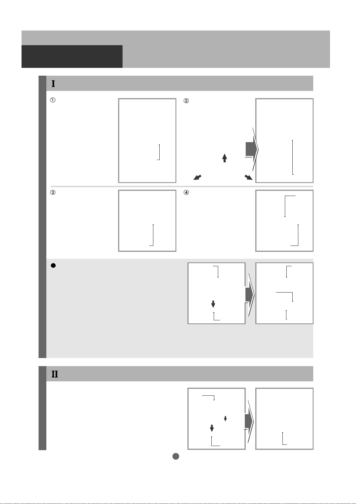
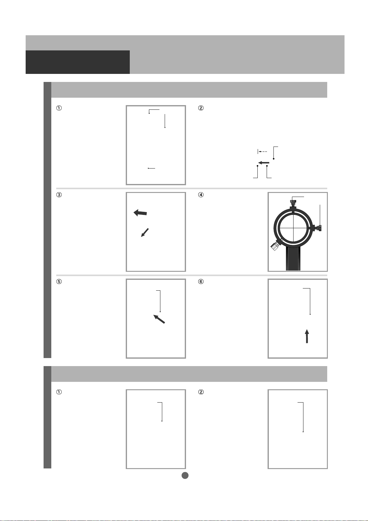
1. Aligning the Finder scope (A80Mf, R130Sf and ED80Sf)
Choose a conspicuous target in the distance
and place the target in the center of the field
of view of the telescope in accordance with
procedures I to III in Basic Operation.
In the illustration, a distant tower is brought
into the center of the field of view of the
telescope.
Next, look through the finder scope. You
should probably find the same target somewhere within the finder’s field of view.
In the illustration, the tower is seen in the
upper right of the finder’s field of view. The
finder scope has crosshairs.
Top
Top
Place the tower in the center
Place the tower in the center
of the telescope’s field of view.
of the telescope’s field of view.
Field of view of
the finder scope
Field of view of the finder scope
Field of view of the finder scope
Adjustment Screw B
Adjustment
Screw A
Align the optical axis (field of view) of the
finder scope with the optical axis (field of view)
of the telescope. Adjust the finder scope by
loosening or tightening the adjustment screws
A and B until the target is in the same position,
in the center of the crosshairs.
Example: The top of the tower can be moved toward the center of the
In the illustration, the top of the tower is
in the center of the crosshairs.
Example: The top of the tower can be moved toward the center of the
crosshairs by looseningthe adjustment screw A and tightening the
crosshairs by looseningthe adjustment screw A and tightening the
adjustment screw C.
adjustment screw C.
Each of the finder scopes is pre-adjusted to focus at infinity before shipment from the factory but
individual eyesight varies. As a result it may not be focused at infinity for you. The finder scopes for
the A80Mf, R130Sf and ED80Sf have a focuser r ing that allows you to make adjustments if necessary.
Standing behind the telescope, loosen the lock ring on the finder
Focuser Ring
scope by turning it counter-clockwise allowing the objective barrel
(front end) to rotate freely.
Focuser Ring
Lock Ring
Lock Ring
While looking through the finder scope as far into the distance as
possible, rotate the objective barrel to find best focus.
When the finder scope is in focus, tighten the lock ring to secure
the objective barrel.
27
Page 28

BASIC OPERATION
2. Aligning the Finder scope (A70Lf)
Choose a conspicuous target in the distance
and place the target in the center of the field
of view of the telescope in accordance with
procedures I to III in Basic Operation.
In the illustration, a distant tower is brought
into the center of the field of view of the
telescope.
Top
Top
Place the tower in the center
Next, look through the finder scope. You
should probably find the same target some-
Place the tower in the center
of the telescope’s field of view.
of the telescope’s field of view.
where within the finder’s field of view.
In the illustration, the tower is seen in the
upper right of the finder’s field of view. The
Adjustment Screw B
finder scope has crosshairs.
Align the optical axis (field of view) of the
finder scope with the optical axis (field of
Field of view of
the finder scope
view) of the telescope. Adjust the finder
scope by loosening or tightening two of three
adjustment screws at a time in turn until the
Adjustment Screw C
target is in the same position, in the center
of the crosshairs.
In the illustration, the top of the tower is in
the center of the crosshairs.
Example: The top of the tower can be moved toward the center of the
Example: The top of the tower can be moved toward the center of the
crosshairs by loosening the adjustment screws A, B and tightening
crosshairs by loosening the adjustment screws A, B and tightening
the adjustment screw C.
the adjustment screw C.
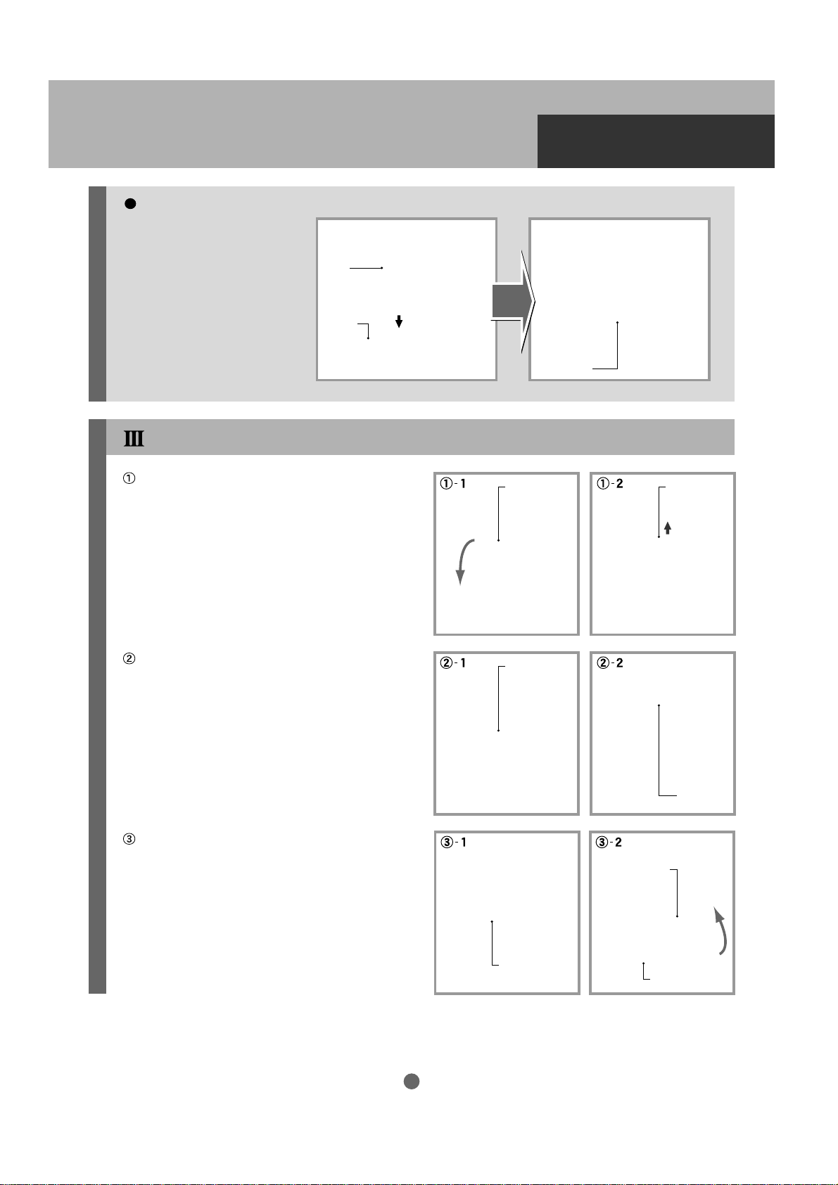
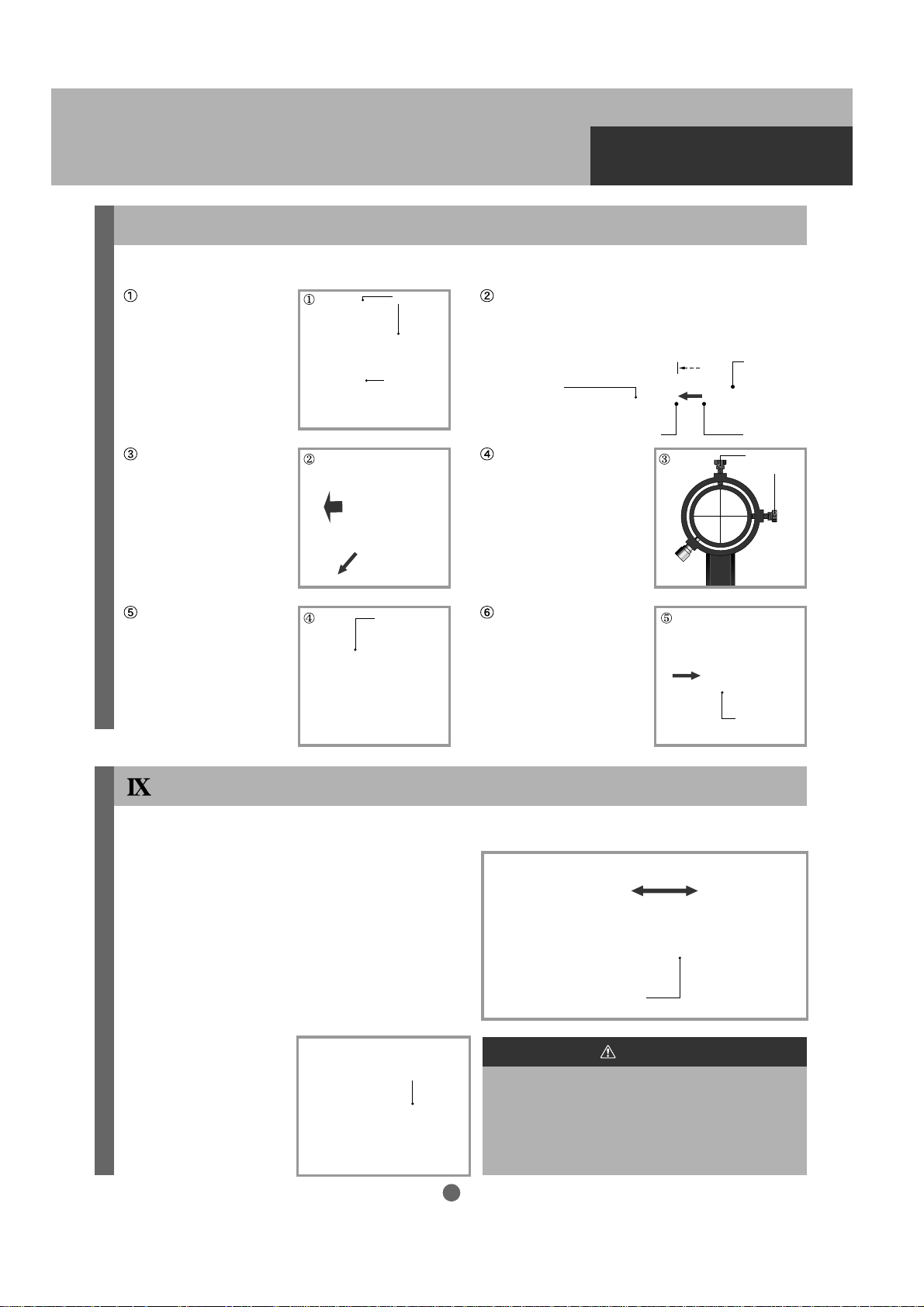
3. Aligning the Finder scope (VMC110L)
Choose a conspicuous target in the distance
and place the target in the center of the field
of view of the telescope in accordance with
procedures I to III in Basic Operation.
In the illustration, a distant tower is brought
into the center of the field of view of the tele scope.
Tur n on the dot finder by turning the brightness adjusting dial. There are graduations
on the dial from 0 to 11. Set the dial at 11.
The intensity of the brightness can be varied
from 1 (faint) to 11 (bright).
You will see a red dot in the center of the field
of view of the dot finder when you look along
the white guideline as shown in the Figure.
Align the optical axis (field of view) of the dot
finder with the optical axis (field of view) of the
telescope. Loosen the alignment clamp on
the dot finder and move the upper portion of
the dot finder by holding its front end until the
red dot is in the same position as the target in
the telescope. Then, tighten the alignment
clamp.
Target
Target
Top
Top
Telescope’s field of view
Telescope’s field of view
Red Dot
Red Dot
White
White
Guideline
Guideline
Target
Target
White
White
Guideline
Guideline
Field of view of
Field of view of
the dot finder
the dot finder
Field of view of the finder scope
Field of view of the finder scope
Adjustment
Screw A
Brightness
Brightness
Adjusting Dial
Adjusting Dial
Graduation
Graduation
Alignment
Alignment
Clamp
Clamp
Target
Target
Set the brightness adjusting dial to 0 to turn
off after using the dot finder.
28
Page 29

OBSERVING CELESTIAL
OBJECTS
Look through the dot finder in a position where a red dot appears in the center.
Hint 7
With the finder scope aligned and the eyepiece attached, you are ready to use the telescope for
celestial observing. Let’s begin by observing a bright and easy-to-find object, the Moon, and then
proceed to finding planets and fainter celestial objects easily visible at moderate power.
The dot finder works as long as the red dot is somewhere in the field of view. However if it is not centered,
the dot may be harder to see clearly and your alignment may not be as accurate. If you have trouble locating
the red dot, look along the guideline (white line) on the dot finder.
OBSERVING THE MOON
Bright and easy-to-find
objects
Moon
Jupiter
Example: What you can expect to see when viewing at a different magnification
Saturn
Moon
Venus
Dim and blurred
celestial objects
Mars
Nebulae and
Star Clusters
Magnification at 50X Magnification at 100X
Aim the telescope at the Moon using the
upper four buttons on the STAR BOOK-S
corresponding to the direction keys on the
right side of the screen to bring the Moon
into the center of the field of view of the
finder scope. (Using the dot finder, center
the red dot on the Moon.)
Jupiter Jupiter
Saturn
Mars
Finder scope’s filed of view Finder scope’s filed of view
SaturnVenus Venus
Mars
Use a low power eyepiece
(large number in mm)
in the telescope and focus on the Moon.
Focus KnobFocus Knob
Telescope’s filed of view
29
Page 30

OBSERVING CELESTIAL
OBJECTS
Tr y using different eyepieces to change the
magnification depending on what type of
lunar features you wish to view.
The Moon (as well as stars and other celestial
objects) will move out of the field of view while
looking through the telescope. This is due
to the Earth’s rotation. The higher the
magnification, the faster the movement.
Re-center the Moon in the field of view by
using the direction keys.
Apply the above same procedure when
pointing the telescope at the planets, such
as Jupiter and Saturn or nebulae and star
clusters.
To learn about positions of these celestial
objects (when and where they can be found),
please refer to commercially available
astronomy magazines.
Eyepiece
Setscrew
Eyepiece
Telescope’s field of view at high power
Drift out of the file of view
Hint 8
The full moon is not suitable for observing
lunar creators in detail because of the lack
of shadows and the overwhelming brightness.
Full moon or nearly full moon
Half moon Straight-thru viewing Right-angled viewing
Hint 9
When you view celestial objects around the
zenith (straight up in the sky), it is much
comfortable to use a right angled diagonal
or a flip mirror as shown in the figure to
look through the eyepiece. But the images
are mirror reversed.
30
Page 31

Home Position
AUTOMATIC SLEWING
Automatic Slewing
Start automatic slewing after you generally understand the basic operation of the telescope.
Automatic slewing allows the SKYPOD to search for celestial objects based on the positions of
each object stored in the memory of the STAR BOOK-S.
Flow of Automatic Slewing
Setting the telescope
to Home Position
Aligning the telescope
Automatic Slewing
Move the telescope to the home position (initial position of the telescope). The
optical tube is leveled and oriented to point west (in the southern hemisphere,
point the optical tube east) using the STAR BOOK-S.
Select celestial objects from the STAR BOOK-S database as reference points.
The first slew from the home position can position the telescope in the vicinity
of a target object. You will need to move the telescope so that its field of view
matches that of the STAR BOOK-S screen.
Automatic slewing can begin after you complete a two-point alignment.
Home Position
After you finish assembling the telescope, turn
the power switches of both the SKYPOD mount
and STAR BOOK-S hand controller to ON and
complete all the initial settings. (Refer to pages
15 to 21.) The screen will display the text shown
on the right. Remember to use an eyepiece with
the lowest possible magnification on the telescope.
If possible, focus on a distant object before
proceeding.
Note: If you have advanced to CHART mode or
SCOPE mode, turn the power to the STAR BOOK
-S off (Refer to pages 17 and 42) and restart
to reach the above mentioned screen again.
Slew the mount by pressing each of the
keys on the STAR
BOOK-S to confirm that the telescope tube
moves in the same direction as the corresponding key.
Turn the telescope tube so that the embossed
home position marks are flush on the mount
as shown in the figure.
Position the telescope tube so that it is level
and pointing toward the west in the northern
hemisphere (east in the southern hemisphere)
as shown in the figure.
31
West in the northern hemisphere
West in the northern hemisphere
(East in the southern hemisphere)
(East in the southern hemisphere)
Home position
Home position
marks
marks
Home position
Home position
marks
marks
Page 32

AUTOMATIC SLEWING
Alignment
Aligning the Telescope
After moving the telescope to the home position,
pressing the
sky on screen in the northern hemisphere (the
eastern sky in the southern hemisphere).
Tracking at sidereal rate starts at this time,
but alignment of the telescope is needed to
make the tracking more accurate.
From among the celestial objects stored in the
memory of the STARBOOK-S, at least two
objects must be selected as reference points
to allow accurate automatic slewing and precise
tracking of celestial objects. Choose well-known
bright stars to use as reference objects. Repeat
this procedure on at least two stars.
Select
key will display the western
SCOPE MODE and CHART MODE are alter-
nated each time the
pressed.
The current MODE status is shown at the upper
left of the screen. In SCOPE MODE , both the
screen and telescope move simultaneously with
the keys. In CHART
MODE, only the screen is scrolled with the
corresponding keys. Always use CHART MODE
when searching for celestial objects on the
screen. The two modes are linked to each
other but automatic slewing works from CHART
MODE only. You cannot perform an alignment
after manually slewing in SCOPE MODE unless
you first choose a target in CHART MODE .
Chart
or
GOTO
key is
What is SCOPE MODE?
In SCOPE MODE, as you slew the telescope, the star chart on the screen moves along with the
telescope as its direction changes. SCOPE MODE is displayed as soon as you begin automatic
slewing after a
telescope.
GOTO
command. Use this mode when you want to fine tune the pointing of the
32
Page 33

SCOPE MODE appears on screen after
initialization when the power on the STAR
BOOK-S is turned on. Change it to CHART
MODE by pressing the
should now appear at the upper left of the
screen as shown below.
Center the celestial object that you wish to use
as a reference point on the screen with the
keys. Using the
Zoom+
or
Zoom
- keys to change the scale of the
star chart on the screen will help you to center
your reference object correctly. Refer to
Hint 11
. Reference objects may also be selected
from the Object Menu (see page 40).
Chart
key. CHART
Hint 10
,
Hint 10
Alignment
AUTOMATIC SLEWING
Zoom In
Zoom Out
The
Zoom
+ key enlarges the star chart on the
screen. In CHART MODE it allows you to scroll
the chart slowly in a small area enlarged so that
you can center a reference object on screen
more accurately. In SCOPE MODE it allows
you to point the telescope more precisely.
The
Zoom
- key reduces the star chart on the
screen. It allows you to scroll the screen
quickly over a large area. The motor speed/
zoom level indicator is visible at the lower left
on the screen.
Motor Speed Rate
Hint 11
When you center a reference object, which is
shown on the screen, in the field of view of
your eyepiece, try to center it as precisely
as possible. This will increase the accuracy
of the system.
What is CHART MODE?
Unlike SCOPE MODE, the telescope is not linked to the screen in CHART MODE. Search for
objects in CHART MODE before starting automatic slewing. You may also use this mode when
you simply wish to refer to a star chart.
Centering the reference celestial
object as précis as possible
Telescope’s file of view
33
Page 34

AUTOMATIC SLEWING
Center the celestial object you wish to use as
a reference point in the circle on the screen.
Example: Center the chart on “Spica” in the
constellation Virgo (The Maiden).
Alignment
When the
chart is zoomed in by one step.
It enables you to make finer adjustments.
With each press of the
chart is zoomed in more.
Enlarge the star chart until the outer of the two
concentric circles goes off the screen. Refer to
Hint 12 .
Zoom
+ key is pressed once, the star
Zoom
+ key the star
Move Spica to the center of the circle and
press the
GOTO
key.
Hint 12
You may not be able to center a reference star exactly in the center of the circle, but it’s ok if
it is slightly off center.
34
Page 35

Automatic slewing begins.
Caution
The telescope moves quickly when automatic
slewing starts. Pay attention to its range of
motion. The telescope stops immediately
when any of the STARBOOK-S keys is
pressed during automatic slewing. Press
any key to stop in an emergency. To restar t
automatic slewing, reselect a reference
point to align the telescope.
A beep indicates the completion of automatic
slewing
Make sure that the telescope has stopped its
movement and the screen on the STAR BOOK-S
has changed to SCOPE MODE .
For alignment, center Spica in the field of view
of your telescope. Refer to Hint 13.
Alignment
AUTOMATIC SLEWING
Center Spica in the field of view of the telescope’s finderscope and then point the telescope so that Spica is in the center of the field
of view of the telescope’s eyepiece by pressing
the keys. (Refer to
Hint 13 & Hint 14 )
Spica may move off center on the screen as
you move the telescope, but disregard this.
Hint 13 Hint 14
The
Zoom
+ and
the speed of the telescope. Zoom in on the
star chart with the
to move the telescope slowly, and zoom it
out with the
move the telescope quickly.
Zoom
- keys are linked with
Zoom
+ key when you want
Zoom
- key when you want to
Finder’s field of view Telescope’s field of view
With a high power eyepiece, move the
reference star into the exact center of the
field of view. Careful use of the
Zoom
- keys will enable you to make comfor-
table fine adjustments.
Zoom
+ and
35
Page 36

AUTOMATIC SLEWING
Press the Align key on the STAR BOOK-S
after centering the reference star “Spica” in
the field of view of the telescope
A dialog box pops up to let you confirm the
alignment. Choose YES and press the
key to enter.
A one point alignment is completed. The
reference star Spica comes to the center of
the target on the screen of SCOPE MODE .
Alignment
.
Select
Press the
to CHART MODE to make the second and
additional alignments. Select the next reference
object from the database and repeat steps
to . Refer to Hint 15 ~ Hint 21 .
Chart
key and change the screen
Hint 15
Zoom the star chart out with the
Zoom
- key to find the next reference object over a large area of the sky.
Hint 16
The alignment system is designed to improve
pointing accuracy by setting two reference
points as a pair alignment. Choosing a second
reference point within 90 degrees in azimuth
of the first will increase the pointing accuracy
in the same area of the sky. However, selecting
reference points within 10 degrees of each
other will be warned with a beep and you will
need to select reference points separated by
greater than 10 degrees to perform the alignment correctly.
36
Page 37

Alignment
AUTOMATIC SLEWING
Hint 17
In a pair of reference points for alignment (= a pair alignment), two reference points that are
located opposite each other will make pointing accuracy worse. Avoid choosing reference points
in succession that are more than 90 degrees apart from each other.
Hint 18
If you wish to use reference points that are more than 90 degrees apart, first make a pair alignment
with reference points that are located within 90 degrees of each other. Then make a second pair
alignment in the same way, but the third reference point can be more than 90 degrees from
a former (second) reference point. Pair alignments made across the whole sky will keep the
pointing accuracy high in every direction.
Hint 19
Choosing a reference point near the zenith will make pointing accuracy worse. Due to the nature
of SKYPOD Altazimuth Mount, you won’t be able to improve the pointing accuracy near the zenith
even if you complete a pair alignment perfectly. Use a low power eyepiece to search for a celestial
object in this case.
Hint 20
A variety of celestial objects can be used for
reference points: the moon, planets, nebulae
and star clusters. However, use a reference
star (fixed star), as it may be difficult to determine
the center of extended celestial objects like
nebulae or star clusters.
Nebulae and Star Clusters
Hint 21
Up to 20 alignment points may be used to raise slewing accuracy.
Fixed Stars
37
Page 38

AUTOMATIC SLEWING
Starting Automatic Slewing
Automatic slewing becomes available as soon as a two point alignment (the first pair alignment) is
completed. Proceed to automatic slewing when you’ve finished them. Choose celestial objects
that you are interested in observing one by one. Refer to Hint 15 and Hint 19 .
The following is an example for slewing to the globular cluster M3 in the constellation Canes Venatici
(The Hunting Dogs).
Zoom the star chart out on the screen by
pressing the
constellation in a large area of the sky.
Zoom
- key to find the target
In CHART MODE , locate your target (hereafter
M3) in Canes Venatici (The Hunting Dogs)
with the keys.
Zoom the star chart in (along the way) by
pressing the
crosshairs with the
keys.
Continue zooming in further while centering
M3 in the crosshairs with the
keys.
Zoom
+ key to center M3 on the
GOTO
Press the
GOTO
key.
38
Page 39

AUTOMATIC SLEWING
As soon as the
MODE changes to SCOPE MODE and the
telescope starts automatic slewing.
Automatic slewing
Start viewing with a low power eyepiece.
Insert a low power eyepiece and center M3 in
the field of view of the telescope’s eyepiece
with the keys.
Change the magnification as desired by
changing the eyepiece and enjoy the view.
Then Move to the Next Object
Press the
to the next object.
GOTO
key is pressed, CHART
Completion of
automatic slewing
Chart
key when you wish to move
SCOPE MODE on the screen changes to
CHART MODE .
Choose the next object on the screen with the
keys after zooming
the star chart out to show a large area of the sky.
Press the
GOTO
key.
39
Page 40

AUTOMATIC SLEWING
Choosing a Target from the Object Menu
Use the Object Menu. When you are in CHART MODE to search for a celestial object, pressing the
Object
key will bring up the Object Menu list.
Example 1: Search for Messier objects
(Find a Messier object from the Messier Catalog, which includes many well-known objects.)
Pressing the
CHART MODE when you are in SCOPE MODE .
Press the
list.
Move the cursor to
keys and press the
The Messier catalog is displayed. Only those
objects above the horizon will be shown. Move
the cursor to the target object (M51 here) with
the keys and press the
to enter.
Chart
key will change the screen to
Object
key to show the Object Menu
Messier
with the
Select
key to enter.
Select
key
Object
Some brief data of this celestial object (M51)
is displayed. Choose OK and press the
key to enter.
If you decide you wish to select a different
object, choose Cancel instead to go back to
the Messier catalog.
Select
40
Page 41

AUTOMATIC SLEWING
When the
starts moving to point to the target object (M51).
Note 1: The STAR BOOK-S Object menus will display only those celestial objects which are in
the sky above the horizon at the current time and location.
Note 2: The object label may appear twice next to the selected object.
Note 3: The Object Menu also includes the Sun, Moon, planets, constellations, NGC/IC objects
and well-known celestial objects. You can search for them in the same way.
Never look directly at the sun with your naked eye or through the telescope without the proper
filter attached. Per manent and irreversible eye damage may result. Do not leave the telescope
unattended while it is pointed at the sun. It may cause a fire.
GOTO
Warning!
key is pressed, the telescope
GOTO
Example 2: Search for NGC/IC objects (Find a celestial object in the NGC/IC catalog.)
Pressing the
CHART MODE when you are in SCOPE MODE .
Press the
The Object Menu is displayed. Move the cursor
to NGC/IC with the keys and
press the
Enter the catalog number of the target object
(NGC4594 here). Move the cursor to the head
of the 4-digit number boxes with the
keys and fill in the boxes with the
Value
- keys.
If you wish to choose an object from the IC
catalog, move the cursor to the NGC box with
the keys and change the display
to IC with the
Chart
key will change the screen to
Object
key to display the Object Menu.
Select
key to enter.
Value
+ ,
Value
- keys.
Value
+ ,
Object
41
Page 42

AUTOMATIC SLEWING
Some brief data on this celestial object is
④
displayed. Choose OK and press the
key to enter.
If you decide you wish to select a different
object, choose Cancel instead to go back
to the NGC/IC catalog.
Select
When the
⑤
starts moving to point to the target object NGC
4594 (Sombrero galaxy M104) automatically.
GOTO
key is pressed, the telescope
Completing Observing
Turn off the power to the SKYPOD. Refer
to Hint 22 .
Next, turn off the STAR BOOK-S using the
following procedure.
Press the
Menu
key to open the system menu.
Power SwitchPower Switch
Move the cursor to Power Off with the
keys and press the
Choose YES with the keys and
press the
Select
key to enter.
Select
key to enter.
42
Page 43

AUTOMATIC SLEWING
Hint 22
About Home Position
You can return the telescope to the initial set position automatically at the end of your observing
session when you choose Home Position just before tur ning off the power to the SKYPOD and
the STARBOOK-S. This helps you to restart quickly the next time you wish to observe.
The telescope will return to the same position you initially set as Home Position. Correct the home
position if necessary with the keys if the embossed home position marks are not lined up.
Press the
menu.
Move the cursor to Home Position with the
keys and press the
to enter.
Choose YES with the keys and
press the
Menu
key to display the system
Select
key to enter.
Select
key
The telescope automatically moves back to
Home Position where you set the initial
position just before starting the celestial
alignment. Your alignment can begin quickly
from the Home Position the next time you
observe.
West in the northern hemisphere
West in the northern hemisphere
(East in the southern hemisphere)
(East in the southern hemisphere)
43
Page 44

APPLICATION
Chart Setting
For various system settings, press the
CHART MODE and SCOPE MODE .
Press the
on the screen.
Choose Chart Setting with the
keys and press the
The Chart Setting screen is displayed. Move the
cursor with the keys and select
your setting preference with the
keys. Choose OK and press the
enter.
A. Chart Mode
Menu
key to display the System Menu
Select
key to enter.
Value
Select
Menu
+ ,
key to
key to access them. The
Value
-
Menu
key is available in both
Choose
screen as it appears normally to the observer.
The horizon is displayed in this mode only.
The default setting is AltAz.
Choose
star chart on the screen with no horizon. The
chart is oriented equatorially and scrolls in Right
Ascension and Declination.
B. Const. (Constellation) Lines
Choose ON in order to show constellation
figure lines, and choose OFF to display charts
with no lines.
The default setting is ON.
AltAz
in order to display the sky on
RADC
in order to display a borderless
44
AltAz RADC
Constellation Lines ON Constellation Lines OFF
Page 45

C. Const. (Constellation) Name
Choose Short in order to
show abbreviated constellation names and choose
Long
to show the constellation names by full Latin
name. Choosing OFF will
hide the constellation names.
The default setting is OFF.
D. Confirm GOTO
When set to ON , a confirmation dialog for GOTO
will be displayed on the screen before you proceed
to SCOPE MODE for automatic slewing.
APPLICATION
Constellation Name ShortConstellation Name OFF Constellation Name long
Choose YES to start automatic slewing. If you
choose NO , automatic slewing is canceled and
the screen returns to SCOPE MODE.
The default setting is OFF.
LCD Adjustment
Choose LCD Adjust to change the contrast of
the screen.
Press the
menu. Move the cursor to LCD Adjust with
the keys and press the
key to enter.
Adjust the contrast with the keys
and press the
There is also an LCD adjustment in the initial
setting screen right after you turn the power
of the STAR BOOK-S to on. Refer to Hint 1
on page 18.
Menu
key to display the system
Select
key to enter.
Select
45
Page 46

APPLICATION
Backlighting Duration Adjustment
It is possible to turn off the screen backlight when a certain period of time has passed after keys are
pressed. You can set the backlighting duration to remain on between 5 seconds and 300 seconds in
5 second intervals
. Choosing Always ON will keep the backlight on at all times.
Press the
Choose Backlight with the keys
and press the
The Backlight setting screen is displayed.
Move the cursor with the keys
and select the backlighting duration with the
keys.
Backlighting duration can be set to always
ON or between 5 seconds and 300 seconds
in 5 second intervals. The backlight is turned
off after the set time elapses.
After setting the backlighting duration, move
the cursor to OK and press the
enter.
Menu
key to display the system menu.
Select
key to enter.
Select
key to
About handling after setting backlighting duration:
The backlight will turn off automatically after the set duration if no key has been pressed during that
time. Press the
In addition, the backlight will be turned ON in the following cases:
* When you press a key to display a dialog such as an alignment key, or when a dialog appears on the
screen such as the warning for reverse motion.
* When the screen is changed from/to
CHART MODE to/from SCOPE MODE.
The backlight will not be turned off in the following
cases:
* During automatic slewing.
* While a dialog or menu is displayed.
* While in CHART MODE
Menu
key to turn on the backlight.
46
Page 47

APPLICATION
About STARBOOK-S
Information about the firmware version, IP address, Subnet mask, MAC address is displayed.
You may need this kind of information for future upgrades of your STARBOOK-S.
Press the
menu.
Choose About STAR BOOK-S with the
keys and press the
to enter.
Press the
menu.
Menu
key to display the system
Select
key to return to the system
Select
key
Saving the Settings
You need to save the settings in order for the current settings to apply the next time the STAR BOOK-S
is used. Refer to page 21.
Using the STAR BOOK-S as a Stand Alone Unit
The STAR BOOK-S works with its self-contained batteries so it may be used by itself.
This is a convenient feature for downloading software for upgrade, downloading comet data or use
as a star chart.
You cannot activate functions relating to the SKYPOD Mount drive.
47
Page 48

Part of the software embedded in this product is eCos - Embedded Configurable Operating System, a trademark of Red Hat. Portions created by Red Hat are Copyright (C)
1998, 1999, 2000 Red Hat, Inc. (http://www.redhat.com). All Rights Reserved.
THE SOFTWARE IN THIS PRODUCT WAS IN PART PROVIDED BY RED HAT AND ANY EXPRESS OR IMPLIED WARRANTIES, INCLUDING, BUT NOT LIMITED TO, THE
IMPLIED WARRANTIES OF MERCHANTABILITY AND FITNESS FOR A PARTICULAR PURPOSE ARE DISCLAIMED. IN NO EVENT SHALL THE AUTHOR BE LIABL
ANY DIRECT, INDIRECT, INCIDENTAL, SPECIAL, EXEMPLARY, OR CONSEQUENTIAL DAMAGES
(INCLUDING, BUT NOT LIMITED TO, PROCUREMENT OF SUBSTITUTE GOODS OR SERVICES; LOSS OF USE, DATA, OR PROFITS; OR BUSINESS INTERRUPTION)
HOWEVER CAUSED AND ON ANY THEORY OF LIABILITY, WHETHER IN CONTRACT, STRICT LIABILITY, OR TORT(INCLUDING NEGLIGENCE OR OTHERWISE)
ARISING IN ANY WAY OUT OF THE USE OF THIS SOFTWARE, EVEN IF ADVISED OF THE POSSIBILITY OF SUCH DAMAGE.
http://www.vixen.co.j p
5-17-3 Hi gashitokorozawa,Tokorozawa, Saitama 359-0021, Japan
Phone +81-4-2944-4141(International
F a x +81-4-2944-9722(International
)
)
E FOR
 Loading...