

Page 1
PREFACE
Thank you for your purchase of the Vixen Guide Mount XY. This manual describes how to use the Guide
Mount XY. You should refer to the instruction manuals for your telescope and accessories in conjunction
with this guide.
The Guide Mount XY is a mount unit designed to attach a guide scope onto your main telescope for
astrophotography. The fine adjustment units of the Guide Scope XY allow you to shift the orientation of the
guide scope to +/- 6.5 degrees in the altitude (vertical) and azimuth (horizontal) directions. The low-profile
and lightweight Guide Mount XY is an additional weight in relation to the loading capacity of your mount.
CONTENTS
Make sure that your box contains the following parts.
1 of Guide Mount XY
2 of Screws M8x12mm (for attaching a dovetail-plat e mount ing block to th e Guide Mount X Y)
2 of Screws M8x20mm (for fixing the Guide Mount XY on an a ccessory plate DX)
2 of Screws M6x20mm (for attaching a dovetail tube plate directly to the Guide Mount XY )
1 of Al len wrench 6mm for M6 screws
1 of Al len wrench 5mm for M5 screws
1 of Instruction Man ual (this sheet of paper)
SPECIFICATIONS
Item
Altit ude/Azimuth Fin e Adjustment
Adjus tment Range
Mount ing Base
Plate Attachment Base
Overa ll Dimensions
Weight
Acces sories
Guide Mount XY
Tangent screws wi th fine adjustm ent knobs
+/- 6 .5 degrees in a ltitude and azi muth directions
10mm in thickness, w ith 2 holes for M8 screws at a n inter val of 35mm to each other
10mm in thickness, w ith 2 screw hol es for M6 screw s and 2 screw holes fo r M8 screws
at an interval of 35 mm to each othe r
100x7 9x160mm (3.93" x 3.11" x 6.30")
750g (1.65 lb)
Two eac h of M8x12mm, M 8x20mm and M6x2 0mm screws
Instruction Manual for Guide Mount XY
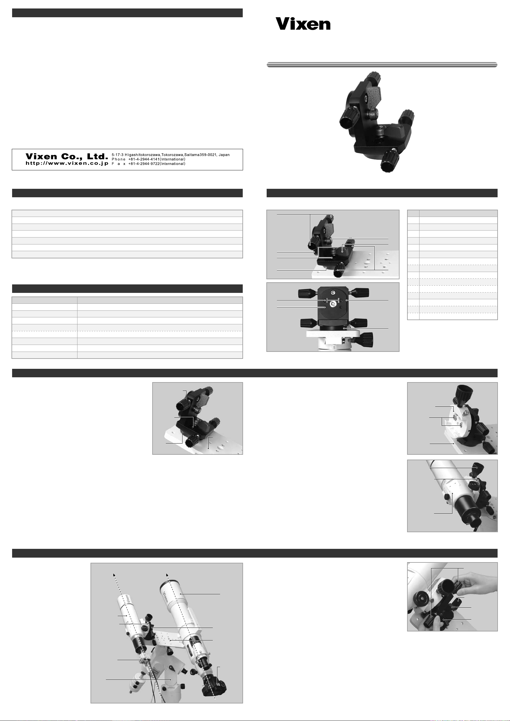
COMPONENTS
No.
①
④
⑤
②
❶
③
35mm distance35mm distance
❷
❸
⑥
②
③
Compo nents Guide
①
Altit ude (Vertical) Adjustment K nob
②
Mount ing Base (10mm thick)
③
Plate Attachment Base (10mm thick)
④
Altit ude (Vertical) Cl amp Lever
⑤
Azimu th (Horizontal) Clamp Lever
⑥
Azimu th (Horizontal) Adjustment Knob
❶
Holes for M8 screws
(at a n interval of 3 5mm)
❷
M8 Sc rew Holes
(10mm in depth, inte rval of 35mm),
for a ttaching a dove tail-plate moun ting
block and other appl ication
❸
M6 Sc rew Holes
(10mm in depth, inte rval of 35mm) f or
attac hing a dovetail tube plate dir ectly
ATTACHING THE GUIDE MOUNT XY
Attaching the Guide Mount XY to an accessory plate
This section describes the use of the Guide Mount XY with
the accessory plate DX and dovetail-plate mounting block.
Attach the main optical tube to the mount and set up the
telescope.
1
Attach the Guide Mount XY to the accessory plate DX as
shown. Fix the Guide Mount DX on the accessory plate DX
2
with the supplied M8x20mm screws so that the mounting
base surface of the Guide Mount XY is oriented in parallel to
the optical axis of the main telescope.
Mount ing Base
M8x20 mm
Screw s
Plate
Attac hment Ba se
Acces sory
Plate DX
Attach t he dovetail-plate mounting block to the mounting
base of the Guide Mount XY. Fix the dovetail-plate mounting
3
block firmly with the supplied M8x12mm screws.
Note: Do not attempt to use the M8x14mm screws that are
included in the dovetail-plate mounting block as accessories.
Those screws are too long to use.
Attach the dovetail mounted guide scope into the dovetail-
plate mountin g block and tighten the lock knob onto the
4
dovetail tube plate until secure.
Dovet ail-plat e
Mount ing Bloc k
M8x12 mm
Screw s
Acces sory
Plate DX
Lock knob
Safet y Screw
Guide Scope
The photo on the right shows
an example of a typical
autoguiding system with a
guide scope.
Guide Scope
Dovet ail-plat e
Mount ing Bloc k
CCD c amera
for a utoguidi ng
Mount
Paral let to e ach other
Main Scope
for I maging
Guide Mount X Y
Acces sory
Plate DX
Camer a
Using the Guide Mount XY
Loo sen on e side of the ad justment sc rew (knob) in the
direction where you will be moving the guide mount. Push
and move the guide mount slowly by turning the other side of
the adjustment screw (knob). The adjustment screws are
movable back and forth by +/- 6.5 degrees in the altitude and
azimuth directions.
Note: The tension of the adjustment screw can be changed
by further tightening the clamp lever; however, this may not
set it completely due to the tangent screws mechanism.
Altit ude
Adjus tment Kn obs
Azimu th
Adjus tment Kn ob
Altit ude
Clamp Lever
Azimu th
Clamp Lever
 Loading...