

Vivotek SD83x4E, SD83x6E, Supreme SD83xxE, Supreme SD83xxM, Supreme SD8363E Quick Installation Manual
Page 1
Speed Dome
SD83xxE/-M
Network Camera
Quick Installation Guide
English
Dansk
Indonesia
簡中
Français
Español Português
Deutsch
繁中 日本語
NEMA 4x • IP66 • Extreme Weatherproof
Italiano
Türkçe
Polski
Русский
Česky Svenska
Nederlands
Page 2
EN-1
English
Warning Before Installation
Refer to your user’s manual for the
operating temperature.
Power off the Network Camera as soon as
smoke or unusual odors are detected.
Do not touch the Network Camera during
a lightning storm.
Do not disassemble the Network Camera.
Do not drop the Network Camera.
Do not insert sharp or tiny objects into the
Network Camera.
Do not manually pan and tilt the Network
Camera when the power is on.
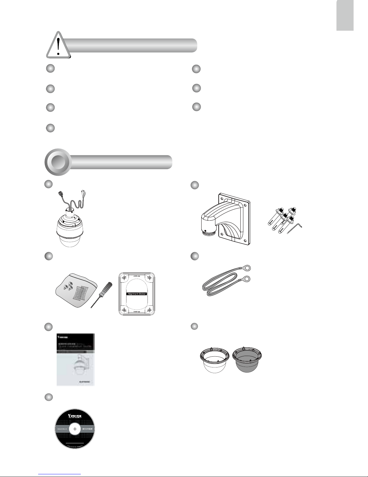
Package Contents
1
5
1
0
0
0
0
2
1
0
G
Software CD
Wall Mount Bracket / Screws
SD83xxE/-M (with extended cables)
Quick Installation Guide PC/ABS / Smoked Dome Cover
Screws / Alignment Sticker / T25
Stardriver / Desiccant Bags (SD8363E)
Ground Wire
Page 3
EN-2
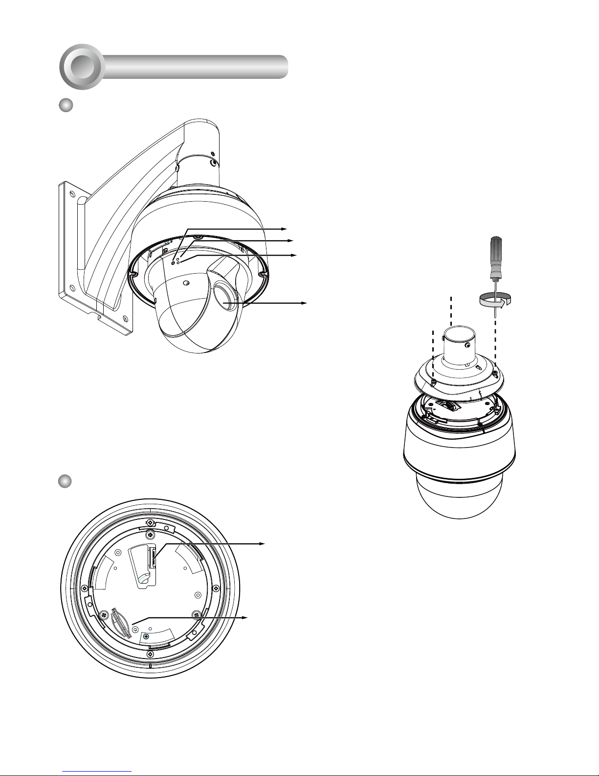
Inner View
Board-to-board
Connector
Lens
Outer View
Physical Description
2
SD/SDHC/SDXC Card Slot
Status LED
Network LED
Reset Button
Camera Body
This drawing shows a camera with its dome
cover removed.
The SD card slot is accessed by
removing the top section using the
T25 stardriver.
Page 4
EN-3
English
Hardware Installation
3
HD WDR Pro
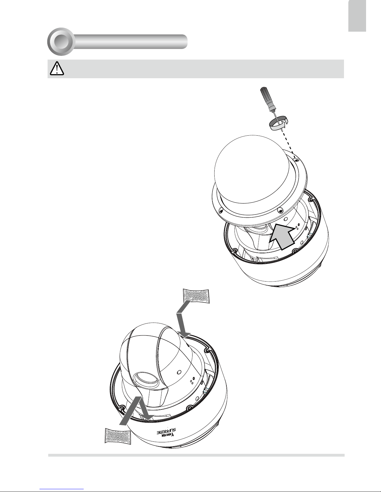
IMPORTANT:
If your camera comes without the dehumidier,
you should examine whether the color of the
silica gel inside the chassis has turned red. If
so, you should replace the desiccant bag.
To replace the desiccant bags:
1. Remove the dome cover by loosening 4 T25
anti-tamper screws.
2. Replace the desiccant bags by attaching
them rmly to the inside of the chassis.
3. Re-install the dome cover.
Also note the following:
1. Do not install the camera in a raining day.
2. It takes approximately 2 days to suppress
the moisture level to 30% or lower, either
using the desiccant bags or the dehumidier.
3. Condensation may still be observed from on
the dome cover within 30 minutes.
Page 5
EN-4
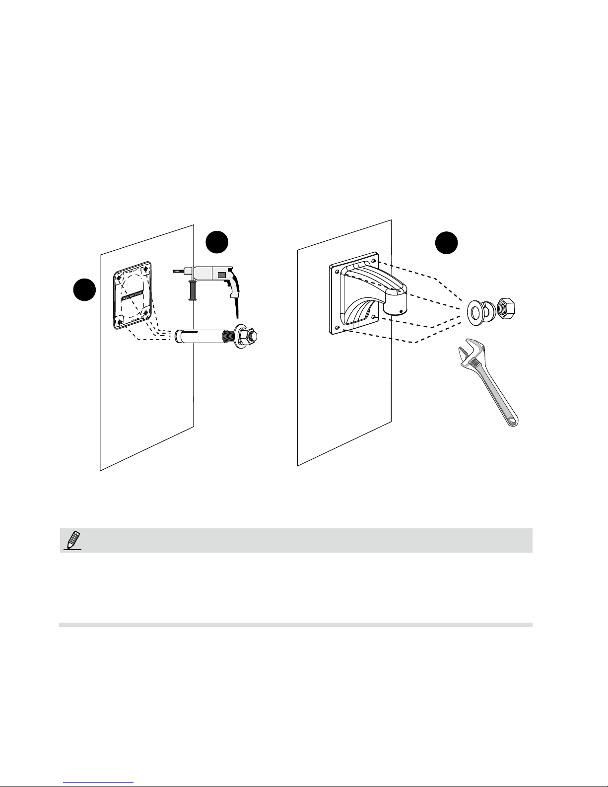
1. The camera weighs 3.66kg. Select a rigid mounting location to prevent vibration to
the camera. Attach the alignment sticker to the wall.
2. Drill 4 pilot holes (10mm in diameter and 4cm deep) into the wall, and then hammer in
threaded anchors. Note that you should hammer the anchors with hex nuts on them
so that the threaded poles will not be deformed! If preferred, drill another hole for
routing cables.
3. Secure the wall mount bracket to wall using 4 sets of captive washers and nuts.
1
2
3
3-1. Install the Wall-mount Bracket
1. IO wires are user-supplied.
2. Avoid touching the circuit boards to prevent damage by electro static discharge.
3. Use CAT5e, CAT6 cables only.
NOTE:
Page 6

EN-5
English
1
2
3
4
5
1. Hold your top section with one hand and pass all cables through the wallmount
bracket.
3-2. Cabling Connections & Attach the Top Section
2. Secure the top section to the wall mount bracket.
Note that you should turn and orient the top section so that the C mark is facing a
direction 15 degrees off the center line.
15°
Center line
C Mark
Remove seal from the breathe hole on
the top section if your camera comes with
the dehumidier.
Page 7
EN-6
3. Connect cables and use sealants and putties to make sure cable joints and the
cabling hole are waterproof.
4. Secure the included ground wire to the dome cap, pass it through the mount bracket, and connect the other end to a grounded conduit later.
5. Use the included hex wrench to secure the top section.
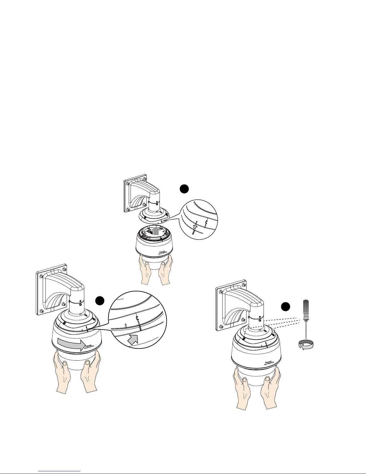
3-3. Mounting the Camera
4
2
3
1
HD WDR Pro
HD WDR Pro
HD WDR Pro
Alignment Mark
C Mark
1. Align the camera body with the top section. Align the alignment mark on the camera
with that on the interface section. Push the camera up to match the top section.
2. Rotate the camera clockwise until its alignment mark is aligned with the "C" mark.
3. Use the included T25 stardriver to tighten the 3 anti-tamper screws from the top.
Make sure all parts have been securely tightened.
Page 8
EN-7
English
Network Deployment
4
HD WDR Pro
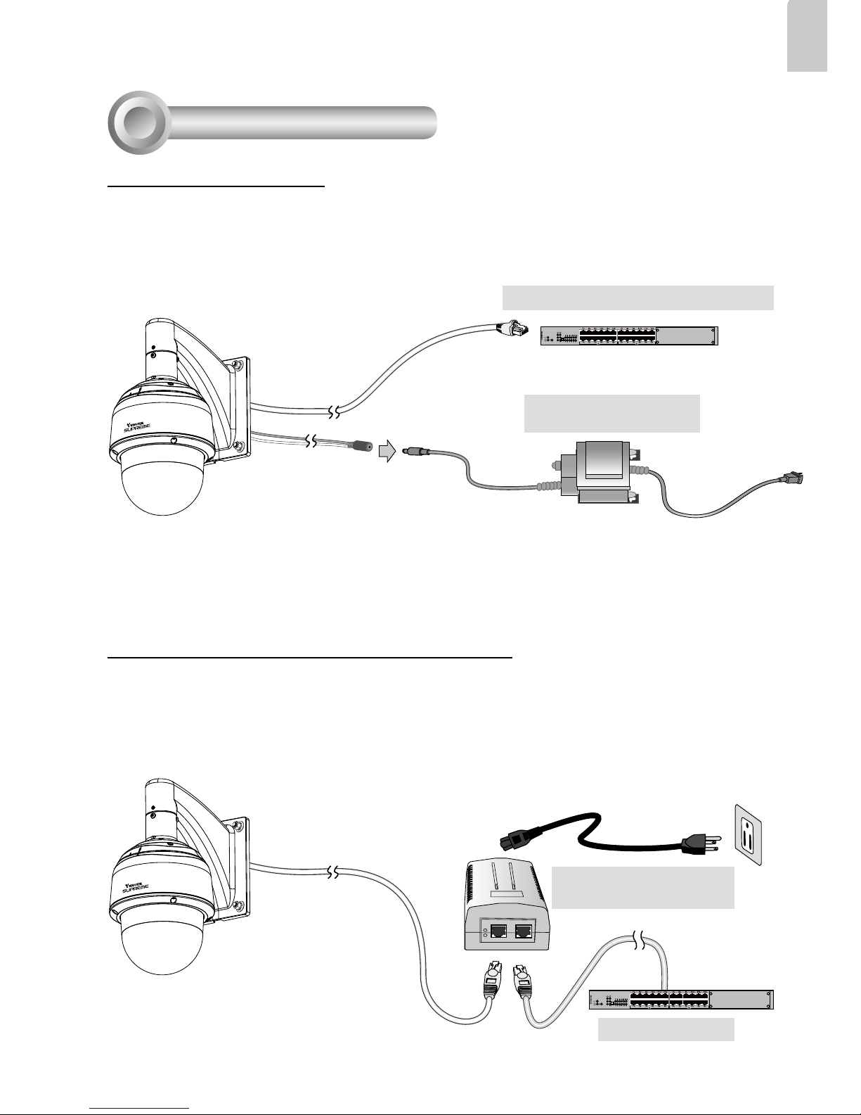
1. Connect the Network Camera's Ethernet cable (CAT5e, CAT6) to a PoE Plus switch. A
30W PoE output port alone can not drive the onboard heater, and hence if using the PoE
switch alone, the application does not apply in low-temperature condition. The 30W PoE
plus can only drive the camera when it is working at a temperature higher than -5ºC.
HD WDR Pro
When using a non-PoE switch
Use a High Power PoE power injector (separately purchased) capable of 60W output to
connect between the Network Camera and a non-PoE switch. Sufcient power is required
for low temperature conditions when the onboard heater is activated.
Non-PoE Switch
High Power PoE Power
Injector
2. Connect the power wires to an AC 24V power adaptor (user-supplied). The AC 24V
adapter can drive the camera and the onboard heater.
You can connect both power sources for redundancy in power supply.
Power over Ethernet (High Power PoE)
General Connection
AC 24V 3.5A Adapter
(User-supplied)
IEEE 802.3at PoE Switch (30W output)
and / or
Page 9
EN-8
1. Install "Installation Wizard 2" from the Software Utility directory on the software CD.
2. The program will conduct an analysis of your network environment. After your network
is analyzed, please click on the "Next" button to continue the program.
3. The program will search for VIVOTEK Video Receivers, Video Servers, and Network
Cameras on the same LAN.
4. After a brief search, the main installer window will pop up. Double-click on the MAC
address that matches the one printed on the camera label or the S/N number on the
package box label to open a browser management session with the Network Camera.
Assigning IP Address
5
For further setup, please refer to the user's manual on the software CD.
28x
Ready to Use
6
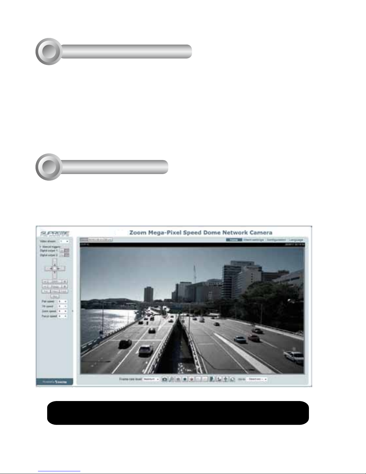
1. A browser session with the Network Camera should prompt as shown below.
2. You should be able to see live video from your camera. You may also install the
32-channel recording software from the software CD in a deployment consisting of
multiple cameras. For its installation details, please refer to its related documents.
Page 10

Page 11

P/N:625019001G Rev.: 1.1
All specications are subject to change without notice.
Copyright 2014 VIVOTEK INC. All rights reserved.
c
VIVOTEK INC.
6F, No.192, Lien-Cheng Rd., Chung-Ho, New Taipei City, 235, Taiwan, R.O.C.
VIVOTEK Netherlands B.V.
Busplein 36, 1315KV, Almere, The Netherlands
VIVOTEK USA, INC.
2050 Ringwood Avenue, San Jose, CA 95131
 Loading...