

Page 1
User’s Manual
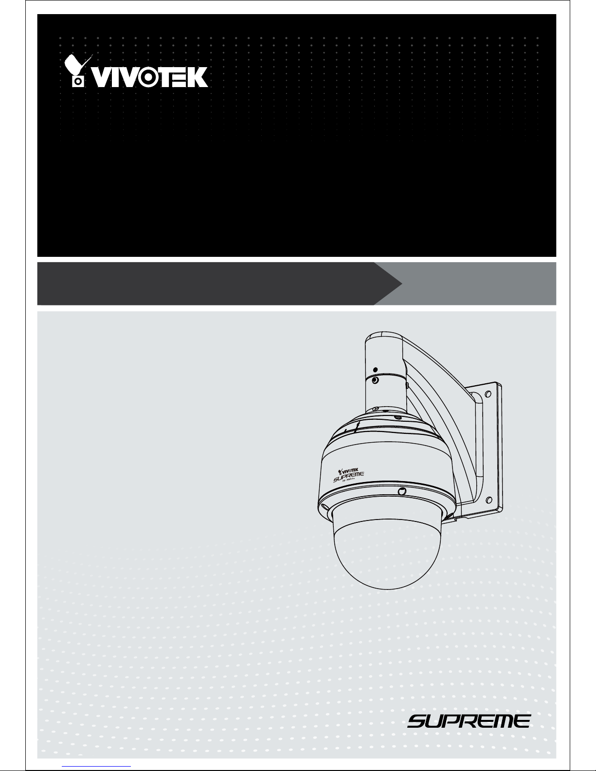
SD8363E/63E-M
Speed Dome
Network Camera
1080P • 20x Zoom • NEMA 4x • IP66 •
Extreme Weatherproof
Rev. 1.0
Page 2

VIVOTEK
2 - User's Manual
Table of Contents
Overview.......................................................................................................................................................4
Revision History ......................................................................................................................................4
Read Before Use ..................................................................................................................................... 5
Package Contents ................................................................................................................................... 5
Symbols and Statements in this Document ............................................................................................. 5
Physical Description
............................................................................................... 6
Installation ....................................................................................................................................................9
Hardware Installation
..................................................................................................... 9
Network Deployment ............................................................................................................................. 18
Software Installation .............................................................................................................................. 21
Ready to Use ......................................................................................................................................... 22
Accessing the Network Camera .................................................................................................................23
Using Web Browsers .............................................................................................................................23
Using RTSP Players ..............................................................................................................................25
Using 3GPP-compatible Mobile Devices ............................................................................................... 26
Using VIVOTEK Recording Software .................................................................................................... 27
Main Page ..................................................................................................................................................28
Client Settings ............................................................................................................................................34
Conguration ..............................................................................................................................................39
System > General settings ....................................................................................................................40
System > Homepage layout .................................................................................................................42
System > Logs ......................................................................................................................................45
System > Parameters ........................................................................................................................... 46
System > Maintenance .......................................................................................................................... 47
Media > Image ....................................................................................................................................51
Media > Video .......................................................................................................................................61
Media > Audio........................................................................................................................................ 65
Network > General settings ................................................................................................................... 66
Network > Streaming protocols ...........................................................................................................74
Network > DDNS ................................................................................................................................. 78
Network > SNMP (Simple Network Management Protocol) ..................................................................83
Security > User Account ........................................................................................................................ 84
Security > HTTPS (Hypertext Transfer Protocol over SSL) ........................................................85
Security > Access List .........................................................................................................................92
PTZ > PTZ settings ..............................................................................................................................97
Event > Event settings ........................................................................................................................102
Applications > Motion detection........................................................................................................... 116
Applications > DI and DO .................................................................................................................. 119
Applications > Audio detection ..........................................................................................................120
Recording > Recording settings .........................................................................................................122
Local storage > SD card management ................................................................................................ 127
Page 3

VIVOTEK
User's Manual - 3
Local storage > Content management ............................................................................................................... 128
Appendix ................................................................................................................................................................. 130
URL Commands for the Network Camera .......................................................................................................... 130
Technical Specications ..................................................................................................................................... 216
Technology License Notice ................................................................................................................................. 217
Electromagnetic Compatibility (EMC) ................................................................................................................. 218
Page 4

VIVOTEK
4 - User's Manual
Overview
VIVOTEK SD8363E is part of the SUPREME series product line offering 1080p Full HD
resolution with superb image quality. Adopting a 20x optical zoom lens, the SD8363E is able
to capture details at top-notch quality. The IP66- and NEMA 4X-rated housing protects the
camera body against rain, dust, and corrosion within a wide temperature range of between
-40°C to 55°C. This feature ensures operation under extreme weather conditions and hazardous
environments. It is especially suitable for monitoring wide open indoor/outdoor spaces such as
airports, highways and parking lots where high-level reliability and precision are always required.
The SD8363E supports high-performance H.264/MPEG-4/MJPEG compression technology
and offers extra smooth video quality with resolution up to 30 fps @ 1080p. Boasting WDR Pro
technology, the SD8363E can also cope with challenging lighting conditions and generate image
quality close to the capabilities of the human eye. With a sophisticated pan/tilt mechanism, the
camera provides fast, precise movement with continuous 360-degree pan and 220-degree tilt.
Users can also easily control the lens position via a mouse or a joystick to track the object of
interest and set up to 256 preset positions for patrolling. With the built-in auto tracking feature,
the SD8363E provides instantaneous reaction to suspicious moving objects in wide area locations
before operators are aware of activity.
As with all VIVOTEK true day/night cameras, the SD8363E features a removable IR-cut lter,
maintaining clear images 24 hours a day. With audio detection, by recognizing increases
or decreases in sound volume, an additional layer of intrusion detection is ensured. Zoom
enhancement provides 60x optical zoom at 640x360 resolution by which VGA-level bandwidth
is used to obtain image details as high as 1080p resolution. With other advanced features such
as SD/SDHC/SDXC card slot, 802.3at compliant PoE Plus and 60 fps high quality video, the
SD8363E is the best choice for the most demanding outdoor surveillance applications.
Revision History
■ Rev. 1.0: Initial release
Page 5
VIVOTEK
User's Manual - 5
Read Before Use
The use of surveillance devices may be prohibited by law in your country. The Network Camera is not
only a high-performance web-ready camera but can also be part of a exible surveillance system. It is
the user’s responsibility to ensure that the operation of such devices is legal before installing this unit for
its intended use.
It is important to rst verify that all contents received are complete according to the Package Contents
listed below. Take note of the warnings in the Quick Installation Guide before the Network Camera is
installed; then carefully read and follow the instructions in the Installation chapter to avoid damage due to
faulty assembly and installation. This also ensures the product is used properly as intended.
The Network Camera is a network device and its use should be straightforward for those who have basic
networking knowledge. It is designed for various applications including video sharing, general security/
surveillance, etc. The Configuration chapter suggests ways to best utilize the Network Camera and
ensure proper operations. For creative and professional developers, the URL Commands of the Network
Camera section serves as a helpful reference to customizing existing homepages or integrating with the
current web server.
Package Contents
■ SD8363E/63E-M (-M species the camera that comes with a dehumidier unit)
■ Wall Mount Bracket / Screws
■ Waterproof Connectors / Terminal Blocks / Ethernet Cable / Ground Wire
■ Screws / Alignment Sticker / T25 Stardriver / Seal Ring / Desiccant Bags
■ Quick Installation Guide
■ Software CD / Warranty Card
■ PC/ABS /Smoked Dome Cover / IO Combo Cable (Separately Purchased)
Symbols and Statements in this Document
i
INFORMATION: provides important messages or advices that might help prevent inconvenient
or problem situations.
NOTE: Notices provide guidance or advices that are related to the functional integrity of the
machine.
Tips: Tips are useful information that helps enhance or facilitae an installation, function, or
process.
WARNING! or IMPORTANT!: These statements indicate situations that can be dangerous or
hazardous to the machine or you.
Electrical Hazard: This statement appears when high voltage electrical hazards might occur
to an operator.
Page 6
VIVOTEK
6 - User's Manual
Physical Description
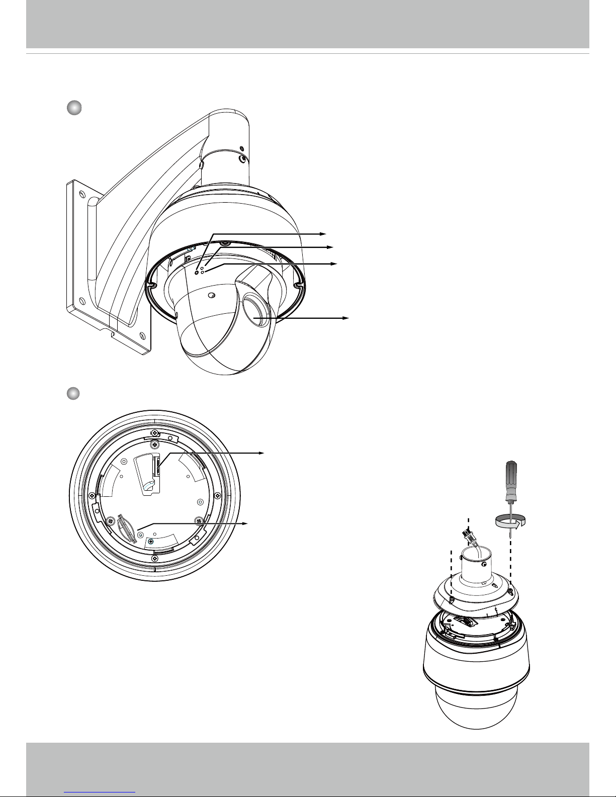
Lens
Outer View
Status LED
Network LED
Reset Button
This drawing shows a camera with its dome cover
removed.
Inner View
Board-to-board Connector
SD/SDHC/SDXC Card Slot
Camera Body
The card slot is accessed by removing the top
section using the T25 stardriver.
Page 7
VIVOTEK
User's Manual - 7
Status LED
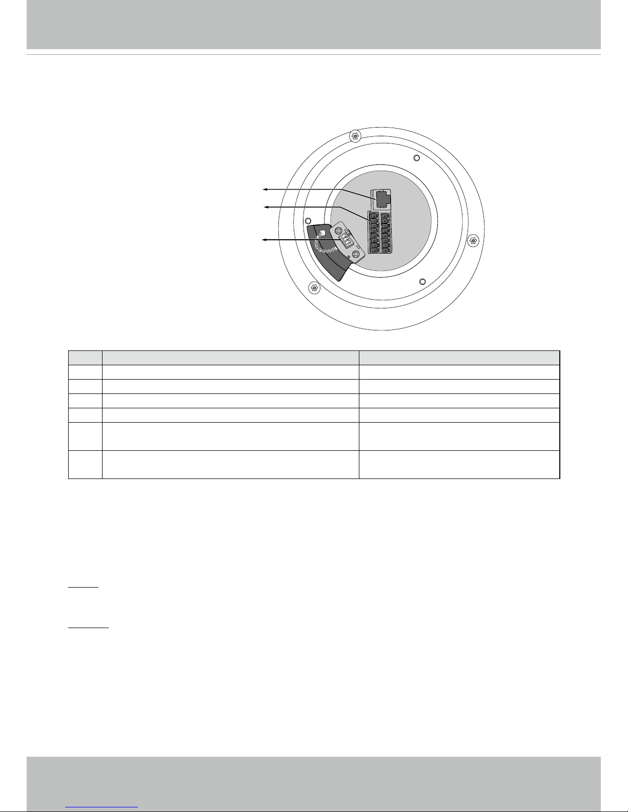
Item LED status Description
1 Steady red Power on and system booting
Red LED off Power off
2 Steady red & Green blinking every 1 sec. Network normal (heartbeat)
Steady red & Green LED off Network failed
3 Red blinking every 0.15 sec. & Green blinking
every 1 sec.
Upgrading rmware
4 Red blinking every 0.15 sec. & Green blinking
every 0.15 sec.
Restoring default
Hardware Reset
The reset button is used to reset the system or to restore the factory default settings. Sometimes
resetting the system can return the camera to normal operation. If the system problems remain
after reset, restore the factory settings and install again.
Reset: Press and release the recessed reset button with a paper clip or thin object. Wait for the
Network Camera to reboot.
Restore: Press and hold the recessed reset button for a while to restore. Note that all settings
will be restored to factory default.
SD/SDHC/SDXC Card Capacity
This network camera is compliant with SD/SDHC/SDXC 32GB, 64GB, and other preceding
standard SD cards.
Ethernet 10/100 RJ45 Plug
Spring Contacts for Dehumidier
General I/O Terminal Block
Ethernet
DI GND
DI4
DI3
DI2
DI1
DO2
DO1
DO+(12V)
AC24V
AC24V
Reserved
MIC IN
Line OUT
Audio GND
RS485-
RS485+
Interface Section
Page 8
VIVOTEK
8 - User's Manual
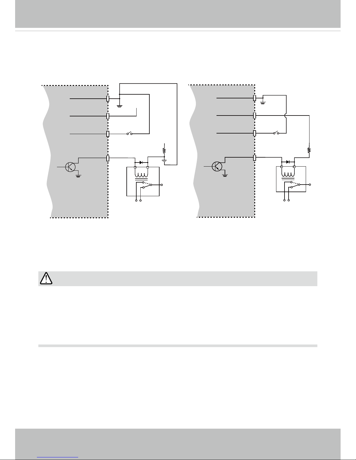
DI/DO Diagram
Please refer to the following illustration for the connection method. Please note that the
maximum load on the DO pins is 50mA.
Gnd
Camera Power
Input
Output
+12
VDC
Max.
VDC
Switch
BJT transistor
Gnd
Camera Power (DO+ 12V)
Input
Output
+12
VDC
VDC
Switch
BJT transistor
Relay
Relay
1. The camera can be driven by an Ethernet connection to a PoE Plus switch (30W output). You
can connect both the PoE Plus and the 24V power for fail-safe redundancy.
2. If the installation requires heating in the winter (<-5ºC), you require approximately 60 Watts of
power to drive the embedded heater. You can either connect the 24V power lines or a High
Power PoE power injector (separately purchased).
IMPORTANT:
Page 9
VIVOTEK
User's Manual - 9
Installation
Hardware Installation
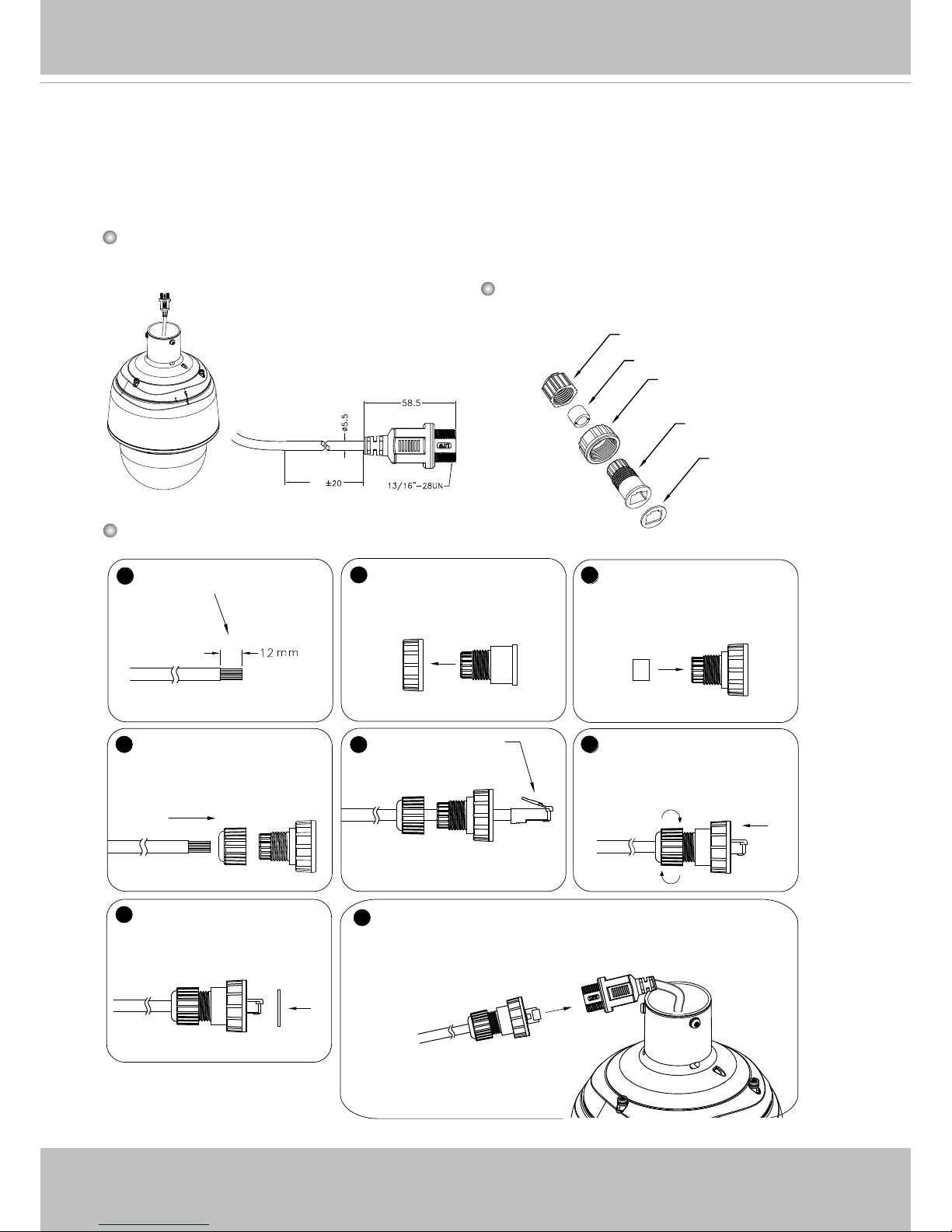
RJ45 Cable Dimension (unit: mm)
Use CAT5e cables only.
1. Connecting RJ45 Ethernet Cable
1
2
3
4
5
6
7
8
(D)
(B)
(C)
(A)
(E)
Components of the Waterproof
Connector
Screw Nut (C)
Housing (D)
Gasket (E)
Seal (B)
Sealing Nut (A)
100
Prepare an Ethernet cable
and strip part of the sheath.
Insert the housing into the
screw nut.
Insert the seal into the housing.
Insert the stripped Ethernet
cable through the sealing nut
and the housing.
Clamp the cable with
an RJ45 plug.
Push the RJ45 plug into
the housing, then secure
the sealing nut tightly.
Attach the gasket to the
front of the housing.
Assembling Steps
Recommended cable gauge: O.D. 5.5~7
Connect the Ethernet cable to the RJ45 cable and secure
the connectors tightly.
Page 10
VIVOTEK
10 - User's Manual
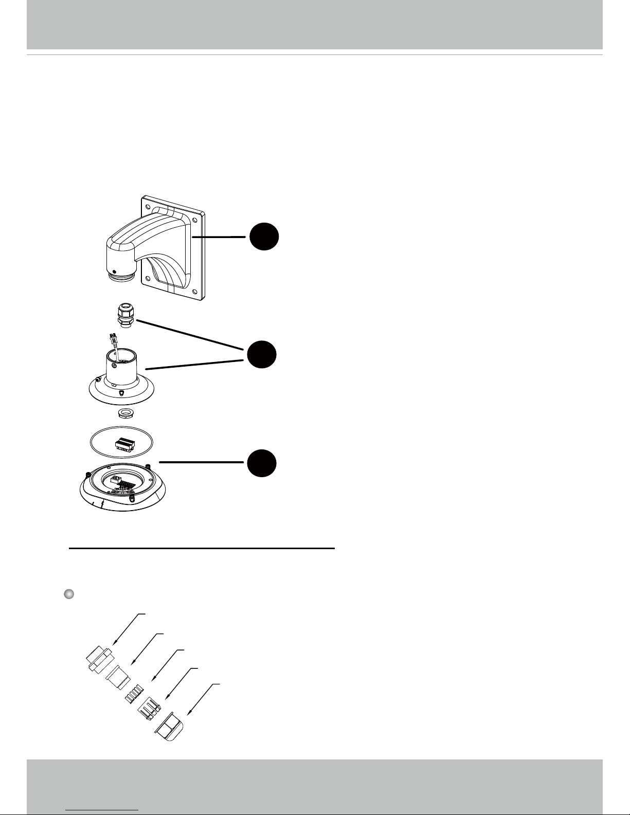
2. Connecting Power and I/O Wires
If you need to connect I/O wires and 24V power, disassemble the top section of the camera. It is
highly recommended to complete the following before you can mount the speed dome camera at the
installation site:
Skip this section and move to Section 3-3 if you connect the Ethernet cable only.
1-3
1-2
1-1
Plan the wire length and complete cabling to the
Interface Section
Cabling through the dome cap and waterproof
connectors
Connect with the mount bracket
2-1. Cabling through the Waterproof Connectors
Components of the Waterproof Connector
Seals (C)
Housing (D)
Sealing Nut (E)
Seal (B)
Screw Nut (A)
•
Wire range: 13~16AWG (1.2~1.8mm)
•
A socket wrench for the M20 hex nut is required.
Page 11
VIVOTEK
User's Manual - 11
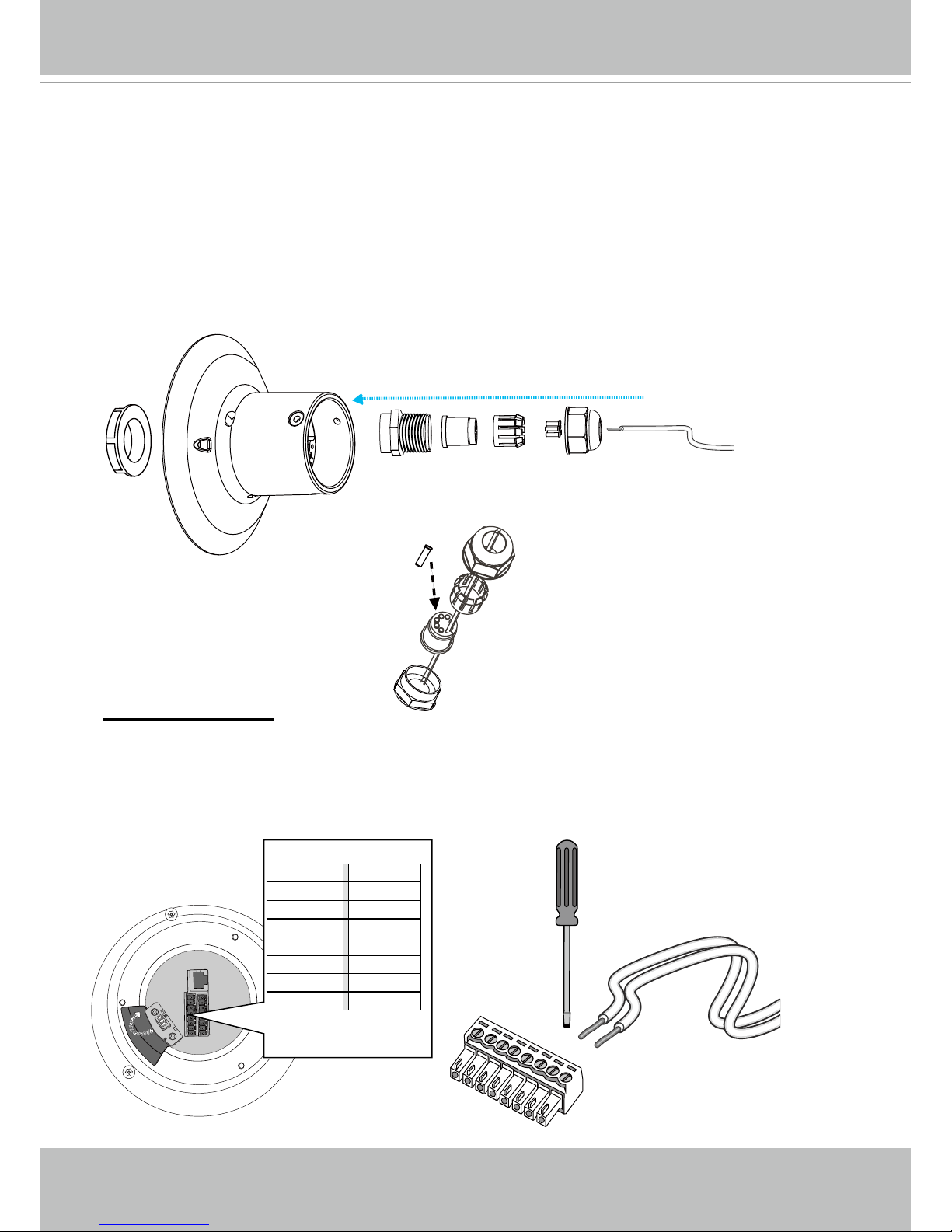
1. Disassemble the components of the waterproof connector into parts (A) ~ (E) as
shown above.
2. Remove the plastic stopper from the bottom of the dome cap and keep the M20 hex
nut for later use.
3. Depending on the number of wires, remove seals (C) from the rubber seal (B).
4. If you have external devices such as sensors and alarms, feed IO wires through the
waterproof connector (E --> D --> B --> A) as the illustrated below. Note that there are
16 holes on the seal (B), and wire range is beteen 1.2 and 1.8mm.
5. Push the seal (B) into the housing (D).
6. Secure the sealing nut (E) tightly.
(E)(D)(B)(A)
(C)
(B)
(D)
2-2. Connect cables:
Ethernet
DI GND
DI4
DI3
DI2
DI1
DO2
DO1
DO+(12V)
AC24V
AC24V
Reserved
MIC IN
Line OUT
Audio GND
RS485-
RS485+
AC24V DI GND
AC24V DI4
Reserved DI3
MIC IN DI2
Line OUT DI1
Audio GND DO2
RS485- DO1
RS485+ DO+(12V)
Wire range: 13~16AWG
Strip length: 6~7mm
Screw: M2
1. Use a small-size at-blade screwdriver to secure IO
wires to the included terminal blocks. You may also
purchase an IO combo cable from VIVOTEK.
M20 hex
nut
Page 12
VIVOTEK
12 - User's Manual
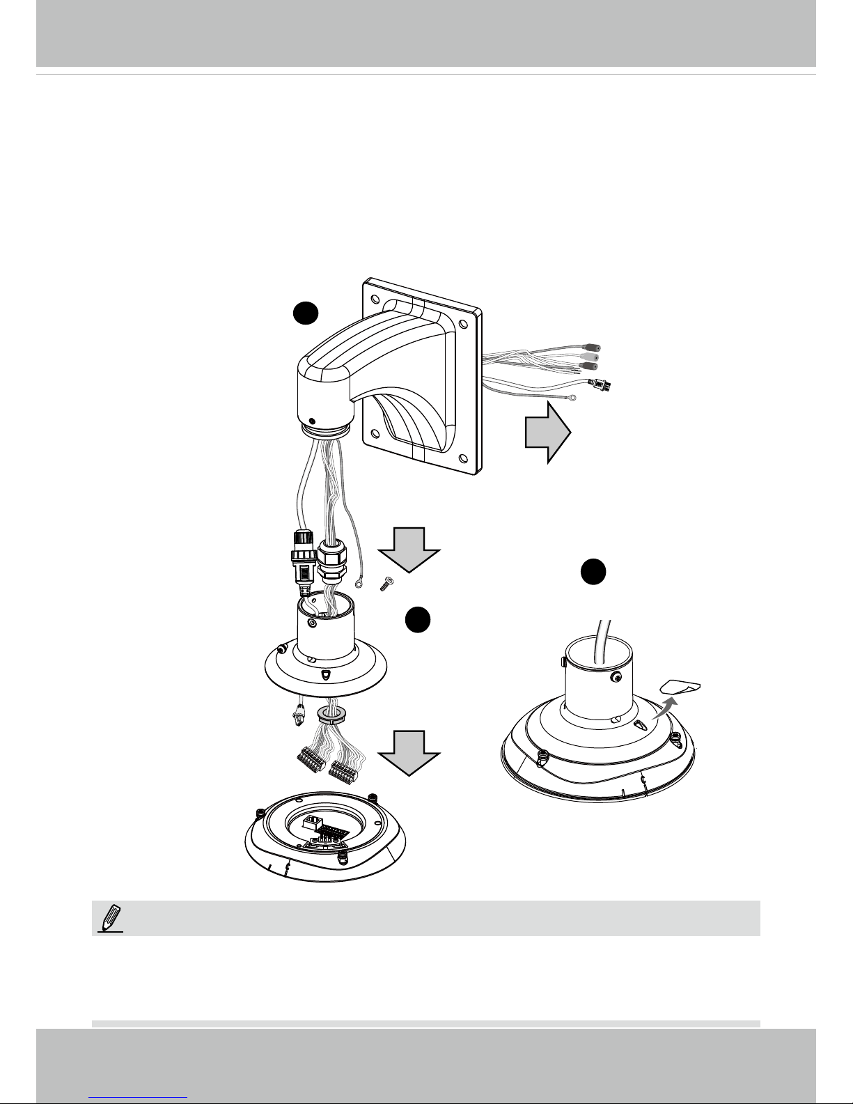
2. Feed the Ethernet cable and IO wires through the mounting bracket, the openings on the
dome cap, and to the interface section. Attach the rubber seal plug to dome cap for water
proong.
1. IO wires are user-supplied.
2. Avoid touching the circuit boards to prevent damage by electro static discharge.
NOTE:
3. Secure the included ground wire to the dome cap, pass it through the mount bracket, and connect the other end to a grounded conduit later.
4. Remove seal from the breathe hole on the top section if your camera comes with the dehu-
midier.
Mount bracket
Dome cap
Interface Section
2
3
4
Page 13
VIVOTEK
User's Manual - 13
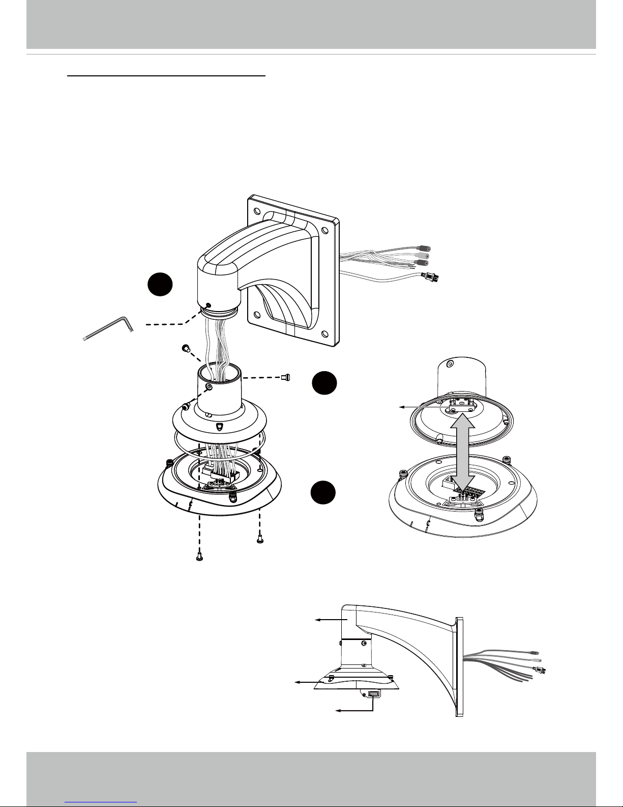
Combine the components of the top section.
1. Press the seal ring into the groove on the interface section. Use the black machine screws
(M4x8) to attach the interface section to the dome cap. Note that you should orient and align
the spring contacts with the dehumidier unit on the dome cap.
2. Secure the dome cap to the mount bracket.
3. Use the included hex wrench to secure the connection.
When done, the top section will look
like this. You can now carry the camera and the top section
to the installation site.
Mount
Bracket
Interface Section
Board-to-board
Connector
Dehumidier Unit
1-3. Connect with the Mount Bracket
1
2
3
Seal Ring
Page 14

VIVOTEK
216 - User's Manual
Electromagnetic Compatibility (EMC)
FCC Statement
This device compiles with FCC Rules Part 15. Operation is subject to the following two conditions.
■ This device may not cause harmful interference, and
■ This device must accept any interference received, including interference that may cause undesired
operation.
This equipment has been tested and found to comply with the limits for a Class A digital device, pursuant
to Part 15 of the FCC Rules. These limits are designed to provide reasonable protection against
harmful interference when the equipment is operated in a commercial environment. This equipment
generates, uses, and can radiate radio frequency energy and, if not installed and used in accordance
with the installation manual, may cause harmful interference to radio communications. Operation of this
equipment in a residential area is likely to cause harmful interference, in which case the user will be
required to correct the interference at his own expense.
CE Mark Warning
This is a Class A product. In a domestic environment, this product may cause radio interference, in which
case the user may be required to take adequate measures.
VCCI Warning
この装置は、情報処理装置等電波障害自主規制協議会(VCCI)の基準にづくクラスB情報技術装置です。この
装置は、家庭環境で使用することを目的としていますが、この装置がラジオやテレビジョン受信機に近接して使
用されると、受信障害を引き起こすことがあります。
取扱説明書に従って正しい取り扱いをして下さい
Liability
VIVOTEK Inc. cannot be held responsible for any technical or typographical errors and reserves the right
to make changes to the product and manuals without prior notice. VIVOTEK Inc. makes no warranty
of any kind with regard to the material contained within this document, including, but not limited to, the
implied warranties of merchantability and fitness for any particular purpose.
 Loading...