

Page 1
Page 2
EN - 1
English
Warning Before Installation
Package Contents
1
Power off the Network Camera as
soon as smoke or unusual odors
are detected.
Refer to your user’s manual for the
operating temperature.
Do not place the Network Camera
on unsteady surfaces.
Do not touch the Network Camera
during a lightning storm.
Do not insert sharp or tiny objects
into the Network Camera.
Do not drop the Network Camera.
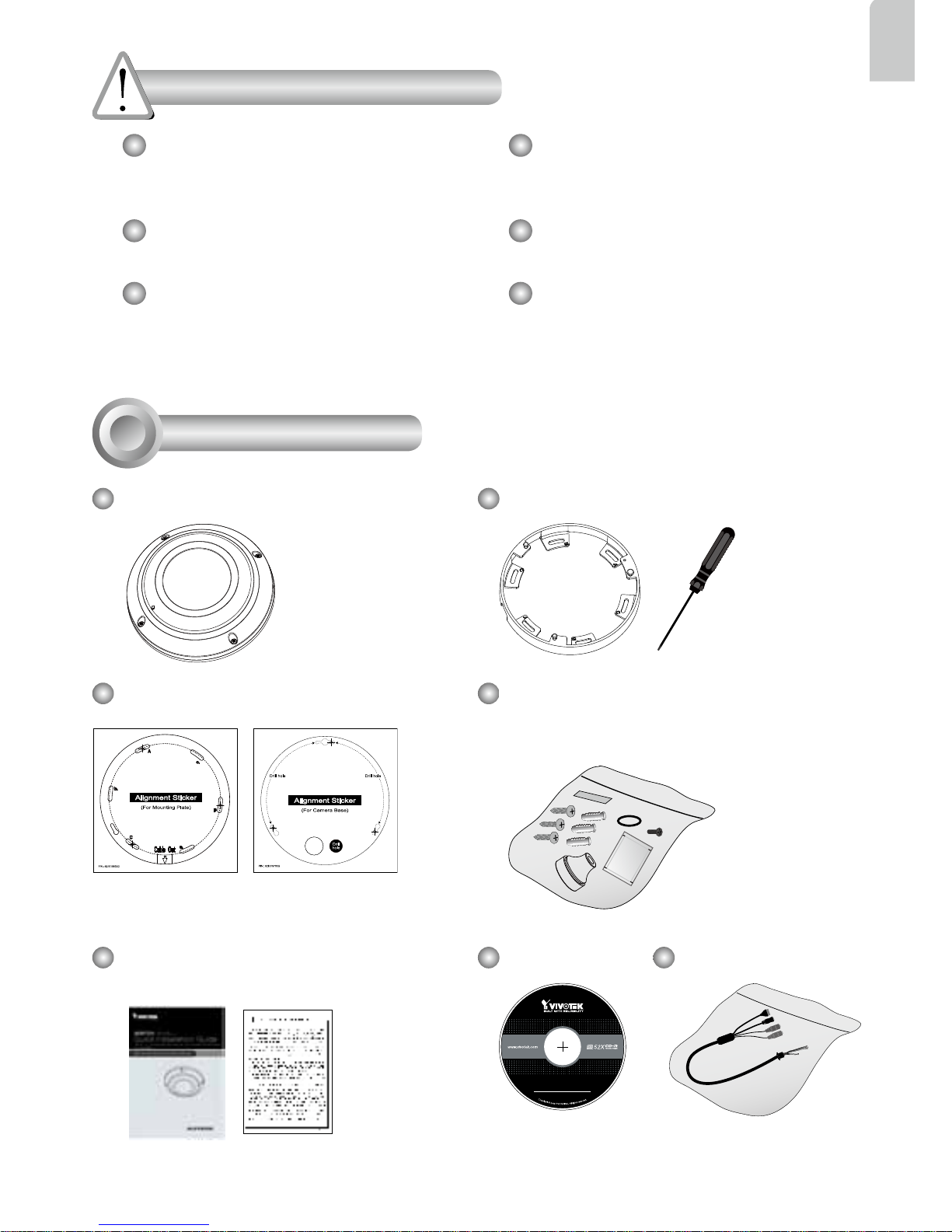
SF8172V Mounting Plate / Screwdriver
Alignment Stickers
For Mounting Plate For Camera Base
Screws / Desiccant Bag /
Double-sided Tape / Rubber Seal
Plug / Rubber Washer
Quick Installation Guide /
Warranty Card
Software CD
5
1
0
0
0
0
2
1
0
G
Power & I/O Cables
Page 3
EN - 2
Physical Description
2
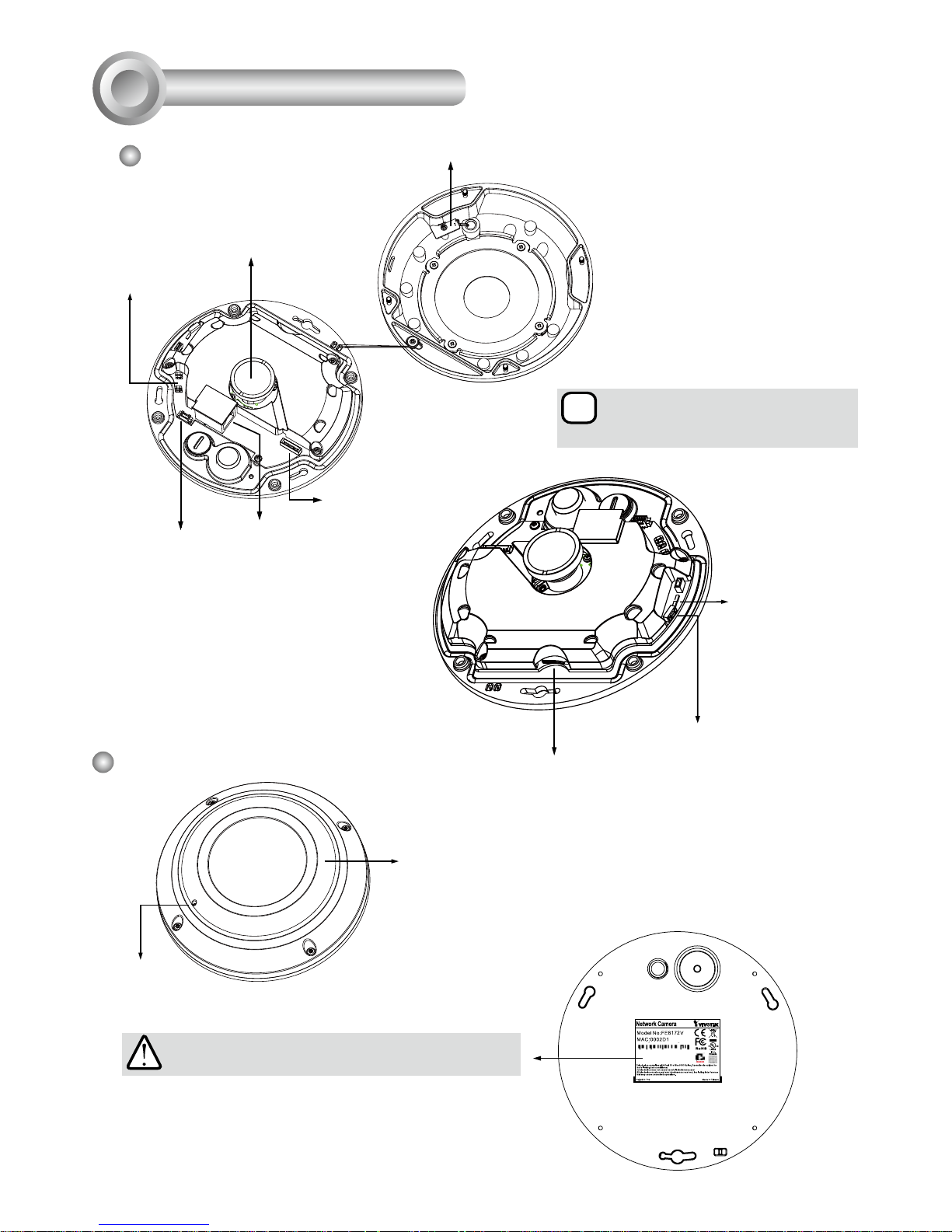
Header (J7)
Spring Contacts (A)
Lens
Contacts for Internal Microphone (B)
Header (J6)
Ethernet 10/100 RJ45
Socket
i
Align (B) to (A) when
attaching the dome cover
MicroSD/SDHC/SDXC Card Slot
Reset Button
Status LEDs
083236
Outer View
Built-in Microphone
IP66-rated Vandal-proof
Dome Cover
IMPORTANT:
Record the MAC address under the camera base
before installing the camera.
Inner View
Page 4
EN - 3
English
Hardware Installation
3
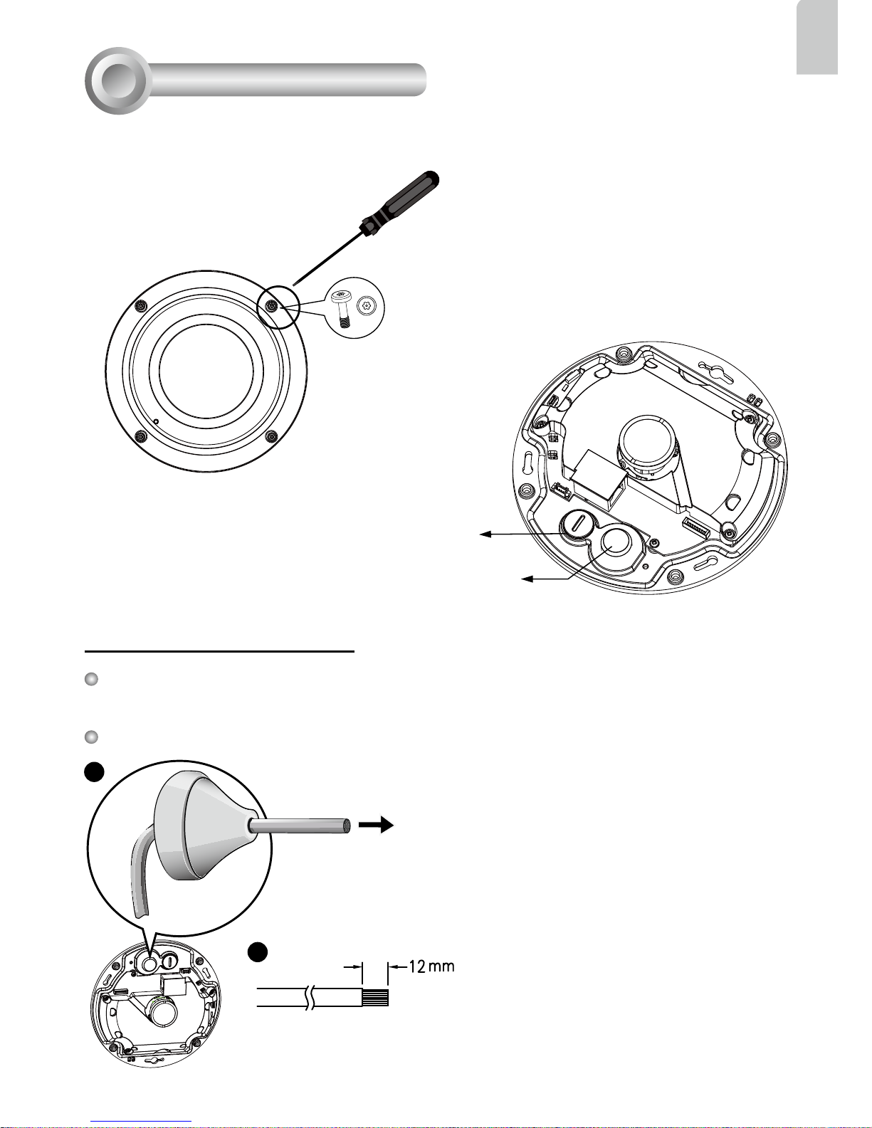
Rubber Stopper on the hole for
Power & IO Cables
Tamper-proof Screw
Rubber Seal Plug on the hole
for RJ45 Ethernet Cable
First, use the supplied screwdriver to loosen the four screws and detach the dome cover from the
camera base. Then, follow the steps below to install the camera to either a ceiling or a wall.
Remove the stoppers and route cables through the
openings.
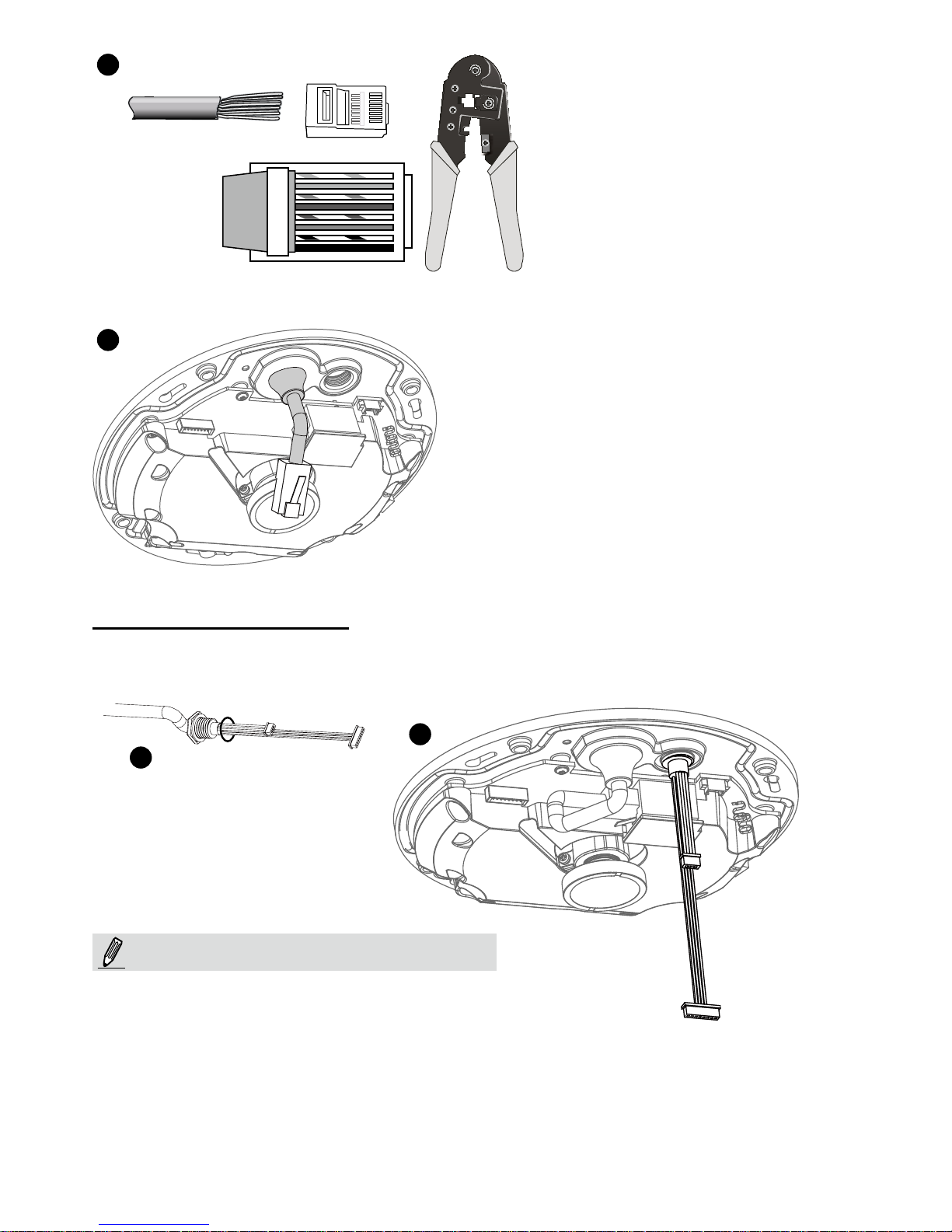
2. Strip part of the sheath from the Ethernet
cable.
1. Drill a hole on the rubber seal plug and insert
an Ethernet cable through the opening.
Connecting RJ45 Ethernet Cable
RJ45 Cable Dimension (unit: mm)
Recommended cable gauge: 24AWG (0.51 mm)
Assembly Steps
Rubber Seal
Plug
1
2
Page 5
EN - 4
3. You will need an RJ45 crimping tool to
attach the Ethernet wires to a connector.
When done, connect the cable to the
camera’s Ethernet RJ45 socket.
o
O
g
B
b
G
br
BR
1
2
3
4
5
6
7
8
3
4
4. Feed the Ethernet cable from the bottom of the
camera and through the hole. Attach the rubber seal
plug for water proofing.
Connecting DC Power Cable
1. Add the supplied rubber washer to the cable as shown in the picture.
2. Feed the cable from the bottom of the camera and tighten the plastic base for waterproofing.
o: white/orange stripe
O: orange solid
g: white/green stripe
B: blue solid
b: white/blue stripe
G: green solid
br: white/brown stripe
BR: brown solid
1
2
Connect the supplied power & IO cables if
your switch does not support PoE.
NOTE:
Page 6
EN - 5
English
Ceiling Mount Installation
Hole marked as D+
D
D
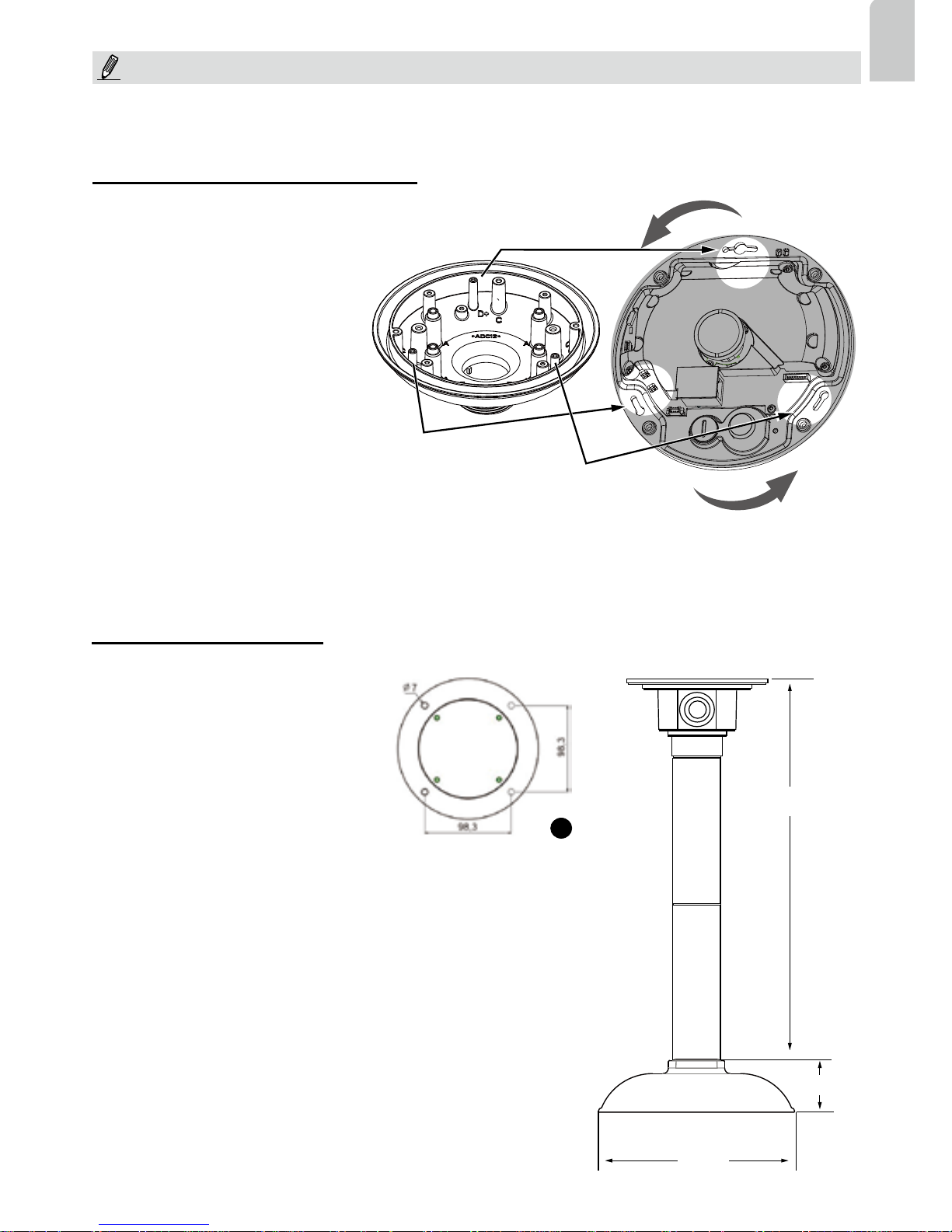
To attach the camera to AM-51A
mounting adaptor,
1. Remove the camera's top cover.
2. Fasten 2 included screws to the D
holes (not the D+ hole).
3. Route cables through the adapter.
4. Align the camera with the
mounting adapter and let the 2
screws enter the key holes located
on the sides where the camera's
cabling interfaces reside, e.g., the
Ethernet port.
5. Rotate the camera counterclockwise. You can then see the
D+ hole through the slotted screw
hole (in front of the Micro SD slot).
6. Fasten screws to secure the
camera to the mounting adapter.
456 mm
1
178 mm
47mm
AM-116
AM-116
AM-51A
AM-114
Attach Camera to Mounting Adapter
Install the Pendant Pipe
Below is a sample procedure using a
pendant pipe:
1. Determine a hard surface ceiling
location, and use the four mounting
holes on the pendant head to mark
the positions where holes will be
drilled to secure the pendant head.
Note that screws are user-supplied
and they should be at least 11mm
long.
2. Route cables through the pendant
pipe and the pendant head.
IMPORTANT:
Refer to the "Panoramic PTZ Installation Guide" in your product CD for design considerations before
you proceed with physical installation.
Page 7
EN - 6
30~100cm
AM1010
NOTE:
Header (J7)
Header (J6)
1
2
7
4
3
5
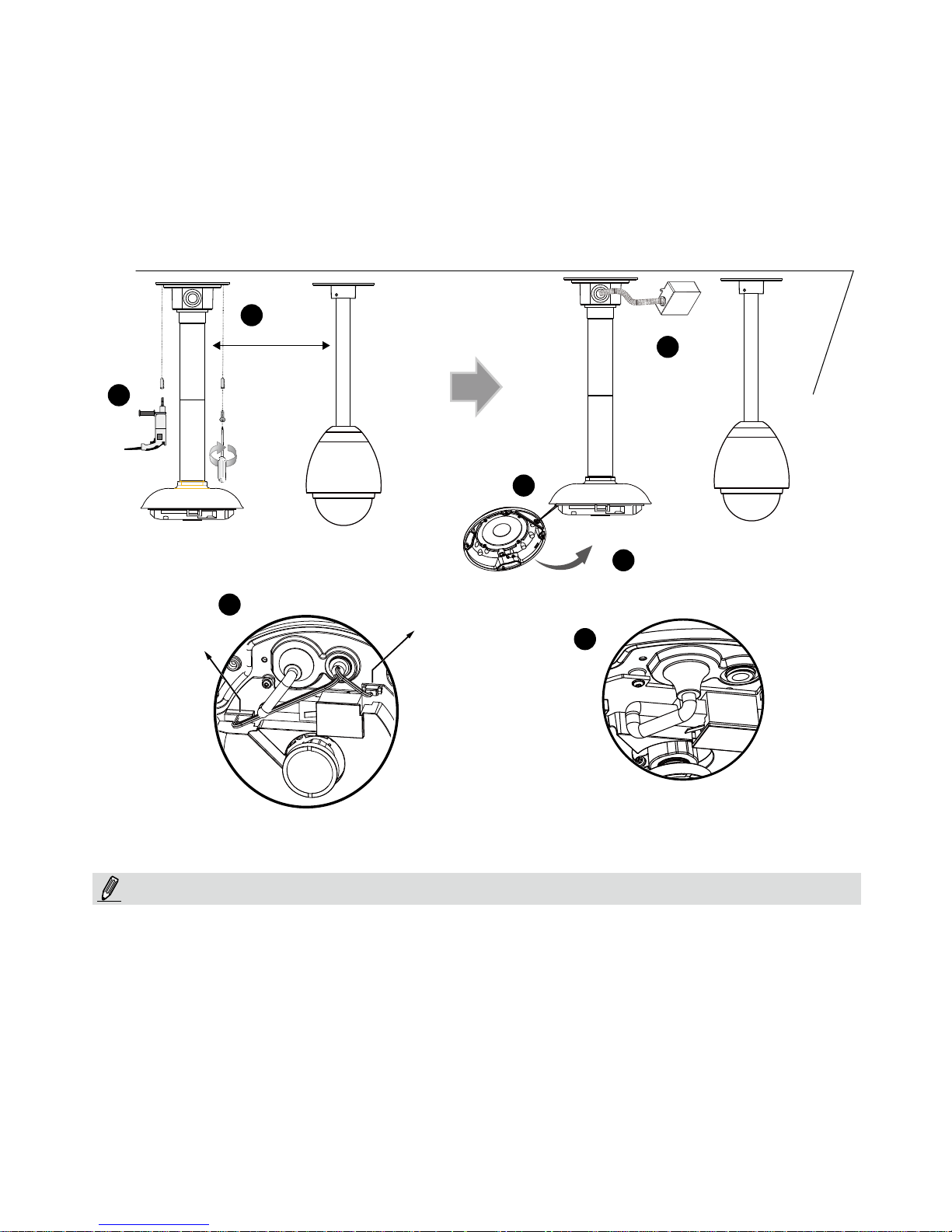
Install to the Ceiling
1. Drill pilot holes into the ceiling. Then hammer four anchors into the holes.
2. Secure the pendant head to the ceiling using four screws.
3. Connect the two white header connectors to the J6 and J7 connectors.
4. Connect the Ethernet cable to the RJ-45 socket.
5. You will find a desiccant bag attached to the camera. Replace the desiccant bag included in the
camera with the one shipped within the accessory bag.
6. Attach the dome cover to the camera by driving its anti-tamper screws.
7. Route cables through a 3/4” conduit from the pendant head.
Arrange the cables neatly to avoid getting in the way when the dome cover is attached.
6
Page 8
EN - 7
English
1
2
3
6
AM-51A
AM-116
AM-212
4
5
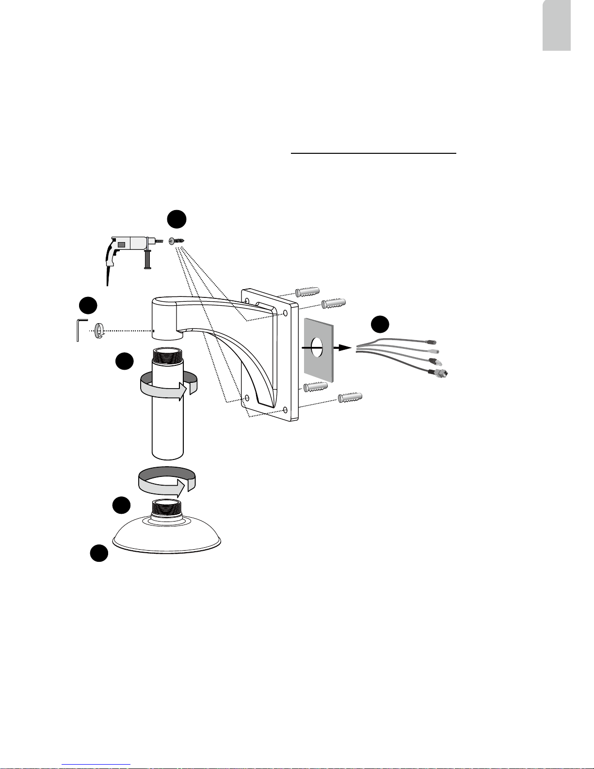
Wall Mount Bracket Installation
Below is a sample procedure using a wall mount bracket and a pendant pipe:
1. Determine a hard surface ceiling location. Use the four mounting holes on the wall mount bracket
to mark the positions where holes will be drilled to secure the bracket and routing cables. Note that
screws are user-supplied and they should be at least 11mm long.
2. Feed cables through the bracket.
3. Install the pendant pipe.
4. Install the camera to the mounting adapter. See Attach Camera to Mounting Adapter on the previous
page.
5. Install the mounting adapter to pendant pipe.
6. Tighten the connection using the included hex wrench.
Page 9
EN - 8
Network Deployment
30~100cm
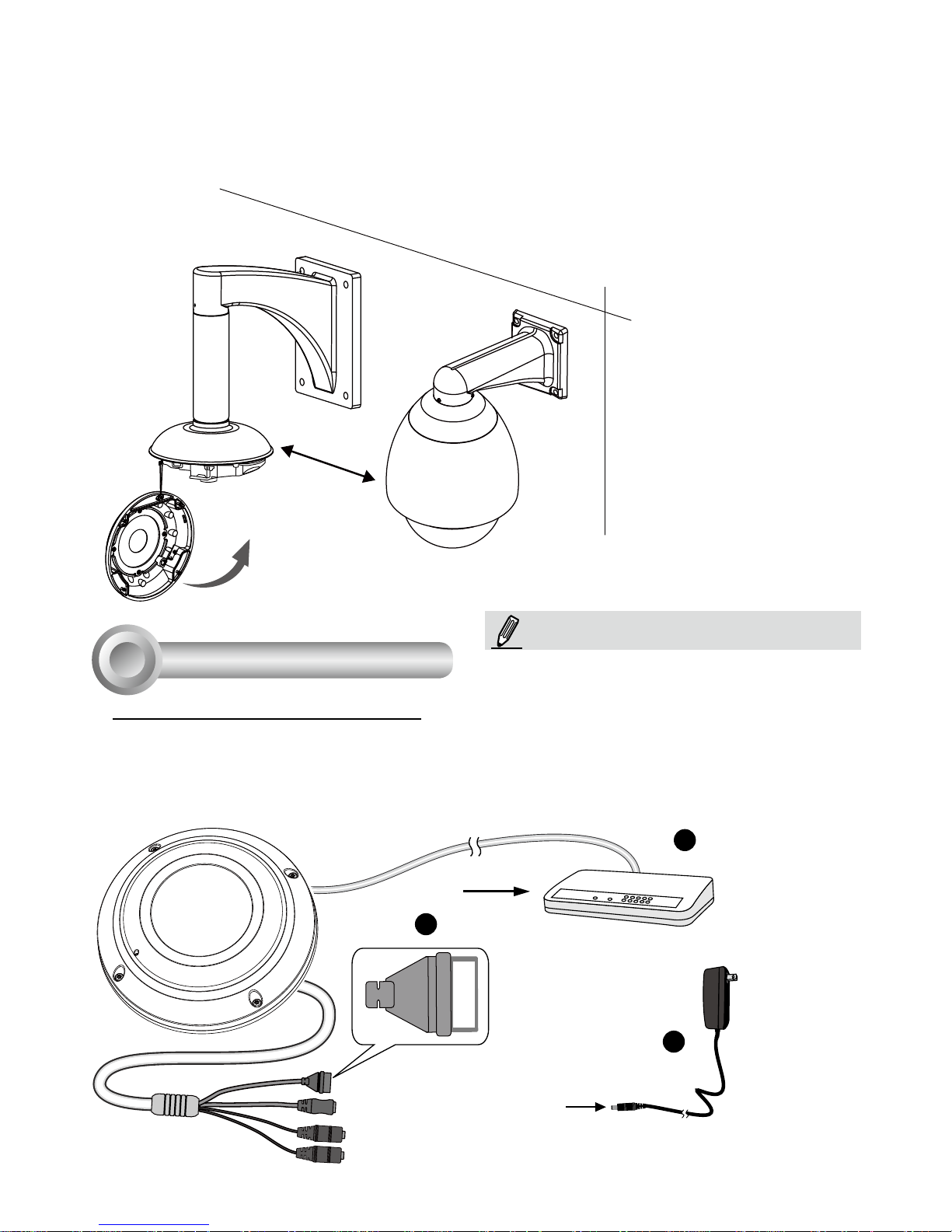
7. Install the speed dome camera next to the fisheye, with their lens positioned at approximately the
same height. For details about speed dome installation, please refer to its documentation.
8. Connect all cabling, including the IO cables to J6 and J7, and the Ethernet cable to RJ-45 connector.
9. Install the dome cover by fasteninng the anti-tamper screws.
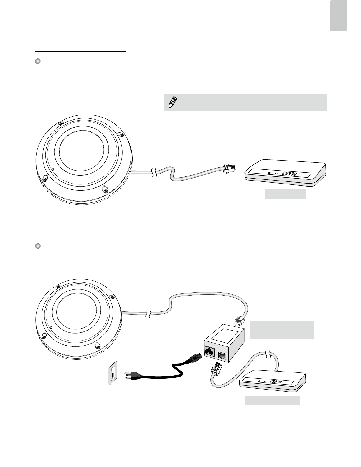
General Connection (without PoE)
1. Connect RJ45 Ethernet cable to a switch.
2. Connect the power cable from the Network Camera to a power outlet.
3. If you have external devices such as sensors and alarms, make the connection from the general
I/O terminal block.
4
POW
ER
C
O
LL
I
S
ION
L
I
N
K
RECEIVE
PARTITIO
N
1
2
3
4
5
+3V3
DO
D1
GND
1
2
3
General I/O Terminal Block
Power Cord Socket (Black)
Microphone In (Pink)
Audio Out (Green)
+3V3: Power, 3.3V DC
DO: Digital Output
D I: Digital Input
GND: Ground
NOTE:
If DC power is preferred, it should comply with: O/P:
12VDC, 1.5Amin., L.P.S. per IEC 60950-1.
Page 10
EN - 9
English
When using a non-PoE switch
Use a PoE power injector (optional) to connect between the Network Camera and a non-PoE
switch.
Power over Ethernet (PoE)
When using a PoE-enabled switch
The Network Camera is PoE-compliant, allowing transmission of power and data via a single
Ethernet cable. Follow the below illustration to connect the Network Camera to a PoE-enabled switch
via Ethernet cable.
POW
ER
C
O
LL
I
S
ION
L
I
N
K
RECEIVE
PARTITIO
N
1
2
3
4
5
PoE Switch
POW
ER
C
O
LL
I
S
ION
L
I
N
K
RECEIVE
PARTITIO
N
1
2
3
4
5
PoE Power Injector
(optional)
Non-PoE Switch
NOTE:
1. This equipment is only to be connected to PoE
networks without routing to outside plants.
2. For PoE input connection, use only UL listed I.T.E.
with PoE output.
Page 11
EN - 10
Ready to Use
Assigning an IP Address
1. Install “Installation Wizard 2” from the Software Utility directory on the software CD.
2. The program will conduct an analysis of your network environment. After your network is
analyzed, please click on the “Next” button to continue the program.
3. The program will search for VIVOTEK Video Receivers, Video Servers, and Network Cameras
on the same LAN.
4. After a brief search, the main installer window will pop up. Double-click on the MAC address
that matches the one printed on the camera label or the serial number on the package box label
to open a browser management session with the Network Camera.
5
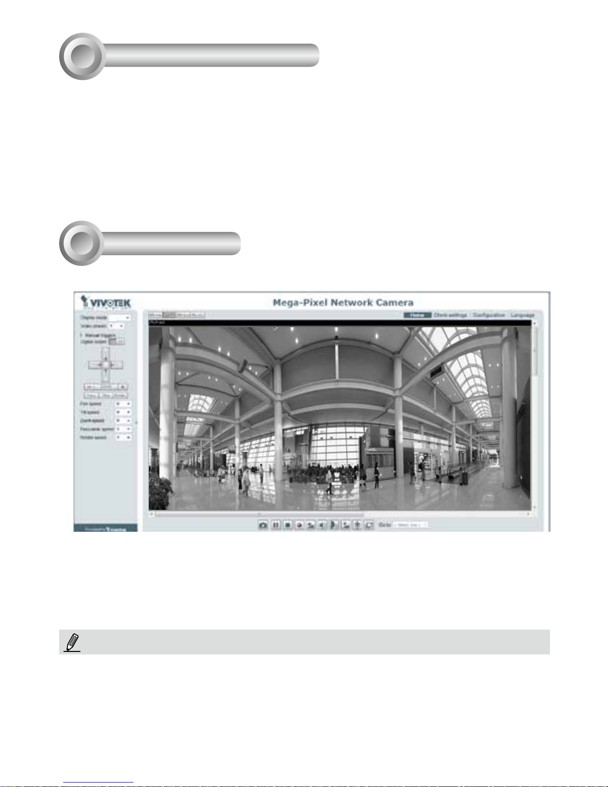
1. A browser session with the Network Camera should prompt as shown below.
6
1P
NOTE:
If you encounter problems with displaying live view or the onscreen plug-in control, you may try to
manually remove the plug-ins that might have been installed on your computer. Remove the following
folder: C:\Program Files (x86)\Camera Stream Controller.
2. Refer to the “Panoramic PTZ Installation Guide” in your product CD for the rest of the
configuration details.
Page 12
 Loading...