

Page 1

VIVOTEK
ND8301
Network Video Recorder
User’s Manual
VAST inside • HD Local Display •
Full Integration with VIVOTEK Cameras
Rev. 1.6.1.11
Rev. 1.6.1.11
Rev. 1.0
Rev. 1.2
Rev. 1.1b
User's Manual - 1
Page 2

VIVOTEK
Table of Contents
Revision History ..................................................................................................................................................... 8
Chapter One Hardware Installation and Initial Conguration .................................................................................... 10
Introducing ND8301 Network Video Recorder ..................................................................................................... 10
Special Features ........................................................................................................................................... 10
Physical Description ........................................................................................................................................... 11
Hardware Installation ............................................................................................................................................ 12
Network Deployment ............................................................................................................................................ 15
Initial Conguration ............................................................................................................................................... 16
Ready to Use ........................................................................................................................................................ 19
NVR Desktop Elements ........................................................................................................................................ 22
Control Center ............................................................................................................................................... 22
Menu Bar ....................................................................................................................................................... 23
Alarm Sound ................................................................................................................................................. 23
Chapter Two NVR LiveClient Conguration .............................................................................................................. 24
VAST LiveClient Functionality .............................................................................................................................. 25
VAST Server .............................................................................................................................................................. 26
Activating the VAST Server .................................................................................................................................. 26
How to Stop/Reboot the Server ............................................................................................................................ 26
LiveClient Conguration ............................................................................................................................................ 27
Opening the LiveClient Interface and Logging in ................................................................................................ 27
LiveClient User Interface ...................................................................................................................................... 28
Menu Bar ....................................................................................................................................................... 28
Status Panel .................................................................................................................................................. 28
Quick Access Bar ..........................................................................................................................................29
Live Video Monitoring Window ...................................................................................................................... 29
Hierarchical Management Tree .....................................................................................................................30
Camera Control Panel ................................................................................................................................... 31
Pan/Tilt/Zoom (PTZ) Control Panel ........................................................................................................ 31
Two Way Audio Control Panel ................................................................................................................ 32
Event Window ............................................................................................................................................... 33
Instant Playback (on remote LiveClient) ....................................................................................................... 34
Instant Replay (on remote LiveClient) ........................................................................................................... 34
Audio Control ................................................................................................................................................ 36
How to Manage Devices (Cameras) .................................................................................................................... 37
Insert Cameras .............................................................................................................................................. 37
Enable SVC .................................................................................................................................................. 41
Update Devices ............................................................................................................................................. 44
Delete Devices from the Station .................................................................................................................... 45
Batch Insert Cameras ................................................................................................................................... 46
Camera Conguration ................................................................................................................................... 50
View Live Videos ........................................................................................................................................... 53
2 - User's Manual
Dual / Multiple Streams .......................................................................................................................... 53
Page 3

VIVOTEK
Fisheye Display Modes .......................................................................................................................... 53
Refresh ................................................................................................................................................... 58
Streaming Server ................................................................................................................................... 58
Get Public IP ..........................................................................................................................................58
Camera Settings .................................................................................................................................... 59
Remove Live Video from the Video Monitoring Window ...............................................................................59
How to Change the VAST LiveClient Layout ........................................................................................................ 60
Changing the Layout of the Live Video Monitoring Window .......................................................................... 60
Switch Video Channels ..........................................................................................................................60
Congure Layout Mode .......................................................................................................................... 60
Rotating Video Pages ............................................................................................................................61
Edit Layout ............................................................................................................................................. 61
Maximize the Live Video Monitoring Window ................................................................................................ 63
How to Manage Stations ...................................................................................................................................... 65
Relay Settings ............................................................................................................................................... 65
How to Manage User Accounts ............................................................................................................................ 66
The Default User Roles and Permissions of User Accounts ......................................................................... 66
Manage a User Account ................................................................................................................................ 68
Add a New User Account .......................................................................................................................68
Permission of the User Account ....................................................................................................................69
Delete the User Account ...............................................................................................................................70
How to Set up Association Management .............................................................................................................. 71
Association Management .............................................................................................................................. 71
How to Set up Event Management ....................................................................................................................... 73
Event Management ....................................................................................................................................... 74
How to Congure the Station General Settings .................................................................................................... 81
Server Settings .............................................................................................................................................. 81
Log Settings .................................................................................................................................................. 81
Reboot Settings ............................................................................................................................................. 82
How to Congure Station Network Settings ......................................................................................................... 83
Port Settings .................................................................................................................................................. 83
UPnP Settings ............................................................................................................................................... 83
Proxy Settings ............................................................................................................................................... 83
Web Access Settings ..................................................................................................................................... 83
How to Edit Recording Stoage ............................................................................................................................. 84
Recording Storage Settings .......................................................................................................................... 84
Default Storage Group Settings ............................................................................................................. 85
Add New Storage Group(s) .................................................................................................................... 88
How to Edit Recording Schedules ........................................................................................................................ 89
Edit Schedule List ......................................................................................................................................... 90
Add Schedules ....................................................................................................................................... 90
Rename Schedules ................................................................................................................................ 90
Delete Schedules ................................................................................................................................... 90
Load/Save Schedule Templates .............................................................................................................91
Edit Camera List ............................................................................................................................................ 92
User's Manual - 3
Page 4

VIVOTEK
Edit Time Frame List ..................................................................................................................................... 93
Add New Time Frames ........................................................................................................................... 94
Recording Settings ................................................................................................................................. 95
The Concept of Repeat Frequency ............................................................................................................... 96
Repeat Frequency: Daily Setting ........................................................................................................... 97
Repeat Frequency: Weekly Setting (Day-based) ................................................................................. 100
Repeat Frequency: Monthly Setting (Day-based) ................................................................................ 103
Repeat Frequency: Yearly Setting (Day-based) ................................................................................... 105
How to Manually Begin /Stop Recording ............................................................................................................ 107
How to Edit Scheduled Backup Settings ............................................................................................................ 108
Select Backup Source ................................................................................................................................. 108
Setup Backup Schedule .............................................................................................................................. 109
Select Backup Target .................................................................................................................................. 109
Other Options .............................................................................................................................................. 109
How to Congure Station Server Settings ...........................................................................................................110
DDNS Settings .............................................................................................................................................110
Network Storage Server Settings .................................................................................................................111
SMTP Settings .............................................................................................................................................112
How to Use the Talk Panel ..................................................................................................................................113
Add a Camera to the Talk Panel ...................................................................................................................113
Remove a Camera from the Talk Panel .......................................................................................................115
How to Congure E-map Settings .......................................................................................................................116
Upload an E-map .........................................................................................................................................116
E-map Settings Page (View Mode) ..............................................................................................................117
Quick Access Bar ..................................................................................................................................118
Status Panel ..........................................................................................................................................118
E-map Settings Page (Edit Mode) ................................................................................................................119
Device Management ................................................................................................................................... 120
Live View Dialog Settings ............................................................................................................................ 121
Open Live View Dialog ......................................................................................................................... 121
Send to Single View ............................................................................................................................. 121
E-map Link .................................................................................................................................................. 122
How to Congure Client Settings ....................................................................................................................... 125
Snapshot Settings ....................................................................................................................................... 125
Taking a Snapshot................................................................................................................................ 126
Recording Settings ...................................................................................................................................... 127
Type 1: Record to EXE ........................................................................................................................ 127
Type 2: Record to 3GP ......................................................................................................................... 127
Type 3: Record to AVI .......................................................................................................................... 128
Built-in Media Player--EXE ................................................................................................................... 131
View Settings ............................................................................................................................................... 133
Display Location ................................................................................................................................... 133
Date and Time Format ......................................................................................................................... 134
Video Display Mode ............................................................................................................................. 134
Font Settings ........................................................................................................................................ 134
General Settings ......................................................................................................................................... 135
4 - User's Manual
Page 5

VIVOTEK
System Settings ................................................................................................................................... 135
Event Settings ...................................................................................................................................... 136
Rotation Settings .................................................................................................................................. 136
Display Settings ................................................................................................................................... 137
Joystick Settings ......................................................................................................................................... 139
Enable Joystick .................................................................................................................................... 139
Proxy Settings ............................................................................................................................................. 143
How to Use PiP (Picture-in-Picture) ................................................................................................................... 144
Enable PiP ................................................................................................................................................... 144
Global View .......................................................................................................................................... 144
ROI (Region of Interest) ....................................................................................................................... 145
Digital Zoom In ..................................................................................................................................... 145
Snapshot Zoomed In Image ................................................................................................................. 145
PiP Settings .......................................................................................................................................... 145
How to Congure Video Enhancement .............................................................................................................. 146
Basic Image Adjustment .............................................................................................................................. 146
Defog ........................................................................................................................................................... 148
Apply a Preset Defog Prole ................................................................................................................ 148
Create a New Defog Prole ................................................................................................................. 149
How to Search for a Device on the Hierarchical Device Tree ............................................................................ 151
How to Lock LiveClient for Security Concerns ................................................................................................... 152
How to Log out from the VAST Server ............................................................................................................... 152
How to Exit VAST LiveClient .............................................................................................................................. 152
Lauch Playback ................................................................................................................................................. 153
Second View ...................................................................................................................................................... 153
Chapter Three NVR Playback Conguration ........................................................................................................... 154
Activating VAST Playback and Logging in to a Server ....................................................................................... 154
VAST Playback User Interface ........................................................................................................................... 156
Menu Bar ..................................................................................................................................................... 156
Status Panel ................................................................................................................................................ 156
Quick Access Bar ........................................................................................................................................ 157
Recorded Video Playback Window ............................................................................................................. 157
Query Panel-- Browsing Page ..................................................................................................................... 158
Query Panel--Time Search Page ................................................................................................................ 159
Query Panel--Event Search Page ............................................................................................................... 160
Query Panel--Bookmark Search Page ........................................................................................................ 161
Query Panel--Log Viewer Page ................................................................................................................... 162
Video Clips List Window .............................................................................................................................. 163
Playback Control Panel ............................................................................................................................... 164
How to Playback Recorded Video ...................................................................................................................... 165
Select a Recorded Video Clip ..................................................................................................................... 165
Remove Recorded Video Clips from Video Cells ........................................................................................ 167
Timeline Slider Bar and Histogram .............................................................................................................. 167
Zoom in / out of the Histogram .................................................................................................................... 168
Audio Control .............................................................................................................................................. 169
How to Change the Playback Layout ................................................................................................................. 170
User's Manual - 5
Page 6

VIVOTEK
Changing the Layout of the Recorded Video Playback Window ................................................................. 170
Switch Video Channels ........................................................................................................................ 170
Layout Mode ........................................................................................................................................ 170
Maximize the Recorded Video Playback Window ....................................................................................... 171
How to Backup Recorded Video ........................................................................................................................ 173
How to Search for a Video Clip Taken at a Specic Time .................................................................................. 179
How to Add a Bookmark ..................................................................................................................................... 180
How to Search for Events ................................................................................................................................... 181
Select Event Category ................................................................................................................................ 182
Event Category- All Events .................................................................................................................. 182
Event Category- All Motion Events....................................................................................................... 182
Event Category- All IVA events ............................................................................................................ 183
Event Category- All DI Events .............................................................................................................. 183
Event Category- Named DI Events ...................................................................................................... 184
Start Event Search ...................................................................................................................................... 185
Backup the Event Videos ............................................................................................................................ 186
How to Search for a Bookmark .......................................................................................................................... 187
How to Search Logs ........................................................................................................................................... 188
Select Log Category/Log Type/Log Level ................................................................................................... 189
Search All Local Logs........................................................................................................................... 190
Search Login History ............................................................................................................................ 190
Search Login Activities ......................................................................................................................... 191
How to Congure Client Settings ....................................................................................................................... 193
Snapshot Settings ....................................................................................................................................... 193
Export Settings ............................................................................................................................................ 193
View Settings ............................................................................................................................................... 195
Proxy Settings ............................................................................................................................................. 195
General Settings ......................................................................................................................................... 195
System Settings ................................................................................................................................... 195
Display Settings ................................................................................................................................... 195
How to Congure Video Enhancement .............................................................................................................. 195
How to Search for a Device on the Hierarchical Management Tree .................................................................. 195
How to Lock VAST Playback for Security Concerns .......................................................................................... 196
How to Log out from the VAST Server ............................................................................................................... 196
How to Exit VAST Playback ................................................................................................................................ 196
Chapter Four Auxiliary Utilities ................................................................................................................................ 197
Service ............................................................................................................................................................... 198
Import and Export Utility ..................................................................................................................................... 198
Installation Wizard 2 .......................................................................................................................................... 200
Shepherd ............................................................................................................................................................ 201
Upgrade ............................................................................................................................................................. 203
File Manager ...................................................................................................................................................... 204
Keyboard ............................................................................................................................................................ 204
Disk Status ......................................................................................................................................................... 205
Network Status ................................................................................................................................................... 206
System Status .................................................................................................................................................... 207
6 - User's Manual
Page 7

VIVOTEK
Appendix A Rebuilding a RAID Volume ................................................................................................................... 208
Appendix B ONVIF Support..................................................................................................................................... 210
User's Manual - 7
Page 8

VIVOTEK
Revision History
Rev. 1.0: Initial release.
Rev. 1.1:
• Corrected description of the functions on e-map's right-click menu.
• Added short description for the Auto stream size feature.
• Added the Bookmark function.
• Added description for the Instant Replay function (on a remote client).
Rev. 1.2:
• Added Appendix B ONVIF Support.
• Added the description for CPU and memory usage indicators.
Read Before Use
The use of surveillance devices may be prohibited by law in your country. The Network Camera
is not only a high-performance web-ready camera but can also be part of a exible surveillance
system. It is the user’s responsibility to ensure that the operation of such devices is legal before
installing this unit for its intended use.
It is important to first verify that all contents received are complete according to the Package
Contents listed below. Take note of the warnings in the Quick Installation Guide before the
Network Camera is installed; then carefully read and follow the instructions in the Installation
chapter to avoid damage due to faulty assembly and installation. This also ensures the product is
used properly as intended.
The Network Camera is a network device and its use should be straightforward for those who
have basic networking knowledge. It is designed for various applications including video sharing,
general security/surveillance, etc. The Configuration chapter suggests ways to best utilize the
Network Camera and ensure proper operations. For creative and professional developers, the
URL Commands of the Network Camera section serves as a helpful reference to customizing
existing homepages or integrating with the current web server.
Package Contents
■ ND8301
■ Power cord and power adapter
■ Software CD
■ Warranty Card
■ Quick Installation Guide
8 - User's Manual
Page 9

VIVOTEK
i
NOTE:
The operating system and VAST server are installed on an IDE ash mounted on the main board. There
is no need to install software.
Symbols and Statements in this Document
INFORMATION: provides important messages or advices that might help prevent inconvenient
or problem situations.
NOTE: Notices provide guidance or advices that are related to the functional integrity of the
machine.
Tips: Tips are useful information that helps enhance or facilitae an installation, function, or
process.
WARNING! or IMPORTANT: These statements indicate situations that can be dangerous or
hazardous to the machine or you.
Electrical Hazard: This statement appears when high voltage electrical hazards might occur
to an operator.
User's Manual - 9
Page 10

VIVOTEK
Chapter One Hardware Installation and
Initial Configuration
Introducing ND8301 Network Video Recorder
VIVOTEK ND8301 is an 8 CH Network Video Recorder designed for sophisticated recording applications. The unit is equipped with an Intel Dual-core Atom Processor with maximum recording
throughput at a robust 96 Mbps. RAID 0/1 is supported with two removable HDDs for backup
efficiency, with an external eSATA port for additional expansion. A first for the VIVOTEK NVR series, a local display output port is now available with full HD resolution (1920X1080), eliminating
the need for a separate PC to view video from the unit. Setup of parameters such as IP, HDD,
and basic camera configuration can easily be performed with the setup wizard, making the
ND8301 the easiest NVR to use yet. When using more than one of the same model of VIVOTEK camera, the “Shepherd” program can be used to duplicate configuration settings to multiple
cameras.
The ND8301 operating system is the VIVOTEK professional central management software
VAST, allowing for simple and effective management of a surveillance system using the Liveclient and Playback functions. As VIVOTEK camera features are fully integrated into VAST,
cutting-edge edge technologies such as SVC and Activity Adaptive Recording can be utilized to
conserve bandwidth and optimize recording. A server running VAST software can also directly
control ND8301, and compatibility with the iViewer application allows for access to the ND8301
on mobile devices. By integrating all of the components together using the VIVOTEK ND8301/
Cameras/VAST/iViewer, users can realize a fully featured and robust next-generation surveillance system.
Special Features
Intelligent PiP Function -- Digital Zoom In Mode
Convenient Remote Access via Client/Server Architecture
Effective & Reliable Event Trigger Management
Real-time 16-channel Live Viewing and single channel (VGA) Playback
Multiple Simultaneous Streams for Different Media Platforms
Activity Adaptive Streaming for Dramatically Reducing Bandwidth and Storage Space
Extremely Versatile Settings for Recording Storage and Recording Schedule Management
Role-based User Management to Enhance Security Operations
Efficient Data Backup, Search, and Export
Intelligent PTZ/ E-PTZ Remote Camera Control
Overall Device Management through Intuitive E-map Feature
Supports Two Way Audio
Supports Auto Stream Size
Supports SVC adaptive frame rate setting
* The number of linked devices will depend on the license purchased along with the system.
* The ability to extend devices is also subject to the network bandwidth and computer performance.
10 - User's Manual
Page 11

Physical Description
Front View
Disk 1
Disk 2
Rear View
VIVOTEK
HDD LED
Power
button & LED
Reset button
RS-232 (reserved) LAN
WAN
USB2
VGA
combo
USB1
combo
eSATA
MIC-In
IMPORTANT:
It is important to leave a clearance of 15cm
to the rear side of the chassis. The clearance
is required to ensure an adequate airow
through the chassis to ventilate heat. A 5cm
clearance is also required on both sides of
the chassis.
Line In
Line Out
DC Power
Fan exhaust
outlet
15cm
To ensure normal operation, maintain ambient airow. Do not block the airow around
chassis such as placing the system in a
closed cabinet.
5cm
5cm
5cm
User's Manual - 11
Page 12

VIVOTEK
IMPORTANT:
For a RAID volume conguration, it is recommended you use hard drives of the same model
featuring the same capacity and rotation speed, even running the same version of rmware.
Hardware Installation
SATA hard disk(s) are user-supplied. The network video recorder can readily accommodate
most of the off-the-shelf SATA hard drives.
1. Use a at-blade screwdriver to unlock the rotary bezel lock. Open the drive bay bezel by pulling the lever on it.
Bezel Lock
Bezel Lever
2. Install your hard disk to the drive bay. Gently put the hard disk into drive bay with its label
side facing up and the connector side towards the inside of the chassis. Push the hard disk
in. Stop pushing it when you feel the contact resistance.
12 - User's Manual
Page 13

3. Close the drive bay bezel.
HDD
VIVOTEK
Bezel Lever
4. 4-1. Press on the left edge of the drive bay bezel to snap it into place.
4-2. Use a at-blade screwdriver to turn the bezel lock to the “locked” position.
You should always lock the drive bezel when the drive bay is populated. This ensures the
hard drive is securely installed.
Bezel Lock
2
1
User's Manual - 13
Page 14

VIVOTEK
Interface Connections
1 & 2. Connect CAT5 or better-quality Ethernet cables to cameras via a local, switched network,
or clients through the Internet. Refer to next page for more information.
3. Connect the DB15 VGA port to a monitor (with resolutions up to 1920x1080).
4. Connect USB devices such as keyboard and mouse.
5. If an external eSATA storage enclosure is available, connect it to the eSATA port.
6. Connect speakers or microphone to the phone-jack connectors.
7. Connect the supplied 100-240V DC power adaptor. (50~60Hz, 5A)
LAN WAN
Router
LAN
1 2
3 4 5
Internet
6
7
VGA
14 - User's Manual
Audio devices
DC power adaptor
USB devices
External enclosure
Page 15

VIVOTEK
Network Deployment
1. Connect the supplied power adapter to a power outlet.
2.
Connect network cameras to the NVR’s LAN ports.
3. If you want to access NVR over the Internet, connect the NVR to the Internet via the WAN
port. A web console can be established from a remote PC by keying http://<public IP>:3454 in
a browser’s URL address eld. However, port forwarding on the router for the TCP port will be
necessary.
4. Push the power button to run the NVR.
Clients
Router
Internet
Switch
Wireless AP / Router
Default Fixed IP:
192.168.1.10
Default: DHCP
LAN WAN
NOTE:
The LAN and WAN ports can be congured into the same or different subnets.
Router
You may also connect cameras through the WAN port. If you have cameras connected via the
WAN port, make sure the WAN port and the cameras connected through it acquire static IP
addresses even when the WAN port is connected to router or AP. If not, the cameras detected
through the WAN port will use the default IPs, e.g., 169.254.xx.xx, and the LiveClient software
will not be able to detect their presence.
User's Manual - 15
Page 16

VIVOTEK
Initial Conguration
1. The system power on self test and OS initialization takes about 2 minutes to complete. Once
your NVR is started, you will be prompted by the Setup Wizard. You should then begin the
initial setup. The system is booted from an embedded IDE ash. No software installation is
required.
NOTE:
1. NVR System
During boot-up, a Startup Menu will prompt allowing you to restore system to factory defaults.
This function is only required in circumstances that you need to renew all system settings, such
as moving the NVR to a different installation site or network environment.
2. Enter the default User name and Password as admin & admin. It is recommended you
change the password later to prevent unauthorized access.
3. Click Next to proceed with conguration and follow the onscreen instructions to nish the
conguration process.
4. Note the following when you move to the Network page:
4-1. If your local network has a DHCP server, you can select the "Get IP address
automatically (DHCP)."
4-2. If your LAN port connects to an isolated switch with cameras attached to it, you can
manually assign IP addresses to cameras, and the address for the LAN port itself.
The default static IP for the LAN port is 192.168.1.10.
16 - User's Manual
Page 17

VIVOTEK
4-3. Connect your WAN port to a router or AP with the routing capability and then to a DSL or
Cable modem.
User's Manual - 17
Page 18

VIVOTEK
5. On the Disk page, Select disk drives by clicking the checkboxes in front of disk drives.Select
Build single disk, Build RAID0, RAID1, or other option from the Disk conguration pull-
down menu. Click Apply and wait for a few minutes for the conguration to take effect.
Refer to the description available with every disk volume type on the screen, such as those
for RAID0 and RAID1.
6. On the Camera page, all cameras connected through the local network should appear on
a Camera list after a brief search. You can manually assign IP addresses by clicking on
the cameras' address eld. You can also select the "Assign IP addresses to all cameras"
checkbox and let NVR assign IPs to cameras.
Click Next to end the initial setup. Make sure you have the cameras' access credentials in
order to make individual changes. It is also highly recommended to synchronize cameras'
time with that of the NVR system. Click the checkbox below for an automated synchronization.
18 - User's Manual
Page 19

VIVOTEK
Ready to Use
1. You will then be at the Control Center screen. Double-click on the LiveClient or Playback
buttons to congure live viewing and recording settings.
2. Open the LiveClient utility to change live view layout, camera streaming frame rate, and other
options.
3. 3-1. By default, the Batch Insert Cameras window will prompt for you to recruit cameras into
your conguration.
You may also access the same conguration page in the Conguration menu. Select
Camera Management > Batch Insert Cameras.
User's Manual - 19
Page 20

VIVOTEK
3-2. Click on the Search button.
3-3. Select cameras by clicking their checkboxes.
3-4. Click OK, return to the previous window, and click the Insert button.
20 - User's Manual
Page 21

VIVOTEK
4. It is important to ensure that the live viewing and recording conguration does not
exceed the system's limits:
In terms of local display, the default stream 1 for live view can be congured with a
resolution up to Full HD 30fps. Stream 1 is also a source for continuous recording.
Make
sure your cameras' stream 1 resolution does not exceed 1080P at 30fps.
Compression MJPEG H.264
Resolution 1080P 720P VGA CIF 1080P 720P VGA CIF
Frame rate 15fps 30fps
by bit rate /
video quality
No. of streams - - 9 16 1 1 3 7
Compression MPEG-4
Resolution 1080P 720P VGA CIF
Frame rate 30fps
by bit rate /
video quality
No. of streams 2 2 5 16
6Mbps 6Mbps 1Mbps 512kbps
Good 6Mbps 6Mbps 1Mbps 512kbps
The NVR supports Auto Stream Size, which automatically adjusts streaming display for
efcient leverage of system resources. If you disable the Auto Stream Size function and
manually congure your stream settings, you must comply with the limitations listed above.
IMPORTANT:
You may need to congure a recording stream of a particular resolution and bit rate. When doing
this, you should make sure the Recording load does not exceed the maximum 96Mbps as the
sum of bit rates per second allocated for all recording streams. If you have multiple cameras and
the upper bound is exceeded, proceed with the following:
Congure the Recording setting in Conguration > Camera Management > Update
Camera. When the Update window prompts, select a camera. Click on the Recording
Settings tabbed menu, and select a smaller stream (in higher or lower bit rate or resolution)
as the source of recording. Click Update to save your conguration and repeat the setting
until the recording load is back within the 96Mbps limitation.
User's Manual - 21
Page 22

VIVOTEK
NVR Desktop Elements
Control Center
Menu Bar
Desktop Shortcuts
Normally the desktop defaults to the Control Center view, which provides direct access to
various functional utilities such as LiveClient and Playback. The functions of these utilities are
summarized as follows:
Utility Description
Setup Wizard The Setup Wizard guides your through important steps on initial setup. Most of
the storage-related settings are managed through this wizard, such as creating
disk volumes, formatting, and breaking down existing disk volumes.
LiveClient LiveClient and Playback are the most important interfaces to the NVR's
various functionalities. LiveClient provides a centralized management interface
to the NVR system, provides live viewing, PTZ / E-PTZ operation, PiP, E-Map,
etc. Refer to Chapter Two on page 24 for the operation details.
Playback Playback enables access to recorded videos, snapshot, bookmark, backup,
and retrieval of recorded video, and more. Refer to Chapter Three on page
154 for the operation details.
Service Services enables you to restart or stop the embedded NVR server (VAST
server).
Import/ Export The Import/ Export utility helps preserve current system conguration or reload
a previously-saved conguration.
Installation
Wizard 2
The IW2 utility offers a glimpse of VIVOTEK cameras and the access to them
in a local area network.
Shepherd You can use Shepherd to quickly duplicate individual camera conguration
(system, video streams, network, security, etc.) to multiple cameras. Please
refer to page 203 for more about this utility.
Except for LiveClient and Playback, detailed description of the auxiliary functions can be found
in Chapter Four on page 199.
22 - User's Manual
Page 23

VIVOTEK
Upgrade The Upgrade provides access to NVR system updates.
File Manager The File Manager helps locate particular system or video data when the need
arises, say, for retrieving forensic evidences.
Keyboard If a keyboard is not available, use this virtual keyboard for entering data.
Power down
button
Use it to power down or restart the system.
NOTE:
The system should always be powered off using the Power Down button on the desktop. If the
system should hang for some reasons, you can press the power button on the front panel for 4
seconds to power off the system.
Menu Bar
The menu bar contains the following menus:
Menu Description
Control Center As previously described, the Control Center is the main access point to major
functionalities.
Disk Status Disk Status provides a glimpse of Logical Volumes, Physical disk statuses, HDD status
reported through S.M.A.R.T. (Self-Monitoring, Analysis and Reporting Technology), and
a test tool to check the integrity of individual disk drives.
Network Status Displays the network statuses of the NVR's two GbE Ethernet ports, including network
type, IP address, subnet, and gateway information.
System Status Reports system overall working status.
Most of the NVR's major functionalities are managed through the LiveClient and Playback
interfaces, refer to Chapter 4 for descirption of auxiliary functions.
The operating system and VAST server are installed on an IDE ash mounted on the main
board. There is no need to install software.
Except for LiveClient and Playback, detailed description of the auxiliary functions can be found
in Chapter Four started from page 199.
Alarm Sound
The onboard buzzer will sound if the following occurs: A hard drive is
removed or if the LAN or WAN port is disconnected. Mute the alarm by
closing the event prompt.
The hard disk reported as "failed" via S.M.A.R.T. will also trigger the
alarm sound and a warning message.
User's Manual - 23
Page 24

VIVOTEK
i
Chapter Two NVR LiveClient Configuration
Centralized management site for all the logged in clients
An NVR can also be managed using a separately-installed LiveClient on a remote PC (rev.
1.7.x or later).
Local 1080P HD display
Up to 16 video recording channels
Store recorded data onto a total of four hard disks (single disks, RAID0, or RAID1 configura-
tions)
Live video for the local/remote LiveClient users
Retrieval of recorded video for the local/remote Playback users
LiveClient is the management interface to your NVR server. The server-related settings
are made via the VAST LiveClient utility. The convenient and intuitive user interface on the
LiveClient helps managing cameras, live monitoring, and recording congurations.
Information:
• Only users with the Administrator's privileges can manage the LiveClient/s various function
groups.
• The maximum length of recording will depend on the video recording settings, the number of
cameras, and Storage Group settings.
Below are the approximate numbers for a recording task. A Constant Bit Rate method (xed
bit rate per second) is recommended to control the bandwidth and total le size consumed
with continuous recording.
If the max. bit rate for each camera is set to 6Mbps at the 1080P resolution (in H.264), each
recording channel requires 6Mb x 86400 / 8 = 63.3GB each day as storage space. With 8
recording channels, a 759GB of storage space is required for continuous recording for one
day.
A RAID0 volume consisting of 2x 2TB disk drives can hold the 8 HD streaming recording for
5 days.
24 - User's Manual
Page 25

VIVOTEK
VAST LiveClient Functionality
Server function control
User account management
Recording storage management
Recording schedule management
Recorded data backup and automated schedule
Event trigger management
Flexible video live view layout
A screen for a maximum of 8 channels for simultaneous monitoring
1x1, 2x2, 3x3, 4x4, 1+5, and 1+12 monitoring layouts
Multiple video viewing pages
Intelligent PiP (Picture in Picture) function
E-map for overall management
Networked storage for recorded video
PTZ / E-PTZ operation panel for camera control
Supports two way audio
Supports joystick control
Remote configuration for network cameras
Instant Replay of video taken seconds earlier (on a remote LiveClient console due to limita-
tions on system sources)
User's Manual - 25
Page 26

VIVOTEK
VAST Server
Activating the VAST Server
VAST Server is a service program that will run automatically when your NVR system starts.
The VAST server manages video recording, live view monitoring, and other related surveillance
functions.
How to Stop/Reboot the Server
Please follow the steps below to stop/reboot the server:
1. Click on the VAST Service shortcut on the Control Center desktop.
2. There are 3 options: Start Service, Stop Service, and Restart Service. It’s selectable using the buttons
below. Stop Service can be used to promptly stop a recording task or access from a remote computer.
26 - User's Manual
Page 27

VIVOTEK
LiveClient Configuration
Opening the LiveClient Interface and Logging in
VAST LiveClient allows you to monitor live video from cameras managed by the NVR; it is also
the main access to the server's functional control.
Double-click on the LiveClient shortcut on the desktop to open the LiveClient utility:
1. The login box will prompt. Provide the default User Name and password as admin and admin.
2. Click on the Login button to continue.
3. The VAST LiveClient monitoring window will prompt.
NOTE:
Available functions of the LiveClient program will be enabled according to the privileges granted for your
login account. For more details about user account, please refer to How to Manage User Accounts on
page 57.
User's Manual - 27
Page 28

VIVOTEK
F
LiveClient User Interface
E
A
B
C
D
G
A. Menu bar B. Quick access bar C. Hierarchical management tree
D. Camera control panel (PTZ / Two way audio / Instant Playback control panel)
E. Live view window F. Status panel G. Event window
Menu Bar
Menu Item Drop-down Options
System
Edit
View PTZ Panel / Two Way Audio Panel / Event Window / Full Screen / Minimize
Conguration
Layout Start Rotating (Stop Rotating) / Save to / Delete / Choose / Patrol
Help About
Lock / Enable Click On Image (Disable Click On Image) / E-map / Launch Playback / Logout /
Exit
Manually Begin Recording (Stop Manual Recording) / Snapshot / Record to EXE / Snapshot
Zoomed Image / Find
Camera Management (Insert Camera / Update Camera / Delete Cameras / Batch Insert
Cameras / Camera Configuration) / User Management / Association Management / Event
Management / Station Settings (General Settings / Network Settings / Recording Storage
Settings / Recording Schedule Settings / Scheduled Backup Settings / Server Settings / Relay
Settings) / Client Settings (Snapshot Settings / Recording Settings / View Settings / General
Settings / Joystick Settings / PiP Settings) / Video Enhancement (Basic Image Adjustment /
Defog)
Status Panel
28 - User's Manual
User Name CPU
Station Name (IP Address) usage
Login Time (yyyy-mm-dd hh:mm:ss) RAM
Current Time (yyyy-mm-dd hh:mm:ss) usage
Page 29

Quick Access Bar
Icon Function Description
Exit Exit the system
Logout Log out from the current station
VIVOTEK
Lock Click to Lock the system for security concerns (
Volume Adjust the audio volume of the current video ( Mute)
Snapshot Capture pictures from the focus live video cell
Record to Media Record media in EXE/3GP/AVI format (
Alert Sound Silence a triggered alarm when an event occurs, e.g., a DI is triggered.
Adjust SVC Level Dynamically adjust the SVC control over frame rates
Remove All Connections Remove all live videos from the live view window
Layout Change the layout of the live view window
Full Screen Maximize the live video cell
Page Up Switch to the previous live view page
Page Down Switch to the next live view page
Start / Stop Rotating Start or stop live view layout rotating
Recording Media)
Unlock the system)
NOTE:
Some buttons will be disabled if the selected devices do not support the related functions.
Live Video Monitoring Window
The "VIVOTEK" logo is displayed where no camera has been assigned to a video cell.
The red frame ( ) represents the current selection.
Video Cell
User's Manual - 29
Page 30

VIVOTEK
Hierarchical Management Tree
Station Name (IP address)
Connected devices listed under the station
Camera name (IP Address)
Connected devices that have been assigned
to the default recording storage
Layout list
Icon Description
A station (The NVR running the VAST Server)
/
/
/
/
/
/
/
VIVOTEK xed network camera
Red dot signies that the camera is recording.
VIVOTEK PTZ network camera
Red dot signies that the camera is recording.
VIVOTEK dome network camera
Red dot signies that the camera is recording.
VIVOTEK sheye network camera
Red dot indicates that the camera is recording.
VIVOTEK video server
Red dot signies that the video server is recording.
Digital input on / off
Digital output on / off
A layout of the live monitoring window
A station that’s not able to be connected currently.
A device that’s not able to be connected currently.
NOTE:
A Logical Tree will be available with the LiveClient console separately installed on a remote PC. The Live Client
instance will be available in the Software CD that comes with the NVR system (rev. 1.7.x). That particular edition
allows the NVR and cameras under it to be listed with other VAST server congurations.
30 - User's Manual
Page 31
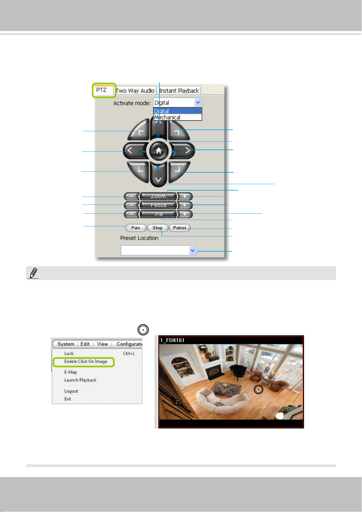
Camera Control Panel
Pan/Tilt/Zoom (PTZ) Control Panel
VIVOTEK
Up
op left
T
Top right
Return to home position
Left
Bottom left
Right
Bottom right
Down
Auto focus
Zoom out
Focus near
Close
Zoom in
Focus far
Open
Auto iris
Start to auto pan
Start to auto patrol
Stop auto panning/patrolling
Drop-down list of preset positions
NOTE:
There are two types of PTZ control: Digital (E-PTZ for megapixel cameras) and Mechanical (PTZ cameras or
fixed cameras with camera control via RS-485). If the connected cameras support PTZ/E-PTZ function, the
PTZ option(s) will appear on the drop-down list. For detailed camera control settings, please refer to the user's
manual of VIVOTEK network camera .
Click System > Enable Click On Image to use the mouse for the control of the PTZ and e-PTZ functions in the
video cells for linked cameras. An icon
will appear in the video cell as shown below.
2012/12/10 17:08:56
You can control the PTZ function through a joystick as well. For more information regarding to the joystick
conguration, please refer to instructions on page 139.
User's Manual - 31
Page 32

VIVOTEK
Two Way Audio Control Panel
The two way audio function allows the user to remotely communicate with people nearby the
network camera.
Selected device that
can use the two way
audio function
Click to play sound from the camera
Click to talk
Select sound from the
le list
Click to play the selected
sound on the client's side
Click to adjust volume
NOTE:
For detailed information about How to Use the Talk Panel, please refer to page 113.
Only cameras that come with the two way audio function can be added to the Talk Panel.
The Language selection menu has been moved to the Setup Wizard.
Remove all cameras
from the Talk Panel
32 - User's Manual
Page 33

VIVOTEK
Event Window
Click View > Event Window to insert a window showing the real-time information for event
triggers. If you want to hide this window, deselect this option on the menu bar.
Event Window
The default event window is xed on the bottom of the
LiveClient. If you want to change the event window as
a popup page, please click Configuration > Client
Settings > General Settings to switch the modes.
The Type eld in the event window shows the event category and another eld Description displays
the percentage of motion in the detection window. You can open an individual web console with the
camera (left-click to select, right-click to oepn Camera Setting) to congure Motion Detection and set
the percentage.
Video(TCP-AV)
NOTE:
For more information about DI/DO settings, please refer to Association Management on page 71.
User's Manual - 33
Page 34

VIVOTEK
Instant Playback (on remote LiveClient)
Instant Playback is available on a remote LiveClient console. Check View > Instant Playback to
open the window on the panel. The entries are the short recordings made from triggered events.
Uncheck this item if you want to hide this window.
Instant Playback Window with a slide bar, play, pause, and stop function
The recorded media that was triggered by an event will be indicated by an
icon.
You can double-click an event on the list to playback the recorded video. Each event contains a
video clip of about 20-seconds in length. (The default recording data of an event is 20 seconds.
For more information about event recording, please refer to page 87.)
Instant Replay (on remote LiveClient)
If a camera is currently recording to the NVR, then a Replay button will be available at the
lower left corner of its view cell. This allows you to immediately retrieve the video recording in
the past 30 seconds.
The Instant Replay function enables you to quickly retrieve videos of what has just happened (20
seconds to 15 minutes ago), without the need to open the Playback utility for the past videos.
NOTE:
The Switch Monitor button is available on an independent LiveClient instance installed on a remote PC. For a
direct connection with the NVR, this button is not available.
34 - User's Manual
Page 35

VIVOTEK
Prerequisites for Instant Replay:
1. The function is enabled by default, only available on a LiveClient installed on a PC.
2. There must be recorded videos of the immediate past. If the video streams from a camera
were not recorded, you can not retrieve videos using the Instant Replay function.
NOTE:
1. When using the Instant Replay function and you change the stream number on a video cell,
the Instant Replay will be interrupted.
2. The Instant Replay will also be interrupted when the time comes for a rotation of Live View
pages. For example, if you have multiple Live View pages and you set up a rotation of these
pages by every 10 seconds, page swap (rotation) still has a higher priority even if you are
viewing the Instant Replay.
How to Use:
1. On a selected view cell, mouse over to the lower left corner. A Replay icon
will appear.
2. Click on it to display the Replay control bar. Click on the play button.
3. The default queue length is 30 seconds. You can click on the number on the right to change
the queue length.
The queue length configuration stays with the
view cell, and it will not go unless you remove
and insert the camera again.
4. To stop the Replay and return to the Live View, click on the Return to Live button.
5. On a Replay view cell, you can apply the same Snapshot, Print, Single view and Full screen
control as those on a normal view cell. You can also right-click to display the Display Mode
and Video Enhancement functions.
Click and drag the playhead to skip or move to a different point in time on the playback.
An active Replay view cell is indicated by the Replay text indicator and the time of occurrence
of the current playback.
User's Manual - 35
Page 36

VIVOTEK
To change the default Replay settings, open the Conguration > Client Settings > General
Settings menu.
Audio Control
The audio function will be enabled if the device is equipped with an internal or external
microphone. For detailed audio control settings, please refer to page 138.
36 - User's Manual
Page 37

VIVOTEK
How to Manage Devices (Cameras)
Please follow the steps below to open the Camera Management window:
a. Select the station from the hierarchical management tree.
b. Click Conguration > Camera Management on the menu bar (or right-click the station, then select
Camera Management).
c. Then you can choose to insert, update, delete, or batch insert cameras.
b
a
a
b
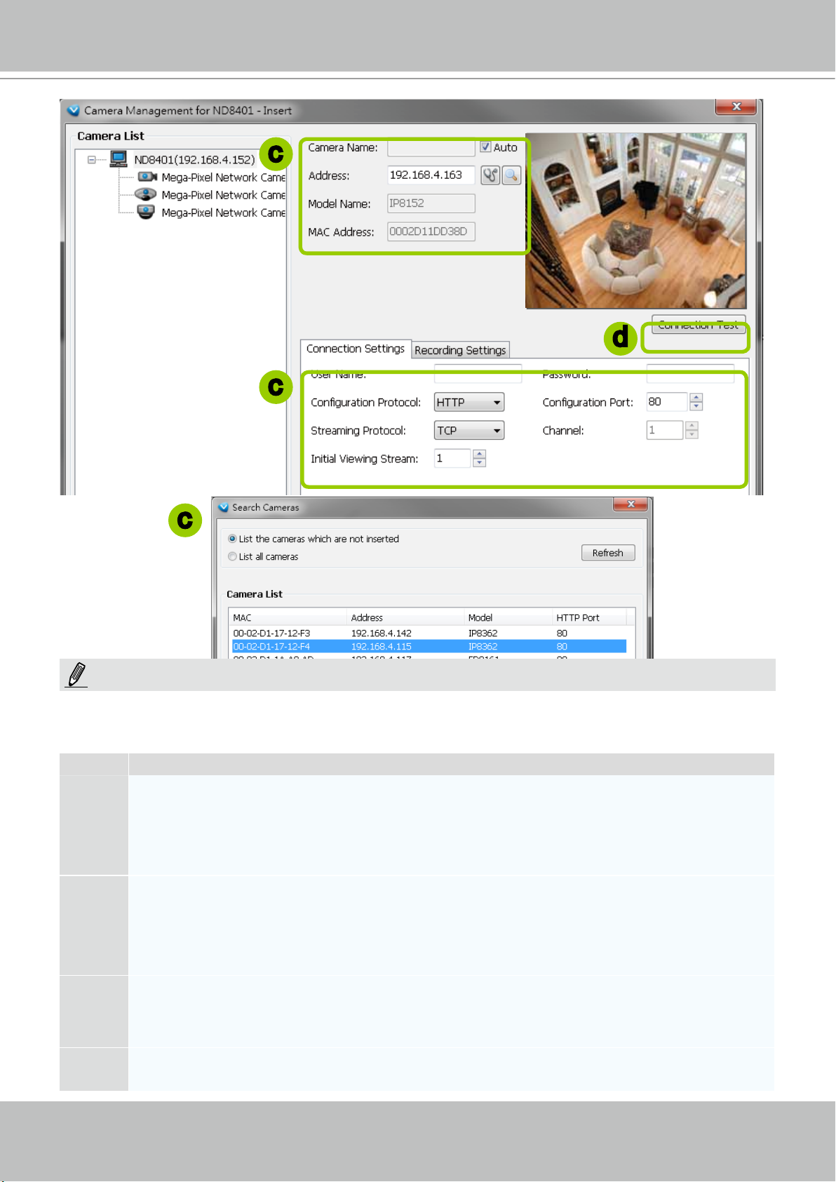
Insert Cameras
Please follow the steps below to add devices (cameras or video servers) to a station:
a. Click Conguration > Camera Management > Insert Camera on the menu bar (or right-click the
device/station, then select Camera Management > Insert Camera).
b. The Camera Management - Insert window will pop up. The device tree managed by the station will
be displayed in the Camera List window on the left.
c. Enter the Camera Name, IP address (or you can enter an IP address and check Auto to get a
camera name automatically) and congure the Connection Settings.
If the camera is on the LAN, you can click Search Camera to detect all VIVOTEK network
cameras on the LAN. A Camera List window will pop up and show a list of detected cameras on
the LAN. On the top of Camera List window, you can select "List the cameras which are not
inserted" or "List all cameras". The items listed below will then change accordingly. You can click
Mac, IP Address, Model, HTTP port to sort the items. Then select a camera from the list to insert
to the station.
The streaming protocol determines how the live video stream is sent from the camera to the local
computer. Please refer to the note on the next page for a detailed description of each transmission
protocol. Specify the recommended live monitoring stream for the device. If you want to change the
live viewing stream, please refer to the next page to update the camera settings. Or you can right-
click the desired view cell, then select a desired stream. Please refer to Dual / Multiple Streams on
page 53 for a detailed illustration.
Click Detect Model to detect the device. The Model Name and MAC Address of the device will
automatically be displayed in the respective elds if the connection is successful.
d. If you want to make sure you are connected to the target device, click Connection Test to preview the
live video from the device.
User's Manual - 37
Page 38
VIVOTEK
2010/12/10 17:08:56
c
d
c
c
NOTE:
If you want to use "HTTPS Port", please enable the HTTPs settings on the conguration page of a web console
with a Network Camera. Refer to the camera's User Manual for details.
The characteristics of each protocol are shown in the following table:
Protocol Description
UDP uses a simple transmission model without implicit hand-shaking dialogues for guaranteeing
reliability, ordering, or data integrity. Thus, UDP provides an unreliable service and data grams may
UDP
TCP
arrive out of order, appear duplicated, or go missing without notice. This protocol allows for almost
real-time audio and video streams. However, network packets may be lost due to network burst
trafc and images may be obscured. Activate UDP connection when occasions require time-sensitive
responses and video quality is less important.
TCP provides the service of exchanging data reliably directly between two network hosts, whereas IP
handles addressing and routing message across one or more networks. In particular, TCP provides
reliable, ordered delivery of a stream of bytes from a program on one computer to another program
on another computer. This protocol guarantees the delivery of streaming data and thus provides
better video quality. The downside with this protocol is that the real-time effect is worse than that with
UDP for a narrower bandwidth.
HTTP is a networking protocol for distributed, collaborative, hypermedia information systems. It’s the
HTTP
HTTPS
38 - User's Manual
foundation of data communication for the World Wide Web. This protocol allows for the same quality
as TCP and the users need not open a specic port for streaming under some network environment.
Users inside a rewall can utilize this protocol to allow streaming data through.
This protocol enables authentication and encrypted communication over SSL (Secure Socket Layer),
which protects streaming data transmission over the Internet on higer security level.
Page 39

VIVOTEK
e. Congure Recording Settings:
Recording Stream: By default, the stream source of the recording stream is stream 1, if you want to
change it later on, please refer to the previous page to update the camera settings.
Pre-event time: Enter a number to decide how much time to record before an event is triggered.
Post-event time: Enter a number to decide the duration of recording after an event is triggered.
e
pre-
10 sec.
Pre-event time
Trigger Activation
Post-event time
post-
10 sec.
NOTE:
Please note that if you want to enable activity adaptive stream, we suggest you right-click the camera on the
heirarchical management tree > Camera Settings to open a managment session. Move to Conguraion > Media
> Audio and Video to activate "Time Shift Cache Stream" on the camera and select a stream source. This will
help record complete pre-event recording.
Note that some of VIVOTEK's latest cameras
have this function enabled by default. No
conguration option is needed on the camera.
User's Manual - 39
Page 40

VIVOTEK
g
2010/12/10 17:08:56
f
i
g
f. The device will automatically be assigned to the default Storage Group. Deselect the item if you want
to cancel this setting.
g. When all settings are completed, click Insert to add the device to the station. The device will be
displayed under the Camera List on the left.
h. To insert more devices to the station, repeat the above steps.
i. When completed, click Close to exit the camera management window.
j. Return to the main window, you will nd the newly-inserted devices listed under the VAST station and
then you can click and drag cameras into the live cells.
Mega-Pixel Network Camera
40 - User's Manual
Page 41

VIVOTEK
Enable SVC
If the camera to-be-added supports the latest SVC (Scalable Video Coding) feature, select the
SVC checkbox to enable the related control. The SVC feature enables streaming of videos for
multiple clients from one single set of layered IP packets. Designed for saving bandwidth and
CPU load on client stations, the frame rate of a video stream appearing through a view cell
can be individually adjusted. This feature applies when an administrator experiences unstable
video streaming due to the lack of network bandwidth, less-than-ideal hardware, or during an
occurence of network problems.
30fps
Client PC
25fps
Notebook
5fps
3G Cell Phone
SVC Packet
Network Camera
LAN
VAST Server
LAN/WAN
Stream
on Demand
Stream
on Demand
Stream
on Demand
Stream
on Demand
60fps
NVR Storage
The VAST server automatically negotiates with a camera and determines whether a network
camera comes with the SVC feature. The SVC checkbox appears if the network camera
supports the feature. The same checkbox also appears in the Batch Insert Cameras window.
To congure the SVC-related feature:
1. When inserting a new camera into your conguration, click on the Detect Model button.
2. select the Enable SVC checkbox.
User's Manual - 41
Page 42
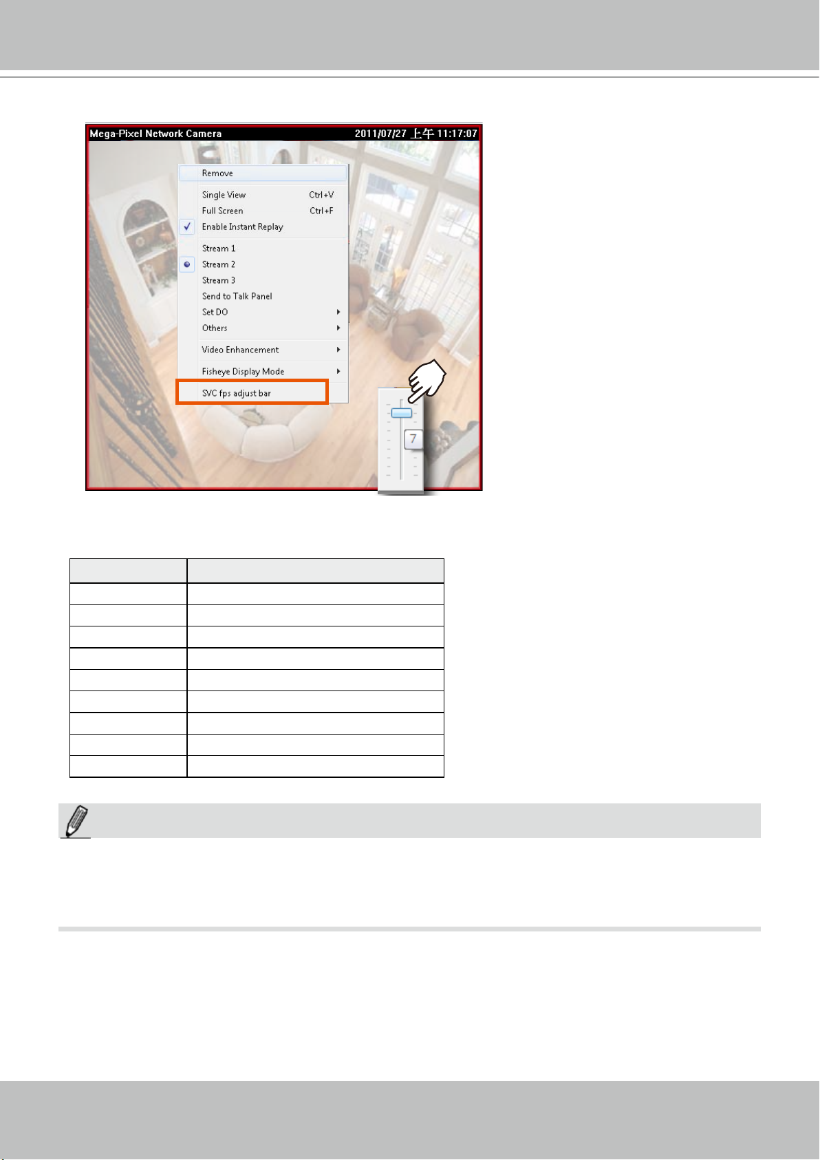
VIVOTEK
2.
Right-click on the view cell of an SVC-enabled camera. Select SVC fps adjust bar.
3. A slide bar will appear above the view cell. Click and drag the slide bar. A numeric indicator
will display the current selection. See below for the frame rates represented by the numeric
indicator.
Indicator Frames per second (fps)
Maximum 30
7 26
6 22
5 18
4 12
3 8
2 4
1 1
Minimum 1/4
NOTE:
The SVC feature only applies to video streams using VIVOTEK's proprietary SVC compression format.
It is not applicable to MPEG-4 streams. Please refer to Conguration -> Media -> Video for individaul
stream settings.
42 - User's Manual
Page 43
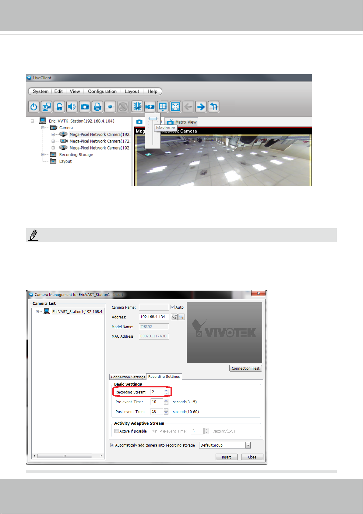
VIVOTEK
If you have multiple SVC-enabled cameras, you can enable a collective setting via the Adjust
SVC level button on the tool bar. The frame rate selected here will then apply to all view cells on
the VAST LiveClient console.
Please note that the SVC related setting can not take effect while the LiveClient station is
running the Layout Rotation. Stop the layout rotation before conguring the SVC function.
NOTE:
While you save your bandwidth for live viewing, you can still record full-frame-rate video by changing the
recording setting. For example, you can enable resource-saving SVC on stream #1 and congure stream
#2 to be recorded with full details, in terms of frame size, frame rate, and video quality. Please note that
you should use the Constant Bit Rate methodology to limit the size of recording stream to 6Mb per
second.
User's Manual - 43
Page 44

VIVOTEK
Update Devices
Please follow the steps below to update a device via Camera Management window:
a. Click Conguration > Camera Management > Update Camera on the menu bar (or right-click the
device/station, then select Camera Management > Update Camera).
b. The Camera Management - Update window will pop up. The device tree managed by the station will
be displayed in the Camera List on the left.
c. Select a device from the list you want to update. Its related information will automatically be displayed
in the corresponding fields in the Camera Management window. Then you can modify Connection
Settings and Recording Settings of the device.
d. After modifying the settings, you can click Connection Test to preview the live video from the device.
e. When all settings are completed, click Update to enable the settings.
a
b
c
d
44 - User's Manual
e
Page 45

VIVOTEK
Delete Devices from the Station
Delete a device:
Right-click the device on the device tree, then select Delete. A dialog box will pop up. Click Yes to
delete the device along with the recorded data; click No to delete the device but retain the recorded
data; click Cancel to cancel the delete action.
Delete more than one device at a time:
a. Click Conguration > Camera Management > Delete Cameras on the menu bar (or right-click the
device/station, then select Camera Management > Delete Cameras).
b. The Delete Cameras window will pop up.
c. Select the devices you want to delete from the list, then click Delete.
d. A dialog box will pop up. Click Yes to delete the device along with the recorded data; click No to delete
the device but retain the recorded data; click Cancel to cancel the delete action.
e. When completed, click Close to exit the Delete Cameras window and return to the main window. The
deleted device will disappear from the station.
b
d
a
c
e
User's Manual - 45
Page 46
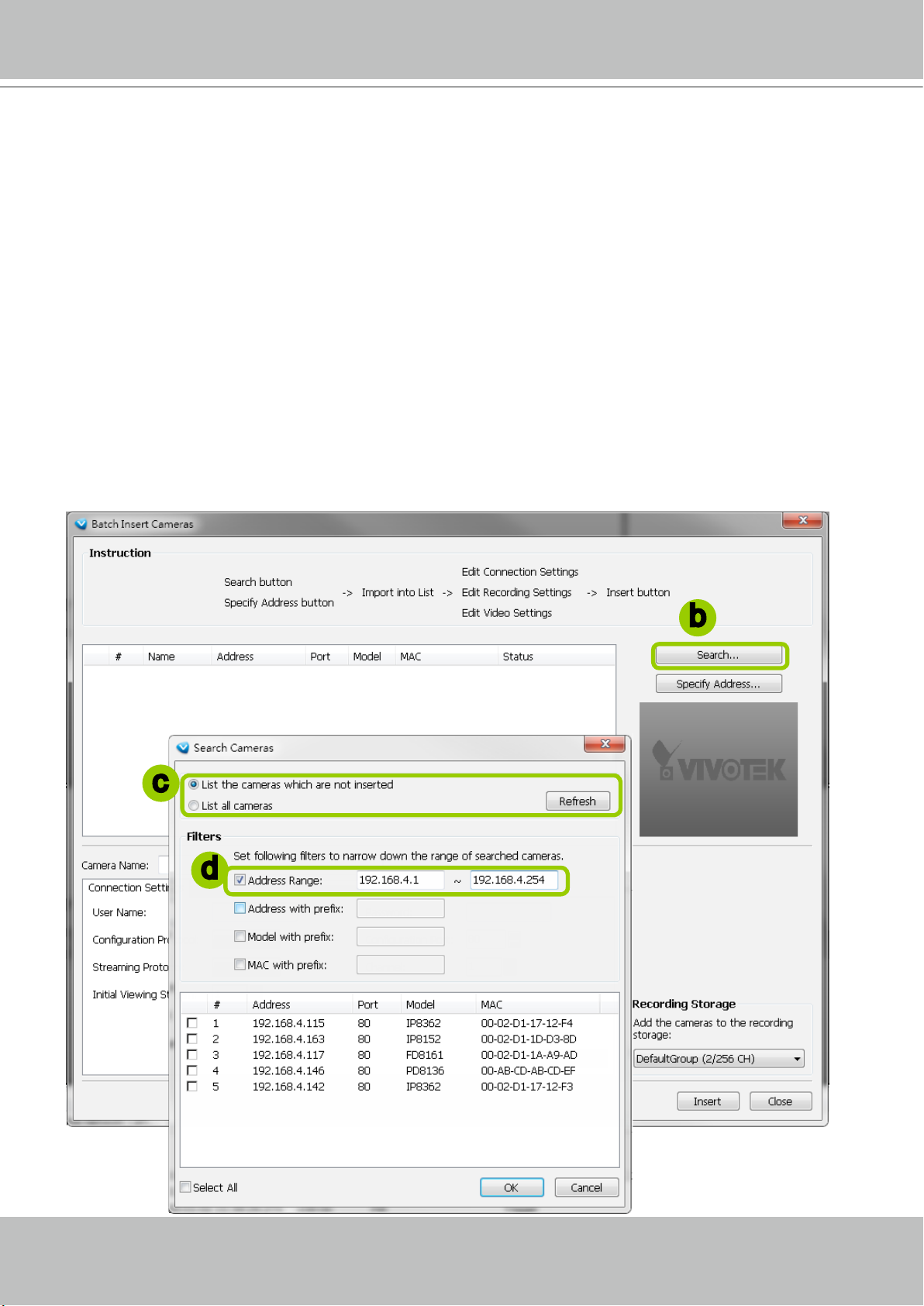
VIVOTEK
Batch Insert Cameras
Batch insert is a very useful function that allows user to search, filter, and import a row of
devices that are in the same LAN to an NVR station. Basic settings can also be applied to those
inserted devices simultaneously.
Please follow the steps below to batch insert devices to the station:
a. Click Conguration > Camera Management > Batch Insert Cameras on the menu bar (or right-
click the station, then select Camera Management > Batch Insert Camera).
b. The Batch Insert Cameras window will pop up. Then click Search to open the Search Camera
window.
c. On top of the Camera List window, you can select "List the cameras which are not inserted" or "List all
cameras". The items listed below will then change accordingly.
d. Use the 4 Filters to narrow down the range of the wanted cameras from the list.
IP Range: Key in a range of IP address to narrow down the list; the lter automatically applies after
you ll in a correct IP range.
c
b
d
46 - User's Manual
Page 47
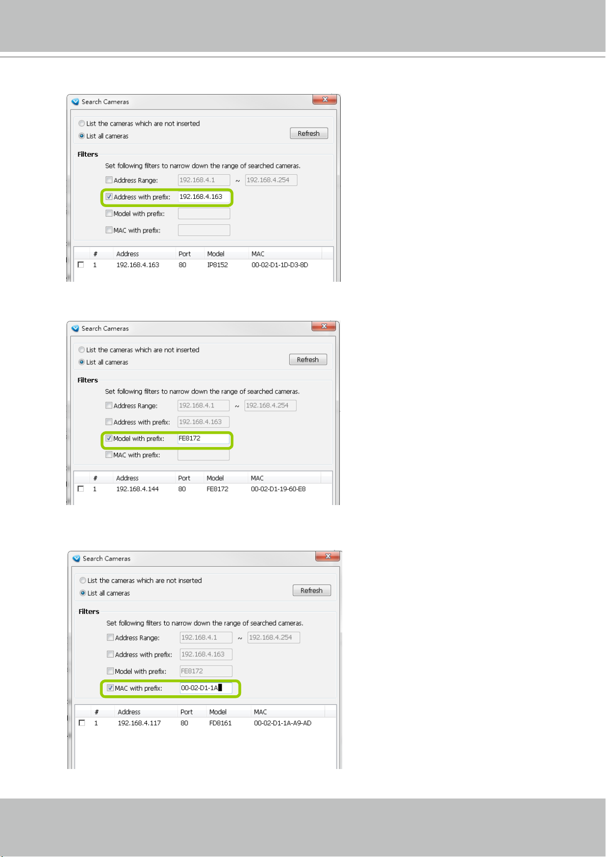
VIVOTEK
IP with prex: Key in in the prex of the IP address to narrow down the list.
Model with prex: The user can type in the prex of the model name or the complete model name of
the cameras to narrow down the list.
MAC with prex: You can type in the prex of the MAC address of the cameras to narrow down the
list.
User's Manual - 47
Page 48

VIVOTEK
e. When the list is ltered, you can select the cameras one by one or check Select All to add them to the
batch insert list. Then click OK to nish searching.
f. The selected cameras will be shown on the batch insert camera list with the camera information and
the connection status. When you click on a camera, a snapshot will appear up on the right side for you
to identify the cameras on the list. If you want to remove a camera from the list, click the trash can icon
to delete it.
f
h
g
48 - User's Manual
i
j
Page 49

VIVOTEK
g. At the bottom of the window, there is a eld for you to alter the camera settings including Connection
Settings and Recording Settings. You can apply the new settings to each camera on the list, or
click Apply to All to apply the same congurations to all the cameras. For more information about
Connection Settings and Recording Settings, please refer to Insert Device on page 37 for detailed
information.
h. Specify host: If you want to add a camera to the list, click Specify
Address to directly add a wanted camera. Click Add after lling in
the correct information. The camera will be added to the list of the
Batch Insert Camera window.
i. By default, all inserted devices will be applied to the default
recording storage. Deselect the Add checkbox if you do not want
to assign the selected devices to the default recording storage.
j. Click Insert when all the settings are done. Cameras will be added.
NOTE:
When you modify the camera settings, and when the connection information (Conguration Protocol and
Conguration Port) does not match the current network environment, the camera will be disconnected and the
status of the camera will become “Camera cannot be found” as shown below.
User's Manual - 49
Page 50

VIVOTEK
Camera Conguration
The Camera Conguration function group provides immediate access to the video streaming and other
settings without the need to open a web console. The function group is accessed by selecting a camera
on the device tree, and right-click to select Camera Management > Camera Conguration.
FOV (Field of View)
The FOV configuration is available for 5 megapixel cameras (such as FE8172, IP8372, and IP8172P),
which allows you to crop a portion of the image captured by the sensor. The FOV setting applies in the
scenario where you do not need all of the video a camera can capture. For example, when shooting a
parking lot where the upper half of the image is the sky. Cropping a field of view can help save bandwidth
and reduce the requirements for storage space.
50 - User's Manual
Page 51
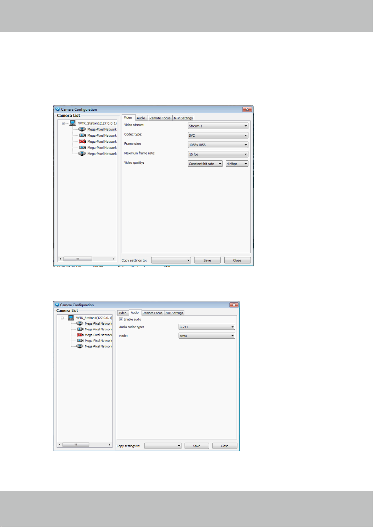
VIVOTEK
Video
This tabbed window privides access to the selection of the live view stream, its compression codec,
frame size, max. frame rate, and video quality. Note that the Constant Bit Rate methodology can be
used to ensure that the size of video stream does not exceed a preferred threshold, regardless of the
complexity or the changes of pixels in the image. You should use a maximum of 1080P as frame size
and 6Mbps as constant bit rate for video streams managed by this system.
Audio
If audio feed is preferred, configure the audio codec type and operating mode in here.
User's Manual - 51
Page 52

VIVOTEK
Remote Focus
For cameras supporting the remote focus feature, such as the FD8362E that comes with a motorized
lens, this window provides finetune buttons and full-range scan fucntion to help reach the best image focus.
NTP Settings
If cameras’ real time clocks are set to be synchronized with a time server, enter the NTP server’s address or domain name and specify an Updating interval. If you select the “Synchronize camera time with
system automatically” checkbox during the initial setup, the NTP server IP will be the NVR’s IP.
Always remember to Save your configuration before leaving this window. You can also use the “Copy
settings to” button below to duplicate your current settings to adjacent cameras.
52 - User's Manual
Page 53

VIVOTEK
View Live Videos
You should double-click on the target device or drag-and-drop the target device from the
hierarchical management tree window to a video cell.
Mega-Pixel Network Camera
Dual / Multiple Streams
For multiple-stream devices, you can right-click on the focused view cell to select a stream. The NVR
system automatically selects a video stream depending on the size of the current layout and view
window. Normally it is not necessary to change the video stream.
Mega-Pixel Network Camera
Fisheye Display Modes
By default, a round view is displayed when a fisheye camera is successfully connected. To
display Regional, Panoramic, or the combination of different views, right-click on a fisheye
camera's live view to display the associated commands. The display modes available are: 1O
(Original), 1P (Panoramic), 1R (Regional), 2P (2 Panoramic), 1O3R (1 Original & 3 Regional),
1P3R (1 Panoramic & 3 Regional), 4R (Quad Regional), 1O8R (1 Original & 8 Regional), and
4R Pro (4 Proactive) modes.
User's Manual - 53
Page 54

VIVOTEK
Fisheye Display Modes: below are conceptual drawings for different display modes.
1O (Single Original) Display mode: 1R (Single Regional) Display mode:
An Original oval view covers the
hemisphere taken by the sheye
lens.
1O View (Original View)
180° Hemispheric
A Regional view crops a portion of the hemisphere
as a region of interest. You can zoom in or out or
move the view area elsewhere from on the regional
view.
1R View (Single Regional View)
Zoom In
Zoom in/out
&
all-direction
navigation control
Zoom Out
A Regional view is dewarped, by correcting images
from the distorted oval view to a rectangular and
visually proportional image.
1P (Single Panoramic) Display mode:
With image correction algorithms in rmware, the hemispheric image is transformed into a
rectilinear stripe in the 1P display mode. Viewers can use the PTZ panel or simply use mouse
control to quickly move through the 360º panoramic view.
Note that the 1P view is apt for an overview, the Zoom in/out function does not apply in this
mode.
1P (Panoramic) Mode Screen Control
Swipe to scroll horizontally
54 - User's Manual
Page 55

VIVOTEK
2P (2 Panoramic) Display mode:
Two dewarped rectangular views are placed one on top of another each showing 180 degree of
panoramic view. The 2P view looks like the upper view shows the front of hemisphere, and the
lower view the rear half of the hemisphere.
2P (Panoramic) Mode Screen Control
Swipe to scroll horizontally
1O3R (One Original & 3 Regional) Display mode:
Fisheye cameras also support the display of multiple regional views taken from within the same
hemisphere, and they can be displayed with or without an Original view in its view cell.
3R View (Regional View)
Zoom in/out
&
all-direction
navigation control
* Only two regional views are shown for simplicity reason
User's Manual - 55
Page 56

VIVOTEK
PTZ Mouse Control
The "Mount type" setting also determines the display modes available to your sheye cameras.
Please refer to sheye camera's User Manual for more information.
A highly versatile mouse control is implemented with sheye cameras. The same control takes
effect on a browser management session, on the LiveClient utility, and even on a video playback
screen. See the drawing below for how it works.
You can click and hold down the left mouse button to quickly swipe through the eld of view,
change the view angle, or use the mouse wheel to zoom in/out on a region of interest. However,
the PTZ mouse control is only available in the "R" (Regional) mode. In the Panoramic mode,
you can only scroll horizontally across the 180º or 360º panoramic view.
1O3R (Original & Regional) Mode Screen Control
Zoom In
Click to bring into
center of view
Zoom Out
NOTE:
3
Pan or tilt
1
Interactive
regional FOV indicators
2
Current screen selection
Click, hold down
the button, and drag
The various display modes require the support of D3D technologies by your display card. Most
off-the-shelf display cards today support this feature.
The onscreen mouse control is very agile. Therefore, use the PTZ panel for more delicate
moves in a field of view. Pan and Patrol moves are also supported if you have configured
preset PTZ positions in the camera's firmware. Note that the Pan move takes place in the
Panoramic and Regional views, while the Patrol function through preset positions applies only in
the Regional views.
56 - User's Manual
Page 57
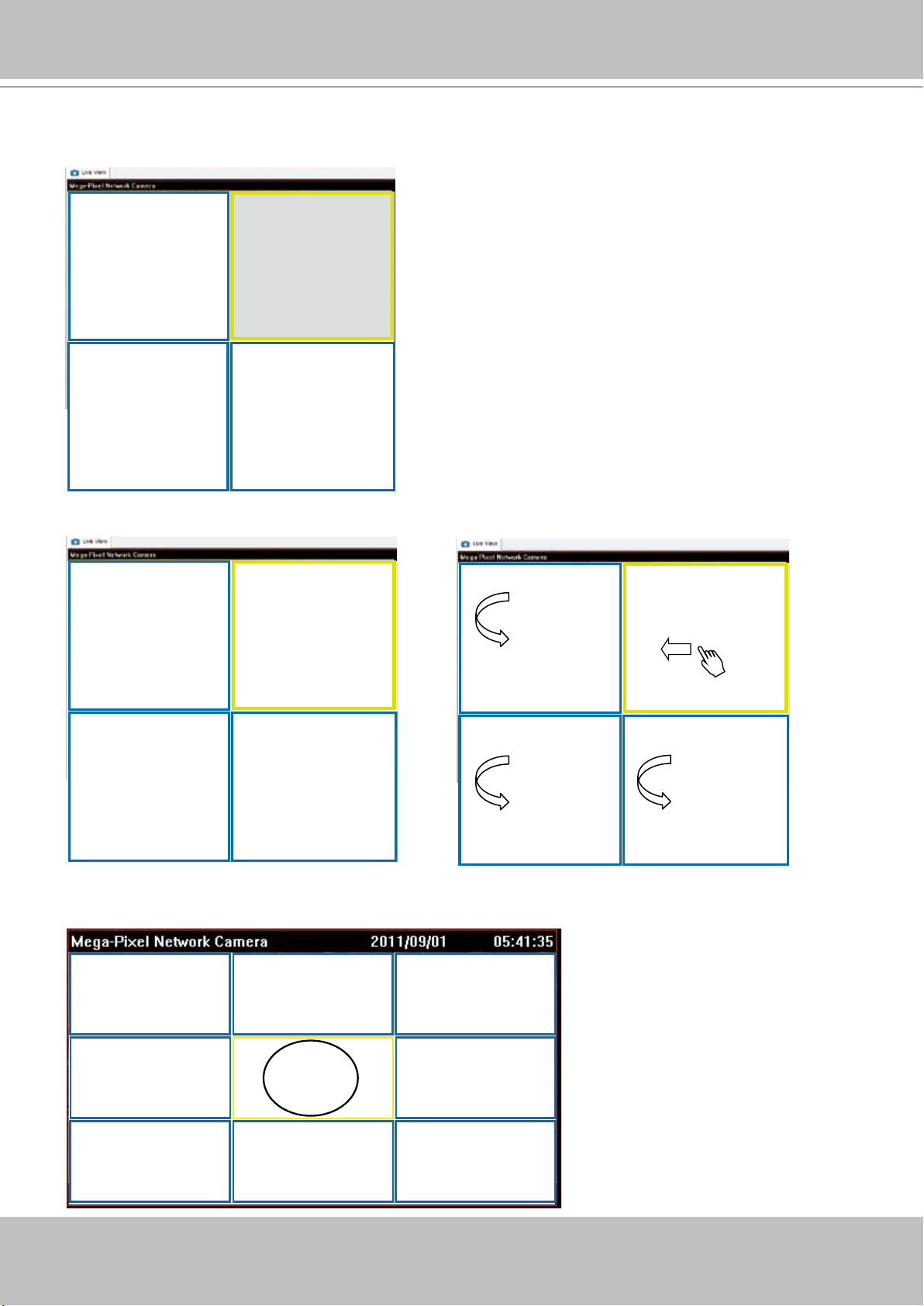
Below are the conceptual drawings for other display modes:
1P3R (One Panoramic & 3 Regional) Display mode:
VIVOTEK
Regional View #1
Panoramic View
Regional View #3Regional View #2
4R (Quad Regional) Display mode:
Regional View #2
Regional View #1
4RPro (4 Regional Proactive) Display mode:
Regional View #2
Regional View #1
Regional View #3
Regional View #4
1O8R (One Original & 8 Regional) Display mode:
Regional View #3
Regional View #4 Regional View #8
Original View
Regional View #6Regional View #5 Regional View #7
Regional View #1Regional View #2
Regional View #3
Regional View #4
User's Manual - 57
Page 58

VIVOTEK
NOTE:
For Fisheye video playback and recording concerns, refer to page 132 and page 179.
Refresh
Right-click the device, then click Refresh, the camera information will be refreshed from the server.
Streaming Server
Right-click the station or the device and click Output Streaming URL. A .txt le with streaming URL will
pop up. Then you can use this URL to link to the live streaming through QuickTime Player.
Get Public IP
If your access to Internet is via PPPoE, this function will display the public IP provided by your service
provider. If your access to Internet is via a router, please consult your network administrator or consult
your ISP for a valid public IP.
58 - User's Manual
Page 59

VIVOTEK
Camera Settings
Right-click the device, then click Camera Settings to open a brower's session to the camera.
Remove Live Video from the Video Monitoring Window
There are two ways to remove a live video from the video cell:
Method 1. Right-click the video cell and select Remove.
Mega-Pixel Network Camera
Method 2. Drag-and-drop the live view from the video cell to the hierarchical management tree window.
Mega-Pixel Network Camera
NOTE:
If you want to remove all live videos from the video cells, please click on the menu bar.
User's Manual - 59
Page 60
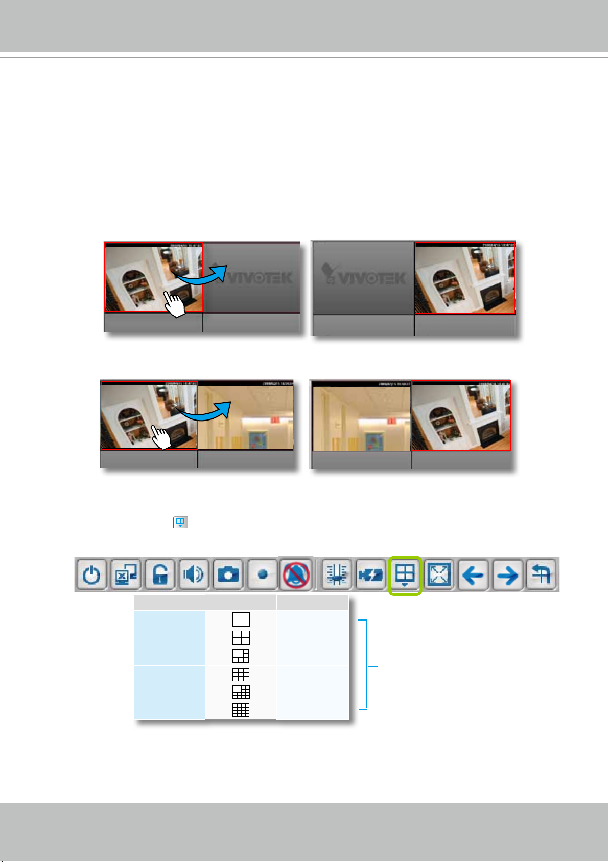
VIVOTEK
How to Change the VAST LiveClient Layout
Changing the Layout of the Live Video Monitoring Window
The NVR's LiveClient supports up to 6 simultaneous video viewing on a single monitor and
allows you to change the layout of the live video monitoring window based on the number of
inserted devices.
Switch Video Channels
To move a video channel to another empty video cell, drag-and-drop the view to the target video cell.
To switch two different channels, drag-and-drop one view to the other, then the two different channels
will be switched to the opposite.
Congure Layout Mode
Click the Layout button on the quick access bar. Select a desired layout mode, and the layout
window will change accordingly. Below we illustrate 6 types of layout modes and the corresponding page
numbers:
Layout mode Description Video page
1 x 1
2 x 2
1 + 5
3 x 3
1 + 12
4 x 4
32
8
4
3
2
2
More than 1 video page;
rotation function is enabled
Some layout modes (1 x 1, 2 x 2, 1 + 5, 3 x 3, 1 + 12, 4 x 4) will spread the view cells of video channels
over several pages.
60 - User's Manual
Page 61
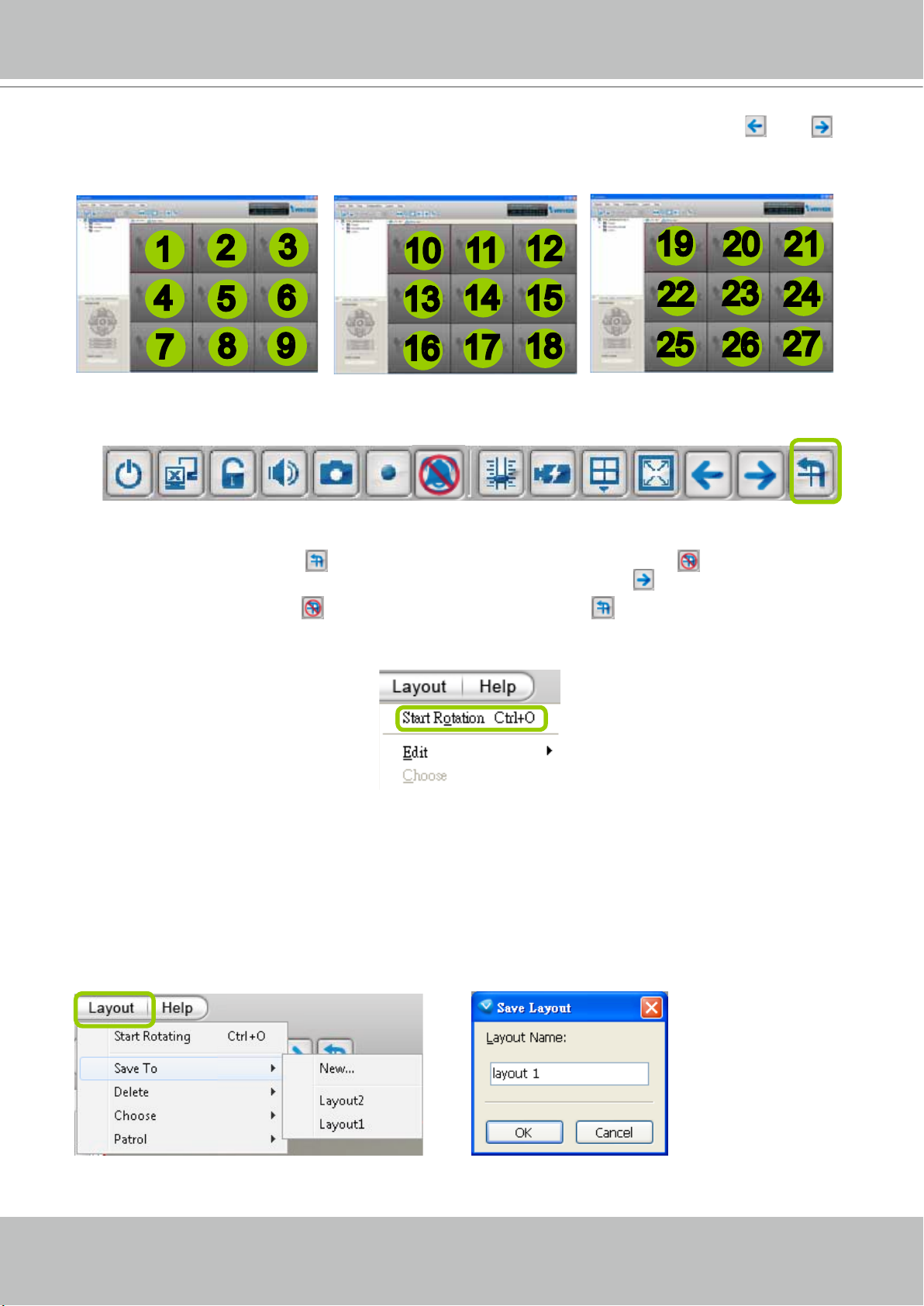
VIVOTEK
For example, under the 3 x 3 layout mode, you can switch among the pages by clicking and on
the quick access bar. To arrange the content of each page, manually drag-and-drop cameras from the
hierarchical device tree to the video cells on each page.
Page 1 Page 2
Page 3
1
4
7
Rotating Video Pages
For layout modes that contain more than one page, the LiveClient offers the rotating function for
displaying all video pages in turn.
To enable this function, click on the Quick Access Bar, which will become Stop Rotating, and
the video pages will start to rotate so that the user does not have to click
To disable this function, click Stop Rotating, which will become on the Quick Access Bar.
You can also click Layout > Start to Rotate/Stop Rotating to enable/disable this function.
2
5
8
3
6
9
10
13
16
11
14
17
12
15
18
19
22
23
25 26
to move to the next page.
2120
24
27
The default rotating time interval is 6 seconds. If you want to edit rotation settings, please refer to
Rotation Settings on page 135.
Edit Layout
Please follow the steps below to save a layout:
a. Arrange a layout mode and drag devices to their desired video cells.
b. Click Layout > Edit > Save to > New on the menu bar. A Layout Name dialog box will pop up.
c. Enter a name for the the layout, then click OK to enable the setting.
User's Manual - 61
Page 62
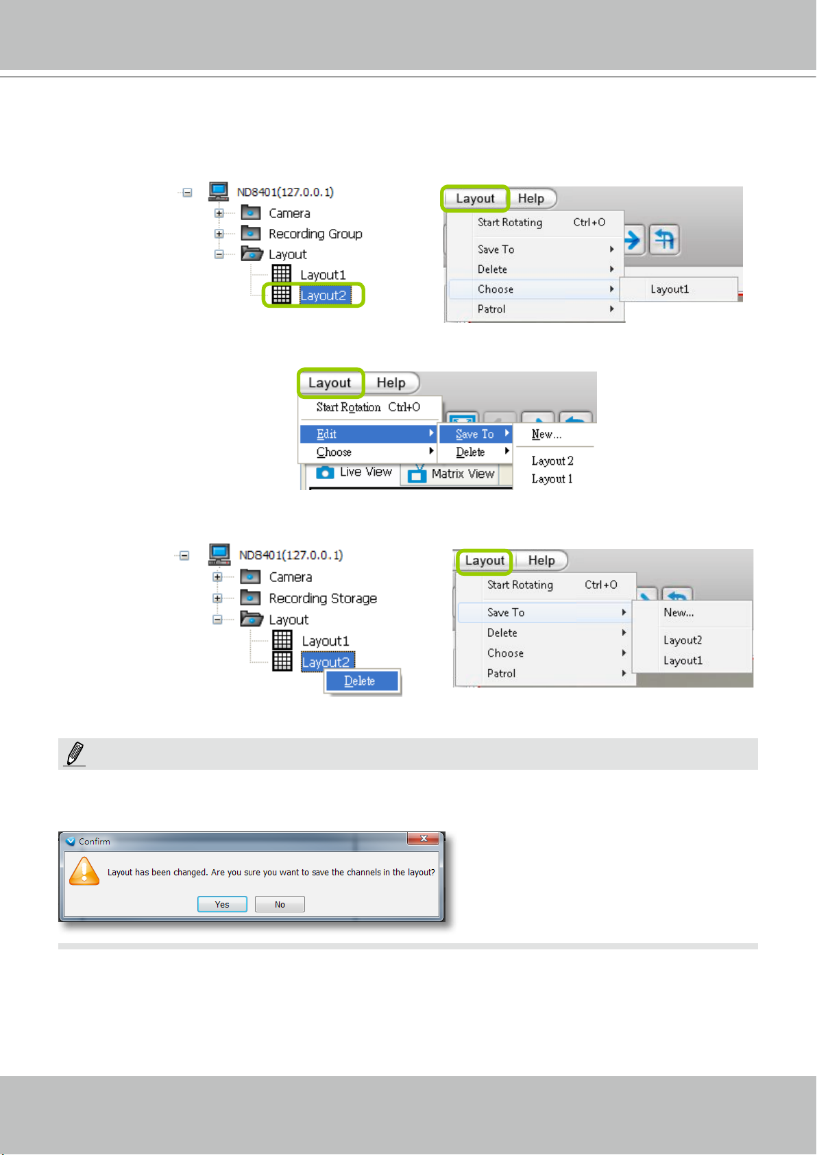
VIVOTEK
d. Back to the monitoring window, the new layout will appear under the device tree as shown below. You
can save up to 10 layouts.
e. To change to another layout, double-click the layout options on the hierarchical management tree, or
click Layout > Choose on the menu bar to select a desired layout.
If you want to edit an existing layout, arrange a layout mode and drag devices to the desired video
cells, then click Layout > Edit > Save to > New to save as a new layout or an existing layout to
replace with the new one.
If you want to delete an existing layout, right-click the layout item on the hierarchical management
tree or click Layout > Edit > Delete on the menu bar to delete it.
NOTE:
Whenever you close the LiveClient or Playback programs and changes in screen layout have been
made, you will be prompted to save your current conguration.
62 - User's Manual
Page 63
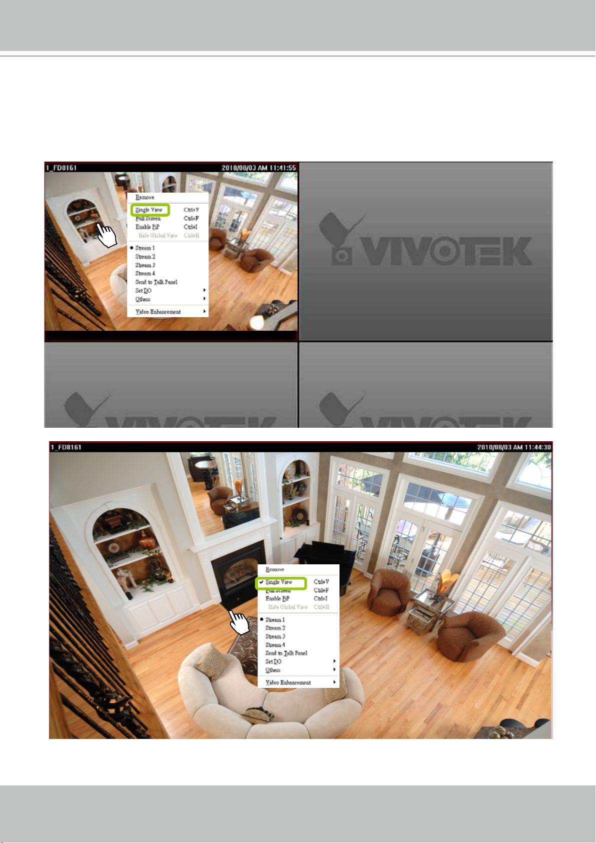
VIVOTEK
Maximize the Live Video Monitoring Window
Single View: to maxmize a video cell to the entire live video window
Double-click the video cell, or right-click the video cell and select Single View. The focused video will
occupy the entire playback window as shown below.
To restore to the original layout, double-click the video cell or right-click the video cell and uncheck
Single View.
User's Manual - 63
Page 64

VIVOTEK
Full Screen: Maximize the live video monitoring window to the entire screen
Click Full Screen
on the quick access bar or right-click the video cell and select Full Screen. In
addition, you can also click View > Full Screen on the menu bar to maximize the live video monitoring
window.
To restore to the original layout, you can right-click a video cell and uncheck Full Screen or click the
Esc button on the keyboard to exit full screen mode.
64 - User's Manual
Page 65
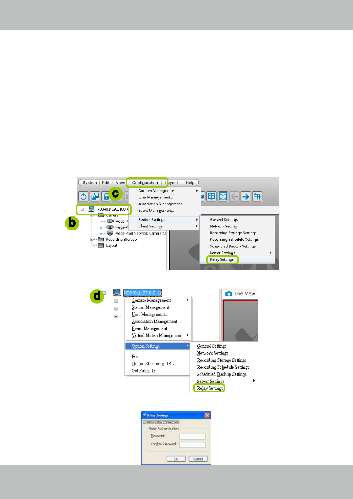
VIVOTEK
How to Manage Stations
A standard VAST Server allows you to construct a hierarchical management system by adding
more sub-stations to the root station. The NVR system can be included into a hierarchy
managed by a dominating VAST server. The NVR system itself can not manage other sub-
stations.
Relay Settings
Before adding a sub-station, please follow the instruction below to enable the sub-station's
Relay Settings rst.
a. Login to the sub-station.
b. Select the station from the hierarchical management tree.
c. Click Conguration > Station Settings > Relay Settings on the menu bar (or right-click the station
on the hierarchical management tree and select Station Settings > Relay Settings).
c
b
d
d. The Relay Settings window will pop up. Check Allow Relay Connection and enter a Password.
Then click OK to enable the settings.
User's Manual - 65
Page 66

VIVOTEK
How to Manage User Accounts
VAST on NVR allows users to apply multiple user accounts to a station with five levels of
user roles: Administrator > Power User > User > Operator > Guest. Each role has different
permissions listed as shown below. Moreover, Administrators have the highest privileges, while
Power Users can only add/edit users as Power Users, Users, Operators, and Guests.
The Default User Roles and Permissions of User Accounts
Functions \ User Roles Administrator Power User User Operator Guest Description
User Management
Camera Management
Association
Management
Access Event
Management
Modify Event
Management
General Station
Settings
Station Network
Settings
Access Recording
Storage/
Recording Schedule
Settings
Modify Recording
Storage/
Recording Schedule
Settings
Manually Record
Scheduled Backup
Settings
Access Server Settings
Modify Server Settings
Relay Management
Client Settings
Video Enhancement
Settings
Manage user accounts
Insert and congure the
camera settings
Access and modify the
association settings
Access event management
Modify event management
Modify general station
settings
Modify network settings
Access the Storage Group
and recording schedule
Congure the Storage
Group and recording
schedule
Enable the recording
function manually
Congure backup schedule
Access server settings
Modify server settings
Allow user to manage
station relaying settings
Congure the client
settings: snapshot, AVI,
etc.
Allow user to edit prole for
video enhancement and
assign prole to camera in
LiveClient
66 - User's Manual
Page 67

VIVOTEK
Privileges \ User Roles Administrator Power User User Operator Guest Description
Modify Directories
Delete Camera
Add, remove and rename
directories
Delete camera from the
station
PTZ control for PTZ
PTZ Control
cameras and speed domes
in LiveClient
Control the digital output or
Device Control
white light/IR illuminators of
the cameras
Talk Control
Access Camera
Conguration
Modify E-map
Event Search
Log Viewer
Backup
Two way audio function for
the cameras
Access the camera settings
Allow user to modify the
E-map
Use built-in search engine
to search specic events
Use built-in search engine
to search the log
Back up database manually
Record live stream or
Record/Export Media
export playback stream to
local les
Playback Authority
Allow user to access
Playback
User's Manual - 67
Page 68

VIVOTEK
Manage a User Account
Add a New User Account
a. Select the station from the hierarchical management tree.
b. Click Configuration > User Management on the menu bar (or right-click the station, then select
User Management).
b
b
a
c. The User Management window will pop up. The user accounts under the station will be displayed
under the left User List tree.
d. Enter the User Name, Password, and specify the User Role of this user.
e. Click Add to add the user account to the station. It will be displayed under the User List.
c
d
68 - User's Manual
e
Page 69

VIVOTEK
e
Permission of the User Account
Administrator is granted with all access privileges, while other user roles' permission is limited. If
you want to modify the permission, please login as the Administrator to congure the settings.
f. Select a User account from the User List tree.
g. If you want to set the limit of the permission
of the user, click Permission tab to check or
uncheck the items.
h. If you want to limit the devices accessible
by the user, click Accessible Cameras tab to
select the desired devices.
h
User's Manual - 69
Page 70

VIVOTEK
NOTE:
If you want to remove access permission mentioned above from the account, the user will not be able to
operate some functions listed in the following warning dialog.
j. When completed, click Update to enable the new settings.
i
jk
Delete the User Account
k. Click Delete, a delete user dialog will pop up. Click OK to delete the user account.
NOTE:
If the Administrator modies or deletes the User Account, that modied user might be kicked off from the station.
70 - User's Manual
Page 71

VIVOTEK
How to Set up Association Management
The LiveClient supports association management which allows the user to configure relative
event trigger notifications of the connected network devices. (E.g., DI/DO status on the
management tree, motion detection windows appearing in the video cell, or the event list in the
event window)
Association Management
Please follow the steps below to congure assocation settings:
a. Select the station from the hierarchical management tree.
b. Click Configuration > Association Management on the menu bar (or right-click the station and
select Association Management).
b
b
a
c. The Association Management window will pop up. Check or uncheck the items and click Save
to enable the settings. The items you've selected will also be displayed under the hierarchical
management tree.
For example:
d
/
/
d. If you want to rename the DI device, select the DI item and click the Rename button. It will be very
convenient for you to recognize the target DI device.
Digital input on / off
Digital output on / off
User's Manual - 71
Page 72

VIVOTEK
NOTE:
To manually enable DI/DO settings, please right-click the video cell and select Set DO to enable (Trigger) or
disable (Normal) the digital output of the linked device.
Before you congure the DI/DO Settings for VAST, please enable DI/DO congurations on your network device
and set up the camera correctly on the conguration page. You can right-click the device and click Camera
Settings to open the conguration page.
72 - User's Manual
Page 73
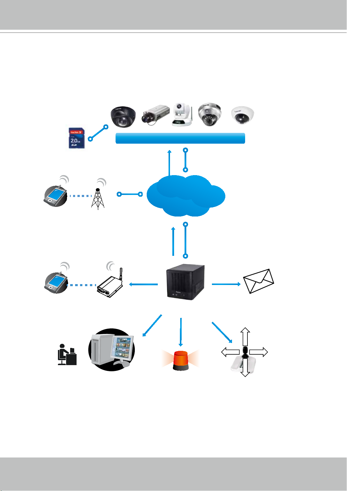
VIVOTEK
Tampering, PIR, Temperature...
How to Set up Event Management
The NVR's LiveClient supports event management which allows the server to respond to
particular situations (events). LiveClient can correspond with cameras' input and respond with
associated reactions, such as sending notications, telling cameras to move to preset locations,
etc.
Record on local
VIVOTEK Network Cameras
3G Cell phone
Cell phone
Short message
Move to preset
GSM
Modem
locations
HTTP
Camera Status, Motion,
DI/DO, Video loss,
Internet
NVR
Email
Client notification
Digital output
PTZ
User's Manual - 73
Page 74
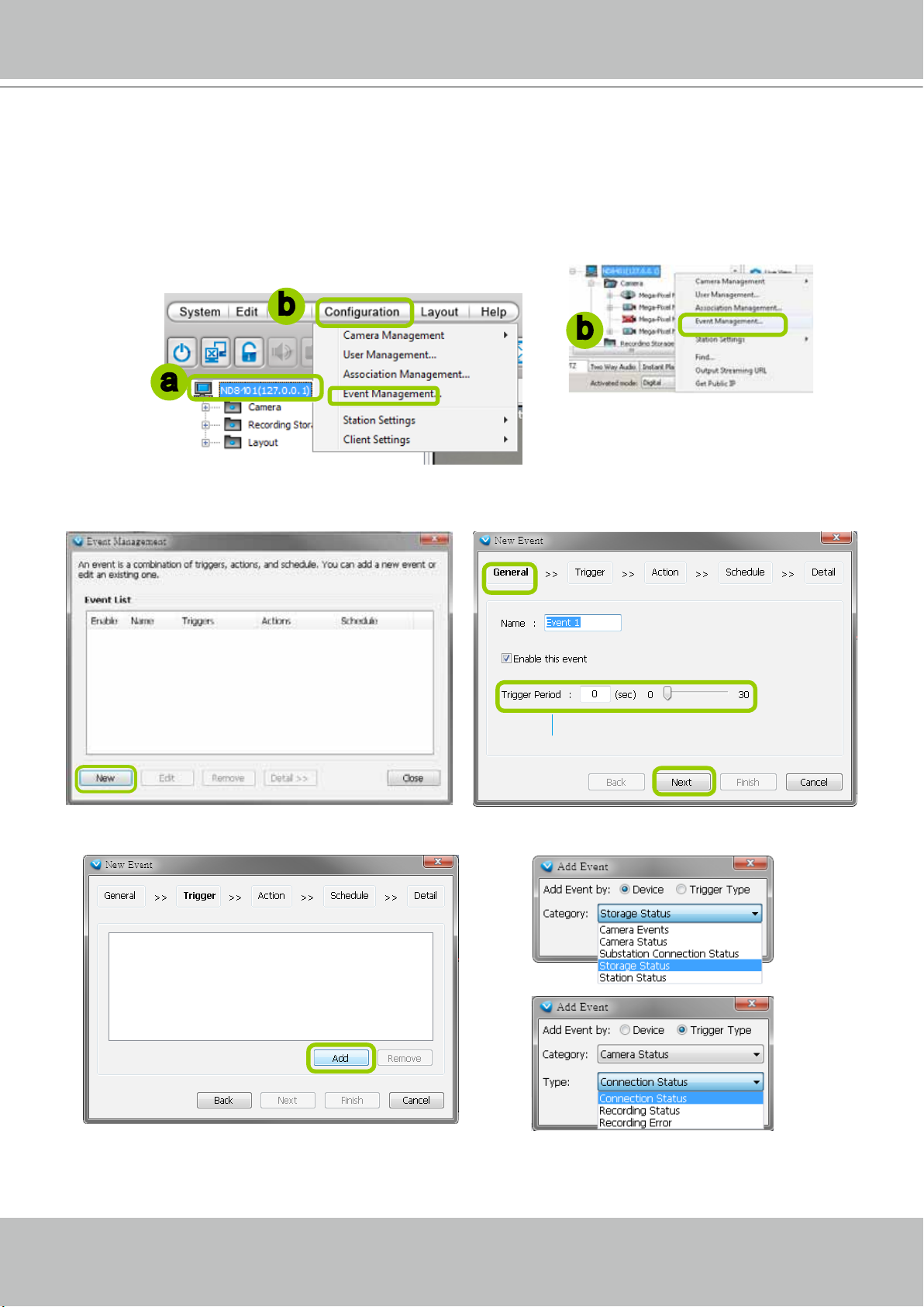
VIVOTEK
Event Management
Please follow the steps below to congure event management:
a. Select the station from the hierarchical management tree.
b. Click Configuration > Event Management on the menu bar (or right-click the station and select
Event Management).
b
b
a
c. The Event Management window will pop up. Click New to set up a new event. When you nish the
general settings, click Next to set up trigger source settings.
Detect next event after 5 secs
d. Click Add to select the trigger source by Device or Trigger Type.
74 - User's Manual
Page 75

e. The Device List window will prompt. Select one or more
devices and set the Notification Type. Depending on the
trigger source, the Notication Type will be different. Then
click OK to close the window.
f. The trigger source(s) will be listed on the window as shown
below. If you want to add more Trigger sources, click
Add and repeat steps d.and e. Then click Next to assign
action(s) to the trigger source(s).
g. Click Add to open the Action Settings window.
VIVOTEK
f
g
There are several options with the Action Settings.
Email: The sever will send a notication via e-mail when a trigger is activated.
h. To enable this function, please set up the SMTP server first. Click SMTP Setting to open the
window and refer to page 112 for detailed information.
i. Enter the related informtaion. You can modify the mail content in the blank. If you want to modify the
content, click Insert Macro to select the parameter. When completed, click OK on the bottom to
enable the setting.
h
i
User's Manual - 75
Page 76

VIVOTEK
Start to record on: The sever will start to record video from selected camera(s) when an event is
triggered.
j. Click Add Camera to select the target camera(s).
k. The selected camera(s) will be listed on the left window below. When completed, click OK at the
bottom to enable the setting.
j
k
j
k
Move to preset location: The target camera(s) will move the shooting area to the preset location(s)
when an event is triggered.
l. To enable this function, please set preset locations on the camera conguration page rst.
m. Click Add Location to select preset location(s).
n. The selected preset location(s) will be listed on the left window below. When completed, click OK at
the bottom to enable the setting.
m
n
Set DO: Select this option to turn on external digital output device(s) when an event is triggered. For
more information about how to set DI/DO settings on the target camera, please refer to page 71.
o. Click Add DO to select DO decive(s) and select a DO status (Normal or Trigger).
p. The selected DO device(s) will be listed on the left window below. When completed, click OK to
enable the setting.
n
p
o
o
76 - User's Manual
p
Page 77
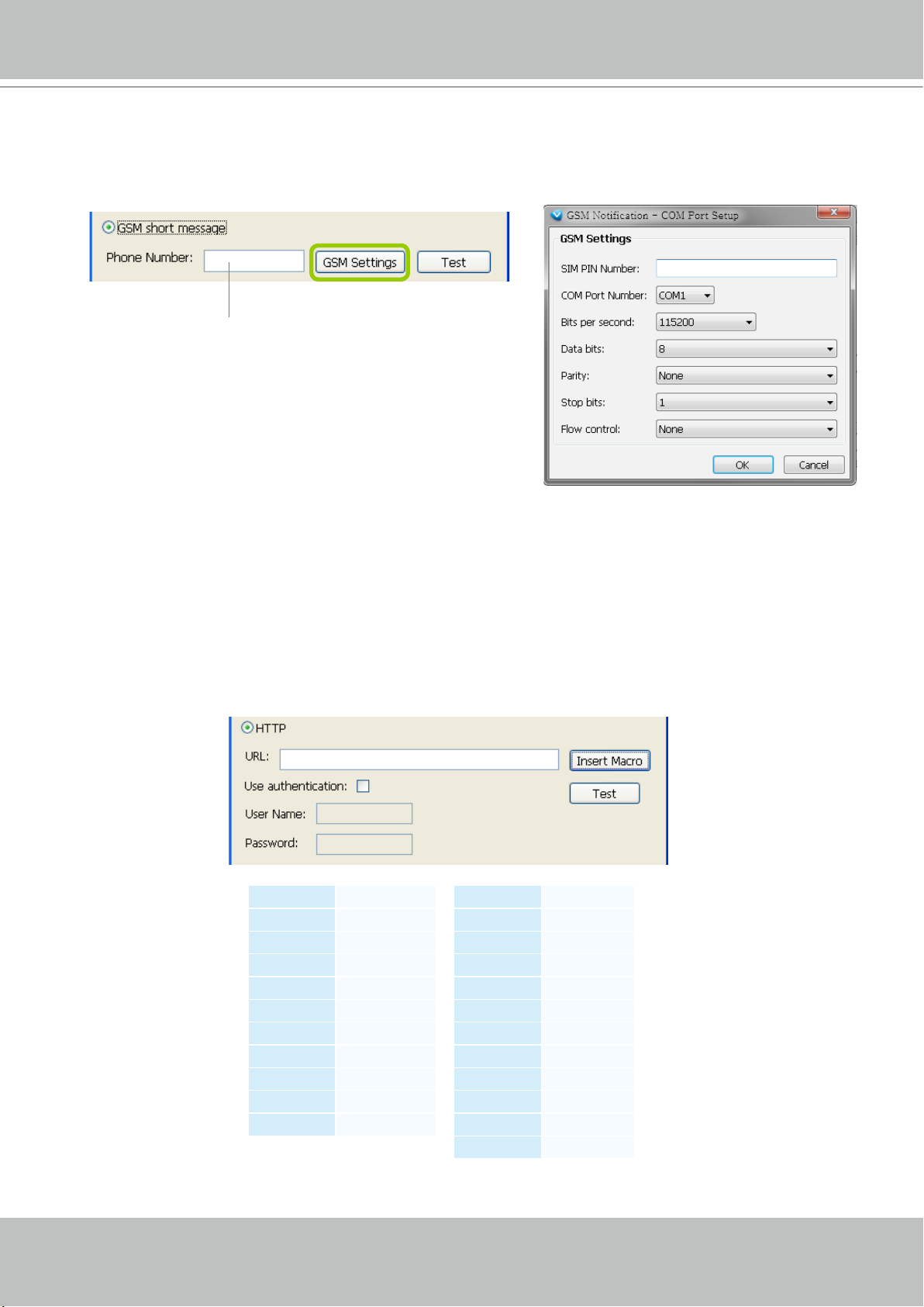
VIVOTEK
GSM Short Message: The sever will send a short message to a GSM cell phone when an event is
triggered. A GSM modem is necessary.
q. Please enter the Phone Number and open GSM Settings window to set related information if
necessary. When completed, click OK to enable the setting.
Please enter the country code if you use overseas call.
HTTP: This function allows user to send a CGI command to the linked network camera, such as pan/
tilt/zoom function or enable DO devices.
r. You can click Insert Macro to select the parameter. Please enter authentification information
if necessary. For example: http://192.168.3.66/cgi-bin/admin/setparam.cgi?system_
hostname=$(EventTime) $(CameraName)
If you want to use special characters such as $-_.+!*'(),#%+$,@:;/?=&, please refer to the
following table to transfer the Code (Hex).
For example: http://192.168.3.66/cgi-bin/admin/setparam.cgi?system_hostname=123&456
--> http://192.168.3.66/cgi-bin/admin/setparam.cgi?system_hostname=123%26456
Character Code (Hex)
! 21
# 23
$ 24
% 25
& 26
' 27
( 28
) 29
* 2A
+ 2B
Character Code (Hex)
, 2C
- 2D
. 2E
/ 2F
: 3A
; 3B
= 3D
? 3F
@ 40
_ 5F
~ 7E
User's Manual - 77
Page 78
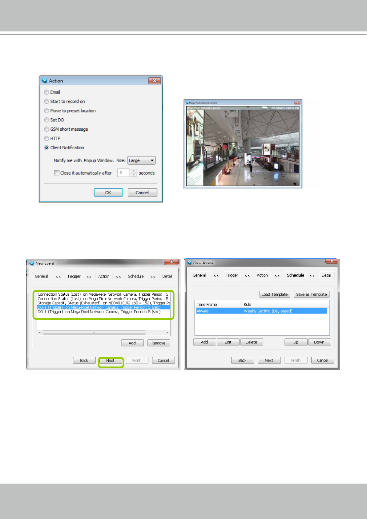
VIVOTEK
Client Notication: This function allows a notication video cell to prompt when an event is triggered.
You can select the size of the video cell, and select how long the view cell will stay on top of the
screen.
s. The action(s) will be listed in the window as shown below.
Then click Next to set up schedule(s) to the action(s).
For more information about Schedule Settings, please refer to Recording Schedule Settings on page
89. You can assign more than one time frame during twhich an action will take effect.
78 - User's Manual
Page 79
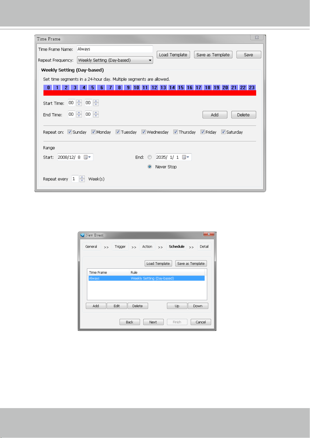
VIVOTEK
t. When you finish schedule settings, click Next to review the detailed information of the new event
settings.
User's Manual - 79
Page 80

VIVOTEK
u. Following is the detailed information of the new event setting. You can click Back to modify the event
setting or click Finish to close the window.
v. Following is an example of an enabled event. You can click New to set up more events or click Close
to exit the window.
Click to remove the event
Click to disable or modify the selected event
80 - User's Manual
Page 81

VIVOTEK
How to Congure the Station General Settings
Select the target station from the hierarchical management tree, then click Configuration
> Station Settings > General Settings on the menu bar (or right-click the station on the
hierarchical management tree and select Station Settings > General Settings). The Station
General Settings window will pop up.
Server Settings
In this section, you can modify the name of your NVR Station.
Log Settings
In this section, you can set up Log Settings for the station.
The VAST server allows users to search for the recorded
log through VAST Playback. For more information, please
refer to How to Search Logs on page 190.
Log level: Select High (only record high-level logs),
Normal (record high-level and normal-level logs), Low
(record all logs). For detailed information about log levels,
please refer to page 191.
Reserve Time: Enter the extention of time that you want
to reserve the log record. The maximum value is 365
days.
User's Manual - 81
Page 82

VIVOTEK
Reboot Settings
You can schedule a system reboot every day at a specic time in a day or in days within a week. Select
the checkbox and select a time from the pull-down list.
Click OK when the conguration is done.
82 - User's Manual
Page 83

VIVOTEK
How to Congure Station Network Settings
Select the target station from the hierarchical management tree, then click Configuration
> Station Settings > Network Settings on the menu bar (or right-click the station on the
hierarchical management tree and select Station Settings > Network Settings). The Network
Settings window will pop up.
Port Settings
Server port: The default server port is set to 3454. If you
change the server port, please enter the new value while
logging the LiveClient next time.
RTSP port: The RTSP (Real-Time Streaming Protocol)
controls the delivery of streaming media. By default, the port
number is set to 554.
UPnP Settings
Enable UPnP port forwarding: For client to access the
VAST Server from the Internet, select this option to allow
the server to open ports on the router automatically so the
video streams can be sent out from a LAN. To utilize of this
feature, make sure that your router supports UPnP
TM
and it
is activated.
Enable UPnP presentation: If you select this option,
shortcuts to VAST Server will be listed in My Network
Places.
Proxy Settings
In this section, you can enable, modify, or cancel Proxy Settings for VAST Server if your network
devices are set up under a proxy.
Web Access Settings
User can access LiveClient and Playback via Internet web browser (
F
or local host -->
http://127.0.0.1:3454.
http://IP address:3454
).
User's Manual - 83
Page 84

VIVOTEK
How to Edit Recording Stoage
By default, all devices (cameras) are assigned to the default recording storage. You can
manually remove a device from the default recording storage. However, only those devices
which belong to a recording storage can produce recorded media les.
Another purpose of setting the recording storage is that you can divide all the managed devices
into several recording storages, and for each storage group, you can assign several hard-disks
or disk volumes (with its unique recording paths) to store media data. The live media data will be
stored in the rst assigned hard-disk initially, and when the available space of the rst hard disk
reaches the preset threshold for a reserved space, the media data will be stored in the following
disk and so on. If the available space of the last disk reaches the threshold of reserved space,
the recorded les in the rst disk will be overwritten with the new media data. This procedure is
called "Cyclic Recording".
Recording Storage Settings
Please follow the steps below to set up recording storages for a station:
a. Select the target station from the hierarchical management tree.
b. Click Conguration > Station Settings > Recording Storage Settings on the menu bar (or right-
click the station on the hierarchical management tree and select Station Settings > Recording
Storage Settings). You can also right-click DefaultGroup under the station and click Recording
Storage Settings since all devices are assigned to the Default Storage Group by default settings.
b
a
b
c. The Recording Storage Settings window will pop up.
84 - User's Manual
b
Page 85

VIVOTEK
Default Storage Group Settings
The following example shows the default storage group settings. You can click Rename to modify the
group name or click
Delete to remove the default settings.
d
d. The default recording path is E:\Recording. The total space and free space of the disk is shown on
the right for reference. On the NVR system, the boot disk (IDE ash) is segregated into two logical
partitions as C: and D: drives. C: and D: are not used for storing user data. The E: partition, the disk
volume you created from the SATA drives is used for recording video data.
User's Manual - 85
Page 86

VIVOTEK
e. Add Local Path: Click to add another recording path on your local computer. A Select Path dialog
will pop up as shown below. When all settings are complete, click OK to enable the settings, or click
Cancel to discard the settings.
f. Add Network Path: Click
detailed information about how to add a new network storage server. Then double-click the Path to
assign a specic folder as a new recording path.
to add a network storage for recorded data. Please refer to page 111 for
f
e
Click those buttons to modify the le
folder under F:\
86 - User's Manual
Page 87

VIVOTEK
g. To modify the settings of a path, select the path from the list, then click Change settings to modify.
h. To delete a path, select the path from the list and click
up as shown below.
i. By default, all devices are assigned to the Default Storage Group in the window to the right. You
can select device(s) from the list and click <- to delete device(s) (or right-click the device under
DefaultGroup tree to delete it). Note that a Delete Camera dialog box will pop up. Click Yes to delete
the device along with the recorded data; click No to delete the device but retain the recorded data;
click Cancel to cancel the delete action. Please note that only those designated devices can record
videos.
j. Click >> to add devices to the DefaultGroup.
Delete path. A warning dialog box will pop
k
i j
l
i
i
k. Delete recorded data older than the duration: If you only want to retain recorded data for a period
of time, select this item and enter a number of day(s). In addition, since VAST Server will do "cyclic
recording" automatically, the oldest le will be overwritten by the latest one when the capacity is full.
l. When completed, click Apply to confirm and save your settings. If you want to cancel all of your
editing, click Restore to return to the previous settings or click close to discard the settings.
User's Manual - 87
Page 88

VIVOTEK
Add New Storage Group(s)
If you want to add a new storage group, click Add to give a name to the new storage group, which
will be displayed on the drop-down list.
The following is an example of storage group list.
NOTE:
Please refer to the following limitations when you set up storage group(s):
One storage group can be assigned with several recording paths with the associated cylic recording function;
while one recording path should only be assigned to one storage group.
88 - User's Manual
Page 89

VIVOTEK
How to Edit Recording Schedules
After editing recording storage settings, you can begin to edit recording schedules for the
devices in a storage group. By default, all devices are assigned to the default recording
schedule (Please refer to the default time frame settings on page 93). Therefore, once you
insert a device to the station, the VAST Server will begin to record live video according to the
default recording schedule. You can also manually remove a device from the default recording
schedule. Please note that you cannot assign recording schedules to those devices which
have been deleted from a Storage Group.
The following is an illustration of a set of recording schedules, which are composed of several
time frames. Each time frame has its own time segments, period of time, repeat interval, and
recording mode. You can create different recording schedules with simple or complex time
frames based on your needs.
Devices in Recording Group
Time Frame a
Router
Recording Schedule 1
Recording Schedule N
Time Frame b
Time Frame n
Time Frame y
Time Frame z
In addition, you can arrange the priority of each time frame according to its importance. The
recording schedule with the highest priority will be applied first. This capability is very useful
because you can specify a new time frame with the highest priority temporarily without modifying
the other time frames.
Features of the recording schedules:
Each device can be assigned to only one recording schedule.
Each recording schedule may contain many time frames.
Each time frame has its own repetition frequency and recording mode.
To save time editing recording schedules and time-frames, we also provide a useful template
function to save your time on schedules/time-frames settings. That is, you can save a specied
schedule and download it as a template for future use or upload a well-arranged schedule
template designed by others.
Please note that after you save the recording settings in the server, the recording schedule will
automatically begin according to your settings.
User's Manual - 89
Page 90
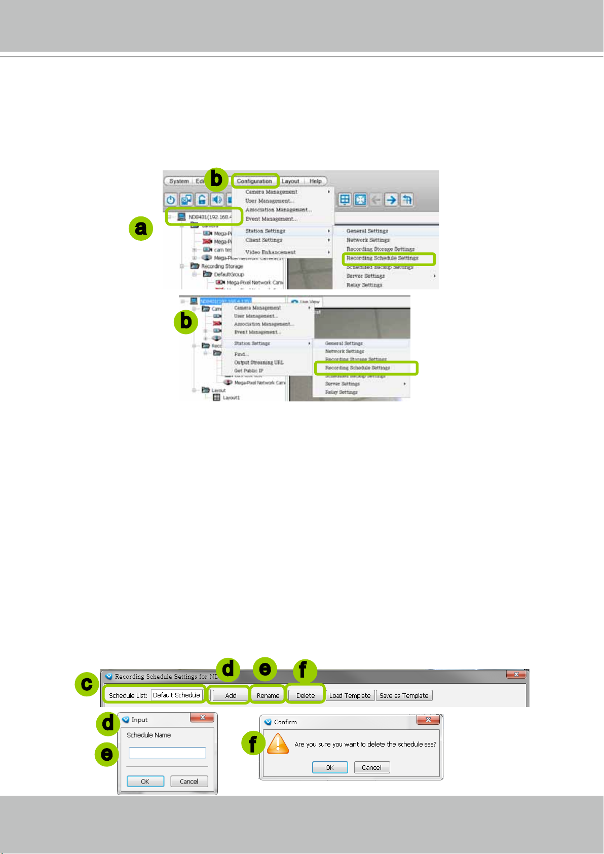
VIVOTEK
Edit Schedule List
Please follow the steps below to set up the recording schedules:
a. Select the VAST station from the hierarchical device tree.
b. Click Conguration > Station Settings > Recording Schedule Settings on the menu bar (or right-
click the station and select Station Settings > Recording Schedule Settings).
b
a
b
c. The Recording Schedule Settings window will prompt. By default, all cameras managed by the
station will be assigned to Default Schedule, Default Time Frame, and Default Camera List.
Add Schedules
d. To add a new recording schedule, click Add to enter a name in the Schedule Name dialog box for the
new schedule. Click OK to conrm the settings or Cancel to discard the settings. The new recording
schedule will be displayed on the schedule drop-down list.
Rename Schedules
e. To rename an existing schedule, select the schedule from the schedule drop-down list and click
Rename. A Schedule Name dialog will pop up for you to ll in a name for the new schedule. Click OK
to conrm the settings or Cancel to discard the settings. The new recording schedule will be displayed
on the schedule drop-down list.
Delete Schedules
f. To delete an existing schedule, select the schedule from the schedule drop-down list and click Delete.
A Remove Schedule dialog box will pop up. Click OK to conrm or Cancel to discard the settings.
d
e
f
c
d
e
90 - User's Manual
f
Page 91

VIVOTEK
Load/Save Schedule Templates
g. If you have a schedule template with time frame settings, you can upload it to facilitate the scheduling
process. Click Load Template, and a Load File dialog box will pop up. Select the template le and
click Open to load.
h. If you want to save a schedule as a template for future use, select the schedule from the schedule
drop-down list and click Save as Template. A Save File dialog box will pop up for you to save the
template le.
g
h
g
LiveClient provides two templates, Always and NoneOfceHour. You can load and edit the time
frame details.
h
User's Manual - 91
Page 92

VIVOTEK
Edit Camera List
Please follow the steps below to assign a device to a recording schedule:
a. Select a recording schedule on the schedule drop-down list.
b. By default, all devices under the station are assigned to the Default Schedule.
c. Click << to remove devices from the Default Schedule. Click -> to add devices to the Default
Schedule.
d. Click Apply to conrm or Close to discard the settings.
a
b
c
f
92 - User's Manual
Page 93
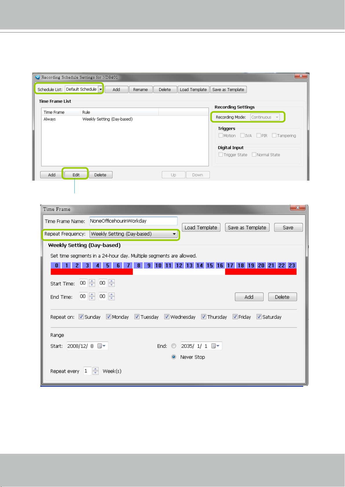
Edit Time Frame List
Default Time Frame: Weekly (Day-based), Mon.~Sun., 24-hour, continuous recording
VIVOTEK
Click Edit to open the Default Time Frame settings page as shown below.
User's Manual - 93
Page 94
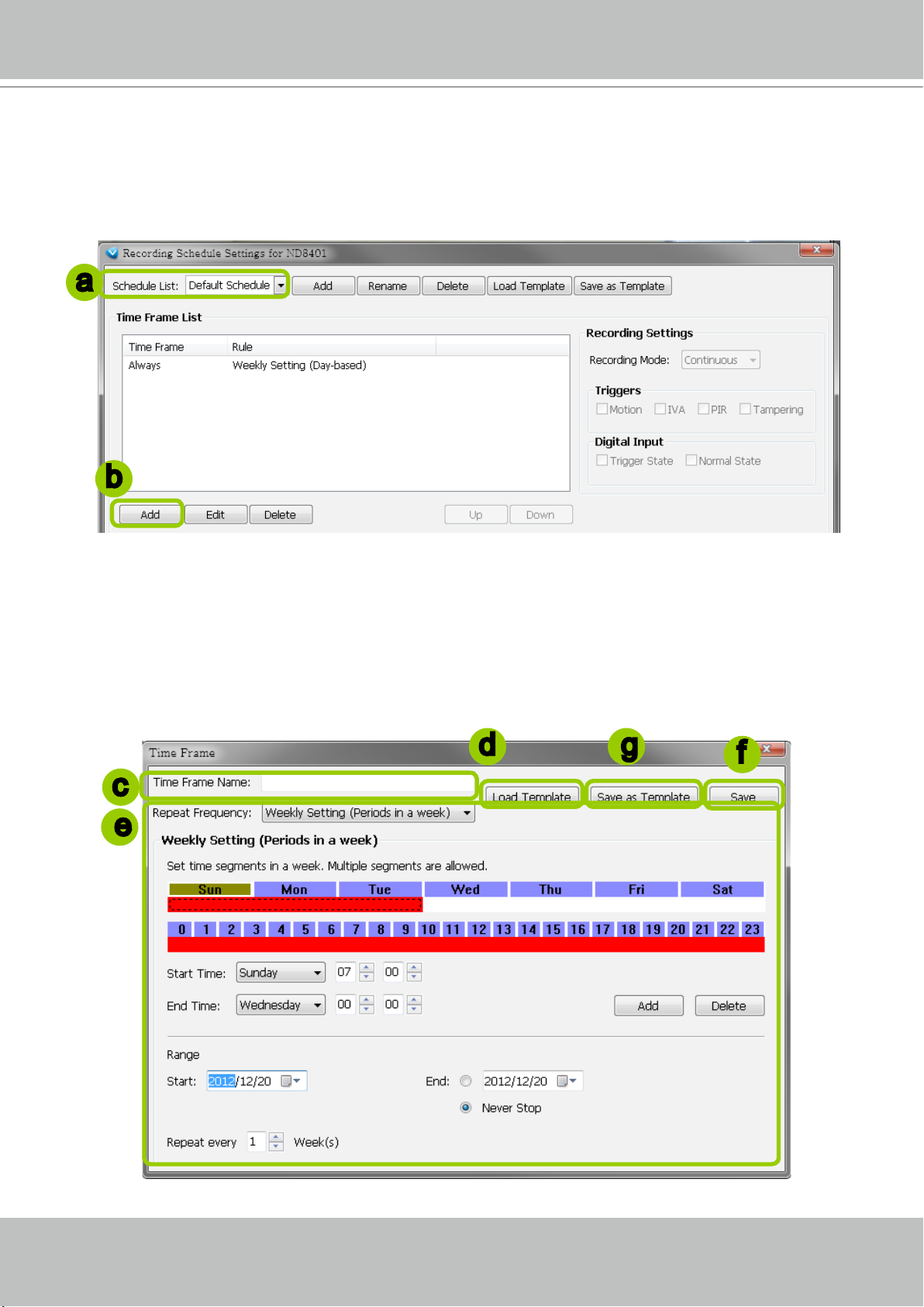
VIVOTEK
Add New Time Frames
Please follow the steps below to add new time frames to a schedule:
a. Select a recording schedule from the drop-down list.
b. Click Add to open the Time Frame Settings window.
a
b
c. Enter a name for the new time frame.
d. If you have a time-frame template, you can upload it to simplify the editing of the schedule. Click
Template and the Load File dialog box will pop up. Select the template le to load.
e. To edit the new time frame, select a Repeat Frequency from the drop-down list and edit the time
segments, applicable days, applicable period of time, and repeat time interval. For the
of each repeat frequency, please refer to The Concept of Repeat Frequency on page 96.
f. When completed, click Save to enable the settings.
g. If you want to save this time frame as a template for future use, click Save as Template. A Save le
dialog will pop up for you to save the template.
d
g
detailed settings
f
Load
c
e
94 - User's Manual
Page 95
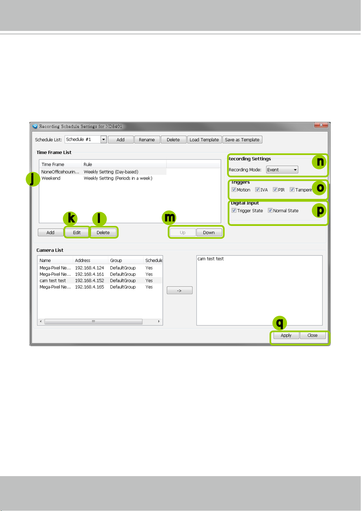
VIVOTEK
h. If you want to add additional time frames to the schedule, repeat the steps above.
i. Close the window when you nish the time frame settings.
j. Back to the Recording Schedule Settings window, the new time frame will be displayed on the Time
Frame List.
k. If you want to edit an existing time frame, select if from the Time Frame List and click Edit to set up.
l. If you want to delete an existing time frame, select if from the Time Frame List and click Delete.
m. If you want to change the priority of a time frame, select it from the Time Frame List and click Up or
Down to shift its position. The time frame on the top of the list has the highest priority.
n
j
o
p
k
l
m
q
Recording Settings
n. Select one of the following Recording Modes for the time frame:
None: No recording action.
Continuous: 24-hours continuous recording. If you want to enable Activity Adaptive Streaming,
please refer to page 88 for detailed illustration.
Event: The server will start to record only when an event is triggered. The recording time length
depends on the settings in Recording Storage Settings. The default time length is 20 seconds (10s
pre-event time plus 10s post-event time). Please refer to page 87 for more information. For more
information about event catagories, please refer to page 184 for detailed illustration.
o. Select Trigger Source(s): Motion Detection, IVA (Intelligent Video Analysis), PIR, and Tamper Detection
p. Select the status of Digital Input(s): Trigger State or Normal State
q. Click Apply to conrm the settings. Then close the window when you nish the recording schedule
settings.
User's Manual - 95
Page 96

VIVOTEK
NOTE:
The following diagrams show the frame rate variations using two different recording modes:
1. Continuous recording + Activity adaptive recording (helps save bandwidth and storage)
Bandwidth
Time
I frame ---> Full frame rate ---> I frame
Continuous Recording
2. Event recording
Bandwidth
Time
No recording data ---> Full frame rate ---> No recording data
Event Recording
The Concept of Repeat Frequency
VAST offers the following types of repeat frequency. The denition of each type is listed in the
following table:
Repeat Frequency Discription
Specify arbitrary time segments within a day,
Daily Setting
Weekly Setting (Day-based)
(Default Time Frame)
Weekly Setting (Periods in a week)
Monthly Setting (Day-based)
Yearly Setting (Day-based)
Repeat the segments every N days in the specied period of time.
Specify arbitrary time segments within a day,
Apply only on selected days of a week,
Repeat the segments every N weeks during the specied period of time.
Specify arbitrary time segments within a week,
Repeat the segments every N weeks during the specied period of time.
Specify arbitrary time segments within a day,
Apply only on selected days of a month,
Repeat the segments every N months during the specied period of time.
Specify arbitrary time segments within a day,
Apply only on selected days of a year,
Repeat the segments every N years during the specied period of time.
96 - User's Manual
Page 97

VIVOTEK
Repeat Frequency: Daily Setting
To set up daily repeat frequency, please congure the following items: Daily time segments, applicable
period of time, and repeat time interval.
Daily time segments
*You can drag the daily
Daily timeline control bar
timeline bar for more
than one time segment
per day.
Applicable period of
time
Repeat time interval
Set up daily time segments
You can specify several time segments within a day. The numbers 0~23 on the hourly timeline control
bar (the purple rectangles) represent the 24 hours in a day.
There are two ways to define time segments: one is to use the computer mouse to manipulate the
timeline control bars; the other is to fill in the precise start and end time values in the corresponding
elds.
Add time segments: Choose either step 1 or step 2 to set up
1. Use the mouse to drag the timeline bars:
a. Left-click the daily timeline control bar (the purple rectangles) and drag the mouse.
b. The corresponding time segment will also appear in the Start Time and End Time elds. Click Add,
then the red timeline bars representing new time segments will appear as shown below. You can
drag multiple time segments within a day.
In the following illustration, the yellow arrows show the dragging direction of the mouse. You can
drag from left to right or the opposite.
User's Manual - 97
Page 98

VIVOTEK
2. Fill in the precise Start Time and End Time:
a. Directly enter the value in the Start Time and End Time fields, then click Add.
b. The corresponding red timeline bar will automatically appear as shown below.
a
b
Delete time segments: Choose either step 1 or step 2 to set up
1. Use the mouse to erase the timeline bar: Right-click on an existing red timeline bar and drag the
mouse. A green timeline bar representing the deleted part of the time segment will erase the red bar as
shown below.
In the following illustration, the green arrows show the dragging direction of the mouse. You can drag it
from left to right or the opposite.
2. Use the delete button to remove the entire timeline bar:
a. Click an existing red timeline bar or left-click the daily timeline control bar (the purple rectangles)
and drag the mouse.
b. The corresponding time segment will appear in the Start Time and End Time fields.
c. Click Delete, and the selected timeline bar will disappear.
a
b
98 - User's Manual
c
Page 99

VIVOTEK
Set up applicable period of time
For repeat frequencies, you can set up the applicable date and period of time for the time frame.
a. Specify the start date and time in the Start eld. A calendar date selector will appear when you click
on the drop-down list of date. Click
calendar.
b. Specify the end date and time in the End eld if you have an end time for applying this time frame. If
you do not have a terminating time for this time frame, select Never Stop.
or to select the month, then pick a desired day in the
b
a
Click to select a year
Click to select a month from the drop-down list
Click here to move the focus to the current date
Set up repeat time interval
The repeat time intervals is "every N day(s)" as shown below. Repeat every 1 day means the time frame
would apply for every day within the period of time.
User's Manual - 99
Page 100

VIVOTEK
Repeat Frequency: Weekly Setting (Day-based)
To set up Weekly (Day-based) repeat frequency, please configure the following items: Daily time
segments, applicable days within a week, applicable period of time, and repeat time interval.
Daily timeline control bar (24h)
Set up daily time segments
Please refer to page 97 for detailed instructions.
Set up applicable days within a week
Daily Time segments
*You can drag more
than one time segment
per day.
Applicable days
within a week
Applicable period of
time
Repeat time interval
For repeat frequency--"Weekly (day based)", you can apply the time segments only on selected days of
the week.
Set up applicable period of time
Please refer to page 99 for detailed instructions.
Set up repeat time interval
The repeat time intervals is "every N week(s)" as shown below. Repeat every 1 week means the time
frame would apply for every week within the period of time.
100 - User's Manual
 Loading...