

Page 1
iViewer
Monitoring Application for iPad , iPod ,and iPhone
R
R
R
Rev. 2.0
Page 2
2
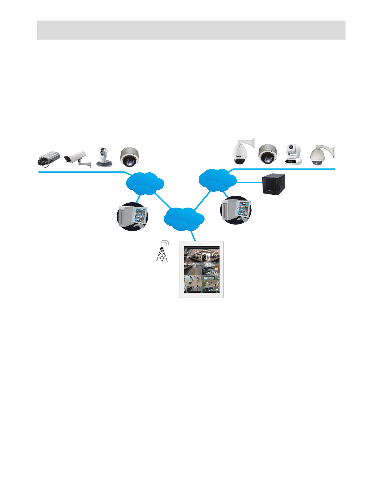
1-2. An established VAST, ST7501, or VIVOTEK's NVR deployment consisting of multiple
network cameras, where the VAST or ST7501 servers can be accessed via a public
IP or DNS service. The corresponding VAST and ST7501 software must be of a
revision number 1.5.2.8 or later.
I. Requirements
VAST
Server Station
ST7501
Server Station
iViewer
Wi Fi
WAN
LAN
port: 3454
port: 3454
NVR
LAN
1-3. Network cameras have already been configured via VAST, ST7501 software, or
VIVOTEK's NVR station, namely, "inserted" into the managed list of cameras of the
above software.
1-1. iViewer rev. 2.0 supports iOS 6.0. You should upgrade your operating system on the
following devices:
iPhone 4S, iPhone 4, iPhone 3GS, iPad (3rd generation), iPad 2, and iPod touch (4th
generation).
Page 3
3
Wi-Fi Access Point
LAN
Network Cameras
iViewer
port: 80
port: 80
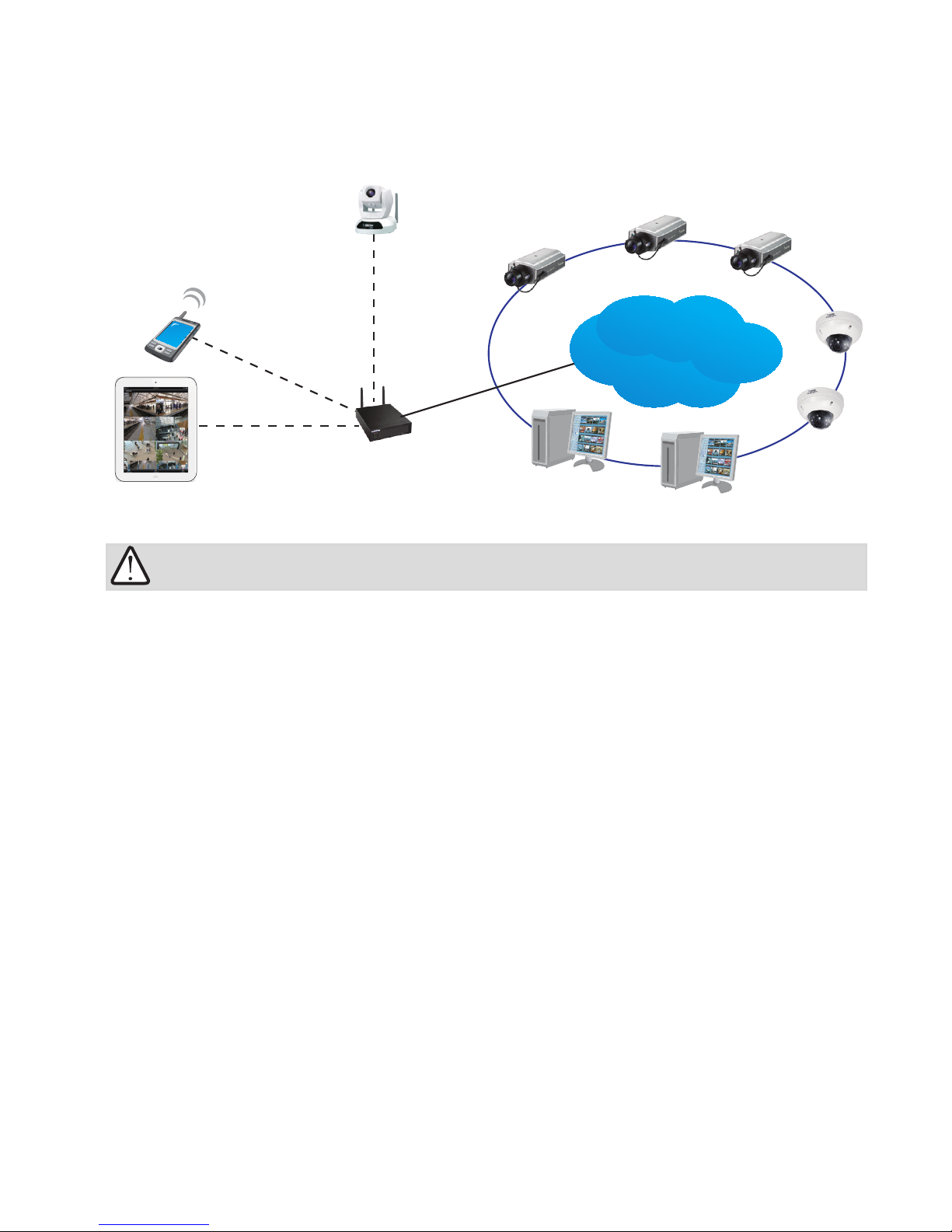
1-4. The iViewer rev. 1.3 and above supports direct connections with network cameras
when their IPs are known to the user. However, video playback can only take place
if the past videos were recorded on the VAST/ST server or NVR station. The iViewer
currently does not support video playback from the cameras' SD card.
If you connect via Internet to a VAST/ST server, NVR station, or cameras behind a
rewall or router,
• When connecting to a VAST/ST server or NVR station-
If a VAST/ST server or NVR station is located behind a firewall or router,
congure port forwarding or "bypass tunnel," by mapping TCP port "3454" (for
access to VAST) on the router to your VAST/ST server or NVR station. Enter
the server's public IP and port "3454" on the iViewer conguration pane.
• When connecting to individual cameras -
If an individual camera is located behind a firewall or router, configure port
forwarding or "bypass tunnel," by mapping TCP port "80" (camera's default for
HTTP). Enter the camera's public IP and port "80" on the iViewer conguration
pane.
Please consult your network administrator or the documentation that came with
your rewall or broadband router.
IMPORTANT:
Page 4
4
• Below are typical TCP ports for access to individual network cameras
Network General settings:
HTTPS = 443
FTP = 21
Streaming:
HTTP = 80
Secondary HTTP = 8080
RTSP = 554
RTP for video = 5556
RTCP for video = 5557
RTP for audio = 5558
• By default, the smallest resolution stream will be selected for display. In most
cases, it is the no. 3 for 3 stream models, or no. 3 for 4 stream models. If you
change the video stream on a "full-view" view cell, the stream selection will
automatically be saved into the layout conguration.
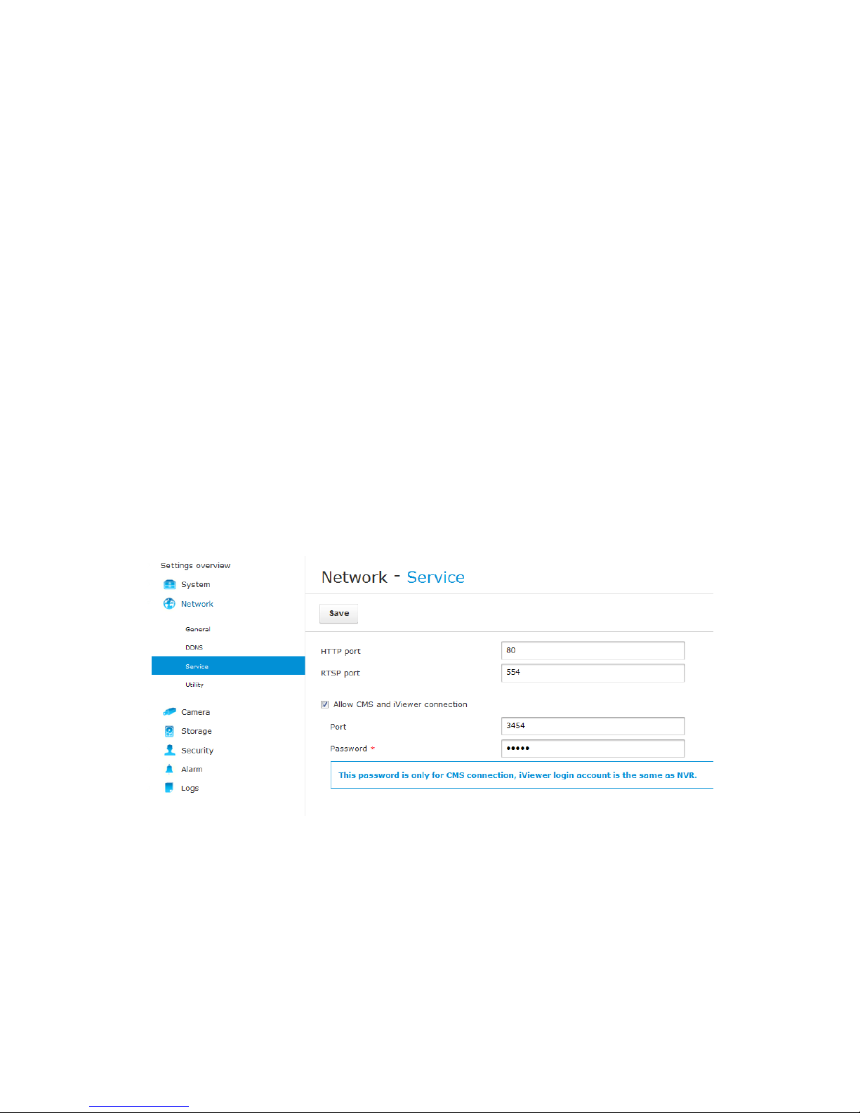
• To establish a connection with the NR8401, you need to enable the connection
on a web console via Network > Service. Select the "Allow CMS and iViewer
connection" checkbox, and enter the same password as that you use for login
to NVR console.
Page 5
5
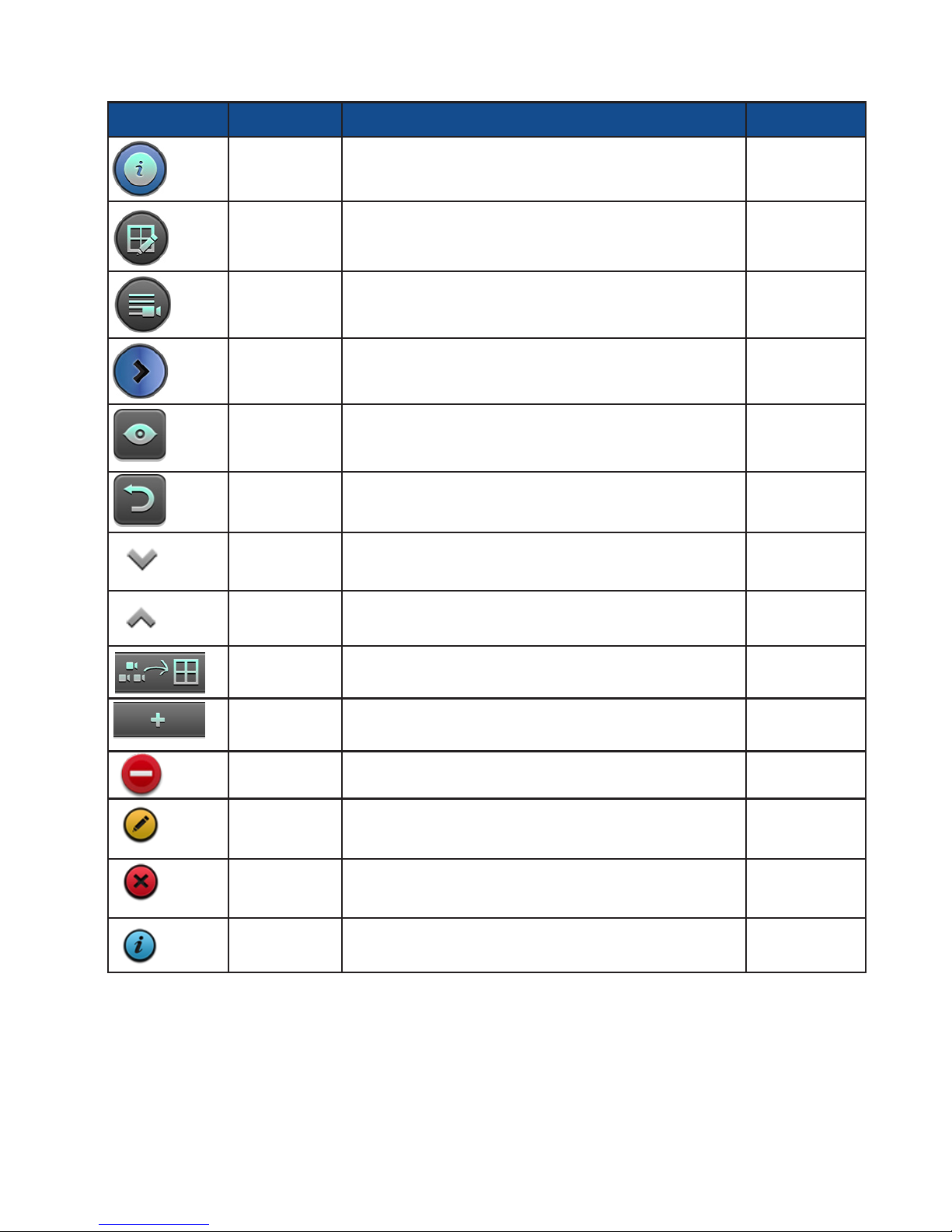
Knowing Buttons in iViewer
Icon Name Function Location
Conguration
1. Displays the software revision.
2. Provides a link to technical support.
Live
Layout
Opens the Layout page
Live
Media Source
Opens the Media Source page for adding cameras to
the current conguration.
Live
Device list
Displays the Camera and Server device list for adding
cameras.
Live
Back to Live
view
Returns to Live view when in the Playback mode
Playback
Return
Returns to previous page.
Conguration
pages
Expand the
list
Expands the device list
Layout >
Device
Hide the list
Retrieves the device list
Layout >
Device
Add All
Adds all cameras in queue to layout
Layout >
Device
Add
Click to add devices (single cameras, VAST server, or
video server)
Media Source
page
Remove
Remove a camera from a view cell
Layout >
Device
Edit device
Edits device information, such as address, access
port, or credentials. .
Media Source
page
Remove
device
Removes an existing device.
Media Source
page
Device
Information
This icon displays while editing device information
Media Source
page
Page 6
6
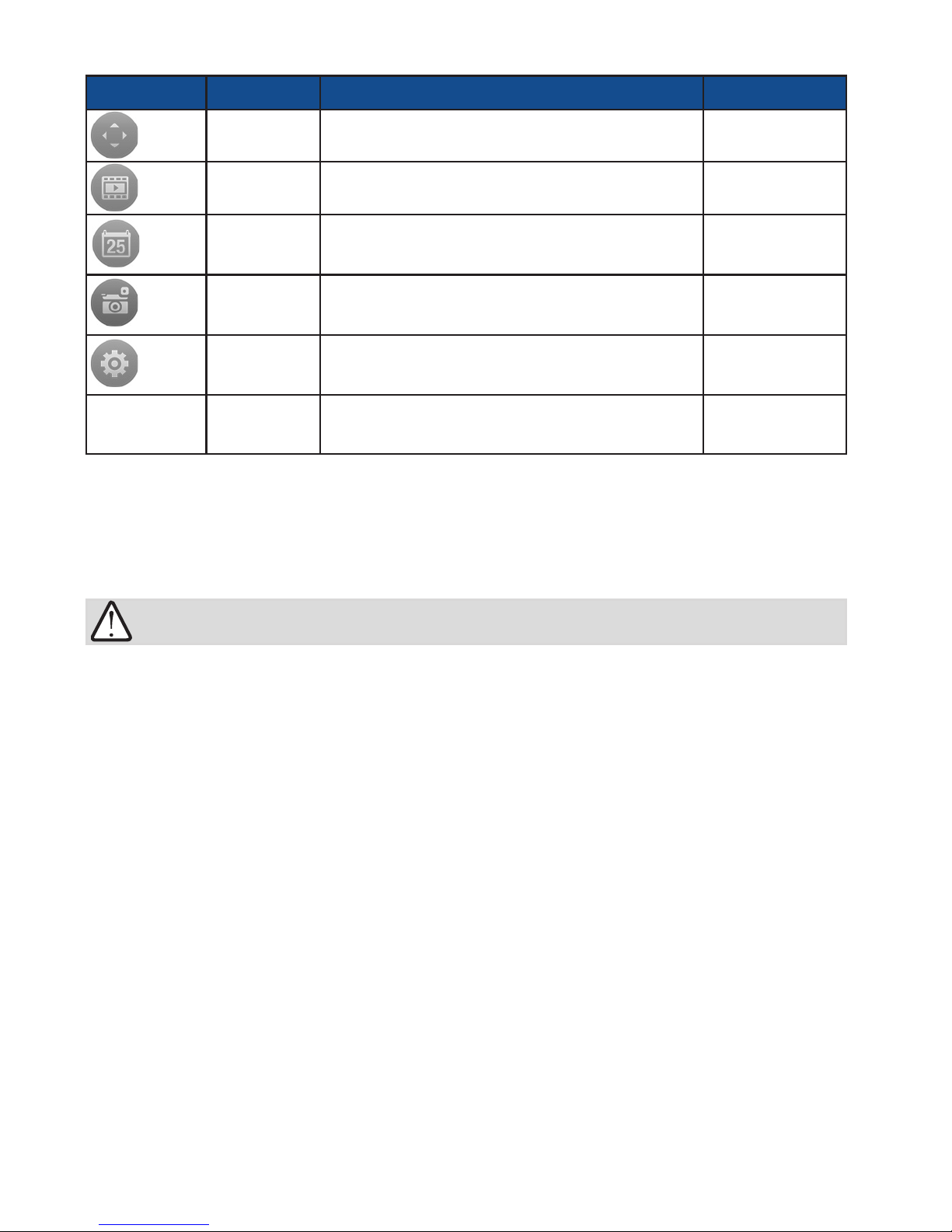
Icon Name Function Location
PTZ
Enters the PTZ mode
Enlarged view cell
Playback
Opens the Playback roller selector
Enlarged view cell
Playback
Time
This icon is shown when playing the past
recording.
Enlarged view cell
Snapshot
Takes a snapshot of the current screen
Enlarged view cell
Conguration
Enters the camera conguration screen
Enlarged view cell
Since wireless connection and video streaming consume considerable power, you should
leave the iViewer when you are not watching the live view. Press the Home button to leave
the iViewer.
IMPORTANT:
Page 7
7
II. Getting Started and Basic Operation
Starting Up
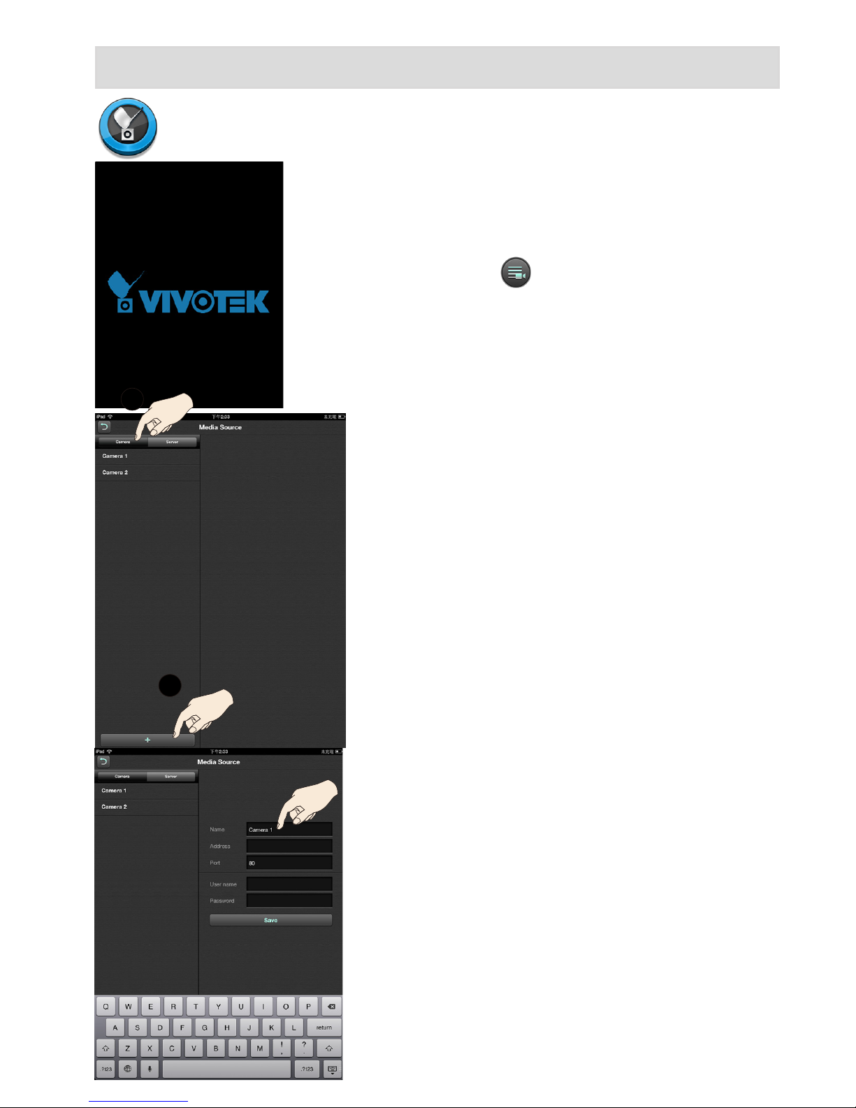
2-1. iViewer is aquired through the App Store,
and is started by a double tap on its icon.
2-2. You will enter the Live view window.
On initial setup, you should tap the Media
Source button on the lower center of
the screen to enlist cameras or servers.
1
2
2-3. You will enter the Media Source window.
2-3-1.
If you are adding individual cameras:
Tap on the Camera tab. You may then single
tap in each entry field including, Camera
name, Address, Port, User name, and
Password, and enter necessary information.
By default, Stream #3 is selected for its lower
resolution and frame rate, e.g., 176x144 and
5fps, and is recommended.
When done, click the Save button to recruit
the camera, and repeat the process to add
more cameras.
A keypad will prompt whenever you tap on an
entry eld.
The cameras enlisted will be listed on the
left panel. It is recommended to create a
comprehensive camera name for each
camera for easy of identication.
Limitation on entry:
Camera/Server name: 16 (iPhone), 32(iPad)
numeric and alphabetic characters.
Camera/Server address: 128
Camera/Server port: 5 numeric
Camera/Server Password: 64
Page 8
8
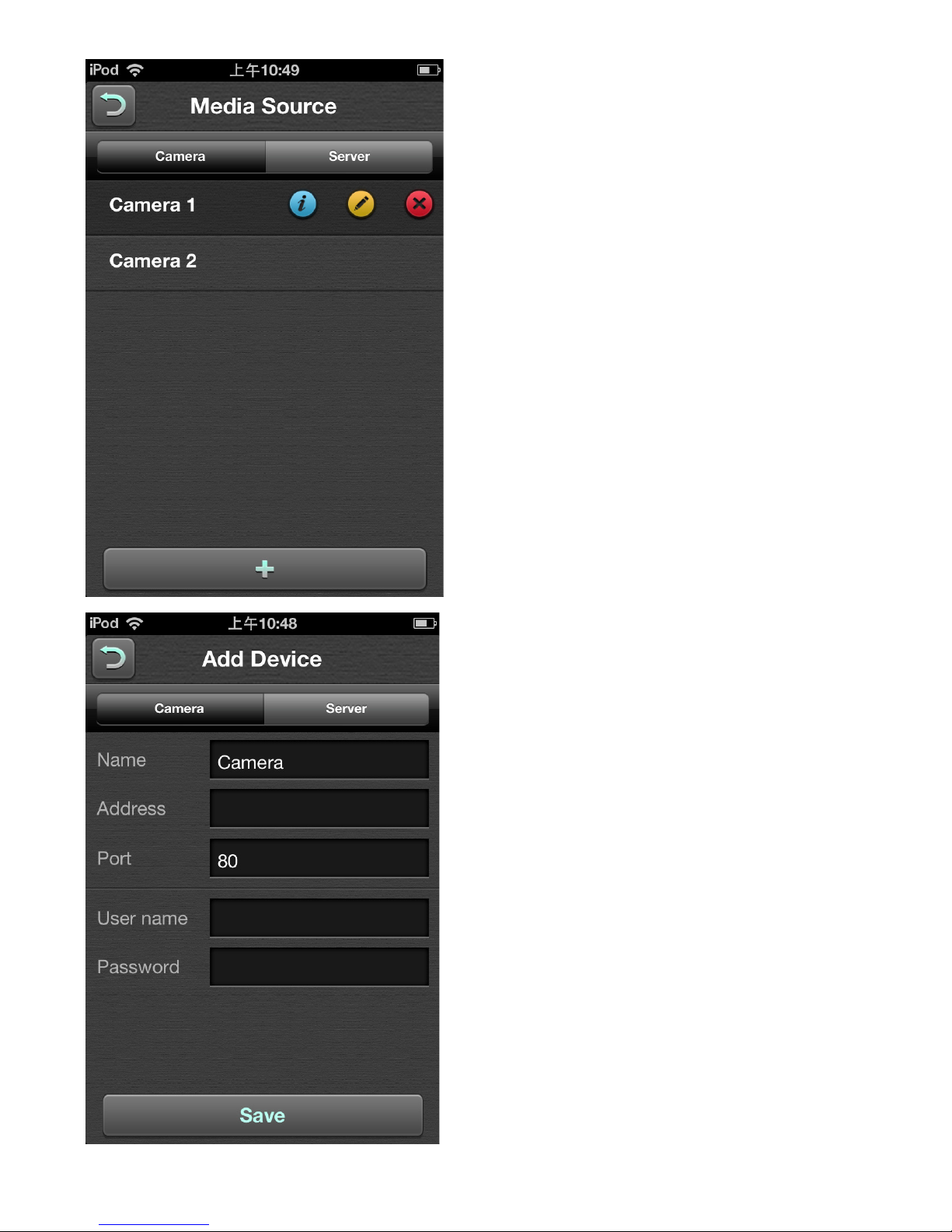
Due to the screen size, on a iPhone or iPod,
the configuration options are listed on a
succeeding page.
Page 9
9
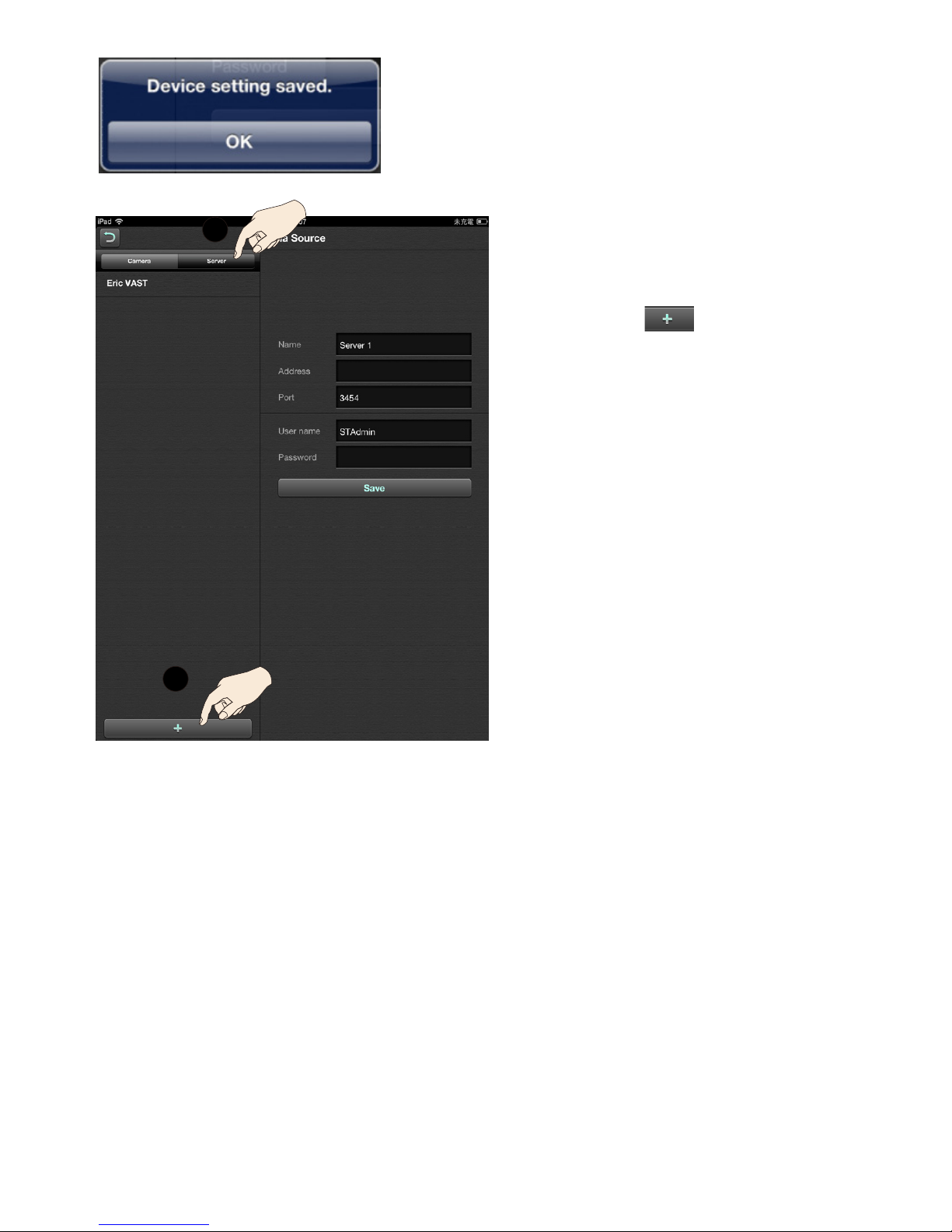
The iViewer will try the initial connection, and when
successful, a message will prompt as shown.
Cameras thus configured will be auto matically
added to the view cells on the Layout screen.
2-3-2.
If you are adding a VAST/ST server or
NVR station:
Tap on the Server tab.
Tap on the Add button.
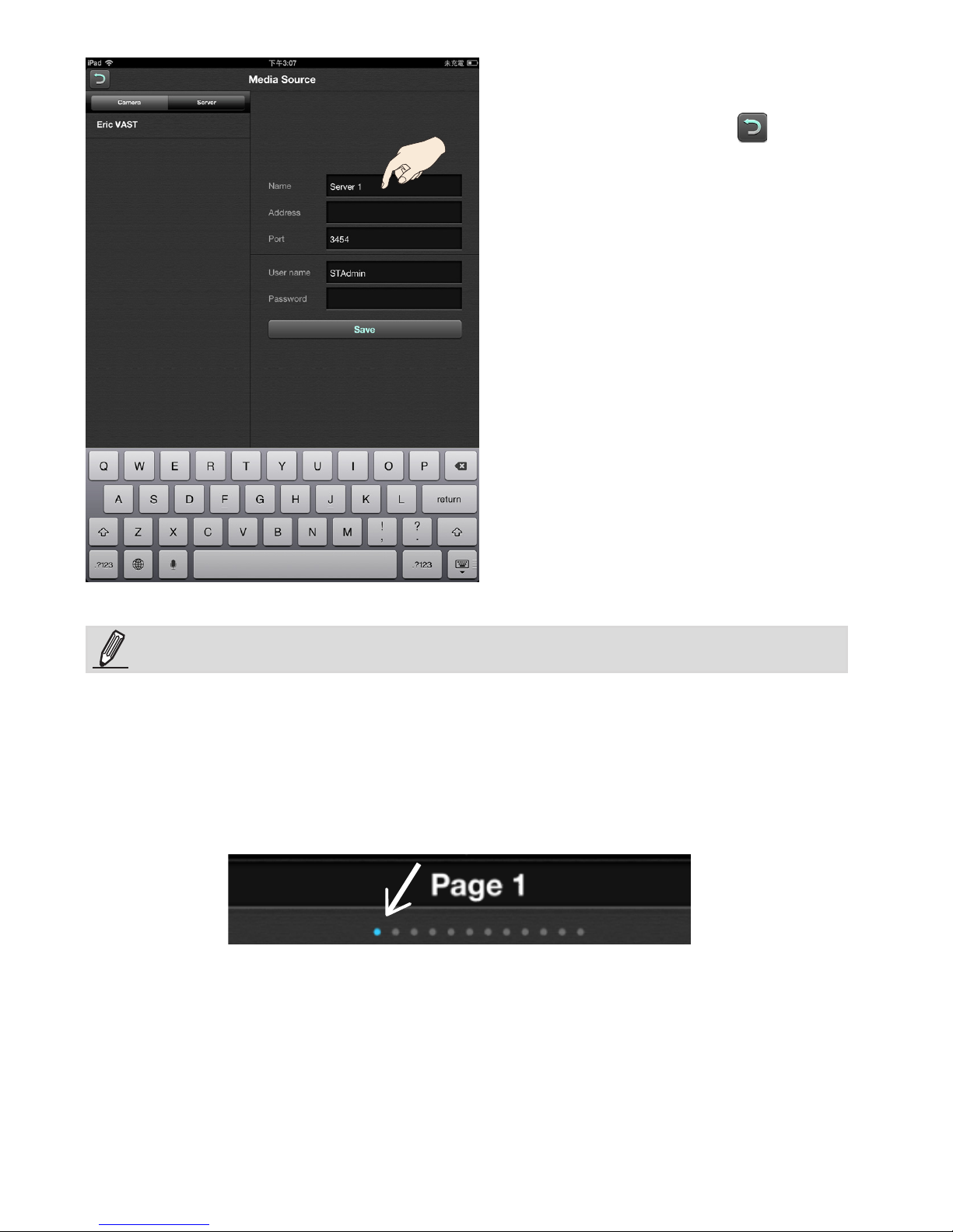
You may then single tap in each entry
eld including, Server name, Address,
Port, User name, and Password. Enter
login information for access to a VAST,
ST-7501 server, or an NVR station.
When done, click the Save button to
recruit the server, and repeat the process
to add more.
A keypad will prompt whenever you tap
on an entry eld.
All cameras managed by the server will
be available in the Server queue. You
may then place them onto the iViewer
Layout pages.
1
2
Page 10
10
2-3-3.
After you configured all cameras and
servers, tap on the Return button to
turn to the Live window.
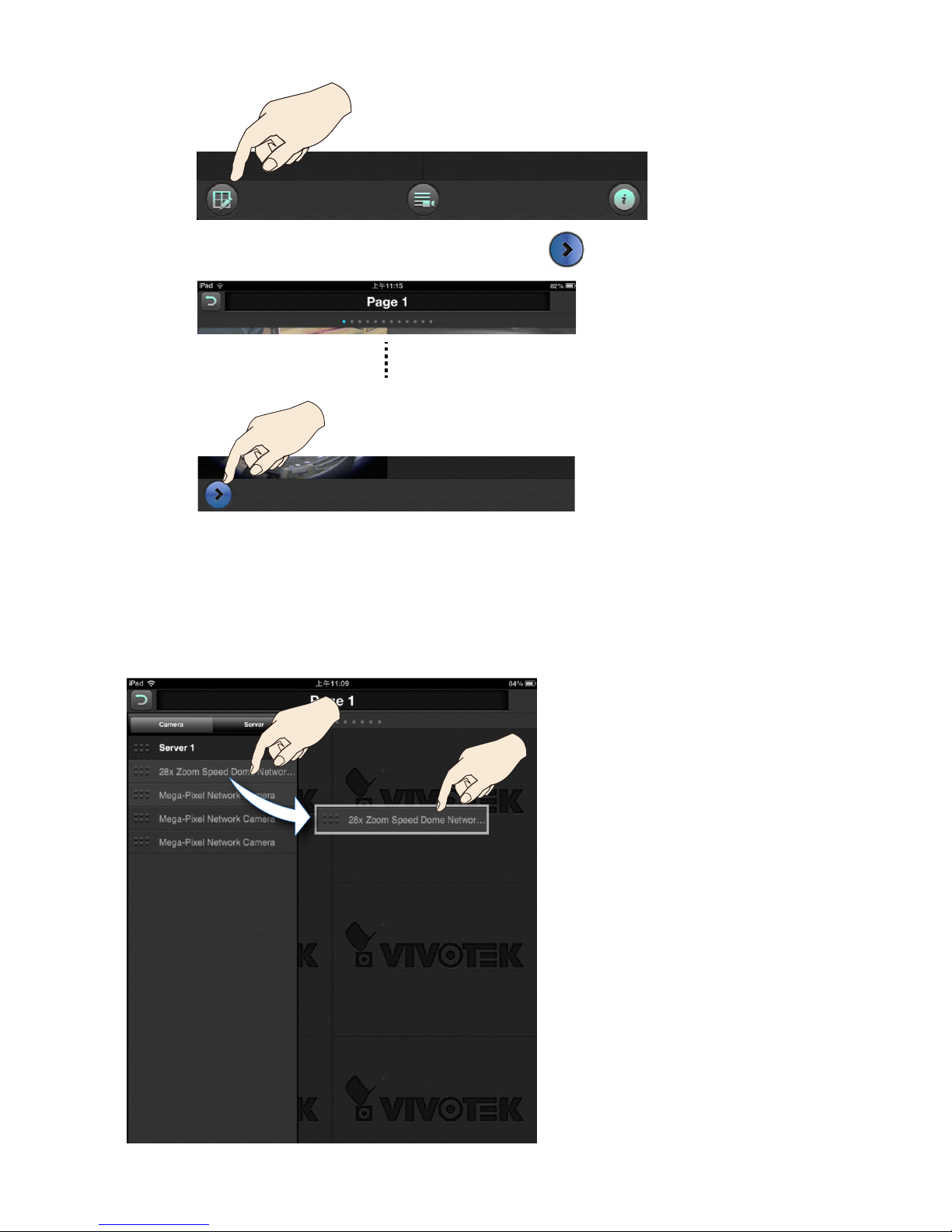
When inserting cameras, ensure that you start from the rst screen. There are dots
above the Dock showing the number of available live view screens and your current
position. There are 12 screens available, and each can contain 6 camera view cells.
iViewer provides view cells to contain video feeds from up to 72 cameras.
You may mistakenly move to a different screen by swiping your nger tip across the
screen.
NOTE:
Page 11
11
2-4-1.
When in the Layout page, tap on the Device list button.
0.5 sec
2-4-2.
All individual cameras or cameras under a VAST or NVR server will be listed. You can
place your nger tip on one camera for 0.5 second until it becomes aoat, and then
drag it to a view cell you prefer.
Video servers and individual cameras will be listed in the Camera pane.
2-4. Enter the Layout page by a single tap.
Page 12
12
0.5 sec
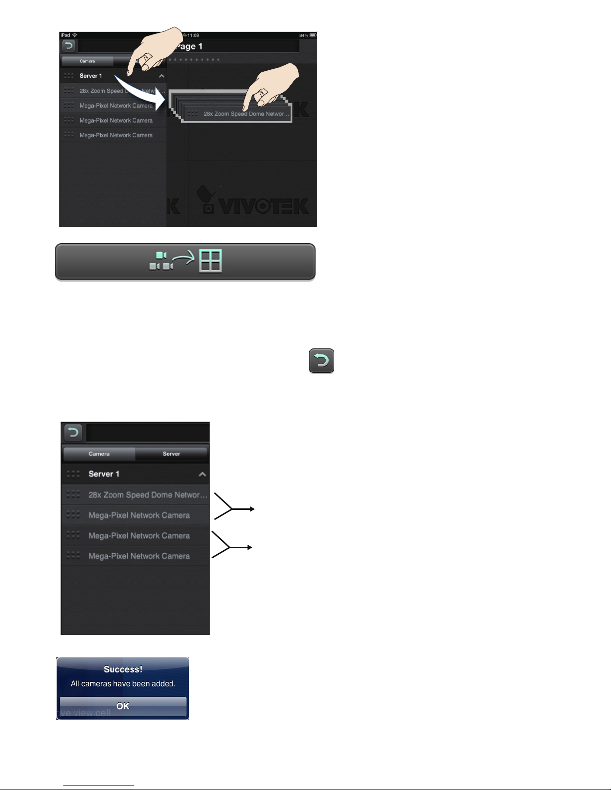
You can also select the entire server
by placing your finger on the Server
entry. All cameras under the server will
be placed into view cells.
You can also use the Select all button
to automatically place all cameras into
view cells. Cameras will be inserted
following the alphabetical order.
Note that you do not need to save the layout. When done with
layout, tap the Return button on the upper left of the screen
to return to the Live window.
Not inserted yet.
Inserted.
The cameras that have already been inserted
will be placed at a lower position on the list, while
those that have not been inserted will be displayed
in a lighter color, and at a higher position on the
list.
This is the message when all cameras in queue
have been successfully added.
Page 13
13
• You can not register cameras of duplicate names onto the layout page.
• You can not modify the connection parameters of connected cameras. If parameters
have been changed, e.g., IP address, you need to remove, and then insert the
camera again.
NOTE:
2-5. Double tap on a camera view cell opens a full view window. Double tap on a Full
View window returns you to the Live window.
Four functional buttons are available on the screen:
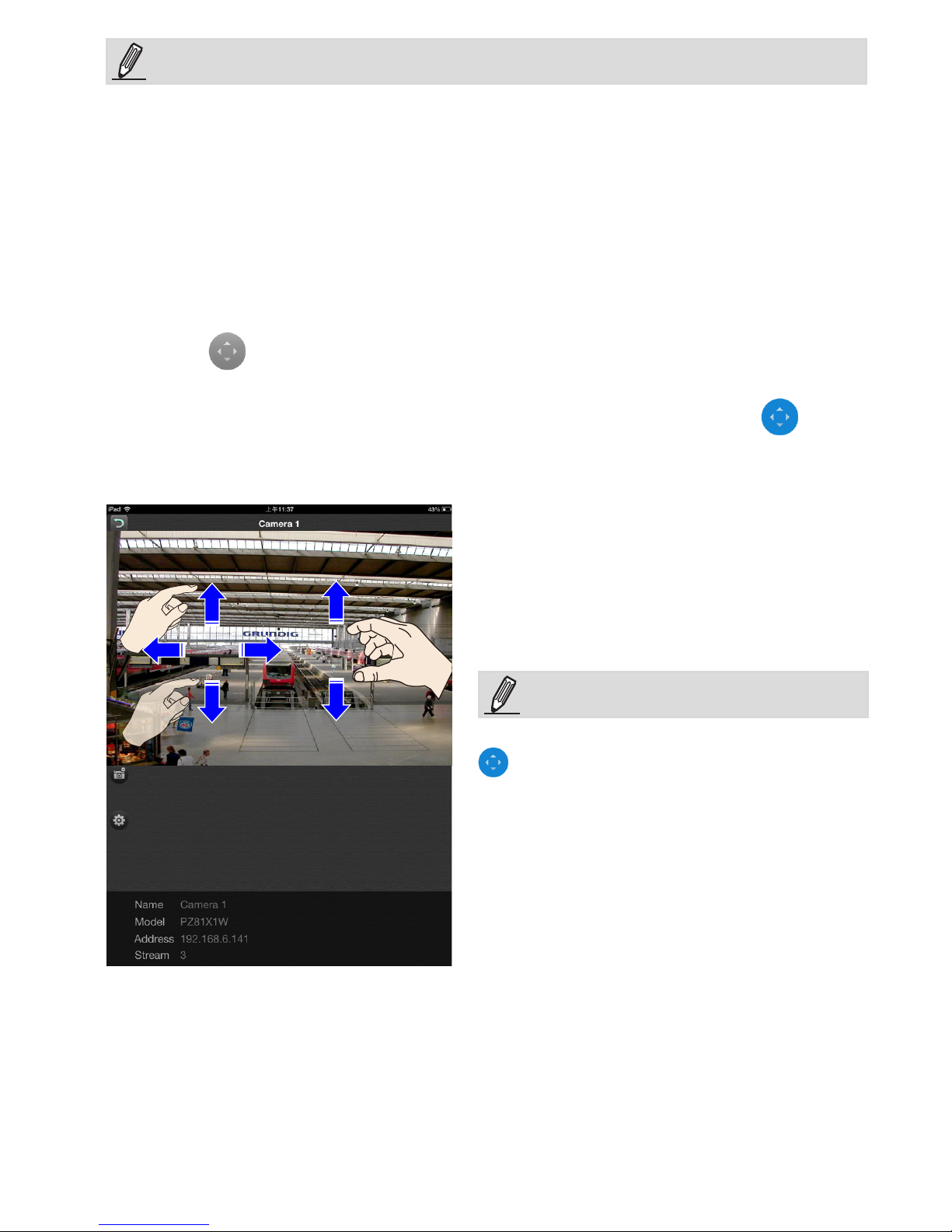
2-5-1. PTZ: provides zoom, pan and tilt control for cameras that come with PTZ
mechanisms, such as a speed dome camera.
Tap on the button to enable the PTZ functions. The button will turn blue.
Tap on the button again to diable the PTZ functions.
For fisheye cameras, use the PTZ button
to enable PTZ control in a Regional or
Panoramic view.
NOTE:
Zoom In
Pan or tilt
Use your ngers to exert PTZ control to move
to a different field of view, or zoom in/out on
a view. Swipe your finger to the opposite
direction of your target to move to it.
Page 14
14
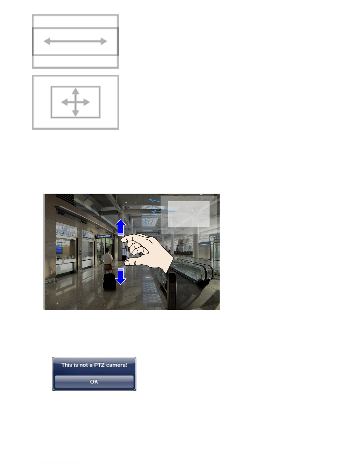
When in a sheye Panoramic view, swipe to the left
or to the right to change the eld of view.
When in a fisheye Regional view, zoom in, place
your finger tip on the screen, and then drag your
nger across the screen in any direction to change
the eld of view.
If using a camera that does not have the PTZ mechanisms, tapping the button will bring up
the following message.
PiP (Picture in Picture): provides PiP control for cameras that do not have the PTZ
mechanisms. (such as a eld of view from a xed lens camera). Once zoomed in,
you can move the focus by nger-swiping in all directions, zoom in/out to explore the
regions within a wide angle of view. You can zoom in on a view cell without using the
PTZ button.
Full view
Current field of view
You need to zoom out to the
full extent before you can
swipe the screen to move
to the live view of another
camera.
Page 15
15
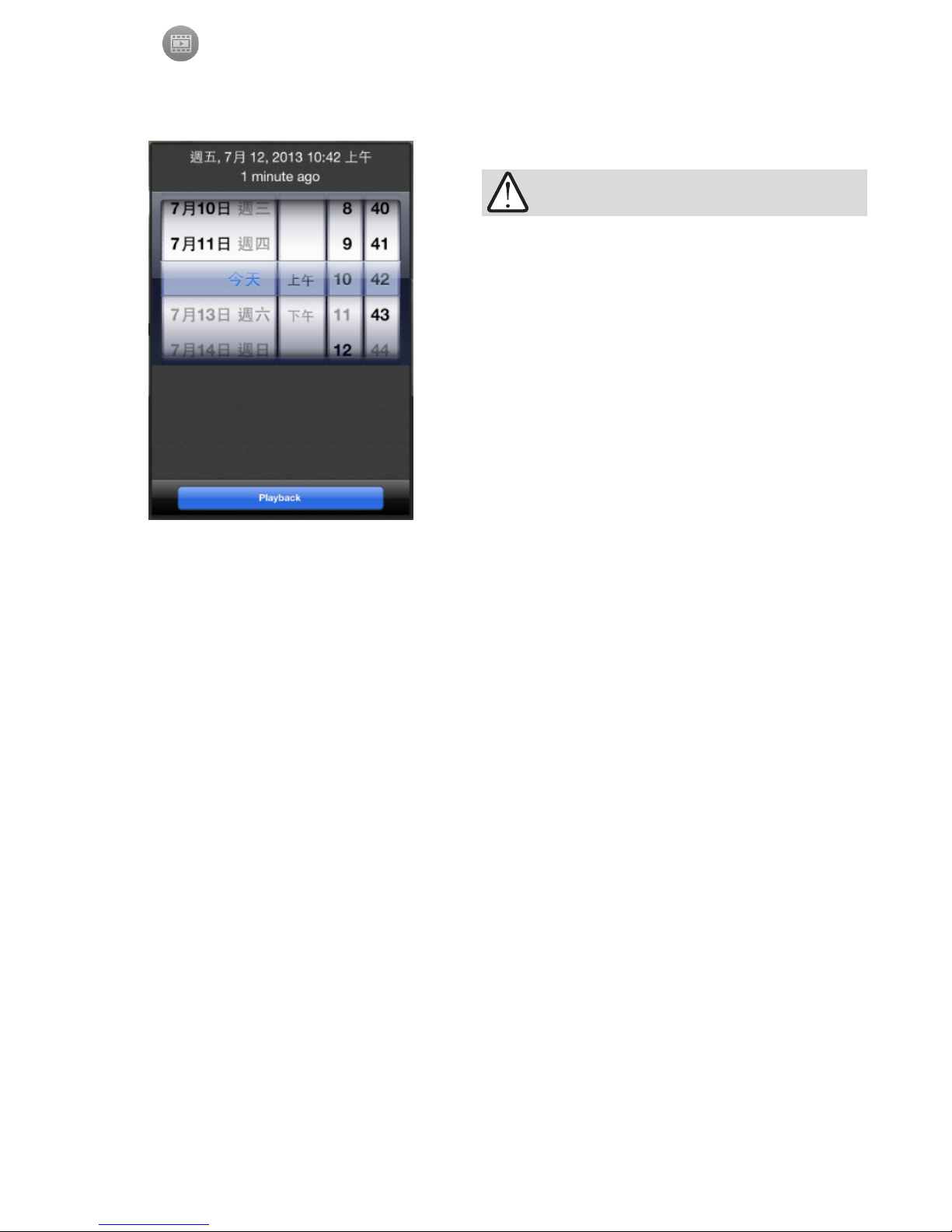
2-5-2. Playback: searches and plays recorded video footages on a VAST, ST7501
server, or an NVR station. Use the time roller to select the time when the recording
took place. Click on the Playback button to retrieve past videos.
The presumption is that you already know a
recorded video does exist for a specic point
in time, and by a specic camera.
IMPORTANT:
Page 16
16
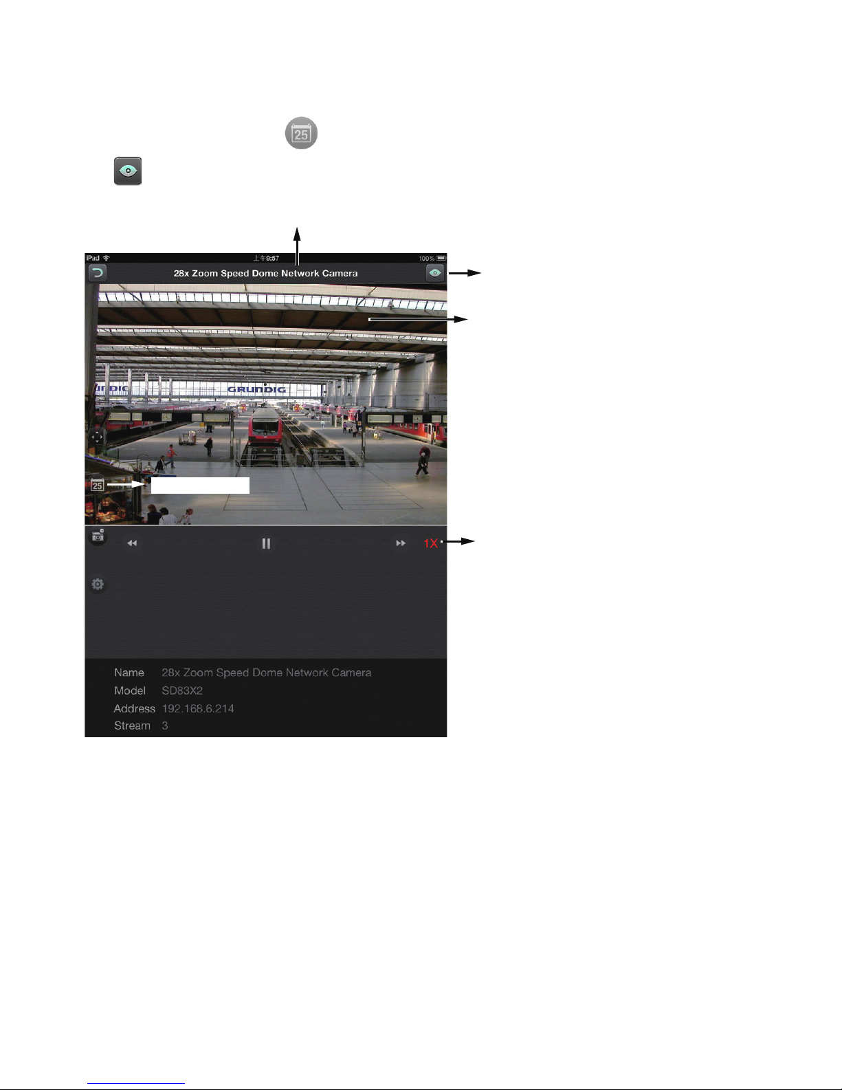
2013/07/15 17:00:04 Recorded time of
current playback
Return to Live
Control buttons
Camera name
Playback time
The Playback window provides control over the selected video footage. You can tap on
the forward and backward buttons several times to increase or decrease the playback
speed.
Tap on the Playback time button to return to the Time Selection roller. Tap on the
Live button to return to the Live View window.
Note the following when using the Playback function:
1. You can also use your fingers to zoom in/out on the Playback screen. See the
description for PiP on the previous page.
2. For a sheye camera, you can select a different display mode during the playback, such
as 1R or 1P.
3. The Snapshot function also applies in the Playback window.
Page 17
17
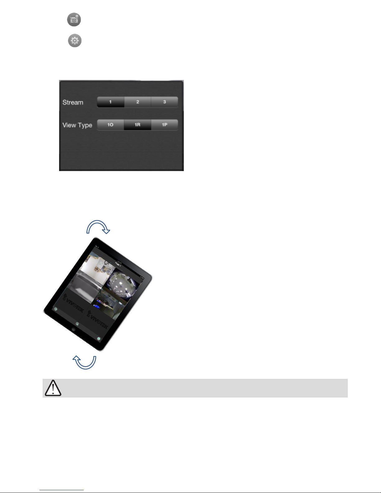
Rotate your iPad to view a live video in a portrait
or landscape orientation. The video rotates
accordingly for both multi- and single-cell
displays.
1. The PTZ, Playback, Snapshot, and Conguration options discussed above only appear
in a Full View window.
2. The PTZ function takes effect only if your cameras come with PTZ mechnical design,
such as a speed dome camera.
3. The PiP function allows users to zoom in on an existing video feed and move along to
different areas covered by the video feed.
IMPORTANT:
2-5-3. Snapshot: saves the current view as a jpeg.
2-5-4. Camera Conguration: Click this button to change the video stream for the
current view cell. If using a sheye camera, you can change the display mode into
the 1R (Regional) or 1P (Panoramic) mode. Note that the rest of sheye's display
modes are currently not supported.
View Type:
1O: The orignal circular view. Note that
you can not exert the PiP function in
this mode.
1R: The Regional view. You can perform
PTZ functions in this mode using
finger moves to move to a different
view area, or zoom in/out on a view
area.
1P: The Panoramic view displays a long
stripe of an all round view. You can
rotate the image horizontally using
nger swipes.
If you change the video stream for the full
view window here, that only takes effect
for the full view window. The smaller view
cells on the Layout page will still display
the smallest-resolution streams.
Page 18
18
III. Other Functions
3-1. Editing an Existing Server or Cameras
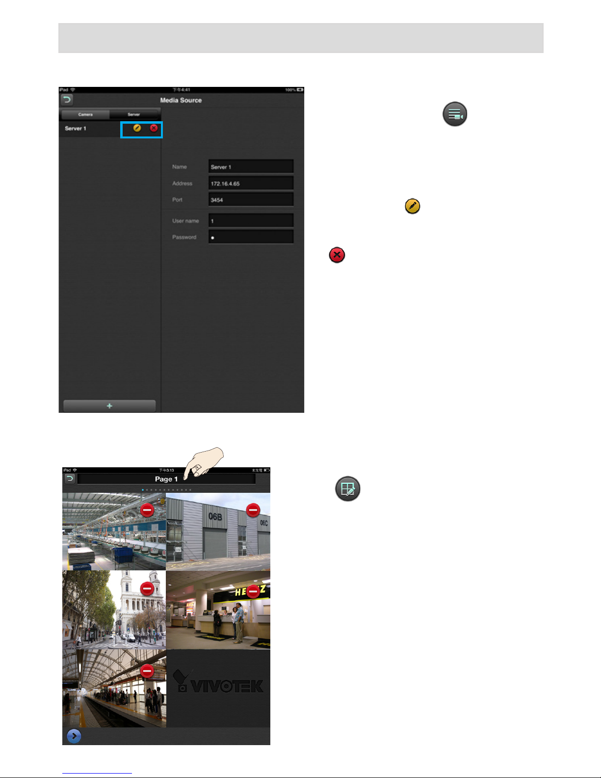
Enter the Media Source page by tapping
on the Media Source button.
Tap on the Server tab, the Conguration
page for existing servers will display.
Tap the Edit button to change the
existing information or use the Delete
button to remove a server.
If you remove a server, all cameras
managed by it will disappear from the
Live view window.
Note that the address and port number
are not congurable. If the address and
port number have changed for some
reasons, you should remove the camera/
server and then enlist them again.
Use the button to enter the Layout page.
Double tap on the page title. A virtual keypad
will prompt. You can then change the name of
the layout page, e.g., from Page 1 to Lobby 1.
When done, close the virtual keypad. Repeat
the process to rename other layout pages.
x 2
3-2. Renaming the Layout Page
Page 19
19
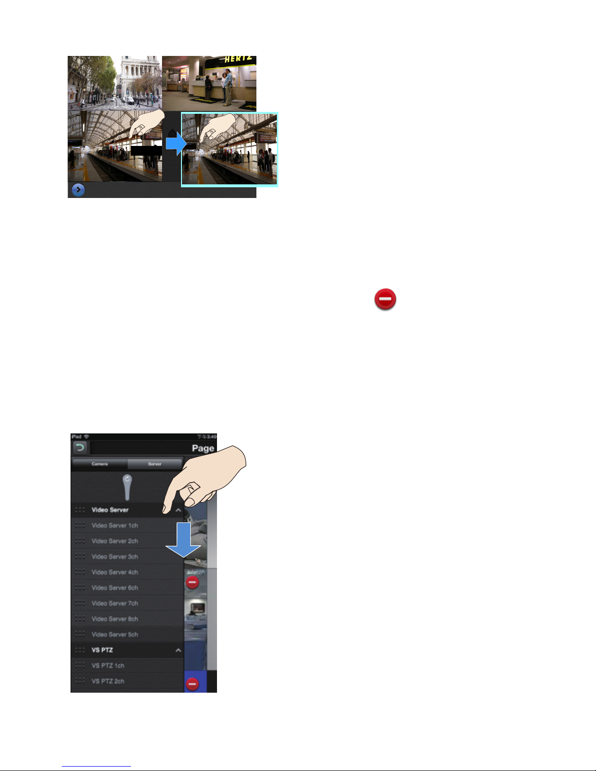
On the Layout page. Place your finger on a
view cell for 0.5 second. When it becomes
afloat, drag it across the screen to a new
location. You can also drag a view cell across
layout pages by dragging it to the border of
your current layout, and staying there for
one second. You can then drag it to the
neighboring page.
If the target view cell is already populated by
another camera, dragging a view cell to it will
swap their positions.
0.5 sec
3-3. Re-arranging the View Cells
Note that the snapshot images on view cells are not constantly updated. They are updated
only once a day.
If you remove a camera from a view cell uing the Delete button, the camera will still
be listed on the device pane.
If you enlist new individual cameras to your device list, they will be automatically added
to the unoccupied view cells. However, if you enlist new cameras to a VAST server, those
cameras will not be added to the view cells.
If changes occurred to an existing server, e.g., adding
or removing cameras, you can pull down the device
entry for the system to reload the device data. The
software will then retry the connection and refresh all
information.
If problems still remain unsolved, you may remove
the device and insert it again. This may occur if you
upgraded your software from ealier iViewer.
Page 20

20
iPad®, iPod®, and iPhone® are trademarks of Apple Inc., registered in the U.S. and other
countries.
Credit Notice
Below are the limitations of the current release of software:
1. The Two Way Audio communication with cameras is currently not supported.
2. I/O triggers and notication from the cameras is not supported.
3. The iViewer does not run in the background when users leave the current session.
4. iViewer does not support login with a preset account and password.
5. iViewer does not support conguration backup and restore functions.
6. iViewer does not support video recording to iPhone and iPad.
7. iViewer does not support playback of videos recorded on cameras' SD cards.
NOTE:
 Loading...