

Page 1
Page 2
EN - 1
English
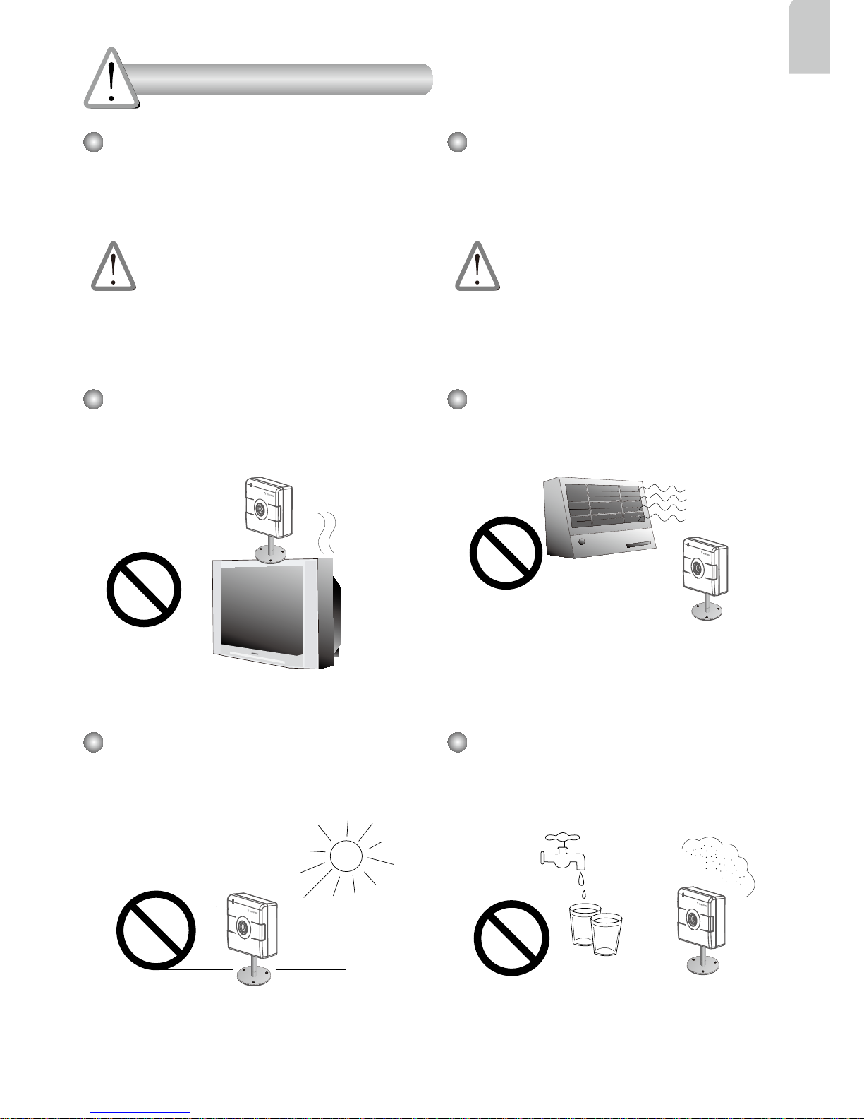
Power off the Network Camera as
soon as smoke or unusual odors are
detected.
Contact your distributor in the event of
occurrence.
Keep the Network Camera away
from water. If the Network Camera
becomes wet, power off immediately.
Do not place the Network Camera
around heat sources, such as a
television or oven.
Refer to your user’s manual for the
operating temperature.
Keep the Network Camera away from
direct sunlight.
Do not place the Network Camera in
high humidity environments.
Contact your distributor in the event of
occurrence.
Warning Before Installation
Page 3
EN - 2
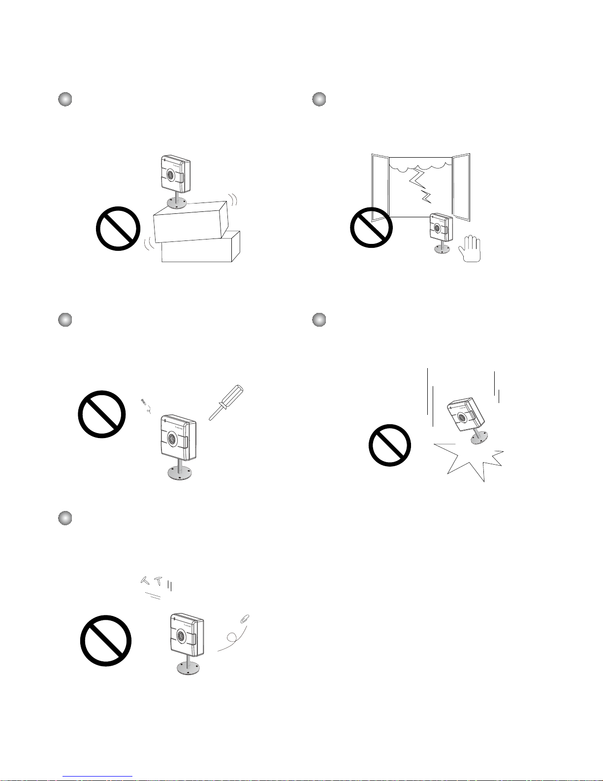
Do not place the Network Camera on
unsteady surfaces.
Do not touch the Network Camera
during a lightning storm.
Do not disassemble the Network
Camera.
Do not drop the Network Camera.
Do not insert sharp or tiny objects
into the Network Camera.
Page 4
EN - 3
English
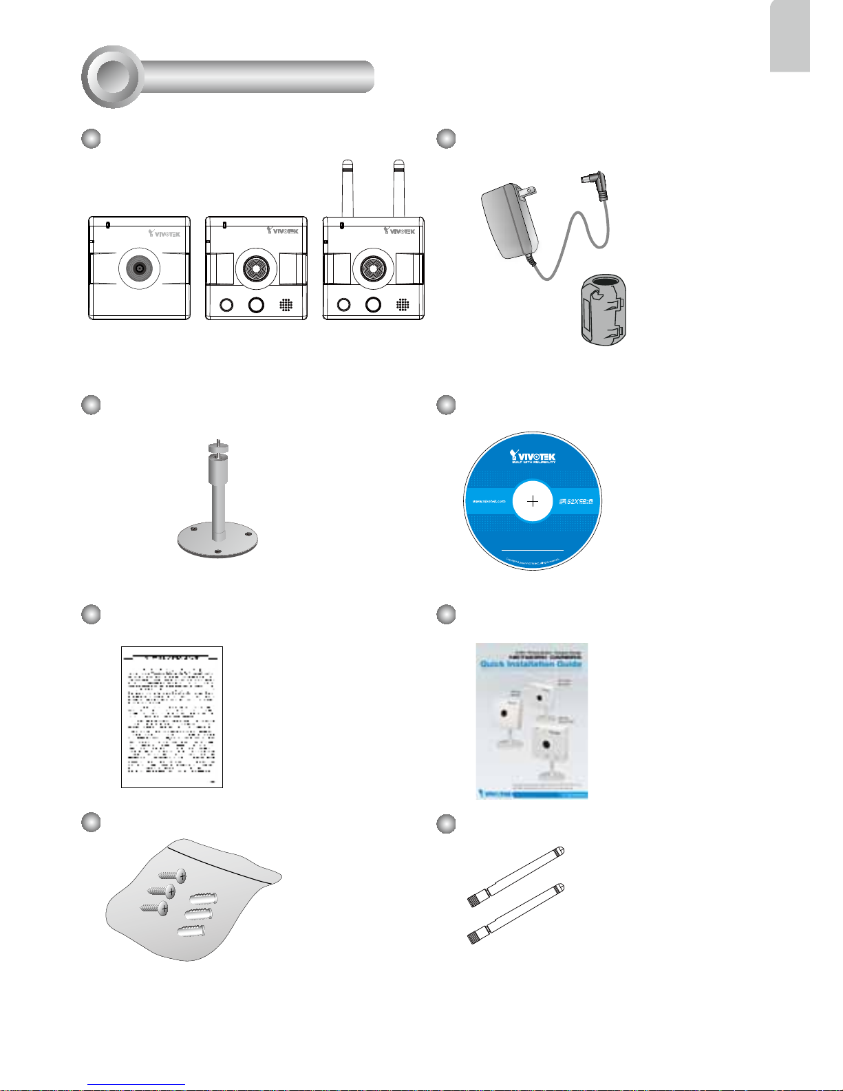
Camera Stand
IP8132
Warranty Card
Screws
Quick Installation Guide
Power Adaptor (+5V, 2A) & Ferrite
Core
Package Contents
1
Software CD
5
1
0
0
0
0
2
0
2
G
IP8133
Antennas (IP8133W)
IP8133W
Page 5
EN - 4
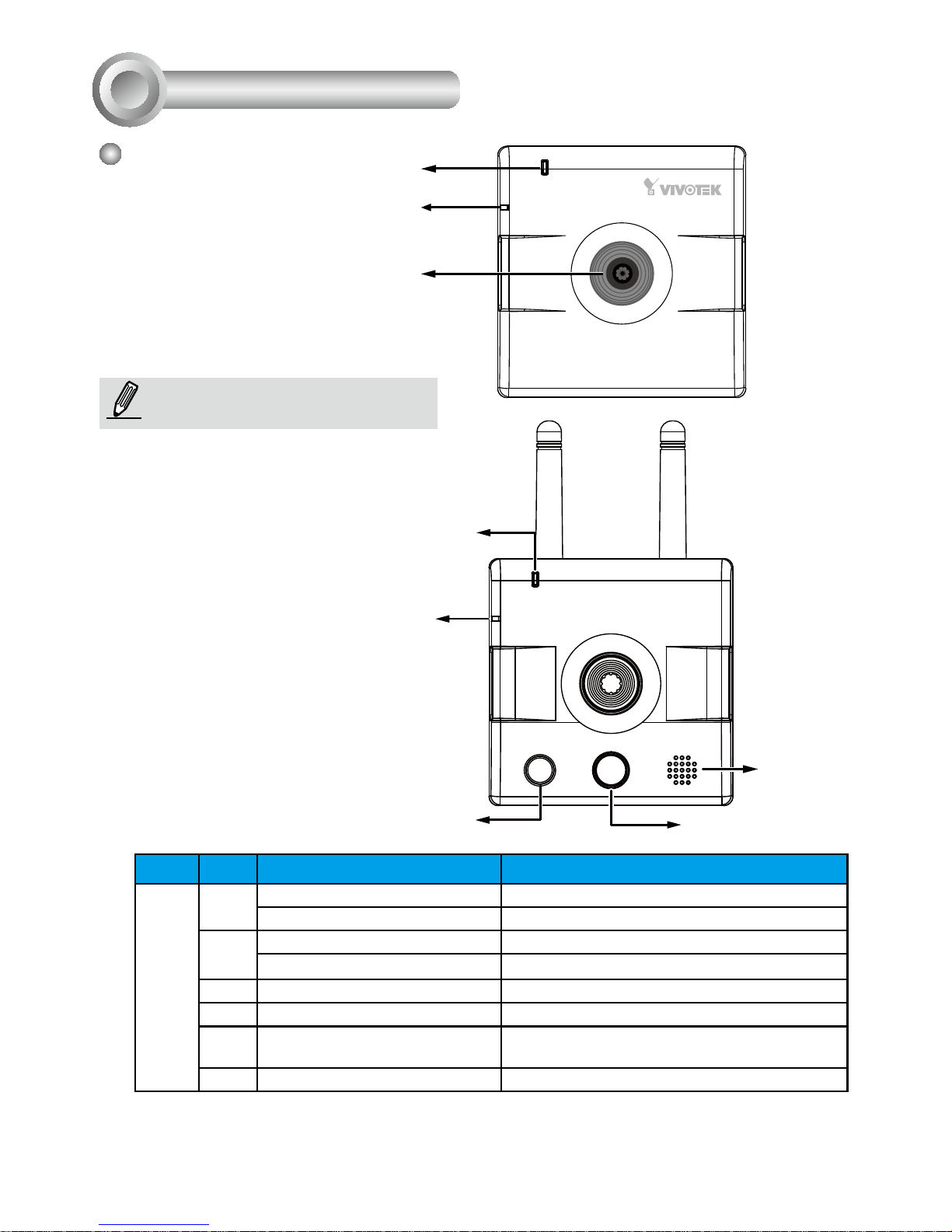
Physical Description
2
Front Panel
Status LED
Lens
Microphone
IP8132
IP8133W
Microphone
White-light LED
Speaker
PIR Sensor
NOTE:
Status LED
Item LED status Description
LED Denitions
1 Steady Red Power on and system boot
Red LED off Power off
2 Blink Green every 1 sec. Network connected
Steady Red Network failed
3 Blink Green every 2 sec. Audio muted
4 Blink Orange every 2 sec. Privacy button pressed
5 Blink Green, RED, and Orange
intermittently
Upgrading rmware
6 Blink Orange every 0.15 sec. Restoring default
The front view of IP8133 is identical to
that of IP8133W except the wireless
antenna.
Page 6
EN - 5
English
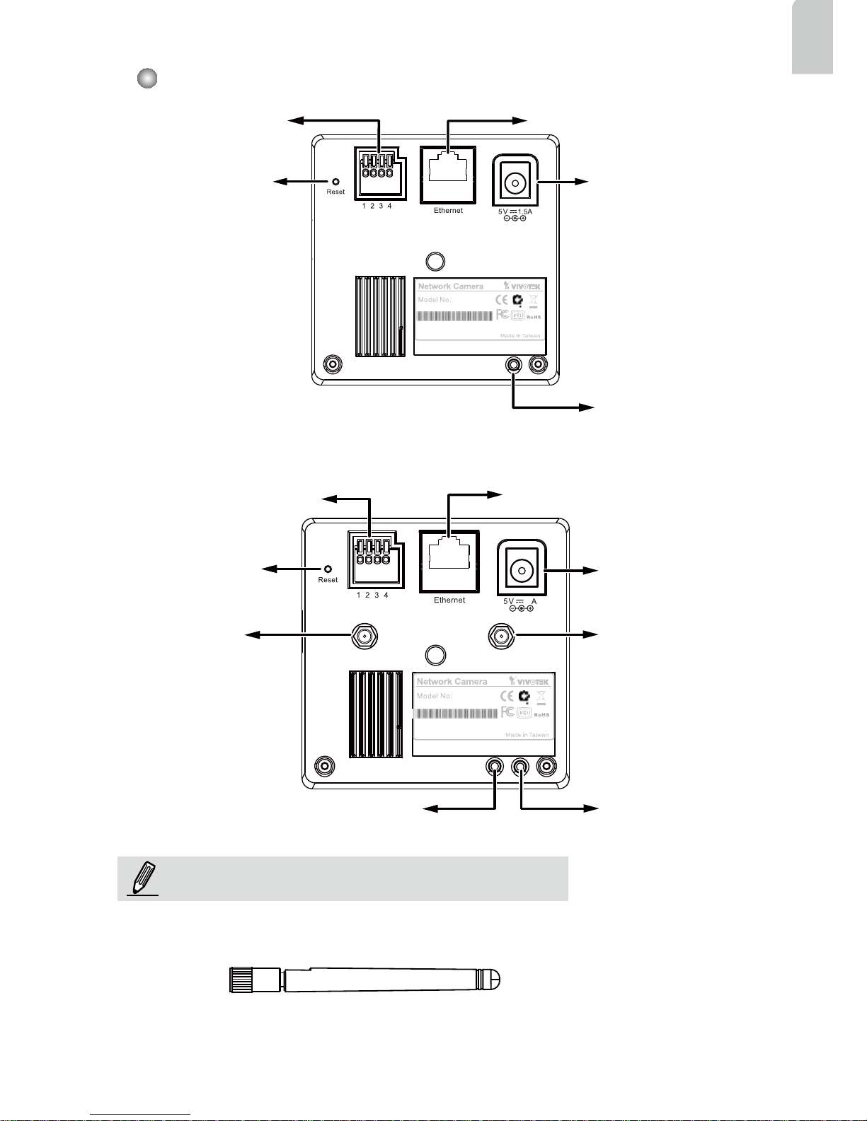
Back Panel
MAC:0002D132C353
IP8132
This device complies with part 15 of the FCC rules. Operation is subject to the following two conditions:
(1)This device may not cause harmful interference, and
(2) this device must accept any interference received, including interference that may cause undesired operation.
Pat. 6,930,709
General I/O Terminal
Block
Recessed Reset Button
Power Cord Socket
Ethernet 10/100 RJ45 Socket
Privacy Button
2
MAC:0002D132C353
IP8133W
This device complies with part 15 of the FCC rules. Operation is subject to the following two conditions:
(1)This device may not cause harmful interference, and
(2) this device must accept any interference received, including interference that may cause undesired operation.
Pat. 6,930,709
IP8133 & 8133W
IP8132
Privacy Button
Antenna
Connector
(IP8133W)
Power Cord
Socket
WPS Button
(IP8133W)
Reset Button
Ethernet 10/100
RJ45 Socket
Antenna
Connector
(IP8133W)
General I/O
Terminal Block
NOTE:
Two antennas come with the IP8133W. They are installed
by users by turning clockwise to attach to connectors.
Page 7
EN - 6
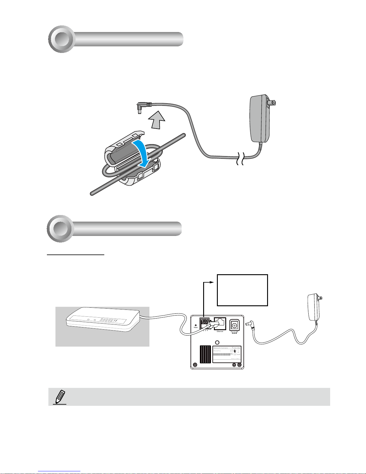
Network Deployment
4
1. If you have external devices such as sensors and alarms, make connections from
general I/O terminal block.
MAC:0002D132C353
IP8132
This device complies with part 15 of the FCC rules. Operation is subject to the following two conditions:
(1)This device may not cause harmful interference, and
(2) this device must accept any interference received, including interference that may cause undesired operation.
Pat. 6,930,709
POWER
COLLISION
LINK
RECEIVE
PARTITION
1
2
3
4
5
3. Connect the supplied
power cable from the
camera to a power
outlet.
2. Connect the camera to a switch
via Ethernet cable.
4: Power
3: Digital output
2: Digital input
1: Ground
LAN Connection
NOTE:
1. Use a Category 5 Cross Cable when
Network Camera is directly connected
to a PC.
2. The IP8133 can acquire power through
a cable connection with a PoE switch.
However, when so connected, the camera
is only to be connected to PoE networks
without routing to outside plants.
Install Ferrite Core
3
1. Unsnap the two halves of the ferrite core.
2. Attach the ferrite core to the power cord as close to the DC connector as possible.
Fold the ferrite core over the power cord, wrap the power cord once, and snap the
small latches together.
Ferrite Core
Page 8
EN - 7
English
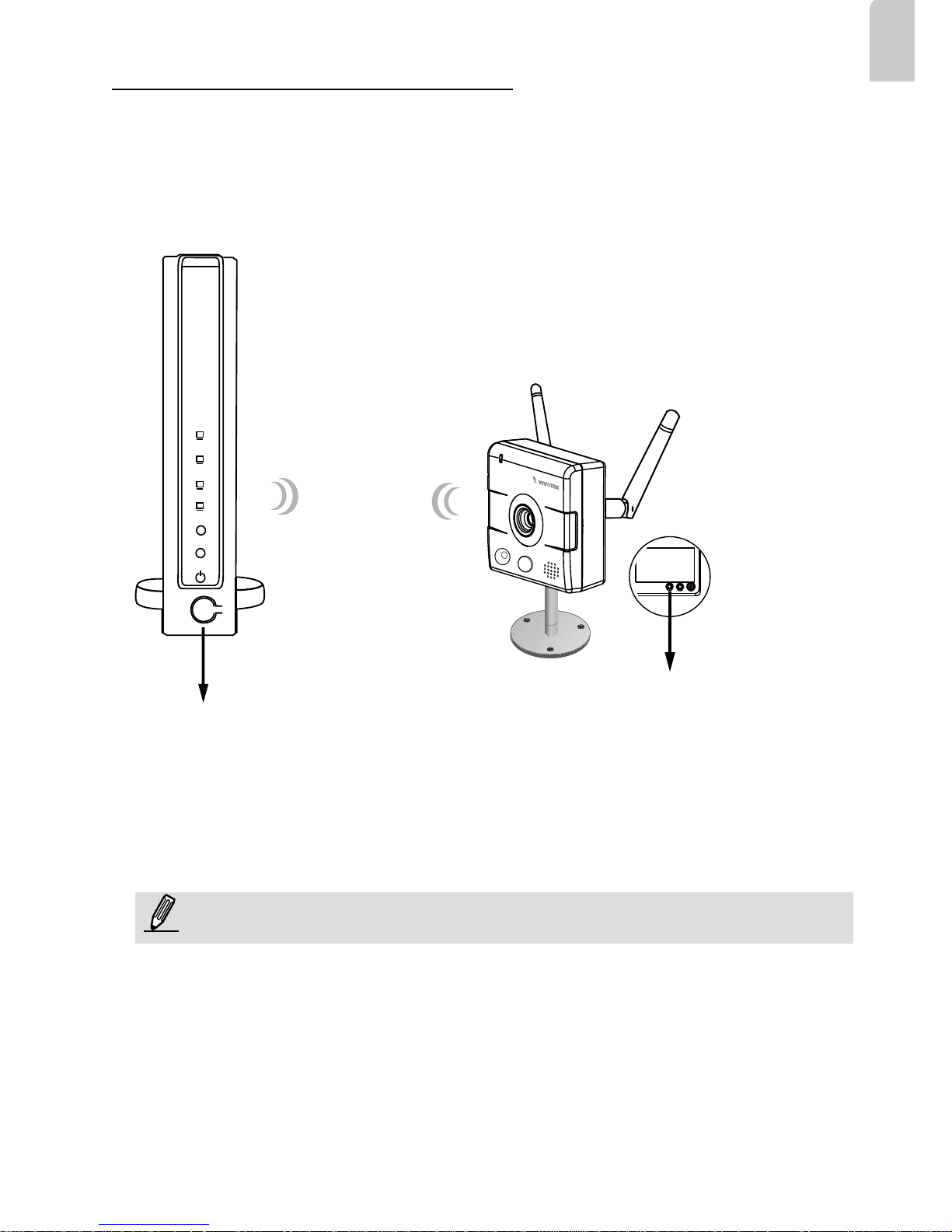
WPS
2
Wireless Connection: Using the WPS Button
1. Make sure your AP (Access Point) and Operating System support WPS (Wi-Fi
Protected Setup) functions. WPS enables easy setup with compatible APs.
2. Disconnect your LAN cable, and wait for the LED to turn red.
3. Press the WPS button for 1 second. You can then hear vocal instructions (in English)
from the camera speaker.
4. Press and hold down the WPS button on your AP
(some router/AP will have a virtual button on their
management software instead). Refer to your AP's
documentation for details using its WPS functions.
When WPS conguration is done, wireless connectivity will be established and the
security encryption, such as WEP or WPA-PSK, will be synchronized with the AP.
Use the IW2 utility to nd the camera. As for IP setting, the camera's use of DHCP
or static IP is determined by your conguration on the network camera via the webbased conguration of rmware. The camera's default is DHCP.
NOTE:
WPS Button
WPS Button
Wireless AP
1. WPS may not work if your AP is congured with a "hidden" SSID.
2. If no WPS-enabled AP is detected, the camera will repeat vocal instructions by
every 20 seconds, and if the camera still can not detect an AP after 2 minutes, the
wireless setup will be cancelled.
3. If a camera is assigned with a xed IP outside the AP's network segment, wireless
setup will fail.
4. A wired connection always has a higher priority, and hence wireless setup will not
take effect when the RJ45 LAN port is connected.
Page 9
EN - 8
MAC:0002D132C353
IP8132
This device complies with part 15 of the FCC rules. Operation is subject to the following two conditions:
(1)This device may not cause harmful interference, and
(2) this device must accept any interference received, including interference that may cause undesired operation.
Pat. 6,930,709
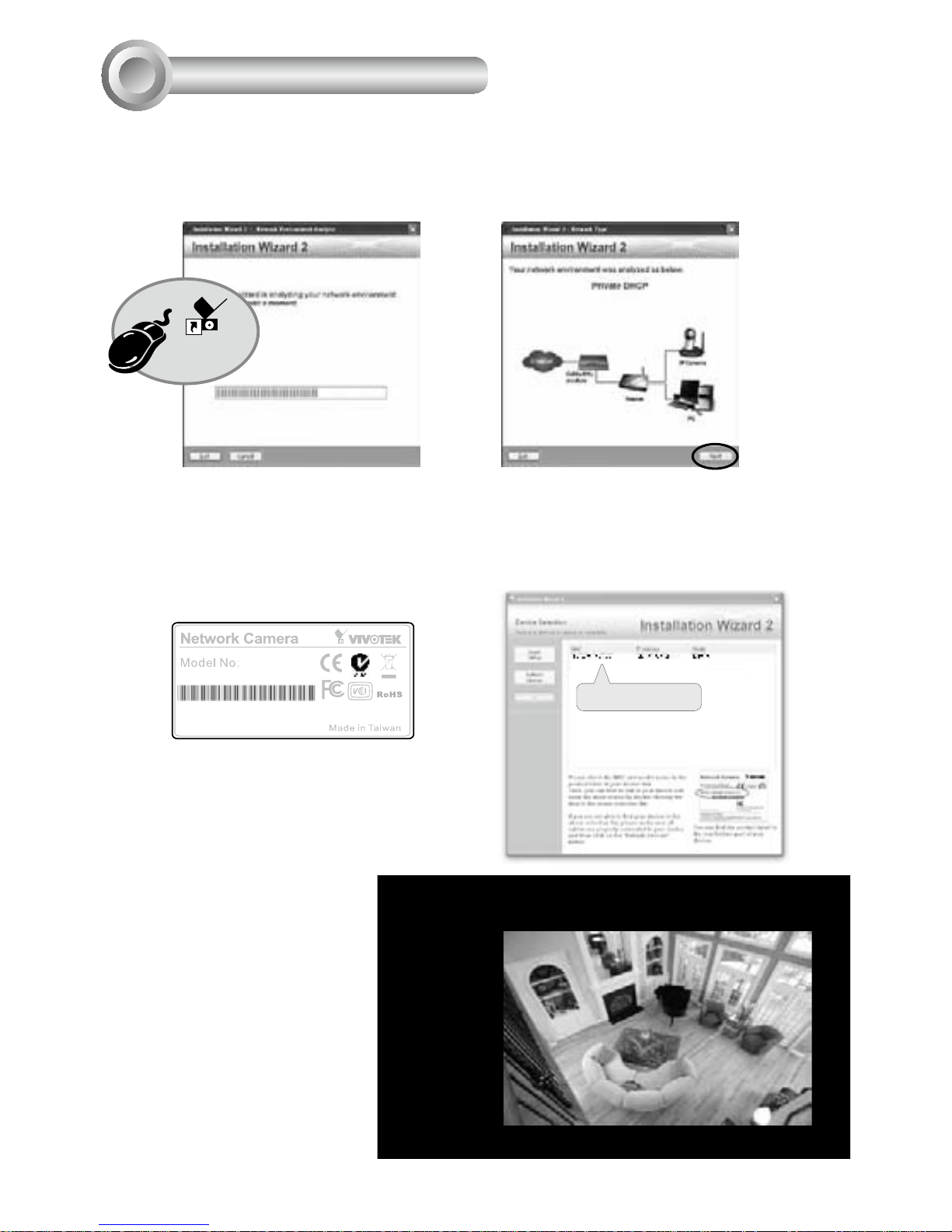
1. Install “Installation Wizard 2” from the Software Utility directory on the software CD.
2. The program will conduct an analysis of your network environment. After your network is
analyzed, please click on the “Next” button to continue the program.
0002D132C353
Installation
Wizard 2
Assigning an IP Address
4
2011/01/05 01:50:28
3. The program will search for VIVOTEK Video Receivers, Video Servers, and Network
Cameras on the same LAN.
4. After a brief search, the main installer window will pop up. Double-click on the MAC
address that matches the one printed on the camera label or the serial number on the
package box label to open a browser management session with the Network Camera.
5. A browser session with the
Network Camera should
prompt as shown below.
6. You should be able to see
live video from your camera.
You may also install the
32-channel recording software from the software CD
in a deployment consisting
of multiple cameras. For its
installation details, please
refer to its related documents.
Page 10

 Loading...