

Page 1
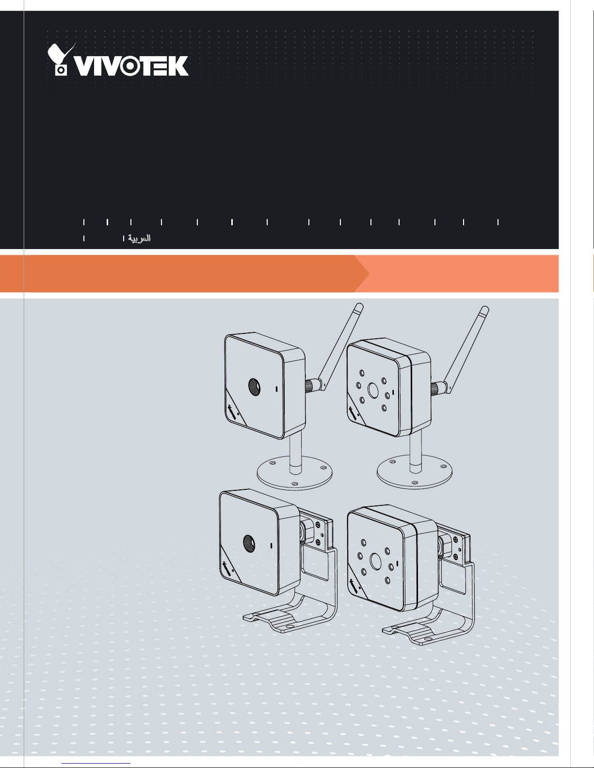
IP8130/8131
Cube
IP8130W/8131W
Network Camera
Quick Installation Guide
繁中 日本語
English
Dansk
IP8130/8131: 1MP • Compact Size
簡中
Indonesia
Français
Español Português
Deutsch
Italiano
Türkçe
Polski
Русский
Česky Svenska
Nederlands
IP8130W/8131W: 1MP •
802.11n WLAN • WPS
Page 2
EN - 1
English
Power off the Network Camera as
soon as smoke or unusual odors are
detected.
Keep the Network Camera away
from water. If the Network Camera
becomes wet, power off immediately.
Do not place the Network Camera
around heat sources, such as a
television or oven.
Refer to your user’s manual for the
operating temperature.
Keep the Network Camera away from
direct sunlight.
Do not place the Network Camera in
high humidity environments.
Warning Before Installation
Do not place the Network Camera on
unsteady surfaces.
Do not touch the Network Camera
during a lightning storm.
Do not disassemble the Network
Camera.
Do not drop the Network Camera.
Do not insert sharp or tiny objects
into the Network Camera.
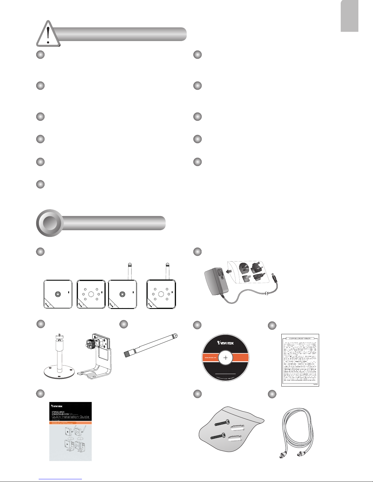
Camera Stand
IP8130W
Warranty Card
Screws
Quick Installation Guide
Power Adaptor (+12V, 1A)
Package Contents
1
Software CD
5
0
0
0
2
4
7
0
1
G
IP8131W
Ethernet Cable
Antenna
IP8130
IP8131
Page 3
EN - 2
Physical Description
2
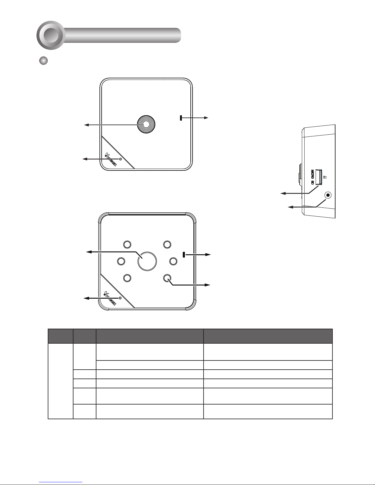
Front Panel
Status LED
Lens
Microphone
IP8130/8130W
IP8131/8131W
Microphone
IR LEDs
Status LED
Item LED status Description
LED Denitions
1 Steady Red Powered on, during system boot, or
indicating no network connection
All LED off Powered off
2 Blinking Blue every 0.15 sec. Searching for WPS
3 Blinking Green every 1 sec. Network connected (wired or wireless)
4 Blinking Green and RED
intermittently
Upgrading rmware
5 Blinking Orange every 0.15 sec. Restoring default
WPS
MicroSD/SDHC/
SDXC Card Slot
Lens
WPS button
Page 4
EN - 3
English
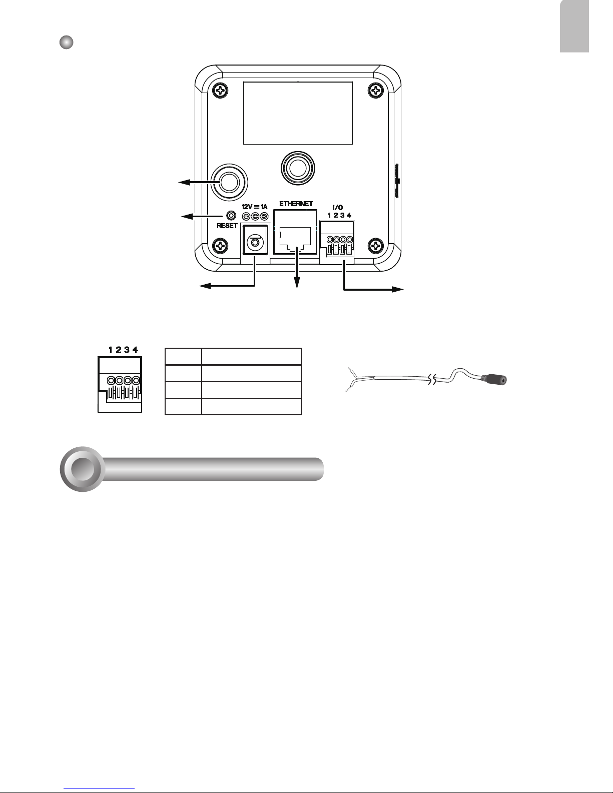
Back Panel
The back panels are identical for all models.
Power Cord
Socket
Reset Button
Ethernet 10/100
RJ45 Socket
General I/O
Terminal Block
1 DI2 DI+
3 Audio GND
4 Audio Out
Audio out cable is user-supplied.
Antenna Connector
(for wireless models)
Install Camera to Stand
3
Attach the camera to stand and orient the shooting angle. If preferred, use the included
screws to secure the the camera stand to a mounting surface.
Page 5
EN - 4
Network Deployment
5
1. If you have external devices such as sensors and alarms, make connections from the
general I/O terminal block.
LAN Connection
POWER
COLLISION
LINK
RECEIVE
PARTITION
1
2
3
4
5
3. Connect the supplied power cable from
the camera to a power outlet.
2. Connect the camera to a switch via Ethernet cable or directly to a computer. Ethernet
must be connected before power on.
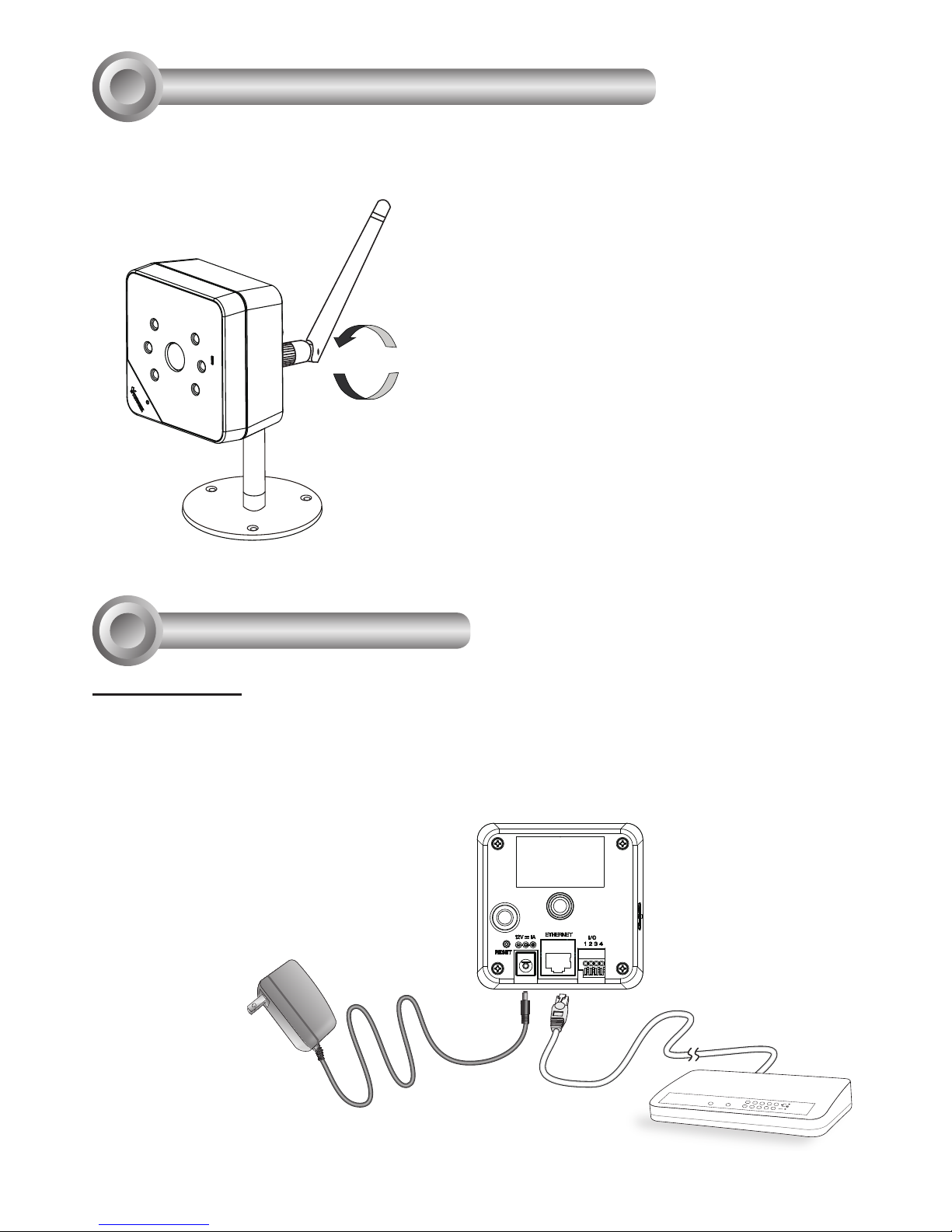
Install the Antenna (wireless models)
4
An antenna comes with the camera. Install it by turning clockwise to attach to the
connector.
Page 6
EN - 5
English
MAC:0002D132C353
IP8130W
This device complies with part 15 of the FCC rules. Operation is subject to the following two conditions:
(1)This device may not cause harmful interference, and
(2) this device must accept any interference received, including interference that may cause undesired operation.
Pat. 6,930,709
The following is performed on a computer connected to the same domain via a wired or
wireless connection.
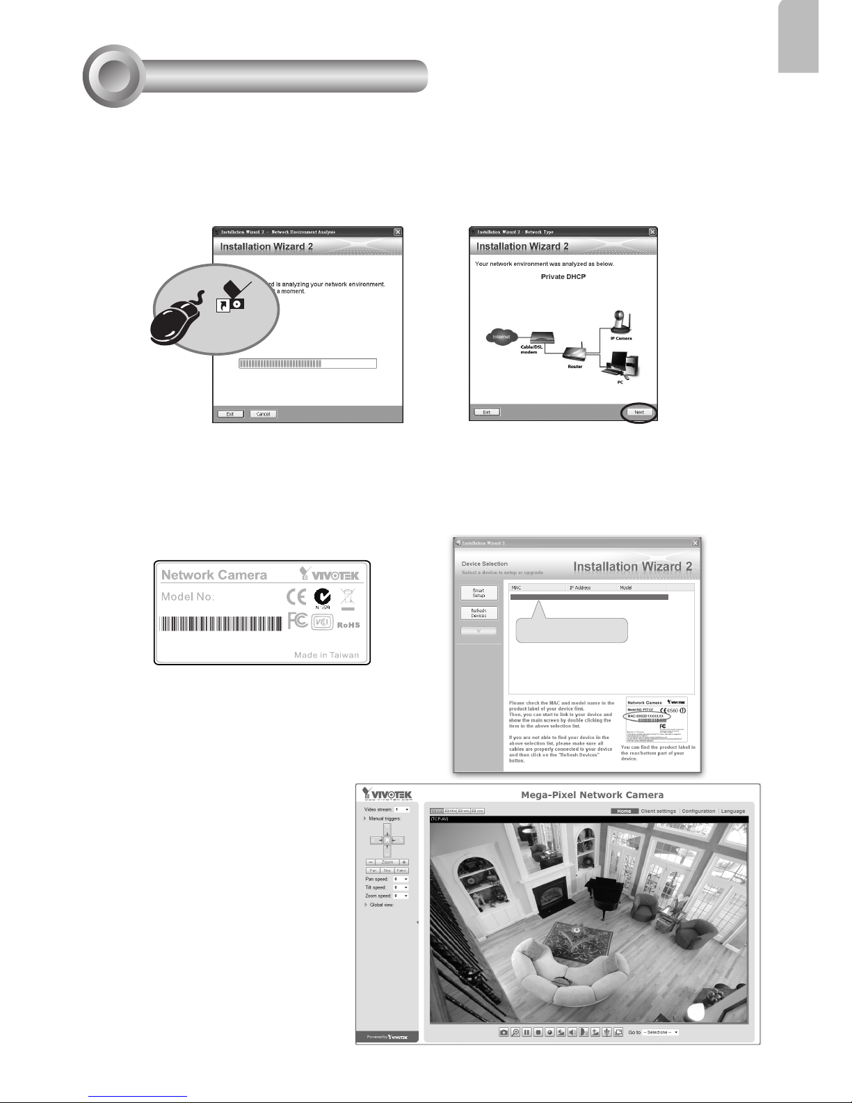
1. Install “Installation Wizard 2” from the Software Utility directory on the software CD.
2. The program will conduct an analysis of your network environment. After your network is
analyzed, please click on the “Next” button to continue the program.
0002D132C353
00-02-D1-32-C3-53 192.168.5.151 IP8130W
Installation
Wizard 2
Assigning an IP Address
6
2012/11/05 01:50:28
3. The program will search for VIVOTEK Video Receivers, Video Servers, and Network
Cameras on the same LAN.
4. After a brief search, the main installer window will pop up. Double-click on the MAC
address that matches the one printed on the camera label or the serial number on the
package box label to open a browser management session with the Network Camera.
5. A browser session with the
Network Camera should prompt
as shown below.
6. You should be able to see live
video from your camera. You
may also install the 32-channel recording software from the
software CD in a deployment
consisting of multiple cameras. For its installation details,
please refer to its related documents.
Page 7
EN - 6
WPS
WPS
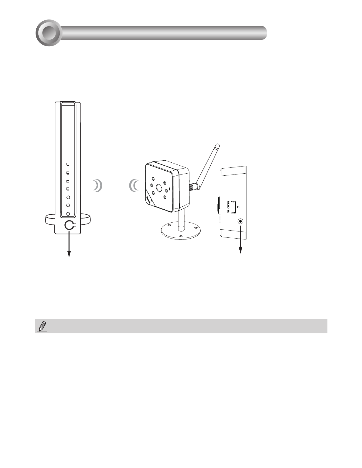
1. Make sure your AP (Access Point) and Operating System support WPS (Wi-Fi Protected
Setup) functions. WPS enables easy setup with compatible APs.
2. Disconnect your LAN cable, and connect the power cord.
3. Wait for 1 minute for the camera to boot up. Press the WPS button for 1 second. The
front panel LED should blink blue.
4. Press and hold down the WPS button on your AP (some router/AP
will have a virtual button on their management software instead).
Refer to your AP's documentation for details using its WPS
functions.
When WPS conguration is done, wireless connectivity will be established and the
security encryption, such as WEP or WPA-PSK, will be synchronized with the AP.
Use the IW2 utility to nd the camera. As for IP setting, the camera's use of DHCP or
static IP is determined by your conguration on the network camera via the web-based
conguration of rmware. The camera's default is DHCP.
NOTE:
WPS Button
WPS Button
Wireless AP
1. It is strongly recommended to apply WPA2/AES encryption for access security.
2. WPS may not work if your AP is congured with a "hidden" SSID.
3. If no WPS-enabled AP is detected, and if the camera still can not detect an AP after 2
minutes, the wireless setup will be cancelled. If WPS conguration should fail, wireless
conguration will be cleared. You can then re-try the process above or use a wired
connection to establish a web console and manually congure the wireless settings.
4. If a camera is assigned with a xed IP outside the AP's network segment, wireless setup
will fail.
5. A wired connection always has a higher priority, and hence wireless setup will not take
effect when the RJ45 LAN port is connected.
Wireless Connection: Using the WPS Button
7
Page 8
EN - 7
English
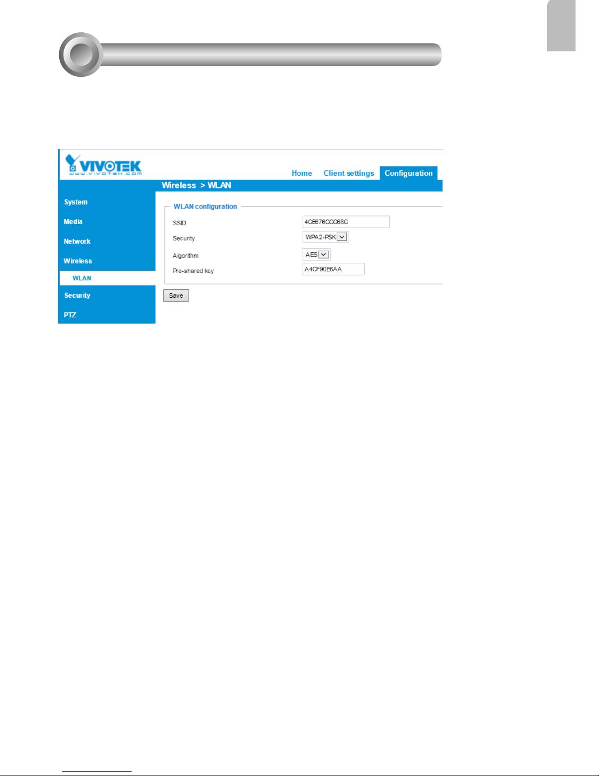
1. In addition to the use of WPS function, you can also use a wired connection to manually
set up your wireless conguration.
2. Enter the Conguration > Wireless > WLAN page. Key in the same wireless settings
as those on your router/AP (SSID, Encryption type, and Pre-shared key).
Wireless Connection: Manual Conguration
8
3. When done, click the Save button, disconnect the Ethernet cable and then reboot the
camera (by disconnect and then connect the power cord). The camera should then be
connected over the wireless network. If successfully congured, the camera LED should
turn Green after 1 minute. If the camera LED does not turn Green within 2 minutes,
check your wireless conguration for errors.
Page 9
P/N:625021700G Rev. 1.0
All specications are subject to change without notice.
Copyright 2013 VIVOTEK INC. All rights reserved.
c
VIVOTEK INC.
6F, No.192, Lien-Cheng Rd., Chung-Ho, New Taipei City, 235, Taiwan, R.O.C.
VIVOTEK USA, INC.
2050 Ringwood Avenue, San Jose, CA 95131
 Loading...