

Page 1
Page 2
EN - 1
English
Contact your distributor in the event of
occurrence.
Keep the Network Camera
away from water. If the Network
Camera becomes wet, power off
immediately.
Refer to your user’s manual for the
operating temperature.
Power off the Network Camera as
soon as smoke or unusual odors
are detected.
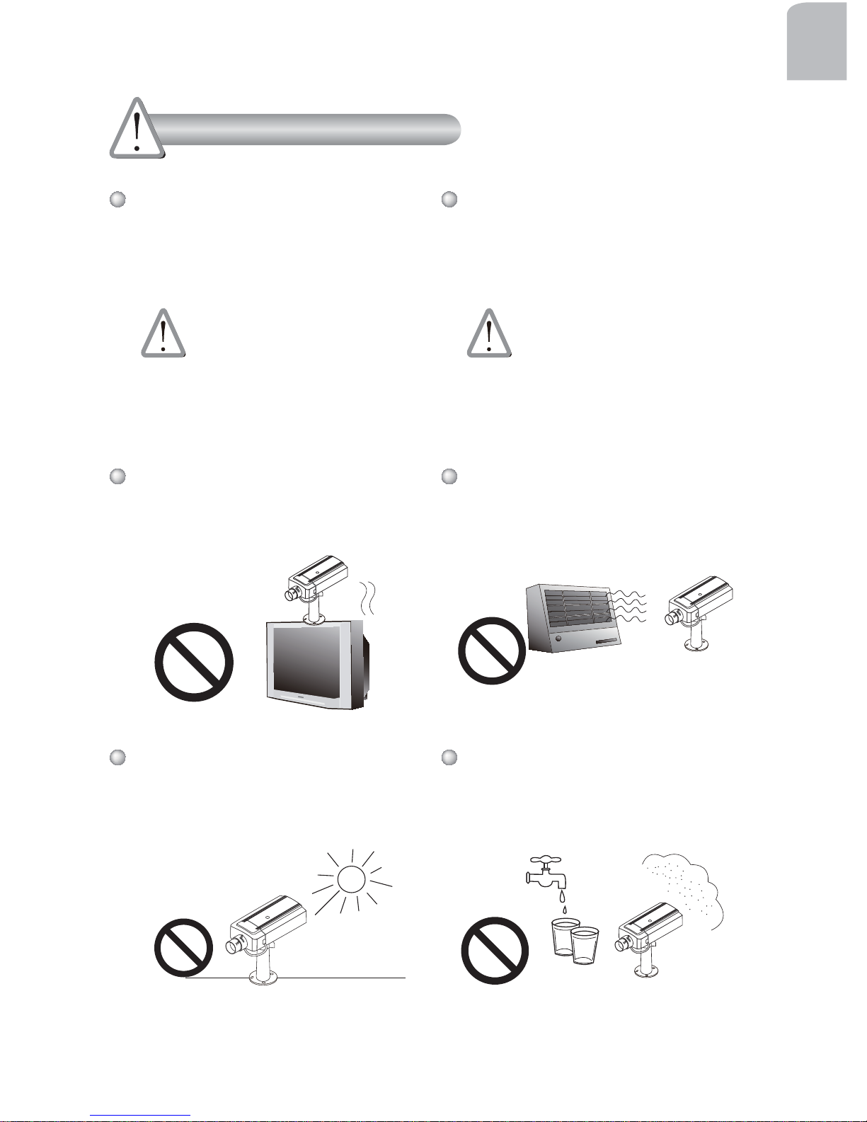
Do not place the Network Camera
around heat sources, such as a
television or oven.
Keep the Network Camera away
from direct sunlight.
Do not place the Network Camera
in high humidity environments.
Contact your distributor in the event of
occurrence.
Warning Before Installation
Page 3
EN - 2
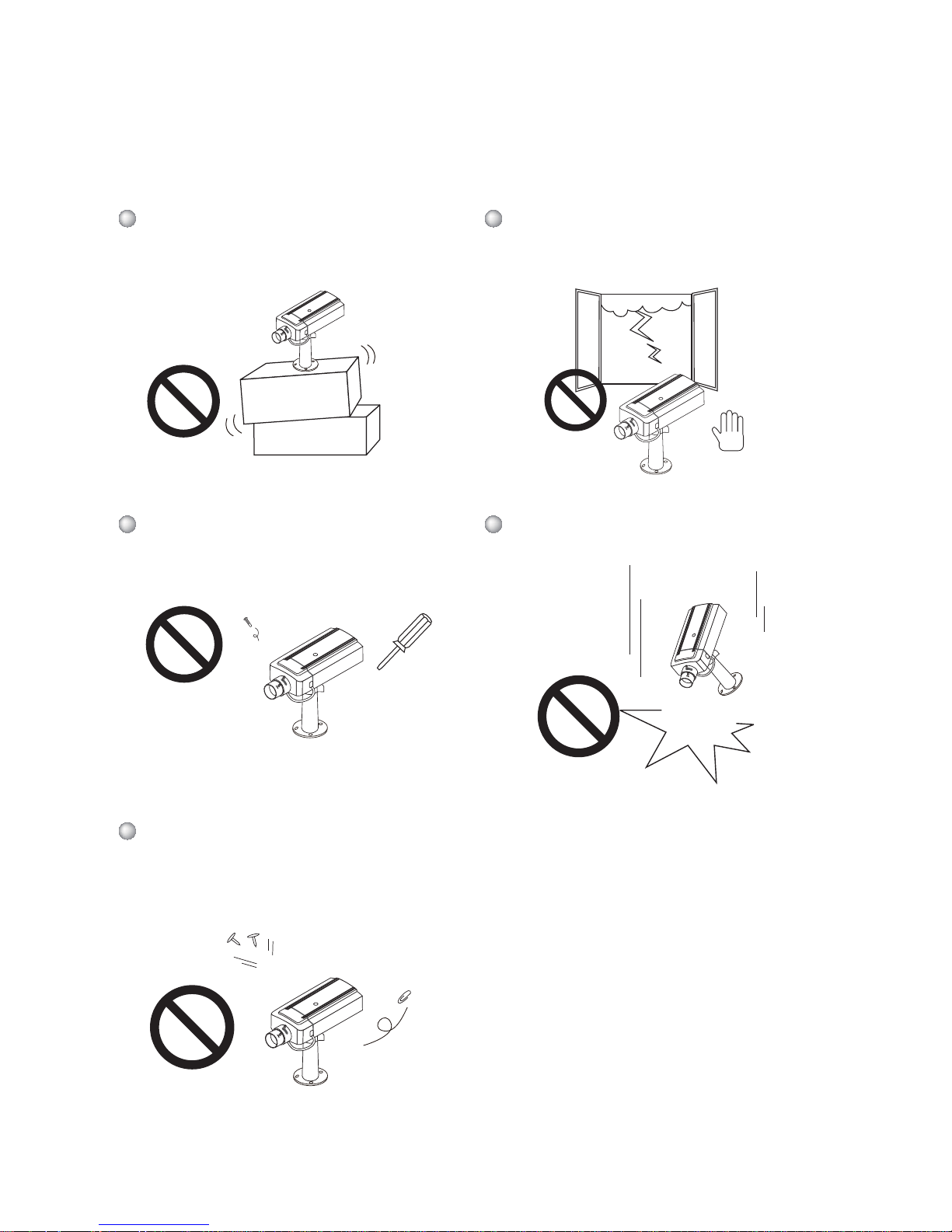
Do not place the Network Camera
on unsteady surfaces.
Do not touch the Network Camera
during a lightning storm.
Do not disassemble the Network
Camera.
Do not drop the Network Camera.
Do not insert sharp or tiny objects
into the Network Camera.
Page 4
EN - 3
English
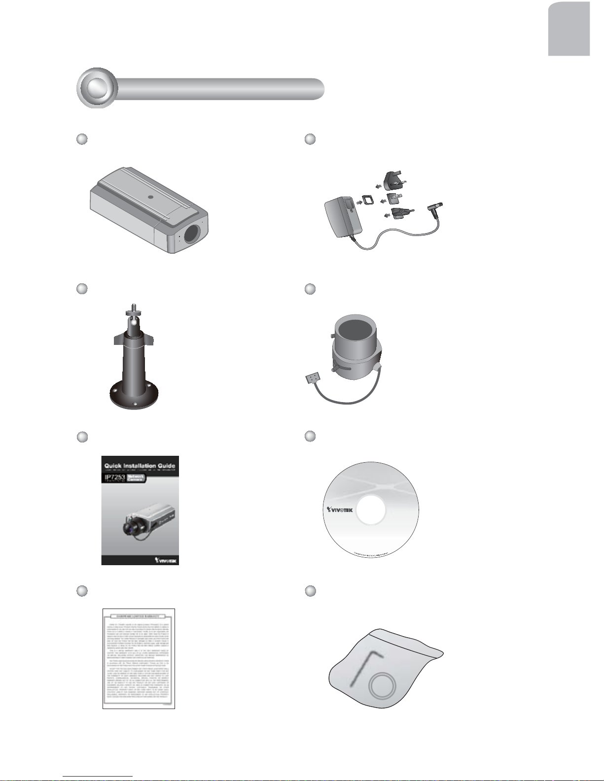
Camera Stand
CS-mount Lens
IP7253
Warranty Card
Power Adapter
Quick Installation Guide
Software CD
1
Package Contents
L-type Hex Key Wrench / C-mount
Ring (for C-mount Lens)
Page 5
EN - 4
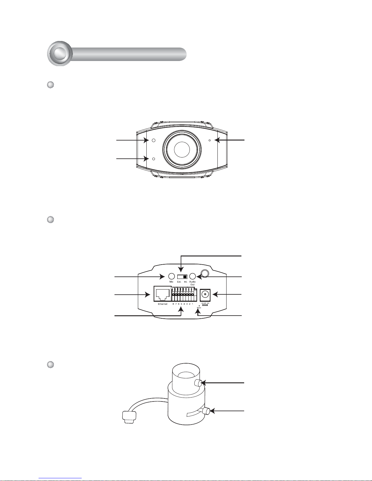
Power Cord Socket
Ethernet 10/100
RJ45 Socket
Recessed Reset Button
General I/O
Terminal Block
Audio Out
Microphone In
External/Internal
MIC Switch
Front Panel
Back Panel
Lens
Focus Controller
Zoom Controller
2
Physical Description
Built-in Microphone
Light Sensor
Status LED
Page 6
EN - 5
English
2
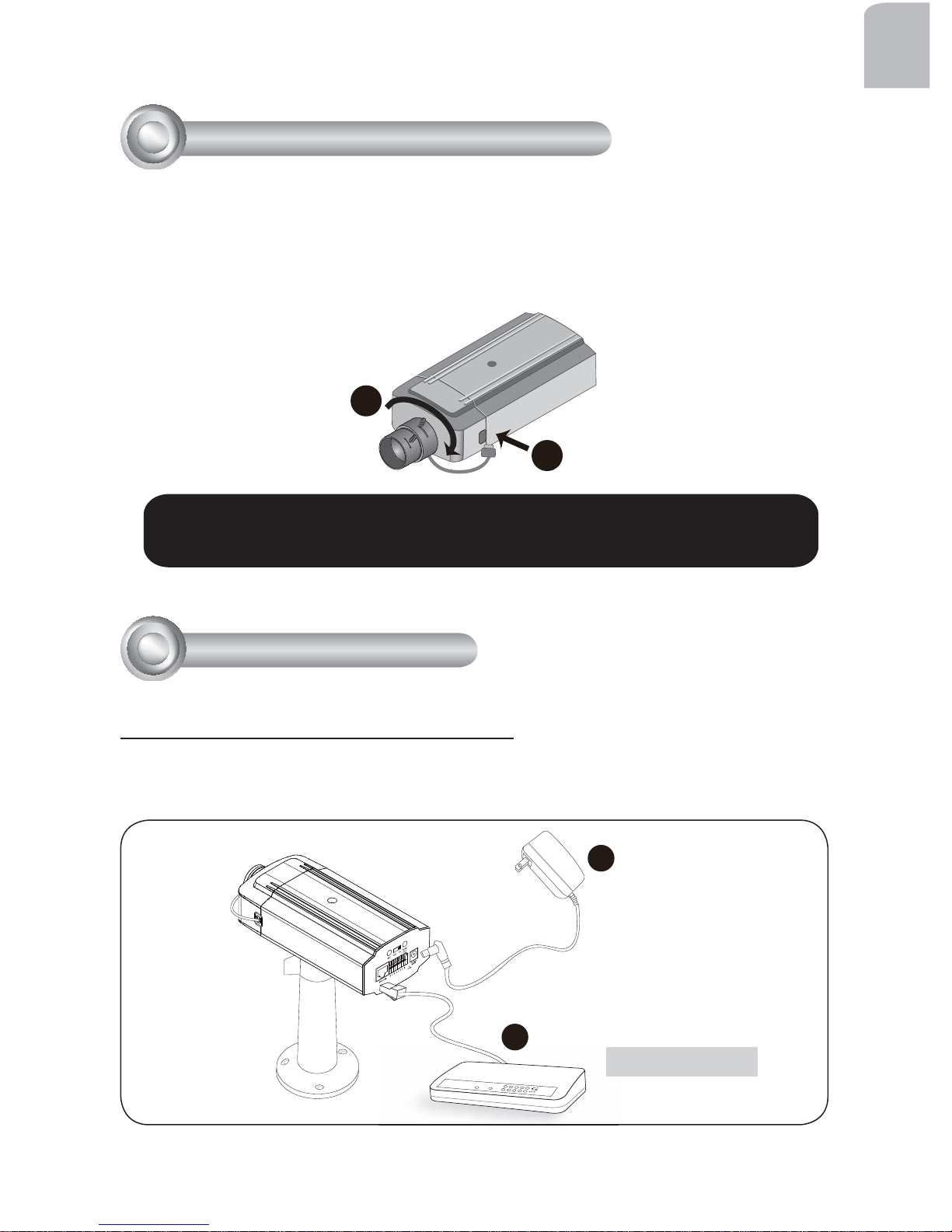
For further setup, please refer to the lens' instruction manual inside the
lens package.
1. Mount the lens by turning it clockwise onto the camera mount until it stops. If
necessary, turn the lens counterclockwise slowly to achieve the best optimum
spacing.
2. Connect the lens cable plug to the camera connector.
3
Mounting the Lens to the Camera
1
2
General Connection (without PoE)
1. Connect the camera to a switch via Ethernet cable.
2. Connect the supplied power cable from the camera to a power outlet.
POWER
COLLISION
LINK
RECEIVE
PARTITION
1
2
3
4
5
1
2
4
Network Deployment
Ethernet Switch
Page 7
EN - 6
POWER
COLLISION
LINK
RECEIVE
PARTITION
1
2
3
4
5
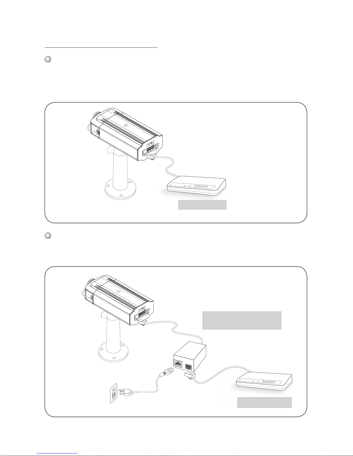
Power over Ethernet (PoE)
When using a non-PoE switch
Use a PoE power injector (optional) to connect between the Network Camera and
a non-PoE switch.
POWER
COLLISION
LINK
RECEIVE
PARTITION
1
2
3
4
5
Non-PoE Switch
PoE Power Injector
(optional)
When using a PoE-enabled switch
This Network Camera is PoE-compliant, allowing transmission of power and data
via a single Ethernet cable. Follow the below illustration to connect the Network
Camera to a PoE-enabled switch via Ethernet cable.
PoE Switch
Page 8
EN - 7
English
This device complies with part 15 of the FCC rules. Operation is subject to
the following two conditions:
(1)This device may not cause harmful interference, and
(2) this device must accept any interference received, including interference
that may cause undesired operation.
RoHS
Network Camera
Model No: IP7253
Pat. 6,930,709 Made in Taiwan
Mac: 0002D106DB41
00-02-D1-06-DB-41 192.168.5.151 IP7253
0002D106DB41
Installation
Wizard 2
IW
2
5
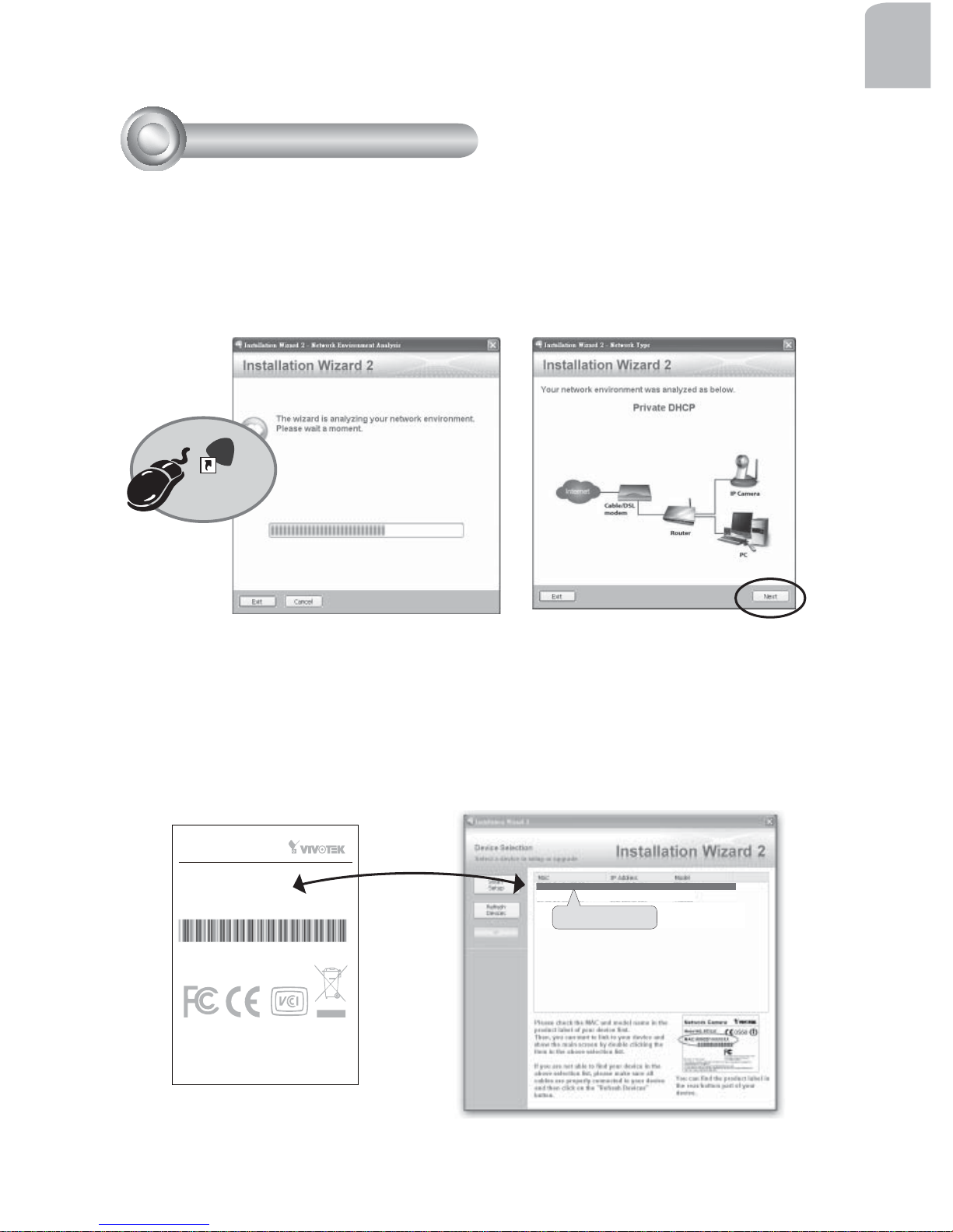
Assigning an IP Address
1. Install "Installation Wizard 2" from the Software Utility directory on the software
CD.
2. The program will conduct an analysis of your network environment. After your
network is analyzed, please click on the "Next" button to continue the program.
3. The program will search for VIVOTEK Video Receivers, Video Servers, and
Network Cameras on the same LAN.
4. After searching, the main installer window will pop up. Click on the MAC that
matches the one labeled on the bottom of your device to connect to the Network
Camera via Internet Explorer.
Page 9
EN - 8
For further setup, please refer to the user's manual on the software CD.
Ready to Use
6
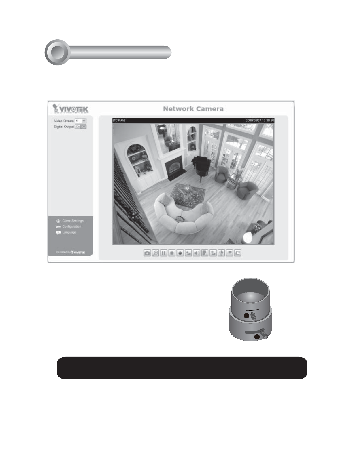
1. Access the Network Camera on the LAN.
2. Retrieve live video through the web browser or recording software.
3. Unscrew the zoom controller to adjust the
zoom factor. Upon completion, tighten the
zoom controller.
4. Unscrew the focus controller to adjust the
focus range. Upon completion, tighten the
focus controller.
W
∞
N
T
3
4
Page 10
EN - 9
English
Fine-tune the Camera Focus
7
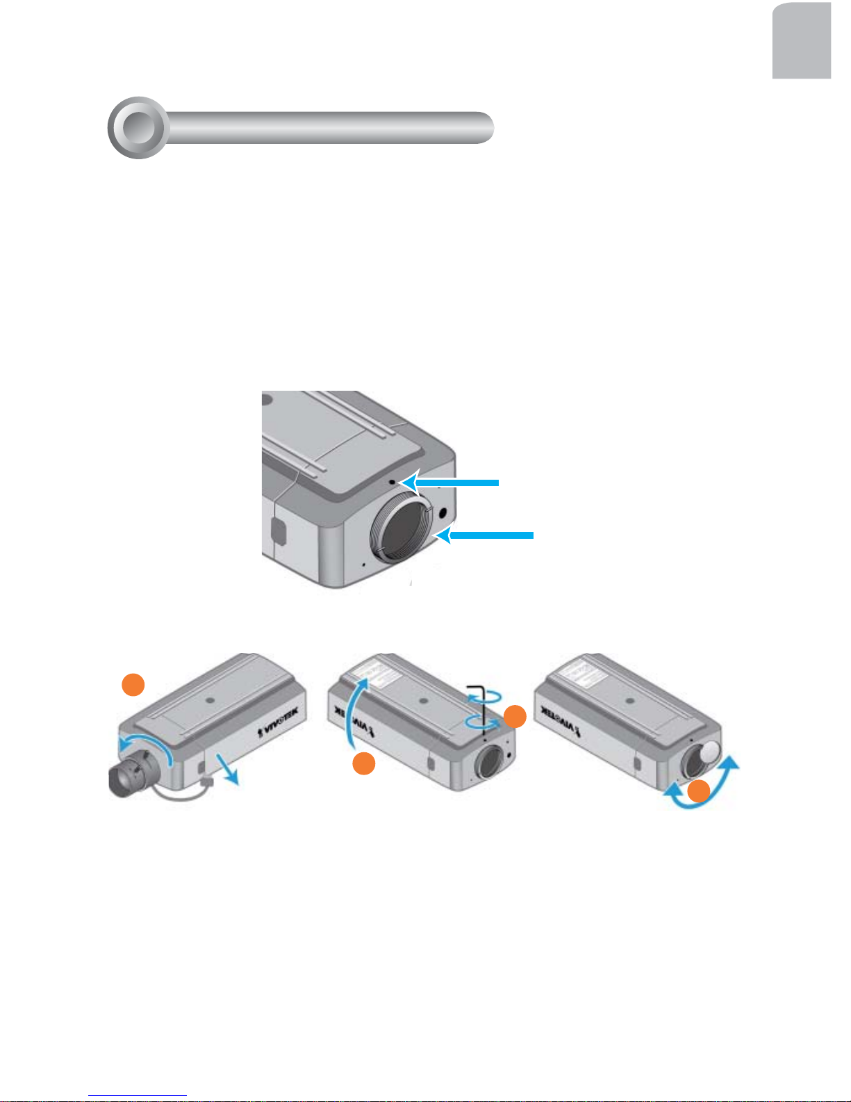
1. Detach the CS-mount lens from the camera body.
2. Turn the camera body bottom up.
3. Use the supplied L-type hex key wrench to loosen the lens mounting screw; the
CS-mount ring becomes rotatable.
4. Use a coin to turn the CS-mount ring; fi ne-tune the distance between the sensor
and the lens.
5. When fi nished, tighten the lens mounting screw to fi x the CS-mount ring.
6. Attach the CS-mount lens back to the camera body.
Lens Mounting Screw
CS-mount Ring
1
2
3
4
Page 11

 Loading...