

Page 1
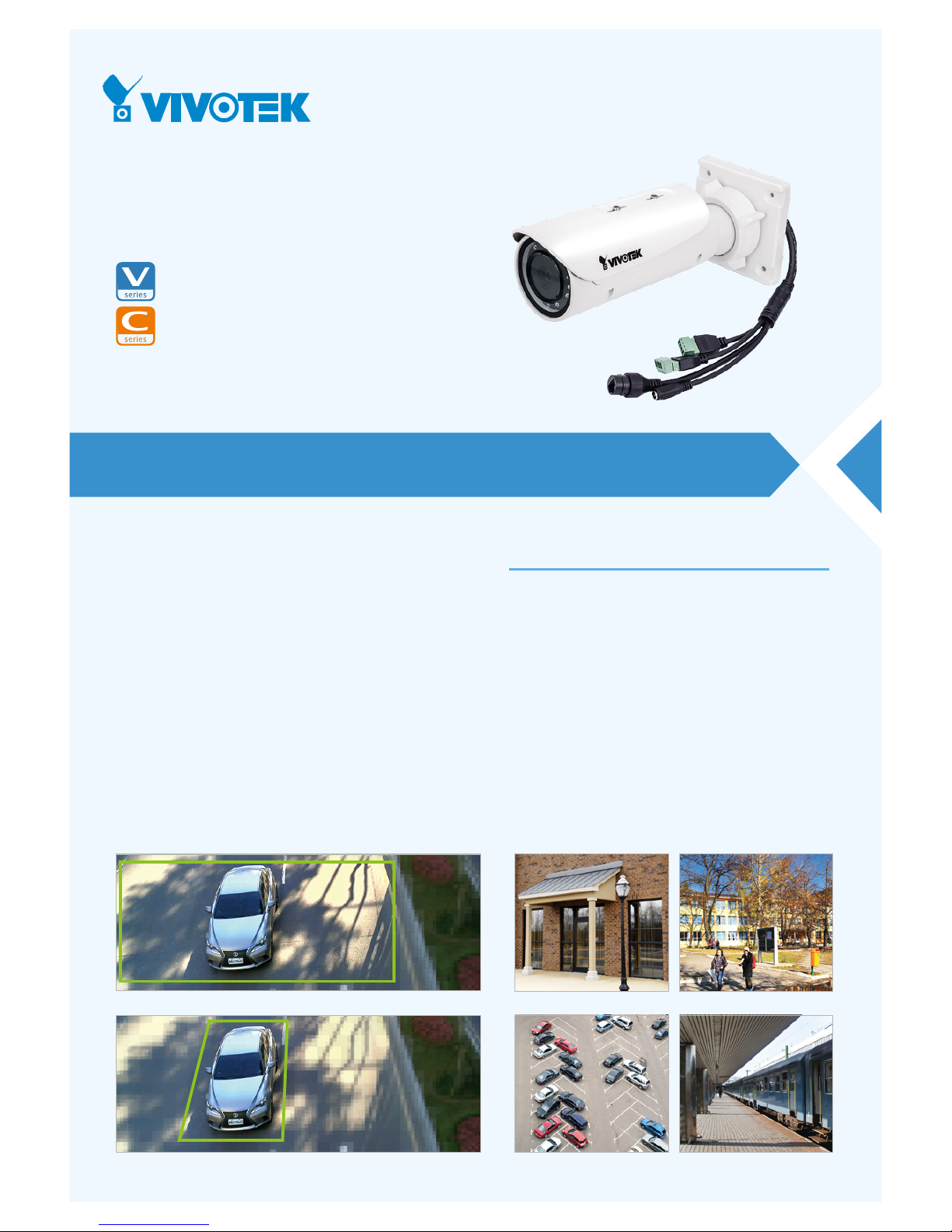
IB8382-T/-E T
IB8382-F3/-EF3
Bullet Network Camera
5MP • 30M IR • WDR Enhanced • 3DNR • P-iris • Remote Focus • Smart Stream • Smart IR •
Video Rotation • IP66 • IK10 • Cable Management • Extreme Weather • Defog
VIVOTEK’s IB8382 is a seri es of economic professional outdoor bullet network came ras
in VIVTOTEK’s 5MP Lite series which of fer up to 15 fps at 5-Me gapixel or 30 fps at
1080p resolution at a competitive pr ice. Equipp ed with a new high resol ution image
sensor, different from other 5MP cameras , the IB8382 series provi des sharper image
qualit y and finer det ail at a cost-eff ective price. And wit h powerful 3D Noise Reduct ion
technol ogy and Smar t Stream technology the IB8382 series can als o optimize resolution
for a desired objec t or area to maximize effici ency of bandwidt h usage.
To create the perfec t focus requi red to reap the bene fits of higher resoluti ons,
VIVOTEK’s IB8382 series provide s the options of both fi xed focus, used for simpl e
operat ion witho ut electr ical power, and remote focus with built-in stepp ing motor s and
P-iris for pre cise adjustm ent remote ly.
To provide higher res olution in outdoor and har sh environm ents, VIVOTEK’s IB8382
series is also arm ed with IP66-rated housing to help the camer a body withstand rai n,
dust and high pressur e water jets fro m any directi on, while its IK10-rated housing
provides protec tion agai nst acts of vandalism or other impacts. Addit ionall y, a wide
operat ing temper ature range further improves the IB8382-EF3 and IB8382-ET’s
performance and reliabil ity in extr emely col d or warm weathe r, even when using PoE.
With the highl y flexib le VADP (VIVOT EK Applic ation Dev elopme nt Platform), users can
extend the features of this seri es by adding third -par ty appl ications for the IB8382-F3,
IB8382-EF3, IB8382-T, and IB8382-E T. Thus the IB8382 series is not only equipp ed with
multiple focusing meth ods and wide temp erature range opti ons, is but ideal for a wide
variety of applic ations.
• 5-Megapixel CMOS Se nsor
• 15 fps @ 2560x1920, 30 fps @ 1920x1080
• 3 ~ 9 mm, Vari-focal , Remote Focus, P-ir is Lens (IB8382-T/-E T)
• Remov able IR-cu t Filter for Day & Night Function
• Built-i n IR Illuminator s, Effec tive up to 30 Meters
• Smar t IR Technology to Avoid Ov erexp osure
• Smar t Stream to Optim ize Bandw idth Eff iciency
• WDR Enha ncement for Unparalleled Visib ility in Ex tremely Bright and Dark
Environments
• 3D Noise Reduc tion for Low -light Con ditions
• Two-wa y Audio
• Vide o Rotation for Corridor Vi ew
• Weather-proof IP66-ra ted and Vandal -proof IK10-rated Housin g
• Ext reme Weath er Suppor t with PoE (IB8382-EF3/-E T)
• VIVOT EK VCA (Vid eo Content An alysis) Supp ort
Key Features
Entrance
Parking Lot
Campus
Train Station
Smart Stream - Manual Mode
Smart Stream - Auto Mode
Page 2
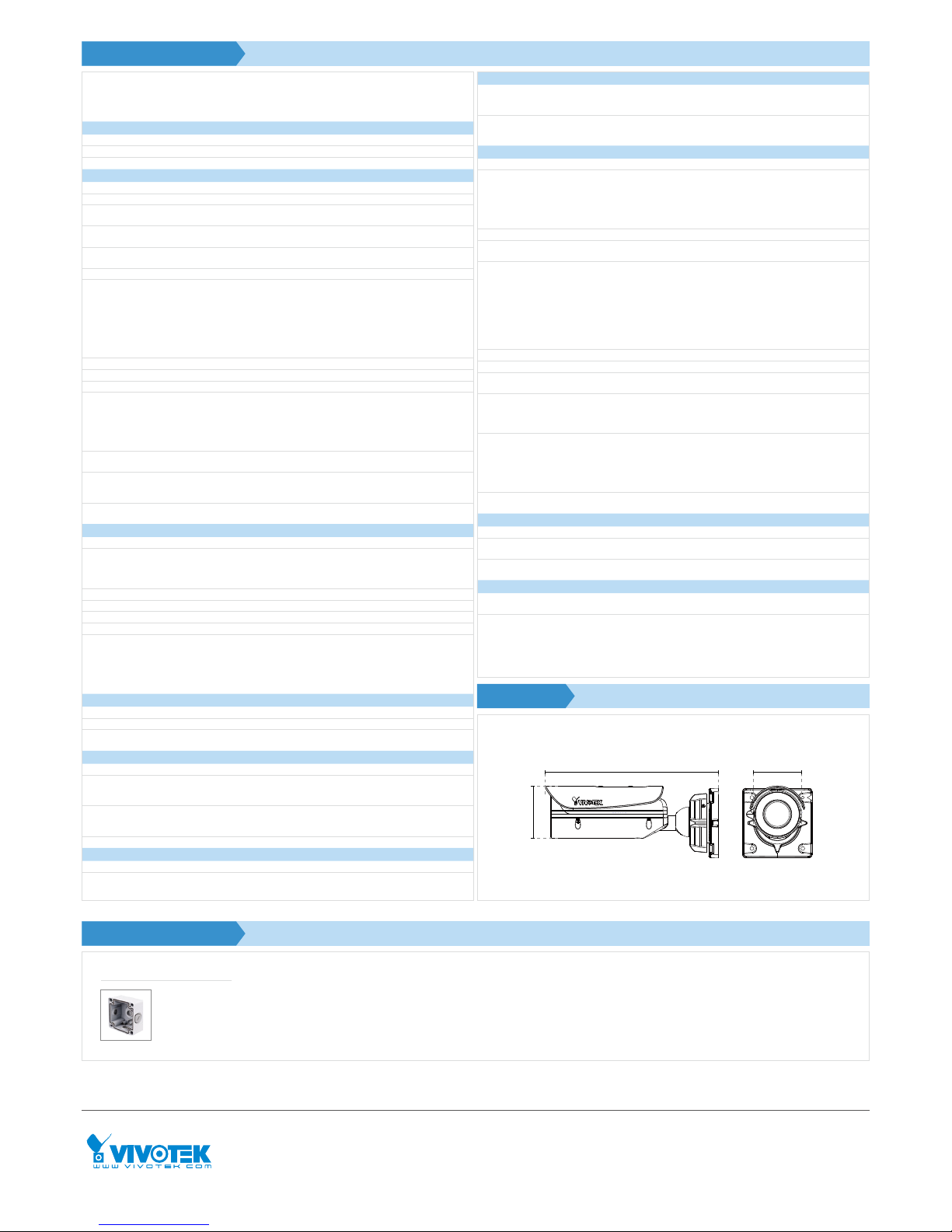
Model
IB8382-T: Vari-f ocal, P- iris, Remote Foc us
IB8382-ET: Vari-foca l, P-iris, Rem ote Focus, Ex treme
Weather
IB8382-F3: Fixed-foc al
IB8382-EF3: Fixed-fo cal, Ext reme Weathe r
System Information
CPU Multimed ia SoC (System -on- Chip)
Flash 1Gb
RAM 4Gb
Camera Features
Image Senso r 1/3.2" Progressive CM OS
Maximum Resolution 2560x1920 (5MP)
Lens Type
Vari-fo cal, Remote Fo cus (IB8382-T/-E T)
Fixed-fo cal (IB8382-F3/-EF3)
Focal Len gth
IB8382-T/IB8382-ET: f = 3 ~ 9 mm
IB8382-F3/IB8382-EF3: f = 3.6 mm
Aperture
IB8382-T/IB8382-ET: F1.2 ~ F2.3
IB8382-F3/IB8382-EF3: F2.1
Auto-iris P-iris (IB8382-T/IB8382-ET)
Field of View
IB8382-T/IB 8382-E T:
35° ~ 78° (Horizontal)
27° ~ 54° (Vertical )
44° ~ 100° (Diagonal)
IB8382-F3/IB8382-EF3:
92° (Horizont al)
76° (Vertic al)
105° (Diagonal)
Shutte r Time 1/5 sec. to 1/32,000 sec.
WDR Technolog y WDR Enhanc ed
Day/Night Removab le IR-cut fil ter for day & night func tion
Minimum Illumination
IB8382-T/IB 8382-E T:
0.04 Lux @ F1.2 (Color)
0.001 Lux @ F1.2 (B/ W)
IB8382-F3/IB8382-EF3:
0.089 Lux @ F2.1 (Col or)
0.001 Lux @ F2.1 (B/ W)
Pan/tilt/zoom Functionalities
ePTZ:
48x digital zoo m (4x on IE plug-in, 12x built in)
IR Illuminators
Built-in IR illumi nators, ef fecti ve up to 30 meters
with Smar t IR
IR LED*8
On-board Storage
Slot typ e: SD/SDHC/SDXC car d slot
Seamle ss Recording
Video
Compression H.264 & MJPEG
Maximum Fra me Rate
15 fps @ 2560x1920
15 fps @ 2408x1536
30 fps @ 1920x1080
In both compre ssion modes
Maximum Streams 4 simultane ous streams
S/N Ratio Above 65 dB
Dynam ic Range 70 dB
Video Stre aming Adjustab le resolut ion, qualit y and bitra te; Smart Stre am
Image Set tings
Adjustab le image size, quali ty and bit rate , time stamp,
text over lay, flip & mirror, confi gurable br ightnes s,
contra st, saturat ion, sharpn ess, white bal ance, expos ure
control, ga in, backlig ht compens ation, pri vacy ma sks,
schedule d profile se ttings, 3D nois e reducti on, video
rotation, defog
Audio
Audio Capability Two-way Audio (full dup lex)
Compression G.711, G.726
Interface
External microphone input
Audio output
Network
Users Live view ing for up to 10 clients
Protocols
IPv4, IP v6, TCP/IP, HTTP, HTTPS, UPnP, RTSP/RTP/RTCP,
IGMP, SMTP, FTP, DHCP, NTP, DNS, DDNS, PPP oE, CoS,
QoS, SNMP, 802.1X, UDP, ICMP, ARP, SSL, TLS
Interface
10Base-T/100 BaseTX Ethernet (RJ -45)
*It is highly reco mmende d to use standard Ca t. 5e & Cat.
6 cables whic h are complian t with the 3P/ETL stan dard.
ONVIF Suppor ted, speci ficat ion availa ble at ww w.onvif.or g
Intelligent Video
Video Motion Detection Five- window vi deo motio n detectio n
VC A*
Line crossing de tectio n, field det ection , loiterin g
detection
Technical Specifications
Compatible Accessories
Alarm and Event
Alarm Triggers
Video moti on detect ion, manua l trigger, digit al input,
period ical trig ger, system boot , recordin g notific ation,
camera tampering detection, audio detection
Alarm Events
Event notif icati on using digita l output, HT TP, SMTP, FTP
and NAS ser ver, SD Card
File upload vi a HTTP, SMTP, FTP, NAS server and SD ca rd
General
Smart Foc us System IB8382-T/IB8382-ET: Remo te Focus
Connectors
RJ-45 cable co nnecto r for Netwo rk/Po E connecti on
Audio input
Audio output
DC 12V power input
Digita l input*1
Digita l output*1
LED Indica tor Sy stem powe r and status indic ator
Power Inpu t
DC 12V
IEEE 802.3at PoE
Power Consumption
IB 838 2- T:
Max. 8 W (DC12V)
Max. 9.5 W (PoE)
IB8382-ET/-EF3:
Max. 21/8 W (DC12V-Heater on/of f)
Max. 25/9.5 W (PoE-Heater on/off )
IB8 382- F3:
Max. 7.5 W (DC12V)
Max. 9 W (PoE)
Dimensions Ø 88 x 293 mm
Weight Net: 1264 g
Casing
Weather-p roof IP66 -rated ho using
Vandal- proof IK10-rat ed metal housi ng (Casing onl y)
Safety Certifications
IB8382-T/-E T:
CE, LVD, FCC Class A, VCCI, C-Tick, UL
IB8382-F3/-EF3:
CE, LVD, FCC Class A, VCCI, C-Tick
Operating Temperature
IB8382-T/-F3:
Start ing Temperatur e: -10°C ~ 50°C (14°F~ 122°F )
Working Temper ature: -20°C ~ 50°C (-4°F~ 122°F)
IB8382-ET/-EF3:
Start ing Temperatur e: -40°C ~ 50°C (-40°F ~ 122°F)
Working Temper ature: -50°C ~ 50°C (-58°F ~ 122°F)
Warranty
IB8382-T/-E T: 36 mon ths
IB8382-F3/-EF3: 24 months
System Requirements
Operat ing System Microsof t Window s 7/8/Vista/XP/2000
Web Browse r
Mozilla Firef ox 7~10 (Stream ing only)
Interne t Explore r 7/8/9/10/11
Other Players
VLC: 1.1.11 or above
Quickti me: 7 or above
Included Accessories
CD
User's manua l, quick instal lation gui de, Install ation
Wizard 2
Others
Quick insta llation gui de, warra nty car d, sun shield, wall
mount bracke t, waterpr oof RJ45 Ethernet enc losure,
alignme nt sticker / desicca nt bag, water proof conn ector,
screw
Dimensions
88 mm
80 mm
293 mm
Mounting Kits
AM -714
Junction Box
6F, No.192, Lien-Ch eng Rd., Chung- Ho,
New Taipei City, 235, Taiwan, R.O.C.
T: +886-2-82455282 F: +886-2-82455532
E: [email protected]
VIVOTEK INC.
2050 Ringwood Ave nue,
San Jose, CA 95131
T: 408-773-8686 F: 408-773-8298
E: [email protected]
VIVOTEK USA
Ver. 10
All specif icati ons are subjec t to change wi thout noti ce. Copyr ight © VIVOTE K INC. All rig hts reser ved.
Randst ad 22-133, 1316BW Almere,
The Netherlands
T: +31(0 )36 -5298 -4 34
E: saleseurope@vivotek .com
VIVOTEK Europe
602, Best sky Tower, Plot No. F-5,
Netaji Sub hash Place , Pitam Pura , Delhi-110 034
T: +91-11-45137465
E: salesind ia@vi votek.c om
VIVOTEK India
* Availabl e per project re quest
Page 3
IB836B-H(R)T, IB836B-EHT, IB836BH(R)F3, IB836B-EHF3, IB8382-(R)T,
IB8382-(R)F3, IB8382-ET, IB8382-EF3
Quick Installation Guide
Warning Before Installation / Warnung vor der Installation / Waarschuwing voor
installatie
Refer to your user’s manual for the operating
temperature.
Hinweise zur Betriebstemperatur siehe
Benutzeranleitung.
Zie de gebruikershandleiding voor informatie over de
gebruikstemperatuur.
Power off the Network Camera as soon as smoke or
unusual odors are detected.
Do not touch the Network Camera during a lightning
storm.
Netzwerkkamera bei Gewittern nicht anfassen.
Raak de Netwerk Camera niet aan tijdens onweer.
Do not place the Network Camera on unsteady
surfaces.
Netzwerkkamera nur auf feste Unterlagen abstellen.
Plaats de Netwerk Camera niet op een instabiel
oppervlak.
Do not drop the Network Camera. Netzwerkkamera
nicht fallen lassen.
Netzwerkkamera nicht fallen lassen.
Laat de Netwerk Camera niet vallen.
Do not insert sharp or tiny objects into the Network
Camera.
Keine Fremdkörper, z. B. Nadeln, in die
Netzwerkkamera einführen.
Steek geen scherpe of zeer kleine objecten in de
Netwerk Camera.
Replacing or failing to properly install the waterproof components, e.g., cables or cable glands, will void our
IP65/66/67 warranty.
Ein Austausch oder die unsachgemäße Installation der wasserdichten Komponenten, z.B. Kabel oder
Kabelverschraubungen, führt zum Verlust unserer IP65/66/67 Garantie.
Als de waterdichte componenten, zoals kabels of kabelwartels, niet correct worden geplaatst of vervangen, is de
garantie van de IP65/66/67 ongeldig.
Netzwerkkamera bei Rauchentwicklung oder
ungewöhnlichem Geruch sofort abschalten.
Schakel de Netwerk Camera uit zodra u rook of
ongebruikelijke geuren waarneemt.
P/N: 625030800G
安裝前應注意事項 /
有關操作時的溫度,請參閱使用者說明書。
如果發現網路攝影機出現煙霧或聞到異味時,請立
即
關閉電源。
閃電時,請勿碰觸網路攝影機。
請勿將網路攝影機擺放在不穩定的物體上。
請勿讓網路攝影機掉落地面。
請勿將任何物件插入網路攝影機,例如細針。
如果更換或是沒有正確安裝防水元件 ( 例如纜線或纜線固定頭),將使本公司 IP65/66/67 的保固失效。
工作温度请参考用户手册。
如果网络摄像头冒烟或有异常气味,请立即关闭。
闪电时不要接触网络摄像头。
切勿将网络摄像头放置在不稳定的表面上。
切勿使网络摄像头坠落。
切勿在网络摄像头中插入任何物体,如针状物等。
如果替换了防水部件,或者防水部件安装不正确,如电缆或电缆密封套等,相关 IP65/66/67 项质保将会失效。
安装警告 /
使用温度については、ユーザーマニュアルを参照してくだ
さい。
煙や異常なにおいに気が付いたら、直ちにネットワ
ークカメラの電源を切ってください。
雷が鳴っている時は、ネットワークカメラに触れないでく
ださい。
不安定な場所にネットワークカメラを置かないでく
ださい。
ネットワークカメラを落とさないでください。
ネットワークカメラに針のような物を差し込まない
でください。
ケーブルまたはケーブルグランドなどの防水部品を置き替えるか、または適切にインストールすることができない
場合、当社の IP65/66/67 の保証は無効になります。
インストール前の注意
Avertissement avant installation /
Consultez le guide d’utilisateur pour obtenir la
température de fonctionnement.
Éteignez rapidement la caméra réseau si elle
dégage de la fumée ou une odeur inhabituelle.
Ne touchez pas à la caméra réseau lors d’un orage.
Ne disposez pas la caméra réseau sur des surfaces
instables.
Ne laissez pas tomber la caméra réseau.
N’insérez pas d’objet dans la caméra réseau (p. ex.
des aiguilles).
Remplacer ou installer incorrectement les composants étanches, par exemple les câbles ou des presseétoupes, annulera la garantie de votre IP65/66/67.
Aviso antes da instalação /
Consulte o manual do utilizador para obter
informações sobre a temperatura de funcionamento.
Desligue a Câmara de Rede se vir fumo ou sentir
cheiros estranhos.
Não toque na Câmara de Rede quando houver
trovoada.
Não coloque a Câmara de Rede em superfícies
instáveis.
Não deixe cair a Câmara de Rede.
Não introduza nenhum objecto dentro da Câmara
de Rede, como agulhas
.
Substituição ou falha ao instalar corretamente os componentes impermeáveis, por exemplo, cabos os
receptáculos de cabos, anularão nossa garantia IP65/66/67.
Consulte el manual del usuario para ver la
temperatura de funcionamiento.
Apague la cámara de red si aparece humo o algún
olor no habitual.
No toque la cámara de red si hubiera tormentas.
No coloque la cámara de red sobre supercies que
no sean rmes.
No deje caer la cámara de red.
No inserte ningún objeto en la cámara de red,
como agujas.
La sustitución o la incorrecta instalación de los componentes impermeables, como los cables o los prensacables, invalidarán la garantía de su IP65/66/67.
Advertencia antes de la instalación
Avertissement avant installation /
Consultez le guide d’utilisateur pour obtenir la
température de fonctionnement.
Éteignez rapidement la caméra réseau si elle
dégage de la fumée ou une odeur inhabituelle.
Ne touchez pas à la caméra réseau lors d’un orage.
Ne disposez pas la caméra réseau sur des surfaces
instables.
Ne laissez pas tomber la caméra réseau.
N’insérez pas d’objet dans la caméra réseau (p. ex.
des aiguilles).
Remplacer ou installer incorrectement les composants étanches, par exemple les câbles ou des presseétoupes, annulera la garantie de votre IP65/66/67.
Aviso antes da instalação /
Consulte o manual do utilizador para obter informações
sobre a temperatura de funcionamento.
Desligue a Câmara de Rede se vir fumo ou sentir
cheiros estranhos.
Não toque na Câmara de Rede quando houver
trovoada.
Não coloque a Câmara de Rede em superfícies
instáveis.
Não deixe cair a Câmara de Rede.
Não introduza nenhum objecto dentro da Câmara
de Rede, como agulhas
.
Substituição ou falha ao instalar corretamente os componentes impermeáveis, por exemplo, cabos os
receptáculos de cabos, anularão nossa garantia IP65/66/67.
Consulte el manual del usuario para ver la temperatura de
funcionamiento.
Apague la cámara de red si aparece humo o algún
olor no habitual.
No toque la cámara de red si hubiera tormentas.
No coloque la cámara de red sobre supercies que
no sean rmes.
No deje caer la cámara de red.
No inserte ningún objeto en la cámara de red,
como agujas.
La sustitución o la incorrecta instalación de los componentes impermeables, como los cables o los prensacables, invalidarán la garantía de su IP65/66/67.
Advertencia antes de la instalación
Avvertenza prima dell’installazione / Kurulum Öncesi Uyarılar / Varning innan
installation
Spegnere immediatamente la videocamera di rete se
questa presenta fumo o un odore insolito.
Ağ Kamerasından duman çıktığı görülür veya normal
olmayan bir koku duyulursa Ağ Kamerasının elektrik
bağlantısını kesin.
Stäng av strömmen till nätverkskameran om det
skulle ryka om den eller lukta konstigt.
Consultare il manuale dell’utente per le temperature di
esercizio.
Çalıştırma sıcaklığı için kullanım kılavuzuna başvurun.
Se din användarmanual för drifttemperatur.
Non collocare la videocamera di rete su superci
instabili.
Ağ Kamerasını dengesiz yüzeylere koymayın.
Placera inte nätverkskameran på ostadiga ytor.
Non toccare la videocamera di rete durante i temporali.
Şimşek çakarken Ağ Kamerasına dokunmayın.
Rör inte nätverkskameran när den åskar.
Non inserire alcun oggetto nella videocamera di rete.
Ağ Kamerasına herhangi bir nesne (örneğin, iğne)
sokmayın.
Sätt inte in några föremål i nätverkskameran såsom
t.ex. nålar.
Non far cadere la videocamera di rete.
Ağ Kamerasını düşürmeyin.
Tappa inte nätverkskameran.
La sostituzione o l'installazione non corretta di componenti a tenuta stagna, ad esempio cavi o premistoppa,
determineranno l'annullamento della garanzia IP65/66/67.
Kablo veya kablo rakoru gibi su geçirmez parçaların değiştirilmesi veya uygun şekilde monte edilmemesi IP65/66/67
garantimizi geçersiz kılacaktır.
Att byta eller felaktigt montera vattentäta komponenter såsom kablar eller kabelgenomföringar kommer att göra
förverka vår IP65/66/67-garanti.
Advarsel inden installation / Peringatan Sebelum Pemasangan
Slå strømmen fra kameraet så snart der kan lugtes
røg eller usædvanlige lugte.
Segera matikan Network Camera jika keluar asap
atau tercium bau yang aneh.
Der henvises til brugervejledningen for
driftstemperaturen.
Jangan memasukkan benda tajam atau benda berukuran
kecil ke dalam Network Camera.
Placér ikke netværkskameraet på ustabile underlag.
Jangan meletakkan Network Camera pada
permukaan yang tidak stabil.
Berør ikke netværkskameraet i tordenvejr.
Jangan menyentuh Network Camera saat terjadi badai
kilat
.
Indfør ikke skarpe eller små objekter i
netværkskameraet.
Baca panduan pengguna untuk suhu
pengoperasian.
Tab ikke netværkskameraet.
Jangan menjatuhkan Network Camera.
Udskiftning eller fejlagtig installation af de vandtætte komponenter, fx kabler eller kabelpakninger, vil sætte
garantien for din IP65/66/67 ud af kraft.
Penggantian atau kesalahan pemasangan komponen kedap air, misalnya kabel atau selubung kabel, akan
membatalkan garansi IP65/66/67.
5
1
0
0
0
0
2
1
1
G
Package Contents / Packungsinhalt kontrollieren / Inhoud van de verpakking
Vérier le contenu de l’emballage / Veri que o conteúdo da embalagem / Compruebe el
contenido del embalaje
檢查包裝內容物 /
パッケージ内容の確認
檢查包装內容 /
Sprawdź zawartość pakietu / Проверка комплекта поставки / Obsah balení
Veri care il contenuto della confezione / Ambalajın İçindekileri Kontrol Edin /
Paketinnehåll / Kassens indhold / Isi Kemasan
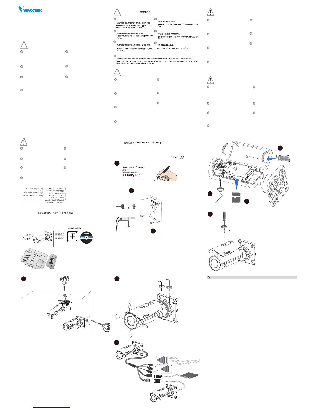
Hardware Installation / Hardwareinstallation / Hardware installeren
硬體架設 /
ハードウェア ・ インストレーション
硬件安装 /
Installation du matériel / Instalacao de Hardware / Instalación del hardware
Instalacja sprzętu / Монтаж оборудования / Instalace hardwaru
Installazione hardware / Donanım Montajı / Installation av hårdvara
Installation af hardware / Pemasangan Perangkat Keras
icro
M
icro
TM
Au+
Au-
MIC P
MIC N
DO+
DO-
DI+
DI-
icro
The yellow LAN port can only be used to connect to another camera (PoE output). Please do
not connect the yellow LAN port to a PC or switch LAN port.
De gele LAN-poort kan uitsluitend worden gebruikt om verbinding te maken met een andere
camera (PoE-uitvoer). Sluit de gele LAN-poort niet aan op een pc of LAN-poort van ee switch.
Der gelbe LAN Port kann nur für die Verbindung mit einer anderen Kamera (PoE Ausgang)
genutzt werden. Bitte verbinden Sie den gelben LAN Port nicht mit einem PC oder Switch LAN
Port.
黃色的 LAN 連接埠只能用於連接其他 攝影機 (PoE 輸出 )。請勿將黃色的 LAN 連接埠連接至個
人電腦或交換器的 LAN 連接埠。
黄色の LAN ポートは別の カメラの接続専用です(PoE 出力)。黄色の LAN ポートを PC やス
イッチの LAN ポートに接続しないでください。
黄色 LAN 端口仅可用于连接其他 摄像头(PoE 输出)。请勿将 LAN 端口连接电脑或交换机 LAN
端口。
Le port LAN jaune peut uniquement être utilisé pour connecter un autre appareil photo (sortie
PoE). Ne pas connecter le port LAN jaune à un PC ou à un port LAN de commutateur.
El puerto LAN amarillo sólo puede usarse para conectarse a otra cámara (salida PoE). No
conecte el puerto LAN amarillo a un PC o al puerto LAN de un switch.
A porta de LAN amarela só pode ser usada para conectar outra câmera (saída de PoE). Não
conecte a porta LAN amarela a um computador ou porta LAN de comutador.
Żółte złącze LAN można wykorzystać wyłącznie do podłączenia kolejnej kamery (wyjście
PoE). Nie należy podłączać żółtego złącza LAN do komputera lub złącza LAN przełącznika
sieciowego.
Žlutý port LAN je možné používat pouze pro připojení další kamery (vstup PoE). Nepřipojujte
žlutý port LAN k počítači nebo portu přepínače sítě LAN.
Желтый порт LAN может использоваться только для подключения к другой камере (выход
PoE). Не подключайте этот порт к ПК или порту LAN коммутатора.
La porta LAN gialla può essere usata solo per il collegamento con un altra telecamera (uscita
PoE). Non collegare la porta LAN gialla ad un PC o a una porta switch LAN.
Den gula LAN-porten kan endast användas för att ansluta till en annan kamera (PoE-utgång).
Anslut inte den gula LAN-port till en PC eller LAN-växelport.
Sarı LAN bağlantı noktası yalnızca başka bir kameraya bağlamak için kullanılabilir (PoE
çıkış). Lütfen sarı LAN bağlantı noktasını bir kişisel bilgisayara bağlamayın veya LAN bağlantı
noktasını değiştirmeyin.
Den gule LAN-port kan kun bruges for tilslutning til et andet kamera (PoE-output). Tilslut ikke
den gule LAN-port til en PC eller en switchs LAN-port.
Port LAN berwarna kuning hanya dapat digunakan untuk menghubungkan ke kamera lain (output
PoE). Jangan hubungkan port LAN berwarna kuning ke PC atau port LAN switch.
IB836B-HRT
IB836B-HRF3
IB8382-RF3
يمكن استخدام منفذ LAN الأصفر فقط للتوصيل بكاميرا أخرى (خرج PoE) يرجى عدم توصيل منفذ
LAN الأصفر بجهاز كمبيوتر أو تبديل منفذ LAN.
0002D10766AD
XXXXXX
1
2
3
4
5
6
7
8
9
10
Page 4
VIVOTEK INC.
6F, No.192, Lien-Cheng Rd., Chung-Ho, New Taipei City, 235, Taiwan, R.O.C.
VIVOTEK USA, INC.
2050 Ringwood Avenue, San Jose, CA 95131
VIVOTEK Europe
Randstad 22-133, 1316BW Almere, The Netherlands
All specications are subject to change without noice.
Copyright © 2015 VIVOTEK INC. All rights reserved.
0002D1730202
00-02-D1-73-02-02 192.168.5.151 FD8168
IW2
Browser
LAN
What Is Covered : This warranty covers any hardware defects in materials or
workmanship, with the exceptions stated below.
How Long Coverage Lasts: This warranty lasts fo r THIRTY-SIX MONTHS from
the date of purchase by the original end-user customer.
What Is Not Covered : This warranty does not cover cosmetic damage or any
other damage or defect caused by abuse, misuse, neglect, use in violation of
instructions, repair by an unauthorized third part y, or an act of God. Also, if serial
numbers have been altered, defaced, or removed. Furthe r, consequential and
incidental damages are not recoverable under this warranty.
What VIVOTEK Will Do: VIVOTEK will, in our sole discretion, repair or replace
any product that proves to be defective in material or workmanship. Any repair or
replaced part of the product will receive a THREE-MONTH warranty extension.
How To Get Service:
Contact our authorized distributors in your region. Please
check our website (www .vivotek.com) for the information of an authorized
distributor near you.
Your Rights: SOME STATES DO NO T ALLOW EXCLUSION OR LIMIT ATION
OF CONSEQUENTIA L OR INCIDENTAL DAMAGES, SO THE ABOVE EXCL USION OR LIMI TATION MAY NO T APPLY TO
YOU. THIS W ARRANTY GIVES
YOU SPECIFIC LEGAL RIGHTS, AND YOU MAY ALSO HAVE OTHER RIGHTS
WHICH VARY FROM STATE TO STATE.
1. Proof of the date of purchase is required. In the event you can not render such
document, warranty will commence from the date of manufacture.
2. Cosmetic damage will only be covered by this warranty if such damage has
been existed at the time of purchase.
VIVOTEK INC.
6F, No. 192, Lien-Cheng Rd., Chung-Ho,
Taipei County, Taiwan.
www.vivotek.com
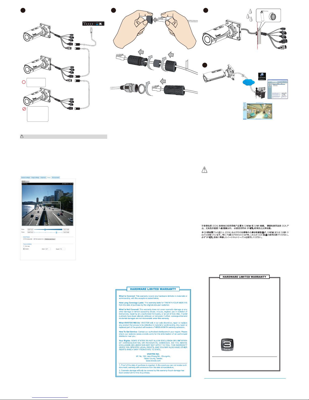
Perform the Auto Focus function for best image. However, if you have cascaded cameras, do
this one by one. Do not perform this function simultaneously on multiple cameras because the
motorized lens also consume considerable power, and may cause the last camera on the line to
hang.
使用自動對焦功能以達到最佳影像效果。 但若您將多台攝影機串接,請在各攝影機中逐一執行上
述功能。 請勿同時於多台攝影機上使用自動對焦功能,因為馬達驅動鏡頭會消耗大量電力,且可
能導致線路上的最後一台攝影機停擺。
执行自动对焦功能可以获得最佳的图像。 不过,如果您有级联的摄像头,请逐一执行此操作。 请
勿同时对多个摄像头执行此功 能,因为电动镜头也会消耗不少 电能,可能会导致线路中最后一 个
摄像头挂起。
最高の画質を得るためにオートフォーカス機能を実行します。 ただし、カスケード接続されたカメラをご
利用の場合はこれを 1 つずつ実行してください。 複数のカメラでこの機能を同時に実行しないでくださ
い。電動レンズが相当量の電力を消 費するため、ライン上の最後のカメ ラがハングアップすることがあ
ります。
Exécutez la fonction Mise au point automatique pour optimiser l'image. Toutefois, si vous
avez des caméras montées en cascade, faites-le une par une. N'effectuez pas cette fonction
simultanément sur plusieurs caméras car l'objectif motorisé consomme également énormément
d'énergie et peut entraîner l'interruption de la dernière caméra sur la ligne.
Realiza la función de autoenfoque para obtener una mejor imagen. Por otro lado, si las cámaras
están en cascada, hágalo una a una. No realice esta función a la vez en múltiples cámaras
porque los objetivos motorizados también consumen energía y pueden provocar que la última
cámara de la línea se bloquee.
Führen Sie die Autofokus Funktion für das beste Bild aus. Wenn Sie allerdings Kameras in
Reihe haben, führen Sie dies einzeln nacheinander aus. Führen Sie diese Funktion nicht
gleichzeitig auf mehreren Kameras aus, da das motorisierte Objektiv viel Strom benötigt und die
letzte Kamera in der Reihe hängen könnte.
Realize a função de foco automático para obter a melhor imagem. No entanto, se você possui
câmeras em sequência, faça isso com uma a uma. Não realize essa função simultaneamente
em múltiplas câmeras, uma vez que as lentes motorizadas também consomem carga
considerável e podem fazer com que a última câmera na lente seja desconectada.
Esegui la funzione Auto Focus per ottenere l'immagine migliore. Tuttavia, se avete
telecamere in cascata, eseguire l'operazione una alla volta. Non eseguire questa funzione
contemporaneamente su più telecamere, poiché le lenti motorizzate consumano molta corrente
e l'ultima telecamera sulla linea potrebbe rimanere bloccata.
En iyi görüntü için Otomatik Odak işlevini gerçekleştirin. Ancak, kademeli kameralarınız
varsa bunu tek tek yapın. Motorlu mercek de önemli ölçüde güç tükettiğinden ve hattaki son
kameranın askıda kalmasına neden olabileceğinden, bu işlevi birden fazla kamerada aynı anda
gerçekleştirmeyin.
Aby uzyskać lepszy obraz, skorzystaj z funkcji Auto Focus (Automatycznej regulacji ostrości).
Jeżeli jednak kamery ustawione są kaskadowo, należy użyć tej funkcji kolejno dla każdej
kamery. Nie używaj funkcji równocześnie dla kilku kamer, ponieważ znaczne zużycie energii
przez napęd obiektywu może spowodować zawieszenie się ostatniej kamery w linii.
Выполните автофокусировку для получения наилучшего качества изображения. Однако,
если камеры подключены каскадно, эту операцию следует выполнять поочередно для
каждой камеры. Не следует выполнять эту операцию для нескольких камер одновременно,
так как моторизованные объективы потребляют значительную мощность, и это может
привести к зависанию последних камер в цепочке.
Pro dosažení nejlepšího obrazu použijte funkci Auto Focus. Pokud máte kaskádovité kamery,
proveďte to pro jednu po druhé postupně. Nepoužívejte tuto funkci současně na několika
kamerách, protože motorizované objektivy spotřebovávají značnou energii a to může způsobit
zaseknutí poslední kamery.
Utför autofokusfunktionen för bästa bildkvalitet. Om du har kaskaderade kameror ska du
göra detta ett i taget. Utför inte den här funktionen samtidigt på era kameror, eftersom den
motoriserade linsen även förbrukar mycket ström och detta kan göra att den sista kameran i
linjen hänger sig.
Gebruik de Auto Focus-functie voor optimaal beeld. Als u echter meerder verbonden camera's
heeft, dit één voor één doen. Deze functie niet gelijktijdig op meerdere camera's gebruiken
omdat de gemotoriseerde lens ook aanzienlijke stroom verbruikt, en storing kan veroorzaken bij
de laatste aangesloten camera.
Udfør autofokusering for det bedste billede. Hvis du imidlertid har kaskadekoblede kameraer,
gør det for et ad gangen. Udfør ikke denne funktion samtidigt for flere kameraer, fordi de
motoriserede linser trækker en betydelig strøm, hvorved de sidste kamera i kæden kan hænge.
Jalankan fungsi Fokus Otomatis untuk mendapatkan gambar terbaik Namun, jika Anda
telah menyalurkan kamera, lakukan hal ini satu per satu. Jangan jalankan fungsi ini secara
bersamaan pada beberapa kamera karena lensa bermotor juga mengonsumsi daya yang cukup
besar, dan dapat menyebabkan kamera terakhir di saluran menjadi macet.
قم بإجراء وظيفة التركيز التلقائي للحصول على أفضل صورة. ومع ذلك، إذا كانت لديك كاميرات متتالية، فافعل هذا واحدة بواحدة.
لا تقم بإجراء هذه الخاصية في نفس الوقت على كاميرات متعددة لأن العدسة الآلية أيضًا تستهلك قدرًا كبيرًا من الطاقة، وقد يؤدي
إلى توقف الكاميرا الأخيرة على الخط.
e t .
3.5 ~ 6mm
Many copper coated aluminum (CCA) and other non-standard conductors cabling products are
masqueraded as CAT5E or CAT6 cables. Please avoid using these CCA products especially
when cascading PoE cameras. It is a must to use Ethernet cables compliant with the 3P/ETL
standard.
Viele Verkabelungsprodukte mit Kupferbeschichtetem Aluminium (CCA) und anderen nicht
Standardleitern werden als CAT5E oder CAT6-Kabel ausgegeben. Vermeiden Sie bitte die
Verwendung dieser CCA Produkte vor allem bei der Kaskadierung von PoE-Kameras. Es ist ein
Muss, mit dem 3P/ETL-Standard kompatible Ethernetkabel zu verwenden.
Veel koper gecoat aluminium (CCA) en andere niet-standaard geleidende kabelproducten
doen zich voor als CAT5E of CAT6 kabels. Vermijd gebruik van deze CCA-producten, vooral bij
gebruik van trapsgewijze PoE camera's. Het is een must om Ethernet-kabels te gebruiken die
compatibel zijn met de 3P/ETL-standaard.
De nombreux produits de câblage à conducteurs en aluminium revêtu de cuivre (CCA) et autres
conducteurs non standard sont masqués en CAT5E ou CAT6. Evitez d'utiliser ces produits CCA
surtout lors de la mise en cascade de caméras PoE. Il est bien meilleur d'utiliser des câbles
Ethernet conformes à la norme 3P/ETL.
許多銅包鋁 (CCA) 以及其他不符標準的導體佈線產品會偽裝為 CAT5E 或 CAT6 纜線。 請避免使
用此類 CCA 產品,尤其是當串接 PoE 攝影機時更不該使用。 請務必使用符合 3P/ETL 標準的乙
太網路線。
多くの銅被覆アルミニウム (CCA) およびその他標準外の導体配線製品が、CAT5E または CAT6 ケ
ーブルを装っています。 特に PoE カメラのカスケード時、これらの CCA 製品の使用を避けてください。
必ず 3P/ETL 規格に準拠したイーサネットケーブルを使用してください。
许多铜包铝 (CCA) 和其他非标准导线产品冒充 CAT5E 或 CAT6 线缆。 请避免使用这些 CCA 产
品,尤其是在级联 PoE 摄像头时。 必须使用符合 3P/ETL 标准的以太网电缆。
WARNING:
警告:警告:警告:
ATTENTION ! ADVERTENCIA:
WARNUNG: ATENÇÃO! AVVERTENZA:
UYARI: OSTRZEŻENIE:
ВНИМАНИЕ!
VÝSTRAHA!
VARNING:
WAARSCHUWING!
ADVARSEL:
PERINGATAN:
تحذير:
Muchos cables conductores recubiertos de aluminio (CCA) y otros no estándares están
enmascarados como cables CAT5E o CAT6. Evite utilizar estos productos CCA, especialmente
cuando conecte cámaras PoE en cascada. Se deben usar cables Ethernet compatibles con el
estándar 3P/ETL.
Muitos condutores de alumínio revestido a cobre (CCA) e outros produtos de cabeamento
não padrão são mascarados como cabos CAT5E ou CAT6. Evite usar esses produtos
CCA especialmente ao encaminhar câmeras PoE. É obrigatório usar cabos Ethernet em
conformidade com o padrão 3P/ETL. .
Molti prodotti di cablaggio in alluminio rivestiti di rame (CCA) e altri conduttori non standard
sono mascherati da cavi CAT5E o CAT6. Evitate l'uso di questi prodotti CCA specialmente per
l'installazione a cascata di telecamere PoE. È obbligatorio l'uso di cavi Ethernet conformi allo
standard 3P/ETL.
Çoğu bakır kaplama alüminyum ve diğer standart olmayan iletken kablo tesisatı ürünleri CAT5E
veya CAT6 kablosu olarak tanıtılır. Özellikle PoE kameraları kademeli olarak dizerken lütfen bu
bakır kaplama alüminyum ürünleri kullanmaktan kaçının. Mutlaka 3P/ETL standardıyla uyumlu
Ethernet kabloları kullanılmalıdır.
Wiele powlekanych miedzią przewodników aluminiowych (CCA) oraz innych niestandardowych
przewodników wykorzystywanych do produkcji kabli jest sprzedawanych w produktach
nalnych jako kable CAT5E lub CAT6. Prosimy unikać używania takich kabli CCA szczególnie
w przypadku kaskadowego podłączenia kamer zasilanych przez Ethernet (PoE). Jako warunek
konieczny należy korzystać z kabli Ethernet, zgodnych ze standardem 3P/ETL.
Многие кабели с алюминиевыми проводниками (CCA), имеющими медное покрытие, а
также с другими нестандартными проводниками, имитируют кабели категории CAT5E
или CAT6. Избегайте использования подобных кабелей CCA, особенно при каскадном
подключении камер с питанием PoE. Для камер требуется использовать Ethernet-кабели,
отвечающие стандарту 3P/ETL.
Mnoho hliníkových vodičů povlakovaných mědí (CCA) a dalších nestandardních vodičů v
kabelech je prohlašováno za kabely třídy CAT5E nebo CAT6. Nepoužívejte takové produkty
CCA obzvláště při kaskádování kamer PoE. Musíte používat kabely Ethernet ve shodě s normou
3P/ETL.
Många kopparbelagda aluminium- (CCA) och andra icke-standardiserade ledare och
kablageprodukter utger sig att vara CAT5E- eller CAT6-kablar. Undvik att använda dessa CCAprodukter, särskilt vid kaskadering av PoE-kameror. Det är ett måste att använda Ethernet-
kablar som är kompatibla med 3P/ETL-standarden.
Mange kabelprodukter med kobbercoatede aluminiumsledere (CCA) og andre ikke-
standardiserede ledere udgiver sig for at være CAT5E- eller CAT6-kabler. Undgå at bruge disse
CCA-produkter, specielt ved kaskadekoblede PoE-kameraer. Det er et krav at bruge Ethernet-
kabler, der opfylder 3P/ETL-standarden.
Banyak aluminium berlapis tembaga (CCA) dan produk kabel konduktor non-standar lainnya
yang merupakan kabel CAT5E atau CAT6 palsu. Harap hindari penggunaan produk CCA ini
terutama ketika menyalurkan kamera PoE. Harus menggunakan kabel Eternet sesuai dengan
standar 3P/ETL.
العديد من الموصلات الألمونيوم المطلية بالنحاس وغيرها من منتجات كابلات التوصيل غير القياسية تأتي متخفية على أنها
كابلات CAT5E أو CAT6. يرجى تجنب استخدام منتجات الألمونيوم المطلي بالنحاس هذه خاصة عند وضع سلسلة متتالية من كاميرا
PoE. يجب استخدام كابلات إيثرنت متوافقة مع معيار 3P/ETL.
11 12 13
IB836B-H(R)F3, IB8382-(R)F3, IB836B-EHF3,
IB836B-EF3,
IB836B-H(R)T, IB836B-EHT, IB8382-ET,
IB8382-(R) T
1 234
1 2 3 4
LAN
PoE
UPLINK
PoE
ON
OFF
4xFE PoE + 1xFE Switch
UPLINK
POWER
ON
AW-FED-0500-120
100m
100m
100m
IB836B-HRT
IB836B-HT
IB8382-RF3
IB836B-HRF3
IB836B-EHT
IB836B-EHF3
IB836B-HF3
IB8382-F3
IB836B-HRT
IB8382-RF3
IB836B-HRF3
IB8382-ET
IB8382-EF3
14
Page 5
User’s Manual
Outdoor • Day & Night • 30M IR • Cable Management
Bullet
Network Camera
IB8382-(R)T/(R)F3/ET/EF3
IB836B-H(R)T/EHT/H(R)F3/EHF3
Rev. 1.1
Page 6

VIVOTEK
2 - User's Manual
Table of Contents
Overview
..............................................................................................................................................................
3
Revision History ...............................................................................................................................................3
Read Before Use ..............................................................................................................................................4
Package Contents ............................................................................................................................................4
Symbols and Statements in this Document ......................................................................................................4
Physical Description .........................................................................................................................................5
Repeater Model (
IB8382-RF3/RT, IB836B-HRT/HRF3.
) Cascade Connections ........................................7
Hardware Installation ........................................................................................................................................9
Network Deployment ......................................................................................................................................16
Software Installation .......................................................................................................................................19
Ready to Use ..................................................................................................................................................20
Auto Focus .....................................................................................................................................................21
Accessing the Network Camera
....................................................................................................................
22
Using Web Browsers ......................................................................................................................................22
Using RTSP Players .......................................................................................................................................25
Using 3GPP-compatible Mobile Devices ........................................................................................................26
Using VIVOTEK Recording Software .............................................................................................................27
Main Page
.........................................................................................................................................................
28
Client Settings
..................................................................................................................................................
33
Conguration
....................................................................................................................................................
38
System > General settings .............................................................................................................................39
System > Homepage layout ..........................................................................................................................41
System > Logs ...............................................................................................................................................44
System > Parameters ....................................................................................................................................46
System > Maintenance ...................................................................................................................................47
Media > Image .............................................................................................................................................51
Media > Video ................................................................................................................................................64
Media > Video ................................................................................................................................................66
Media > Audio.................................................................................................................................................72
Network > General settings ............................................................................................................................73
Network > Streaming protocols ....................................................................................................................81
Network > SNMP (Simple Network Management Protocol) ...........................................................................90
Security > User accounts ...............................................................................................................................91
Security > HTTPS (Hypertext Transfer Protocol over SSL) .................................................................92
Security > Access List ..................................................................................................................................99
PTZ > PTZ settings ......................................................................................................................................104
Event > Event settings..................................................................................................................................108
Applications > Motion detection....................................................................................................................122
Applications > DI and DO ...........................................................................................................................125
Applications > Tampering detection .............................................................................................................126
Applications > Audio detection ...................................................................................................................127
Applications > Package management - a.k.a., VADP (VIVOTEK Application Development Platform) .......129
Recording > Recording settings ..................................................................................................................132
Local storage > SD card management .........................................................................................................137
Page 7

VIVOTEK
User's Manual - 3
Local storage > Content management ..................................................................................................... 138
Appendix
...................................................................................................................................................
141
URL Commands for the Network Camera ................................................................................................ 141
Technical Specications ...........................................................................................................................233
Technology License Notice .......................................................................................................................234
Electromagnetic Compatibility (EMC) .......................................................................................................235
Overview
VIVOTEK IB836B and 8382 series are stylish, bullet-style network cameras designed for
diverse outdoor applications. Equipped with a 2MP sensor enabling viewing resolution of
1920x1080 at a smooth 30 fps, the camera series is all-in-one outdoor camera capable of
capturing high quality and high resolution, especially in low light environment. In addition
to applying VIVOTEK’s notable bandwidth solution in Smart Stream and 3DNR, the
IB836B and 8382 -T/-RT models are also designed with smart focus system to assit focus
adjustment more efciently.
To meet more outdoor applications and ease cable deployment, IB836B and 8382 “-R”
models are the first network camera designed with embedded extender to allow PoE
input and PoE output. Users can implement a total PoE solution perfectly. Incorporating a
number of advanced features standard for VIVOTEK cameras, the IB836B and 8382 series
are the ideal solutions for your outdoor surveillance needs.
Revision History
■ Rev. 1.0: Initial release.
■ Rev. 1.0: Updated URL commands to rev. 1.4b.
Page 8

VIVOTEK
4 - User's Manual
Read Before Use
VIVOTEK’s IB8382 is a series of economic professional outdoor bullet network cameras in
VIVTOTEK’s 5MP Lite series which offer up to 15 fps at 5-Megapixel or 30 fps at 1080p resolution
at a competitive price. Equipped with a new high resolution image sensor, different from other 5MP
cameras, the IB8382 series provides sharper image quality and ner detail at a cost-effective price.
And with powerful 3D Noise Reduction technology and Smart Stream technology the IB8382 series
can also optimize resolution for a desired object or area to maximize efciency of bandwidth usage.
VIVOTEK’s IB836B-H is a series of stylish, bullet-style network cameras designed for diverse
outdoor applications and offering a complete range of options. Equipped with a 2MP Full HD sensor
enabling viewing resolution of 1920x1080 at a smooth 30 fps, the IB836B-H series is an all-in-one
outdoor camera capable of capturing high quality and high resolution video up to 2 Megapixel with
WDR and SNV technology, no matter whether in high contrast or in low light environments.
To create the perfect focus required to reap the benets of higher resolutions, VIVOTEK’s IB8382
series provides the options of both xed focus, used for simple operation without electrical power,
and remote focus with built-in stepping motors and P-iris for precise adjustment remotely.
To provide higher resolution in outdoor and harsh environments, this series is also armed with
IP66-rated housing to help the camera body withstand rain, dust and high pressure water jets from
any direction, while its IK10-rated housing provides protection against acts of vandalism or other
impacts. Additionally, a wide operating temperature range further improves the IB8382-EF3 and
IB8382-ET’s performance and reliability in extremely cold or warm weather, even when using PoE.
With the highly exible VADP (VIVOTEK Application Development Platform), users can extend the
features of this series by adding third-party applications for the IB8382-F3, IB8382-EF3, IB8382-T,
and IB8382-ET. Thus the IB8382 series is not only equipped with multiple focusing methods and
wide temperature range options, is but ideal for a wide variety of applications.
Finally, a wide operating temperature range further enhances the IB836B-H’s performance
and reliability in extremely cold or hot weather, even when using PoE. When choosing
VIVOTEK IB836B-H series, customers will be offered four options: the IB836B-HF3,
IB836B-EHF3, IB836B-HT, and IB836B-EHT. Different options can be chosen based on
the requirements of your application, such as focusing method or operating environment
temperature.
Package Contents
■ IB836B-H(R)T/EHT/H(R)F3/EHF3, IB8382-(R)T/(R)F3/ET/EF3.
■ L-type T8 anti-tamper key wrench, desiccant bag, screws
■ Waterproof Ethernet cable housing
■ Software CD
■ Quick Installation Guide & alignment sticker
* T8 key wrench is also used for the hex socket screw on the camera bracket.
Page 9
VIVOTEK
User's Manual - 5
Symbols and Statements in this Document
i
INFORMATION: provides important messages or advices that might help prevent
inconvenient or problem situations.
NOTE: Notices provide guidance or advices that are related to the functional integrity of
the machine.
Tips: Tips are useful information that helps enhance or facilitae an installation, function,
or process.
WARNING: or IMPORTANT:: These statements indicate situations that can be
dangerous or hazardous to the machine or you.
Electrical Hazard: This statement appears when high voltage electrical hazards might
occur to an operator.
Physical Description
Front Panel
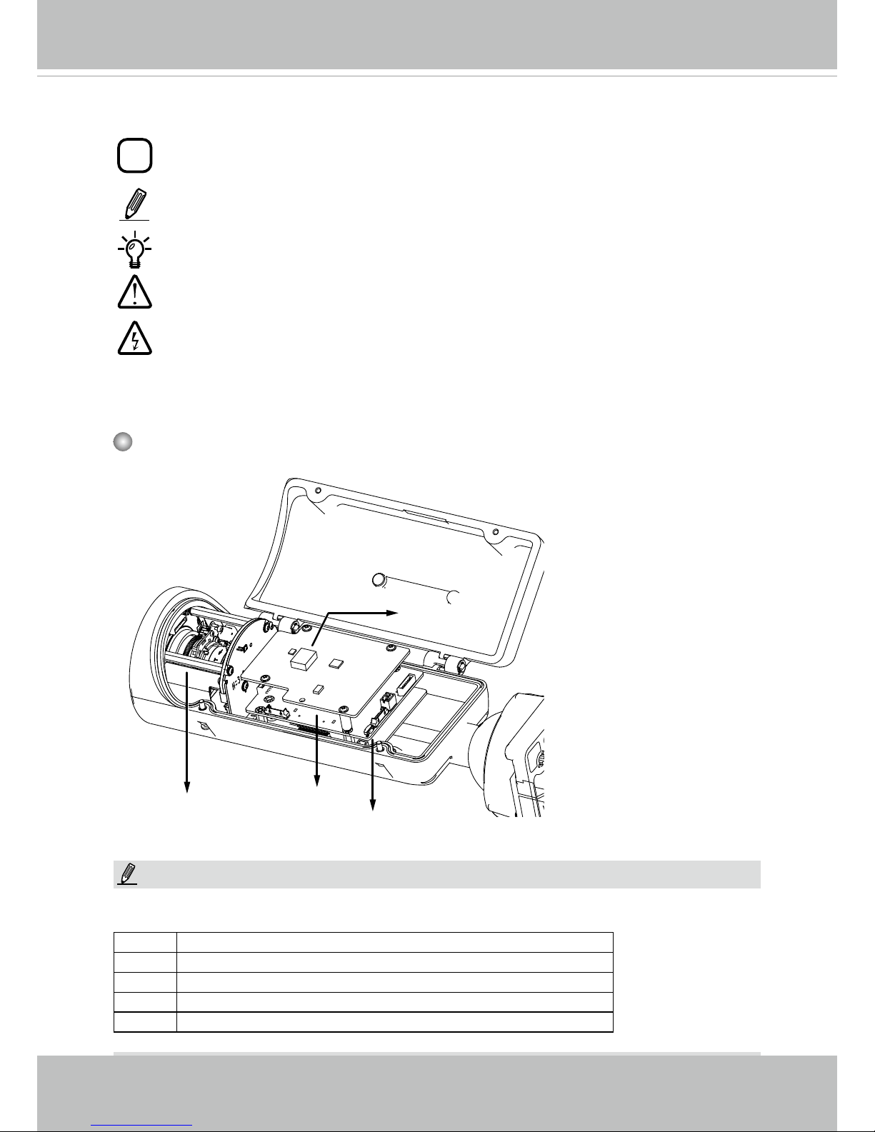
Motorized or
xed lens
The T and RT models have auto-focus motorized lens. Some of the sufx syntax used in
model naming are listed below:
E w/ heater for extreme weather
Fx Focal length w/ number
T w/ Remote focus lens
R w/ PoE repeater
H w/ High Dynamic Range functionality
NOTE:
Reset Button
SD/SDHC/SDXC
Card Slot
PoE daughterboard
Page 10
VIVOTEK
6 - User's Manual
Connectors
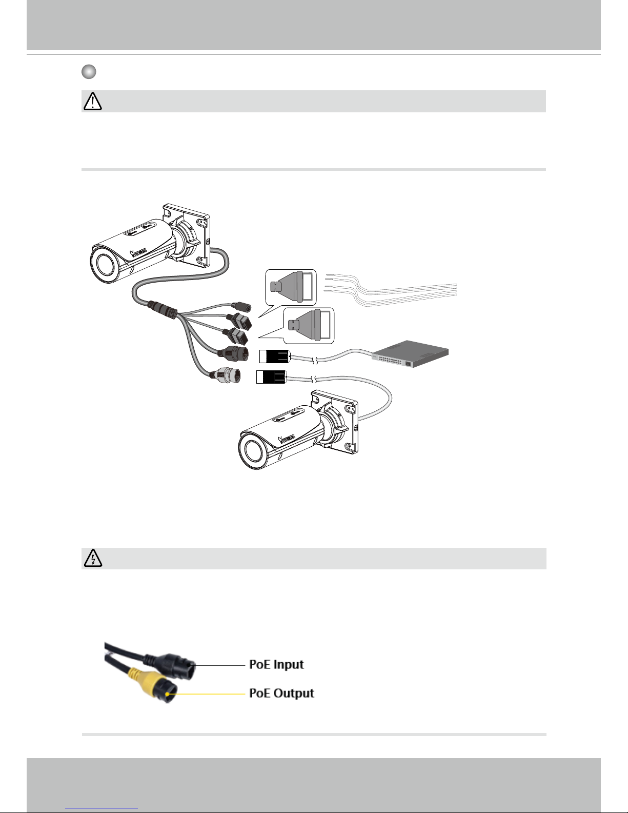
The second LAN port (PoE out, yellow) is available on the IB836B-HRT, IB836B-HRF3,
and IB8382-RF3. The R models come without the DC connector.
WARNING:
The yellow LAN port (PoE output) can only be used to connect to another IB836B/8382
camera. Please do not connect the yellow LAN port to a PC or switch LAN port. The high
voltage can damage the LAN port circuits.
Au+
Au-
MIC P
MIC N
DO+
DO-
DI+
DI-
icro
General I/O Terminal Block
Ethernet 10/100 RJ45 Plug
•
The "E" models, e.g., IB8382-ET, IB836B-EHT, do not support PoE cascade
connections due to its high power consumption. The "E" models come with embedded
heater for low temperature environments.
IMPORTANT:
R model, e.g., IB836B-HRT.
Page 11
VIVOTEK
User's Manual - 7
Repeater Model (
IB8382-RF3/RT, IB836B-HRT/HRF3.
) Cascade Connections
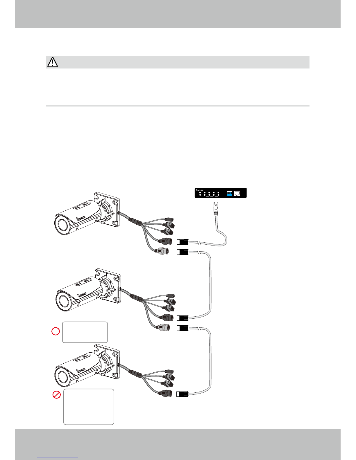
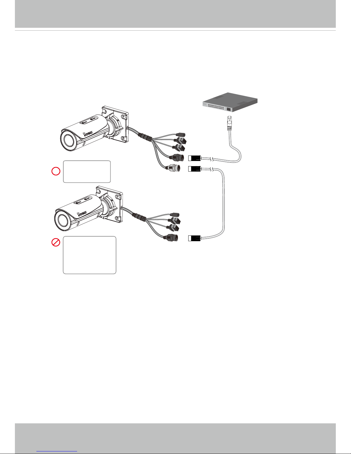
Each camera consumes up to 14.5W power. Up to 2 R model cameras and 1 non-repeater
camera can be cascaded in a conguration with a cabling distance of up to 300 meters.
The precondition is the use of the AE-FED-0500-120 PoE switch, which can deliver more
than 50W of power per port (exceeding the 802.3at specications).
Please use quality cables when cabling over an extended distance. Power loss due to
resistance can occur with low-quality cables.
1 234
1 2 3 4
LAN
PoE
UPLINK
PoE
ON
OFF
4xFE PoE + 1xFE Switch
UPLINK
POWER
ON
AW-FED-0500-120
100m
100m
100m
IB836B-HRT
IB836B-HT
IB8382-RF3
IB836B-HRF3
IB836B-EHT
IB836B-EHF3
IB836B-HF3
IB8382-F3
IB836B-HRT
IB8382-RF3
IB836B-HRF3
IB8382-ET
IB8382-EF3
Many copper coated aluminum (CCA) and other non-standard conductors cabling products
are masqueraded as CAT5E or CAT6 cables. Please avoid using these CCA products
especially when cascading PoE cameras. It is a must to use Ethernet cables compliant
with the 3P/ETL standard.
IMPORTANT:
The IB "E" series (heater models)
can not be applied in the cascade
conguration due to its extra power
consumption.
Page 12
VIVOTEK
8 - User's Manual
Other-brand 802.3at PoE switch
100m
100m
IB836B-HRT
IB836B-HT
IB8382-RF3
IB836B-HRF3
IB836B-EHT
IB836B-EHF3
IB836B-HF3
IB8382-F3
IB8382-ET
IB8382-EF3
When using an ordinary 802.3at PoE switch (30W output per port), up to 1 IB836B-HRT
and 1 IB836B-HT can be cascaded in a conguration with a cabling distance of up to 200
meters.
Please use quality cables when cabling over an extended distance.
The IB "E" series (heater models) can not be applied in the cascade conguration due to
its extra power consumption.
Page 13
VIVOTEK
User's Manual - 9
Hardware Installation
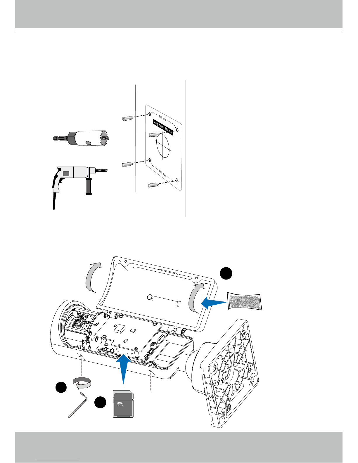
1. Attach the included alignment sticker to a preferred location.
2. Drill holes for mounting screws and a cabling hole.
3. Loosen the anti-tamper screws to open the top cover.
4. Insert an SD card (user-supplied).
5. Replace the desiccant bag whenever you open the top cover. This ensures the
components are free from the moisture.
M
3
4
icro
5
TM
Page 14
VIVOTEK
10 - User's Manual
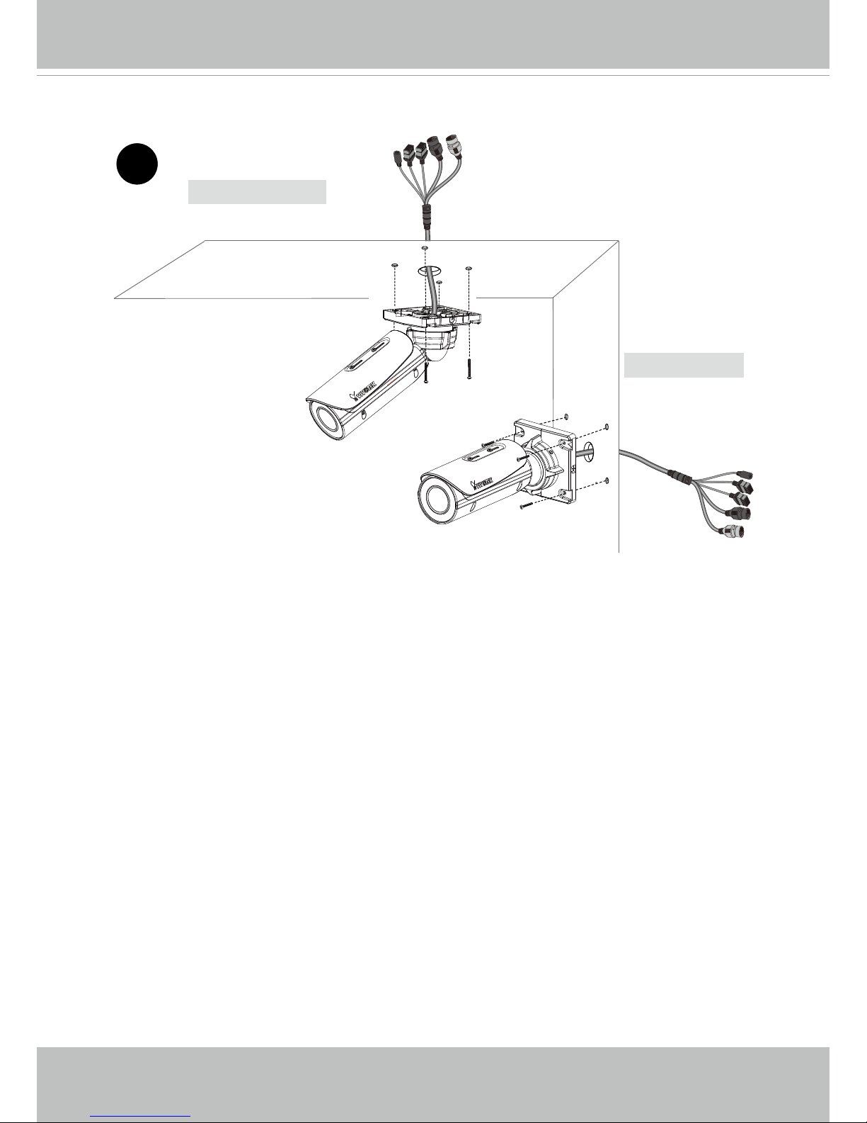
6. Secure the Network Camera to a wall or ceiling.
Wall Mount
Ceiling Mount
6
Page 15
VIVOTEK
User's Manual - 11
3.5 ~ 6mm
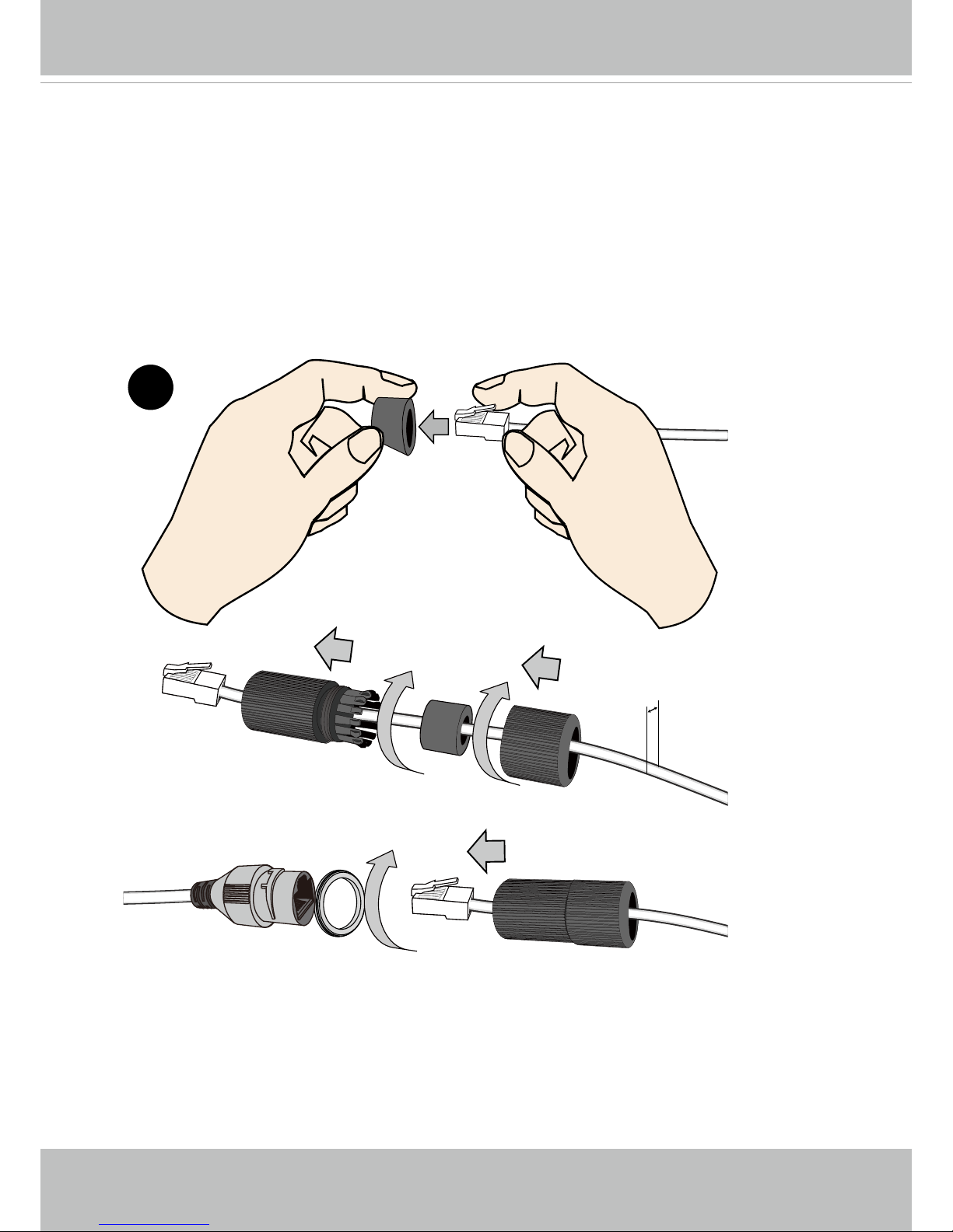
7. When connecting the LAN cable, use the cable housing to make sure the connections
are waterproof.
7-1. Pass the cable through the seal dome, and squeeze the rubber seal through an RJ45
connector.
7-2. You can then pass the cable through the cable gland body.
7-3. Fasten up these components. Make sure enough pressure is exerted on the rubber
seal.
7-4. Connect the Ethernet cable to the RJ45 connector with a seal ring. Fasten the cable
housing.
7
Page 16
VIVOTEK
12 - User's Manual
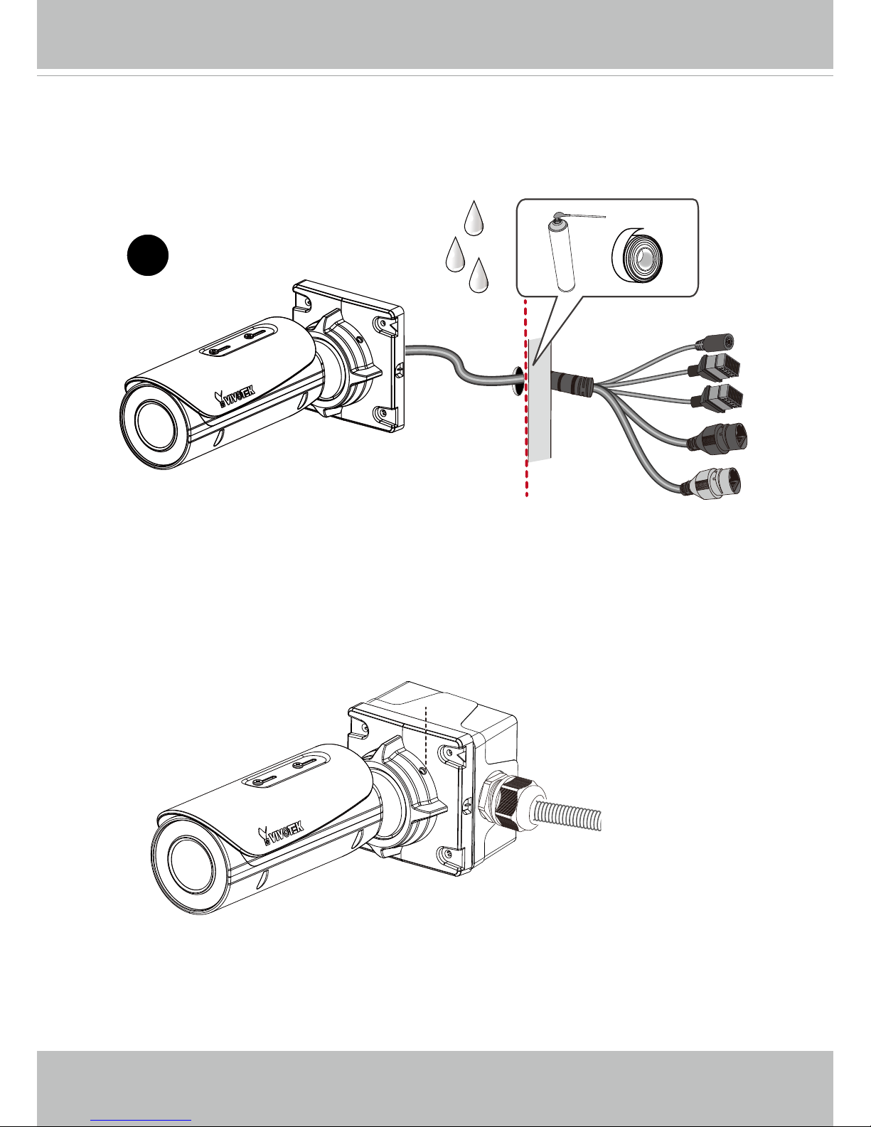
8
8. If your cables pass through a hole on a wall or ceiling, make sure the passage is
waterproof using sealant foam, heat shrink tubing, or putties. Make sure the interfaces,
e.g., DC connectors and terminal connectors, if unused, are also wrapped up using
waterproof putties.
You can also purchase the AM-714 junction box to place all cabling connections within the
protection of the box .
Page 17
VIVOTEK
User's Manual - 13
11. Install the "Installation Wizard 2" software utility on your software CD.
12. The program will search for VIVOTEK Video Receivers, Video Servers or Network Cameras
on the same LAN.
13. Double-click on the camera's MAC address to open a browser management session with
the camera.
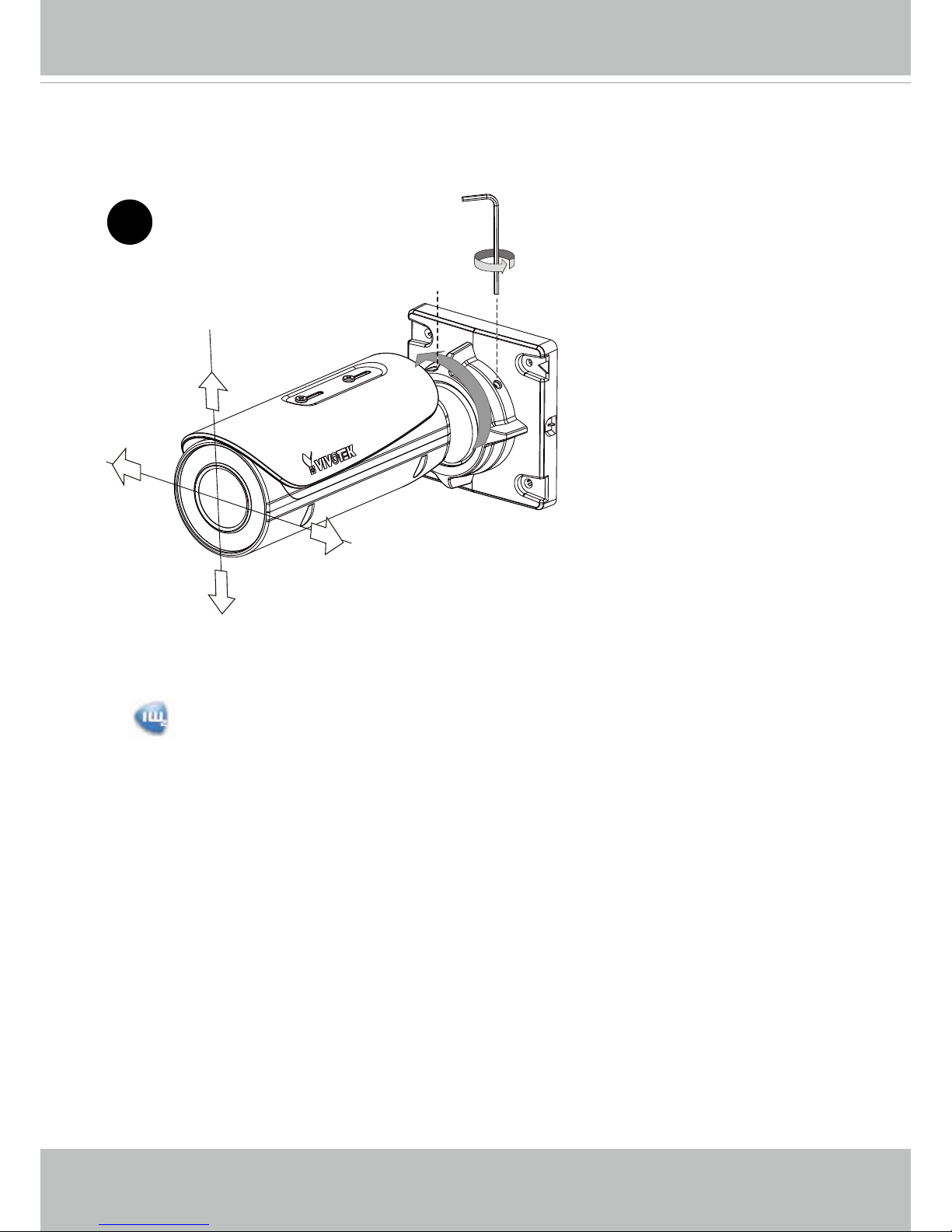
10. Connect the other interfaces, such as I/O wires.
9. Loosen the fastening ring on the mount bracket using a hex wrench, and aim the camera at
the area of your interest. When done, tighten the fastening ring.
Fastening ring
9
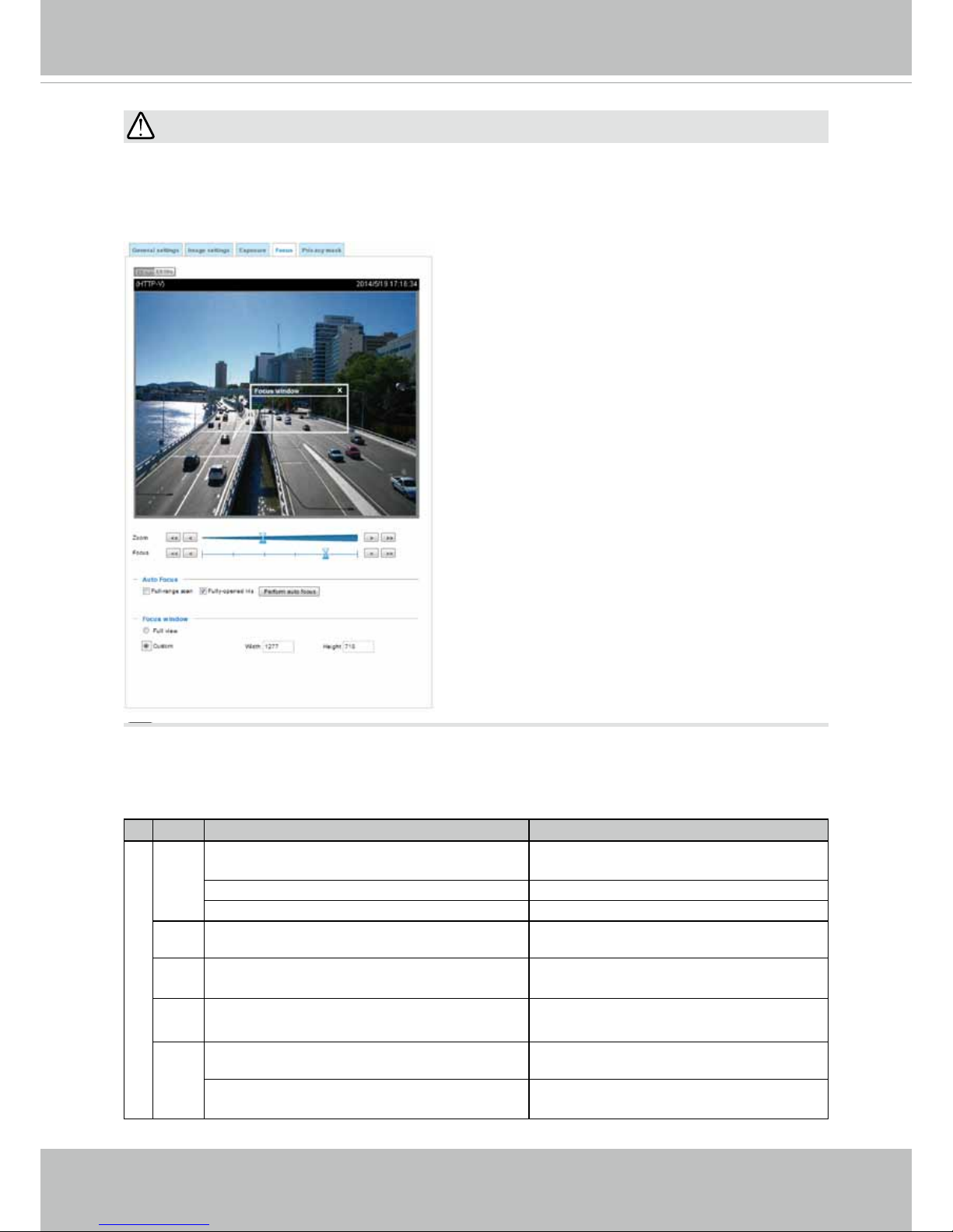
14. With a live view is displayed on your laptop, adjust the zoom and focus to obtain an optimal
image. Check the live view to ensure the image is in focus.
The "T" models comes with motorized focus lens. Use the Auto Focus function in rmware
menu for best image.
Page 18
VIVOTEK
14 - User's Manual
Perform the Auto Focus function for best image. However, if you have cascaded cameras,
do this one by one. Do not perform this function simultaneously on multiple cameras
because the motorized lens also consume considerable power, and may cause the last
camera on the line to hang.
IMPORTANT:
LED Denitions
Item LED status Description
LED De`nitions
1 Steady Red Powered and system booting, or network
failed
Red LED off Power off
Green LED off Network is disconnected
2 Steady Red and Green LED blinks every 1
sec.
Connected to network
3 Green LED blinks every 1 sec. and RED
LED blinks consecutively every 0.15 sec.
Upgrading rmware
4 Green and RED blink every 0.15 sec, Green
and RED light on, then blink again.
Restoring defaults
5 RED LED is on, Green LED blinks and RED
LED is constantly on.
Status after a reset (network connected)
Green and RED LEDs are constantly on. Status after a reset (network
disconnected)
Page 19
VIVOTEK
User's Manual - 15
Hardware Reset
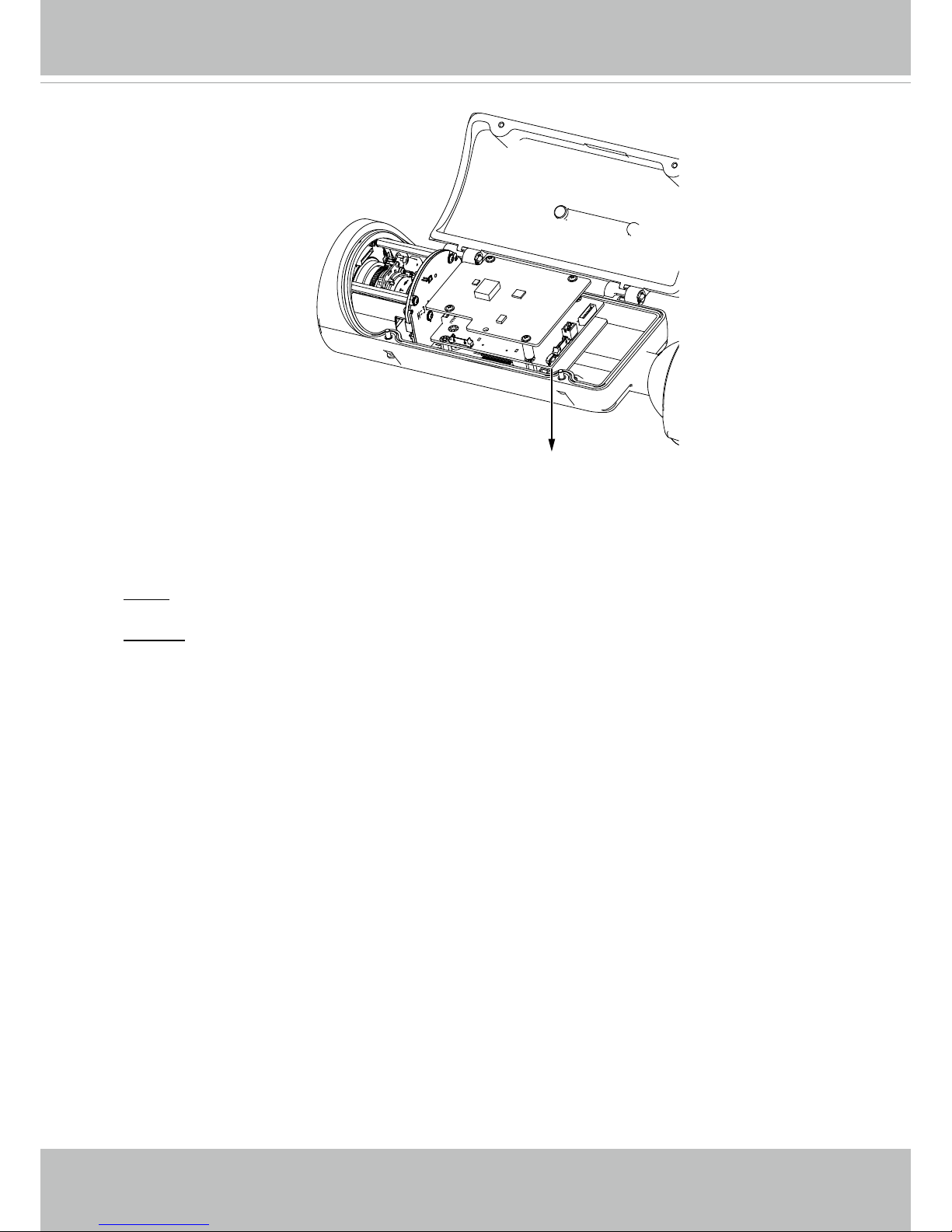
The reset button is used to reset the system or restore the factory default settings.
Sometimes resetting the system can return the camera to normal operation. If the system
problems remain after reset, restore the factory settings and install again.
Reset: Press the recessed reset button. Wait for the Network Camera to reboot.
Restore: Press and hold the reset button until the status LED rapidly blinks. Note that all
settings will be restored to factory default. Upon successful restore, the status LED will
blink green and red during normal operation.
SD/SDHC/SDXC Card Capacity
This network camera is compliant with SD/SDHC/SDXC 16GB / 8GB / 32GB / 64GB and
other preceding standard SD cards.
Reset Button
Page 20
VIVOTEK
16 - User's Manual
Network Deployment
General Connection (PoE)
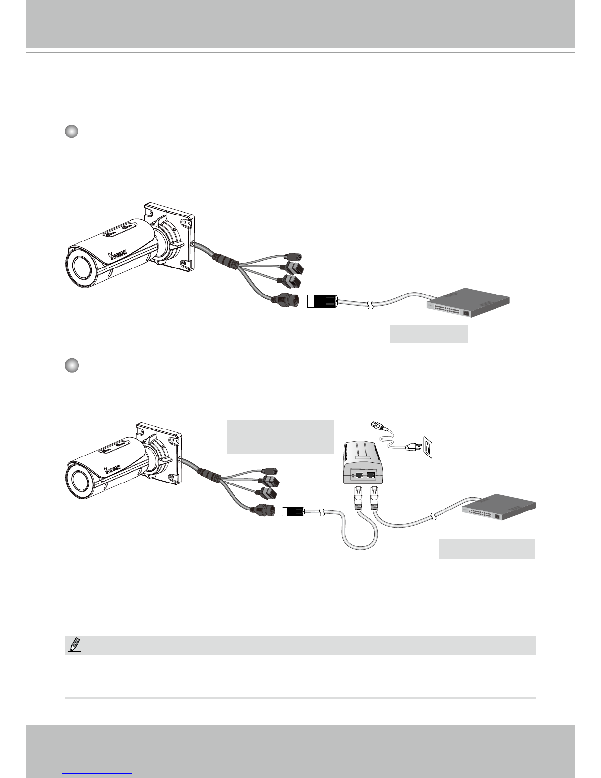
When using a PoE-enabled switch
The Network Camera is PoE-compliant, allowing transmission of power and data via a single Ethernet cable. Follow the below illustration to connect the Network Camera to a PoEenabled switch via Ethernet cable.
PoE Switch
When using a non-PoE switch
Use a PoE power injector (optional) to connect between the Network Camera and a nonPoE switch.
Non-PoE Switch
PoE Power Injector
(optional)
NOTE:
1. The camera is only to be connected to PoE networks without routing to outside plants.
2. For PoE connection, use only UL listed I.T.E. with PoE output.
802.3af
Page 21
VIVOTEK
User's Manual - 17
Internet connection via a router
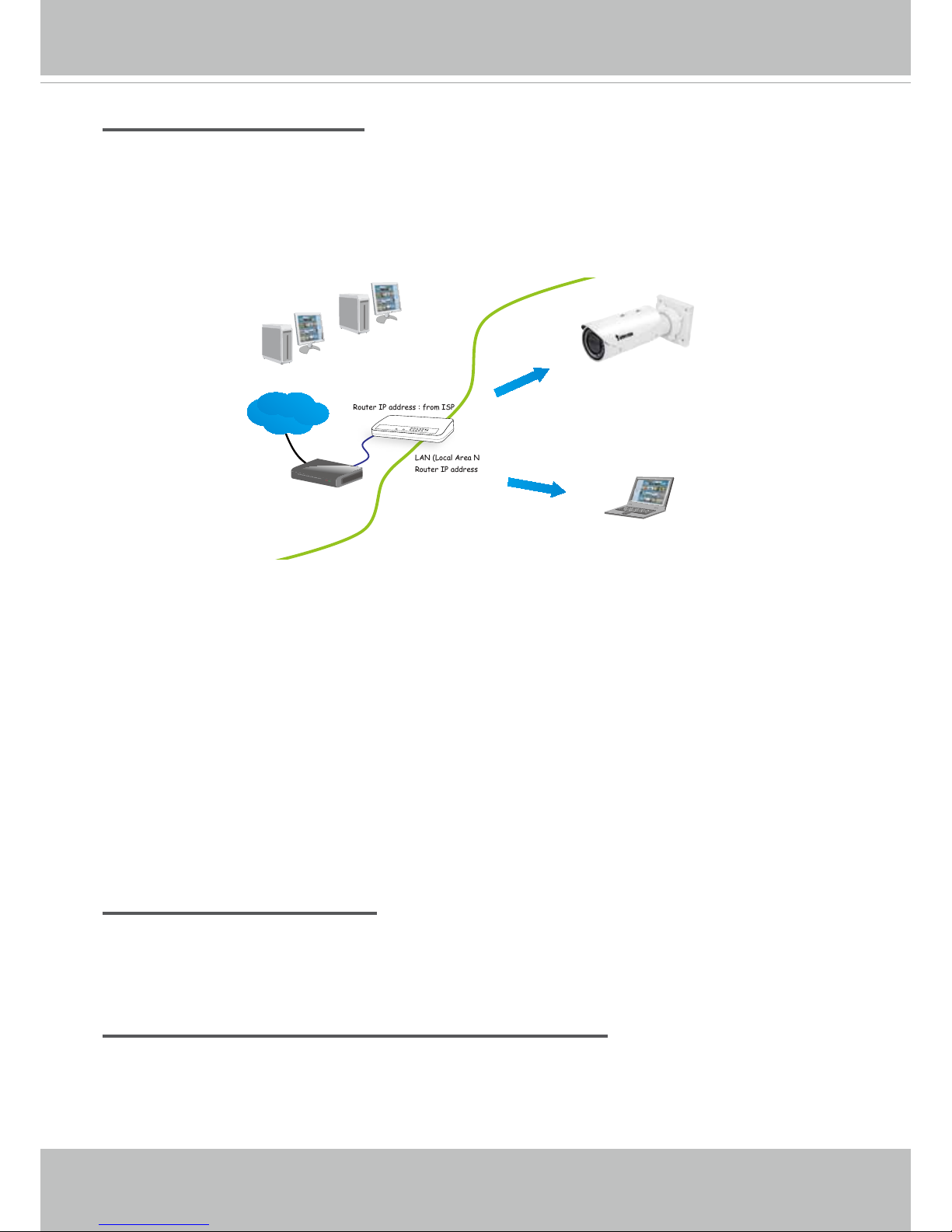
Before setting up the Network Camera over the Internet, make sure you have a router and follow
the steps below.
1. Connect your Network Camera behind a router, the Internet environment is illustrated below.
Regarding how to obtain your IP address, please refer to Software Installation on page 19 for
details.
IP address : 192.168.0.3
Subnet mask : 255.255.255.0
Default router : 192.168.0.1
IP address : 192.168.0.2
Subnet mask : 255.255.255.0
Default router : 192.168.0.1
LAN (Local Area Network)
Router IP address : 192.168.0.1
WAN (Wide Area Network )
Router IP address : from ISP
Cable or DSL Modem
POWER
COLLISION
LINK
RECEIVE
PARTITION
1
2
3
4
5
Internet
2. In this case, if the Local Area Network (LAN) IP address of your Network Camera is
192.168.0.3, please forward the following ports for the Network Camera on the router.
■ HTTP port: default is 80
■ RTSP port: default is 554
■ RTP port for video: default is 5556
■ RTCP port for video: default is 5557
If you have changed the port numbers on the Network page, please open the ports
accordingly on your router. For information on how to forward ports on the router, please refer
to your router’s user’s manual.
3. Find out the public IP address of your router provided by your ISP (Internet Service Provider).
Use the public IP and the secondary HTTP port to access the Network Camera from the
Internet. Please refer to Network Type on page 74 for details.
Internet connection with static IP
Choose this connection type if you are required to use a static IP for the Network Camera.
Please refer to LAN setting on page 73 for details.
Internet connection via PPPoE (Point-to-Point over Ethernet)
Choose this connection type if you are connected to the Internet via a DSL Line. Please refer to
PPPoE on page 74 for details.
Page 22
VIVOTEK
18 - User's Manual
Congure the router, virtual server or rewall, so that the router can forward any data coming into a precongured port number to a network camera on the private network, and
allow data from the camera to be transmitted to the outside of the network over the same
path.
From Forward to
122.146.57.120:8000 192.168.2.10:80
122.146.57.120:8001 192.168.2.11:80
... ...
When properly congured, you can access a camera behind the router using the HTTP
request such as follows: http://122.146.57.120:8000
If you change the port numbers on the Network conguration page, please open the ports
accordingly on your router. For example, you can open a management session with your
router to congure access through the router to the camera within your local network.
Please consult your network administrator for router conguration if you have troubles with
the conguration.
For more information with network conguration options (such as that of streaming ports),
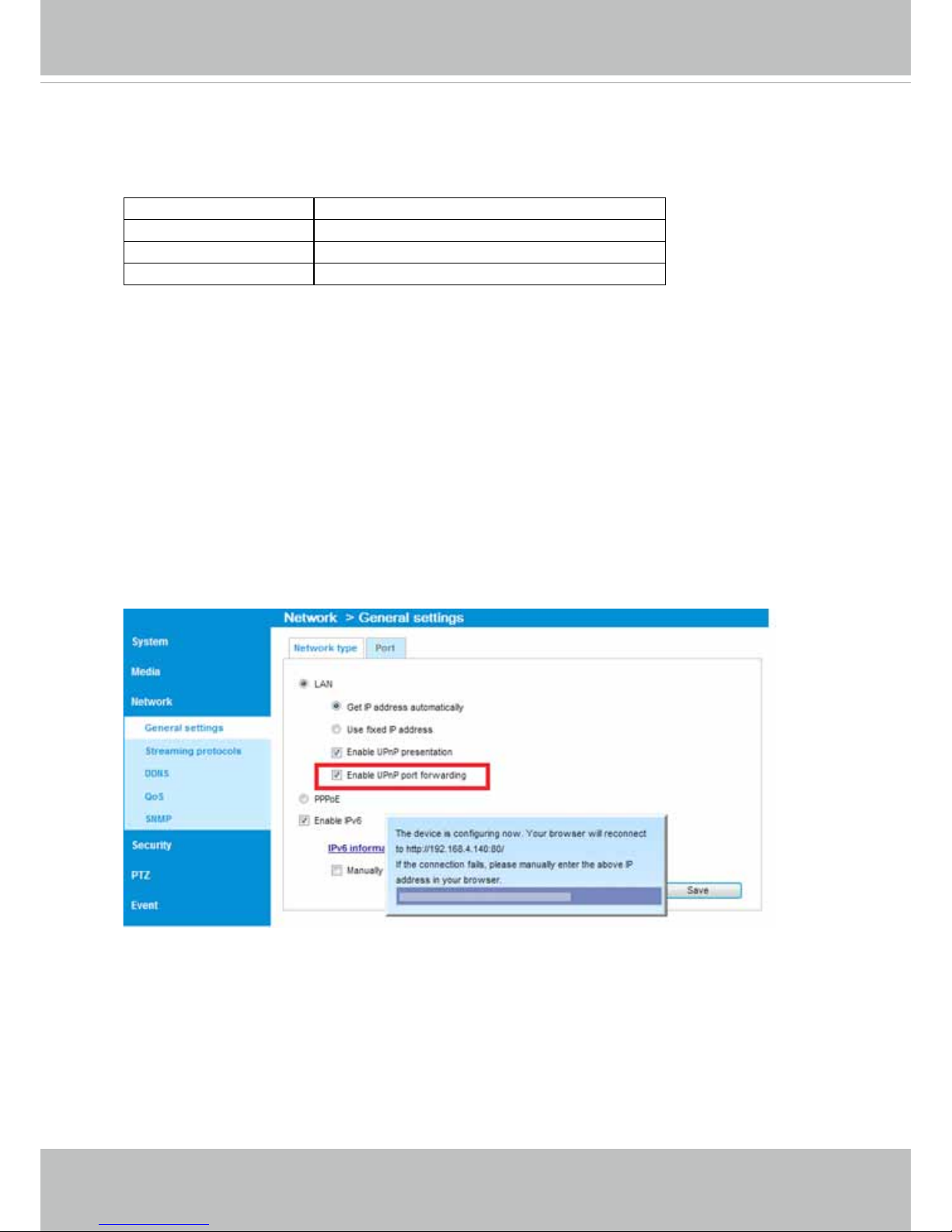
please refer to Conguration > Network Settings. VIVOTEK also provides the automatic
port forwarding feature as an NAT traversal function with the precondition that your router
must support the UPnP port forwarding feature.
Page 23
VIVOTEK
User's Manual - 19
Software Installation
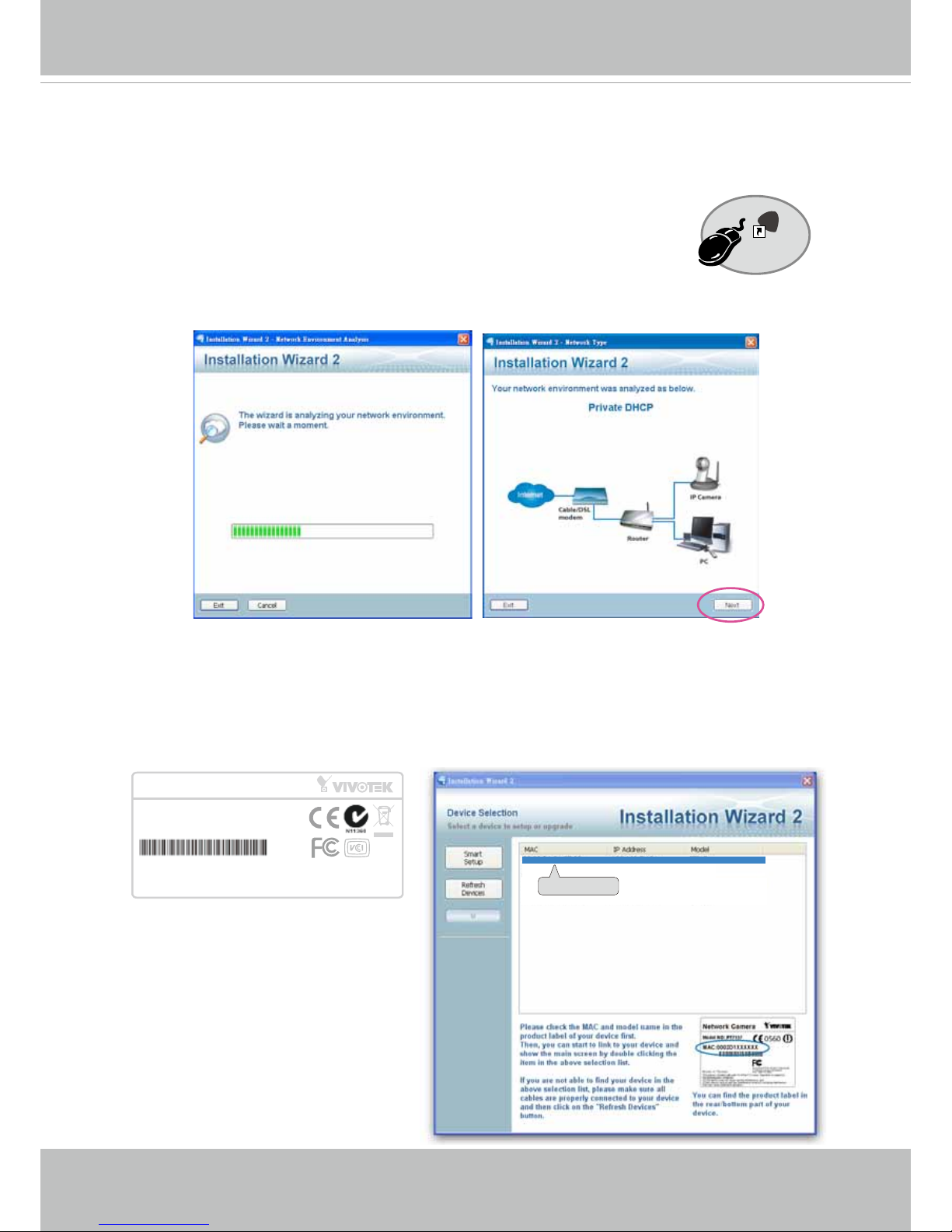
Installation Wizard 2 (IW2), a software included in the product CD, helps you set up your
Network Camera on the LAN.
1. Install IW2 under the Software Utility directory from the software CD.
Double-click the IW2 shortcut on your desktop to launch the program.
2. The program will conduct an analysis of your network environment.
After your network environment is analyzed, please click Next to continue the program.
3. The program will search for all VIVOTEK network devices on the same LAN.
4. After a brief search, the installer window will prompt. Click on the MAC and model name
that matches the one printed on the product label. You can then double-click on the address
to open a management session with the Network Camera.
0002D1730202
00-02-D1-73-02-02 192.168.5.151 IB836B
Installation
Wizard 2
IW
2
Network Camera
Model No: IB836B
Made in Taiwan
This device complies with part 15 of the FCC rules. Operation is subject to the following two conditions:
(1)This device may not cause harmful interference, and
(2) this device must accept any interference received, including interference that may cause undesired operation.
Pat. 6,930,709
MAC:0002D1730202
R o H S
Page 24
VIVOTEK
20 - User's Manual
Ready to Use
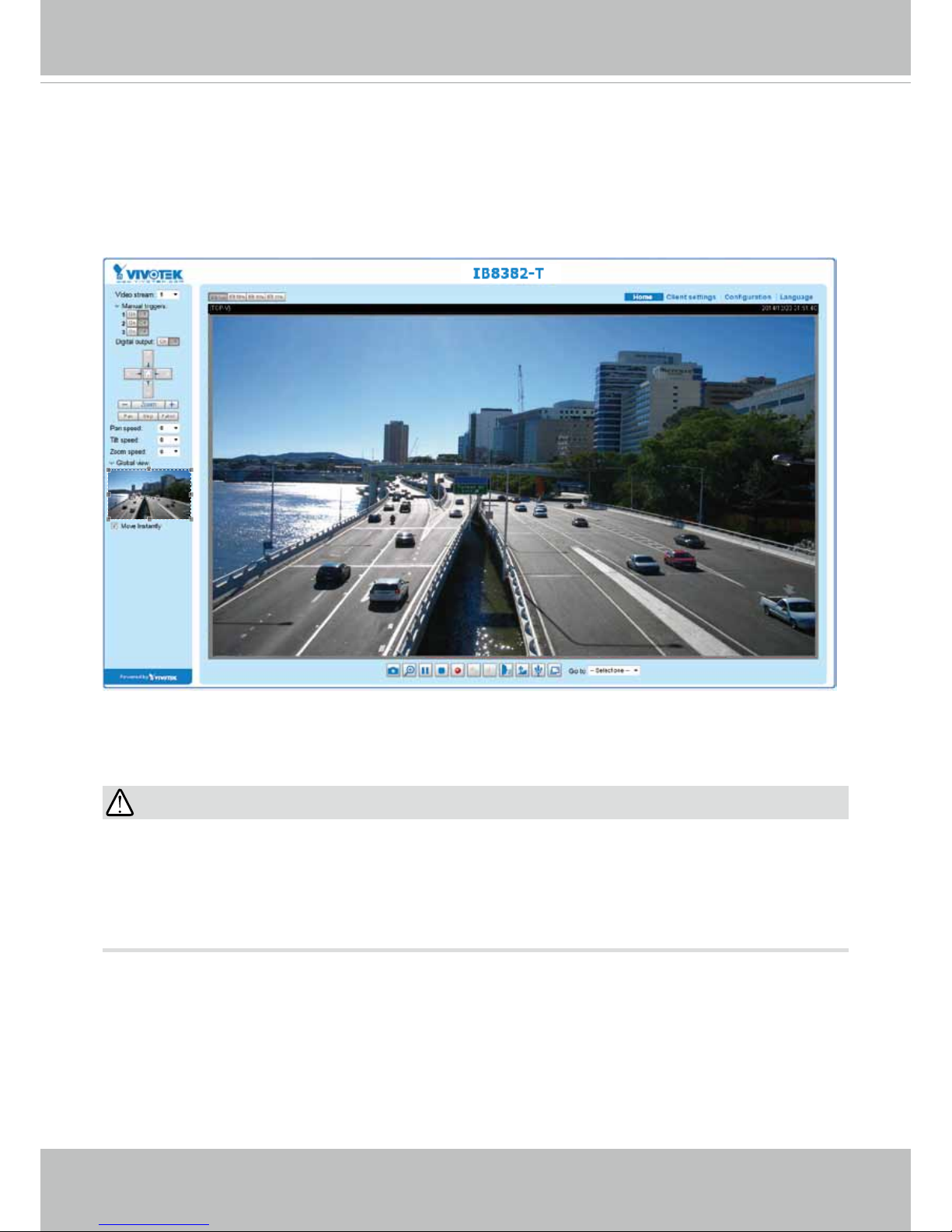
1. A browser session with the Network Camera should prompt as shown below.
2. You should be able to see live video from your camera. You may also install the 32-channel
recording software from the software CD in a deployment consisting of multiple cameras. For
its installation details, please refer to its related documents.
•
The "E" models, e.g., IB8382-ET, IB836B-EHT, are able to operate in low temperature
environments. However, when starting these cameras in a very low termperature condition,
e.g., -40ºC, the embedded heater may take half an hour to warm up the camera. When the
temperature within the canister reaches -10ºC, the camera automatically starts.
IMPORTANT:
Page 25
VIVOTEK
User's Manual - 21
Auto Focus
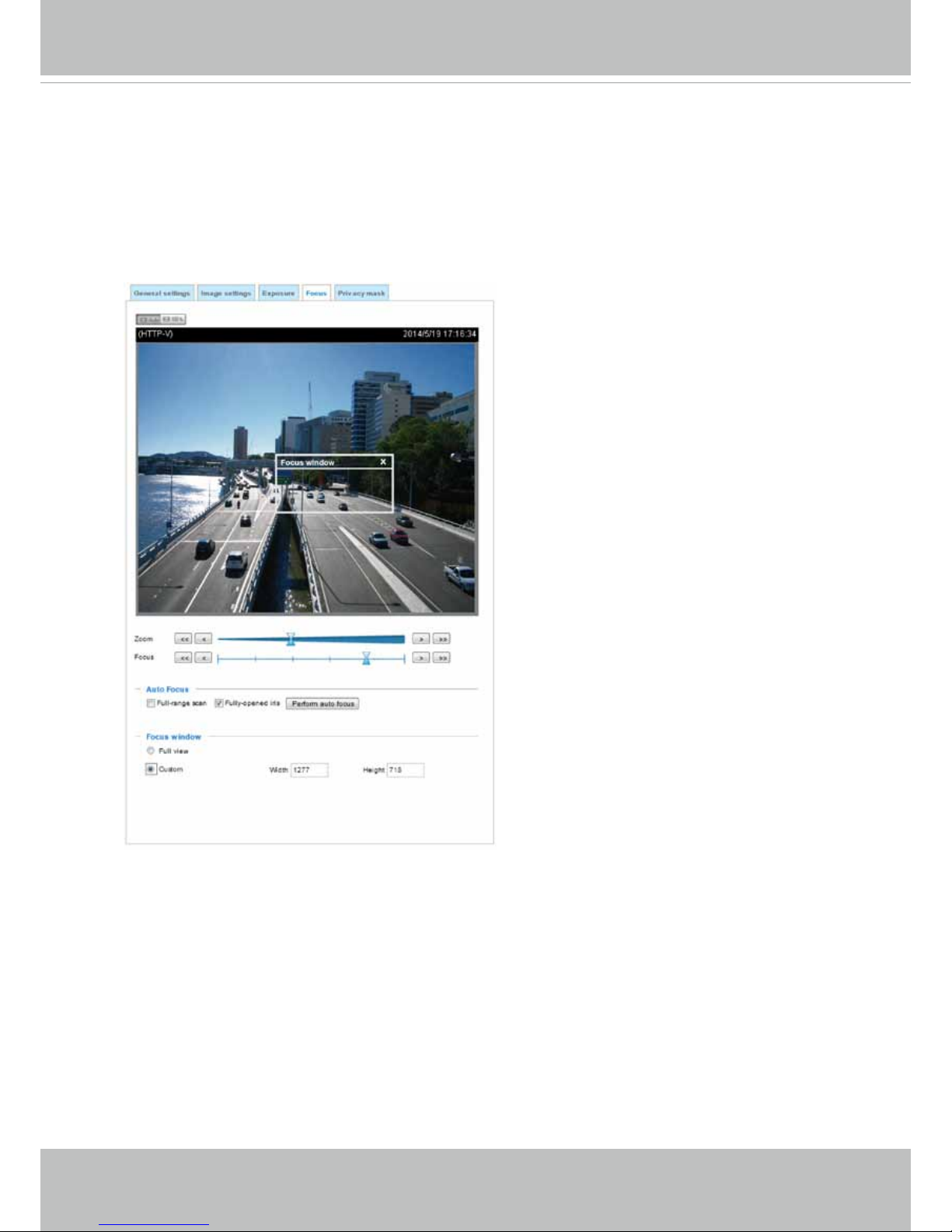
On the web session, visit the Configuration > Image > Focus window. Perform the
Auto Focus function for best image. However, if you have cascaded cameras, do this
one by one. Do not perform this function simultaneously on multiple cameras because
the motorized lens also consume considerable amount of power, and may cause the last
camera on the line to hang.
Page 26
VIVOTEK
22 - User's Manual
Accessing the Network Camera
This chapter explains how to access the Network Camera through web browsers, RTSP players,
3GPP-compatible mobile devices, and VIVOTEK recording software.
Using Web Browsers
Use Installation Wizard 2 (IW2) to access the Network Cameras on LAN.
If your network environment is not a LAN, follow these steps to access the Netwotk Camera:
1. Launch your web browser (e.g., Microsoft
®
Internet Explorer or Mozilla Firefox).
2. Enter the IP address of the Network Camera in the address eld. Press Enter.
3. Live video will be displayed in your web browser.
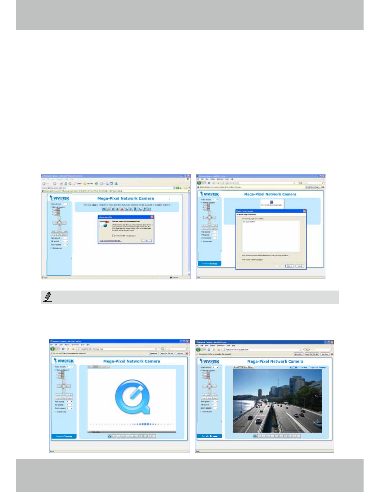
4. If it is the rst time installing the VIVOTEK network camera, an information bar will prompt as
shown below. Follow the instructions to install the required plug-in on your computer.
NOTE
► For Mozilla Firefox or Chrome users, your browser will use Quick Time to stream the live
video. If you don’t have Quick Time on your computer, please download it rst, then launch
the web browser.
NOTE:
Page 27

VIVOTEK
User's Manual - 23
► By default, the Network Camera is not password-protected. To prevent unauthorized access,
it is highly recommended to set a password for the Network Camera.
For more information about how to enable password protection, please refer to Security on
page 91.
► If you see a dialog box indicating that your security settings prohibit running ActiveX
®
Controls, please enable the ActiveX
®
Controls for your browser.
1. Choose Tools > Internet Options > Security > Custom Level.
2. Look for Download signed ActiveX
®
controls; select Enable or Prompt. Click OK.
3. Refresh your web browser, then install the ActiveX
®
control. Follow the instructions to
complete installation.
Page 28
VIVOTEK
24 - User's Manual
•
Currently the Network Camera utilizes a 32-bit ActiveX plugin. You CAN NOT open a
management/view session with the camera using a 64-bit IE browser.
•
If you encounter this problem, try execute the Iexplore.exe program from C:\Windows\
SysWOW64. A 32-bit version of IE browser will be installed.
•
On Windows 7, the 32-bit explorer browser can be accessed from here:
C:\Program Files (x86)\Internet Explorer\iexplore.exe
•
If you open a web session from the IW2 utility, a 32-bit IE browser will be opened.
IMPORTANT:
1. The onscreen Java control can malfunction under the following situations: A PC con-
nects to different cameras that are using the same IP address (or the same camera
running different rmware versions). Removing your browser cookies will solve this
problem.
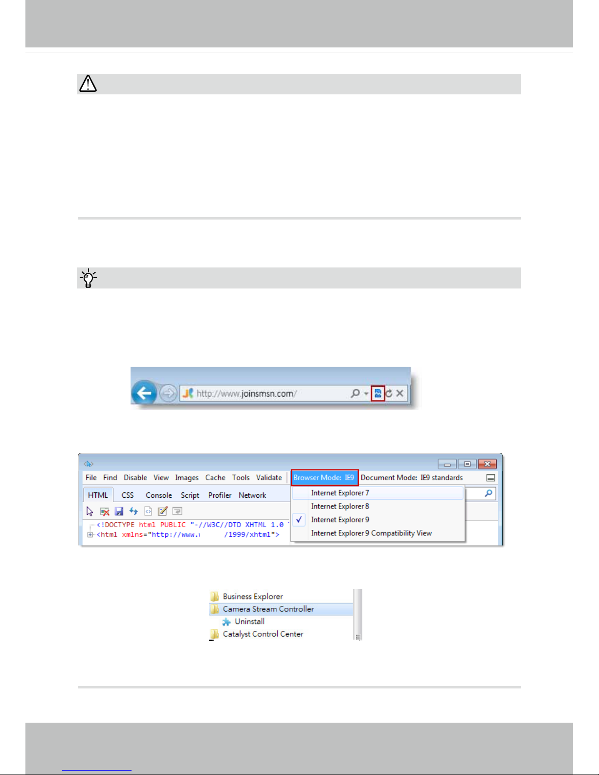
2. If you encounter problems with displaying the conguration menus or UI items, try dis-
able the Compatibility View on IE8 or IE9.
You may also press the F12 key to open the developer tools utility, and then change the
Browser Mode to the genuine IE8 or IE9 mode.
Tips:
• In the event of plug-in compatibility issues, you may try to uninstall the plug-in that was
previously installed.
Page 29
VIVOTEK
User's Manual - 25
Using RTSP Players
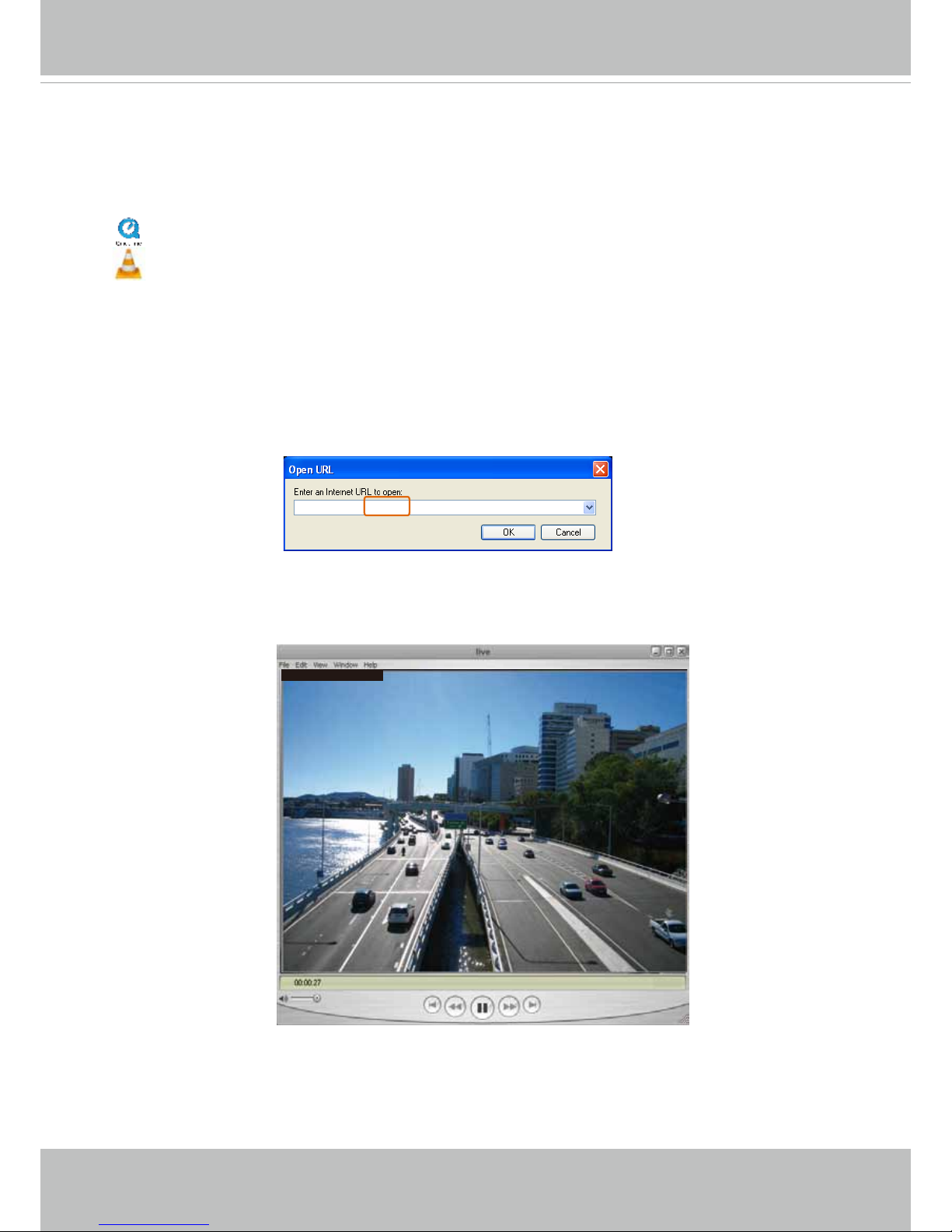
To view the streaming media using RTSP players, you can use one of the following players that
support RTSP streaming.
Quick Time Player
VLC media player
VLC media player
mpegable Player
pvPlayer
As most ISPs and players only allow RTSP streaming through port number 554, please set the
RTSP port to 554. For more information, please refer to RTSP Streaming on page 82.
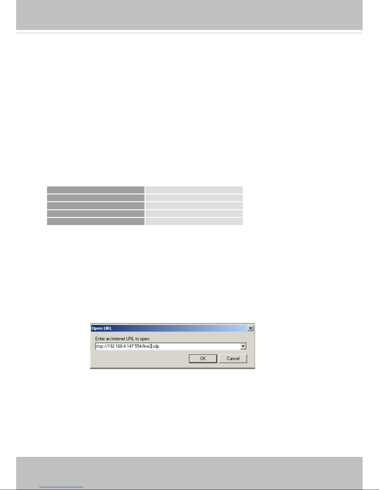
For example:
4. The live video will be displayed in your player.
For more information on how to configure the RTSP access name, please refer to RTSP
Streaming on page 82 for details.
rtsp://192.168.5.151:554/live.sdp
1. Launch the RTSP player.
2. Choose File > Open URL. A URL dialog box will pop up.
3. The address format is rtsp://<ip address>:<rtsp port>/<RTSP streaming access name for
stream1 or stream2>
Video 16:38:01 2012/01/25
Page 30
VIVOTEK
26 - User's Manual
Using 3GPP-compatible Mobile Devices
To view the streaming media through 3GPP-compatible mobile devices, make sure the Network
Camera can be accessed over the Internet. For more information on how to set up the Network
Camera over the Internet, please refer to Setup the Network Camera over the Internet on page
16.
To utilize this feature, please check the following settings on your Network Camera:
1. Because most players on 3GPP mobile phones do not support RTSP authentication, make
sure the authentication mode of RTSP streaming is set to disable.
For more information, please refer to RTSP Streaming on page 82.
2. As the the bandwidth on 3G networks is limited, you will not be able to use a large video size.
Please set the video streaming parameters as listed below.
For more information, please refer to Stream settings on page 64.
Video Mode H.264
Frame size 176 x 144
Maximum frame rate 5 fps
Intra frame period 1S
Video quality (Constant bit rate) 40kbps
3. As most ISPs and players only allow RTSP streaming through port number 554, please set
the RTSP port to 554. For more information, please refer to RTSP Streaming on page 82.
4. Launch the player on the 3GPP-compatible mobile devices (e.g., Quick Time).
5. Type the following URL commands into the player.
The address format is rtsp://<public ip address of your camera>:<rtsp port>/<RTSP streaming
access name for stream # with small frame size and frame rate>.
For example:
You can configure Stream #2 into the suggested stream settings as listed above for live
viewing on a mobile device.
Page 31
VIVOTEK
User's Manual - 27
Using VIVOTEK Recording Software
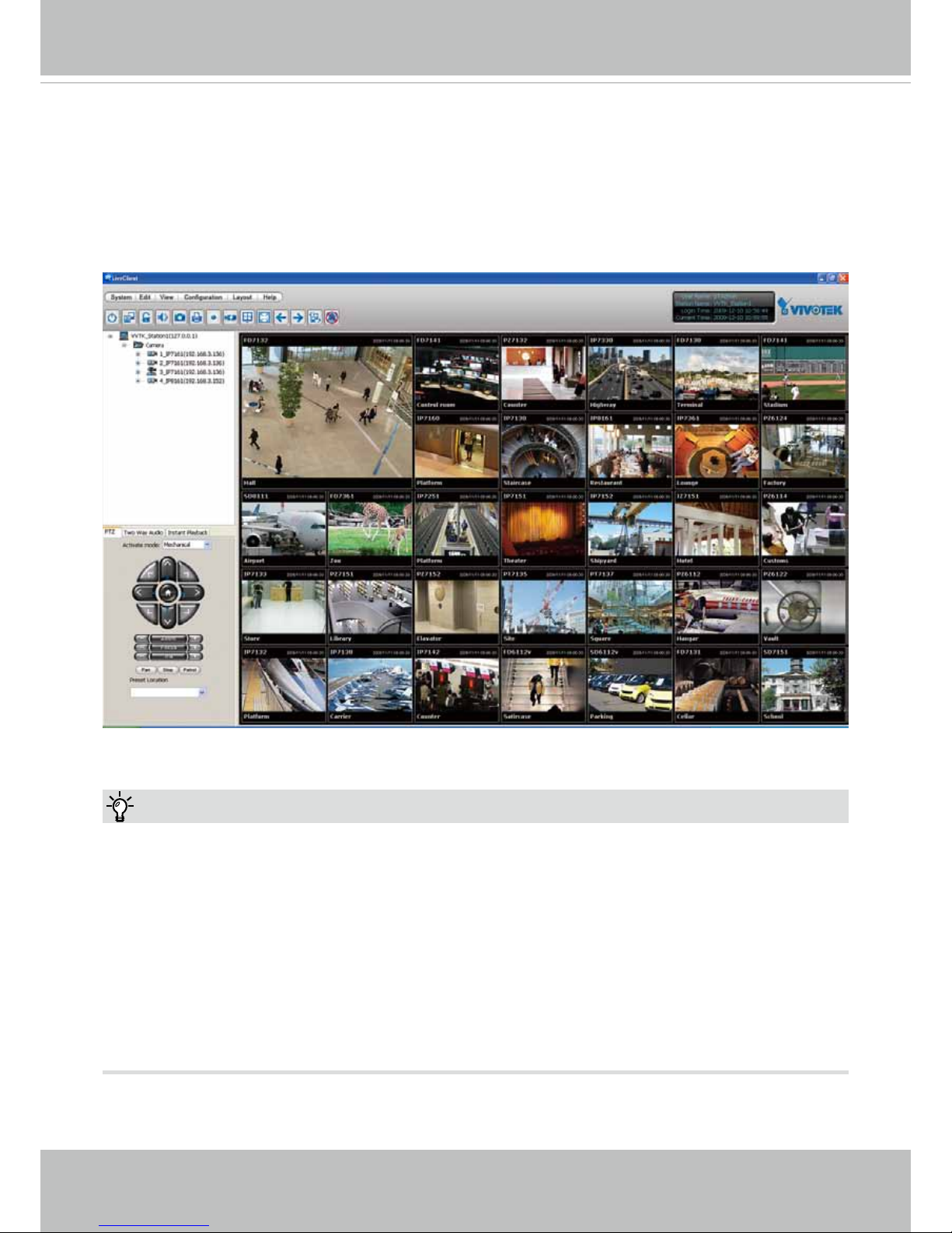
The product software CD also contains an ST7501 recording software, allowing simultaneous
monitoring and video recording for multiple Network Cameras. Please install the recording
software; then launch the program to add the Network Camera to the Channel list. For detailed
information about how to use the recording software, please refer to the user’s manual of the
software or download it from http://www.vivotek.com.
1. If you forget the root (administrator) password for the camera, you can restore the camera
defaults by pressing the reset button for longer than 5 seconds.
2. If DHCP is enabled in your network, and the camera cannot be accessed, run the IW2 utility
to search the network. If the camera has been congured with xed IP that does not comply
with your local network, you may see its default IP 169.254.x.x. If you still cannot find the
camera, you can restore the camera to its factory defaults.
3. If you change your network parameters, e.g., added a camera via a connection to a LAN
card, re-start the IW2 utility.
Tips:
Page 32
VIVOTEK
28 - User's Manual
Main Page
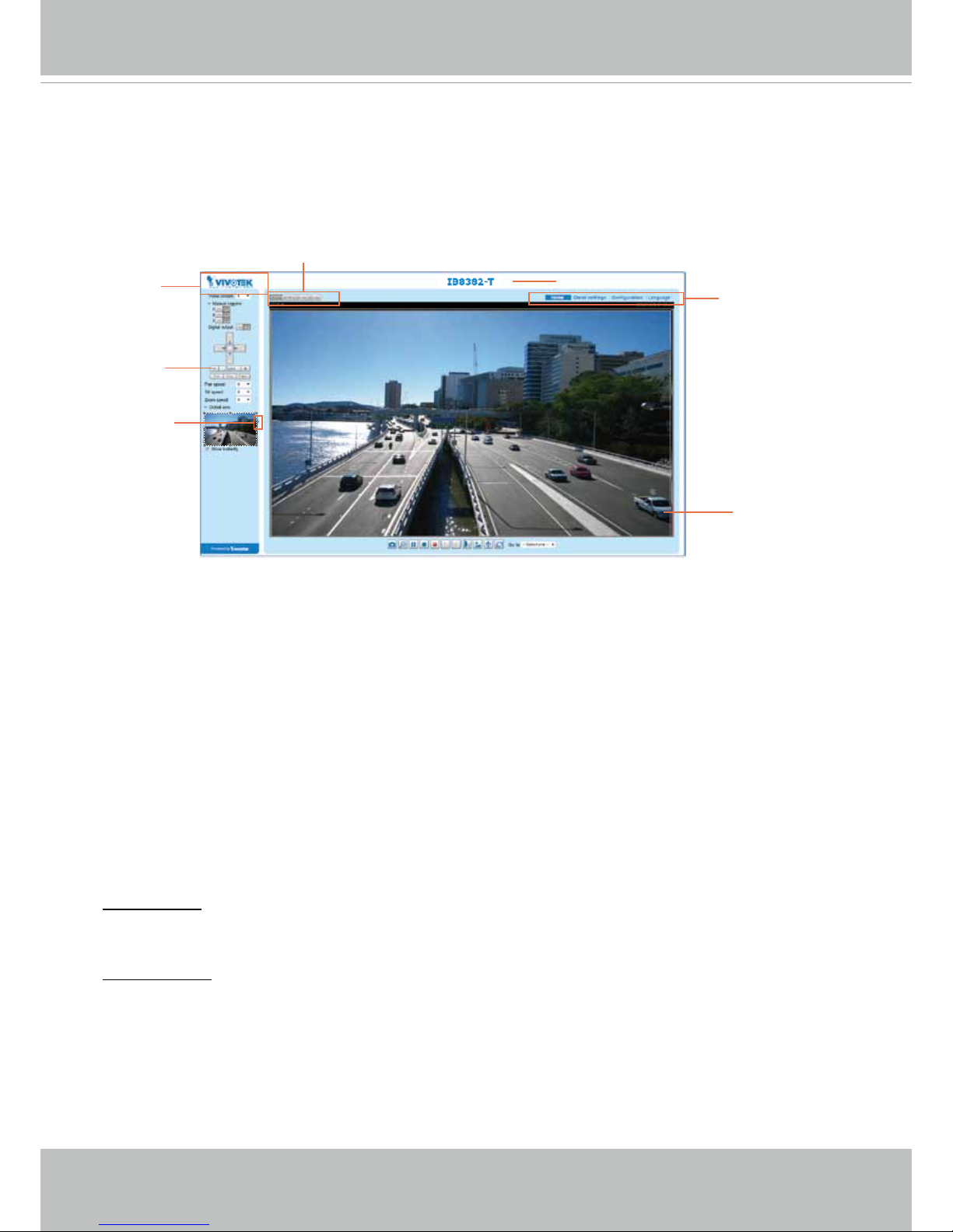
This chapter explains the layout of the main page. It is composed of the following sections:
VIVOTEK INC. Logo, Host Name, Camera Control Area, Configuration Area, Menu, and Live
Video Window.
VIVOTEK INC. Logo
Click this logo to visit the VIVOTEK website.
Host Name
The host name can be customized to t your needs. The name can be changed especially there are many
cameras in your surveillance deployment. For more information, please refer to System on page 39.
Camera Control Area
Video Stream: This Network Camera supports multiple streams (streams 1 and 2) simultaneously. You
can select any of them for live viewing. For more information about multiple streams, please refer to page
64 for detailed information.
Manual Trigger: Click to enable/disable an event trigger manually. Please congure an event setting on
the Application page before you enable this function. A total of 3 event conguration can be congured.
For more information about event setting, please refer to page 107. If you want to hide this item on
the homepage, please go to Configuration> System > Homepage Layout > General settings >
Customized button to deselect the “show manual trigger button” checkbox.
VIVOTEK INC.
Logo
Live View Window
Camera Control
Area
Configuration
Area
Host Name
Resize Buttons
Hide Button
Page 33

VIVOTEK
User's Manual - 29
Conguration Area
Client Settings: Click this button to access the client setting page. For more information, please refer to
Client Settings on page 33.
Conguration: Click this button to access the conguration page of the Network Camera. It is suggested
that a password be applied to the Network Camera so that only the administrator can configure the
Network Camera. For more information, please refer to Conguration on page 38.
Language: Click this button to choose a language for the user interface. Language options are available
in: English, Deutsch, Español, Français, Italiano,
日本語
, Português,
簡体中文
, and
繁體中文
. Please
note that you can also change a language on the Conguration page; please refer to page 38.
Hide Button
You can click the hide button to hide or display the control panel.
Resize Buttons
:
Click the Auto button, the video cell will resize automatically to t the monitor.
Click 100% is to display the original homepage size.
Click 50% is to resize the homepage to 50% of its original size.
Click 25% is to resize the homepage to 25% of its original size.
Live Video Window
■ The following window is displayed when the video mode is set to H.264:
Video Title: The video title can be congured. For more information, please refer to Video Settings on
page 51.
H.264 Protocol and Media Options: The transmission protocol and media options for H.264 video
streaming. For further conguration, please refer to Client Settings on page 33.
Time: Display the current time. For further conguration, please refer to Media > Image > Genral settings
on page 51.
Title and Time: The video title and time can be stamped on the streaming video. For further conguration,
please refer to Media > Image > General settings on page 56.
Video 17:08:56 2015/03/25
Title and Time
2015/03/25 17:08:56
Time
Video (TPC-AV)
H.264 Protocol and Media Options
Video Title
x4.0
Zoom Indicator
Video Control Buttons
Page 34

VIVOTEK
30 - User's Manual
Global View: Click on this item to display the Global View window. The Global View window contains a
full view image (the largest frame size of the captured video) and a oating frame (the viewing region of
the current video stream). The oating frame allows users to control the e-PTZ function (Electronic Pan/
Tilt/Zoom). For more information about e-PTZ operation, please refer to E-PTZ Operation on page 104.
For more information about how to set up the viewing region of the current video stream, please refer to
page 104.
The viewing region of
the curruent video
stream
The largest frame size
PTZ Panel: This Network Camera supports “digital“ (e-PTZ) pan/tilt/zoom control, which allows roaming
a smaller view frame within a large view frame. Please refer to PTZ settiings on page 104 for detailed
information.
Note that the PTZ buttons on the panel are not operational unless you are showing only a portion of the
full image. If the live view window is displaying the full view, the PTZ buttons are not functional.
Page 35

VIVOTEK
User's Manual - 31
Video Control Buttons: Depending on the Network Camera model and Network Camera conguration,
some buttons may not be available.
Snapshot: Click this button to capture and save still images. The captured images will be displayed
in a pop-up window. Right-click the image and choose Save Picture As to save it in JPEG (*.jpg) or BMP
(*.bmp) format.
Digital Zoom: Click and uncheck “Disable digital zoom” to enable the zoom operation. The navigation
screen indicates the part of the image being magnied. To control the zoom level, drag the slider bar. To
move to a different area you want to magnify, drag the navigation screen.
Pause: Pause the transmission of the streaming media. The button becomes the Resume button
after clicking the Pause button.
Stop: Stop the transmission of the streaming media. Click the Resume button to continue
transmission.
Start MP4 Recording: Click this button to record video clips in MP4 file format to your computer.
Press the
Stop MP4 Recording button to end recording. When you exit the web browser, video
recording stops accordingly. To specify the storage destination and le name, please refer to MP4 Saving
Options on page 34 for details.
Volume: When the Mute function is not activated, move the slider bar to adjust the volume on the
local computer.
Mute: Turn off the volume on the local computer. The button becomes the Audio On button after
clicking the Mute button.
Talk: Click this button to talk to people around the Network Camera. Audio will project from
the external speaker connected to the Network Camera. Click this button
again to end talking
transmission.
Mic Volume: When the Mute function is not activated, move the slider bar to adjust the
microphone volume on the local computer.
NOTE:
1. For a megapixel camera, it is recommended to use monitors of the 24" size or larger, and
are capable of 1600x1200 or better resolutions.
2. Below are the defaults for Audio settings:
For cameras with built-in microphone: Not Muted.
For cameras without built-in microphone: Muted.
To receive audio input from an external microphone, you may need to enable the audio input
from Media > Audio. Refer to page 72 for more information.
Page 36

VIVOTEK
32 - User's Manual
Mute: Turn off the Mic volume on the local computer. The button becomes the Mic On button
after clicking the Mute button.
Full Screen: Click this button to switch to full screen mode. Press the “Esc” key to switch back to normal
mode.
■ The following window is displayed when the video mode is set to MJPEG:
Video Title: The video title can be congured. For more information, please refer to Media > Image on
page 56.
Time: Display the current time. For more information, please refer to Media > Image on page 56.
Title and Time: Video title and time can be stamped on the streaming video. For more information, please
refer to Media > Image on page 56
.
Video Control Buttons: Depending on the Network Camera model and Network Camera conguration,
some buttons may not be available.
Snapshot: Click this button to capture and save still images. The captured images will be displayed
in a pop-up window. Right-click the image and choose Save Picture As to save it in JPEG (*.jpg) or BMP
(*.bmp) format.
Digital Zoom: Click and uncheck “Disable digital zoom” to enable the zoom operation. The navigation
screen indicates the part of the image being magnied. To control the zoom level, drag the slider bar. To
move to a different area you want to magnify, drag the navigation screen.
Start MP4 Recording: Click this button to record video clips in MP4 file format to your computer.
Press the
Stop MP4 Recording button to end recording. When you exit the web browser, video
recording stops accordingly. To specify the storage destination and le name, please refer to MP4 Saving
Options on page 34 for details.
Full Screen: Click this button to switch to full screen mode. Press the “Esc” key to switch back to normal
mode.
Video 17:08:56 2015/07/25
Title and Time
2015/07/25 17:08:56
Time
Video (HTTP-V)
Video Title
Video Control Buttons
Page 37
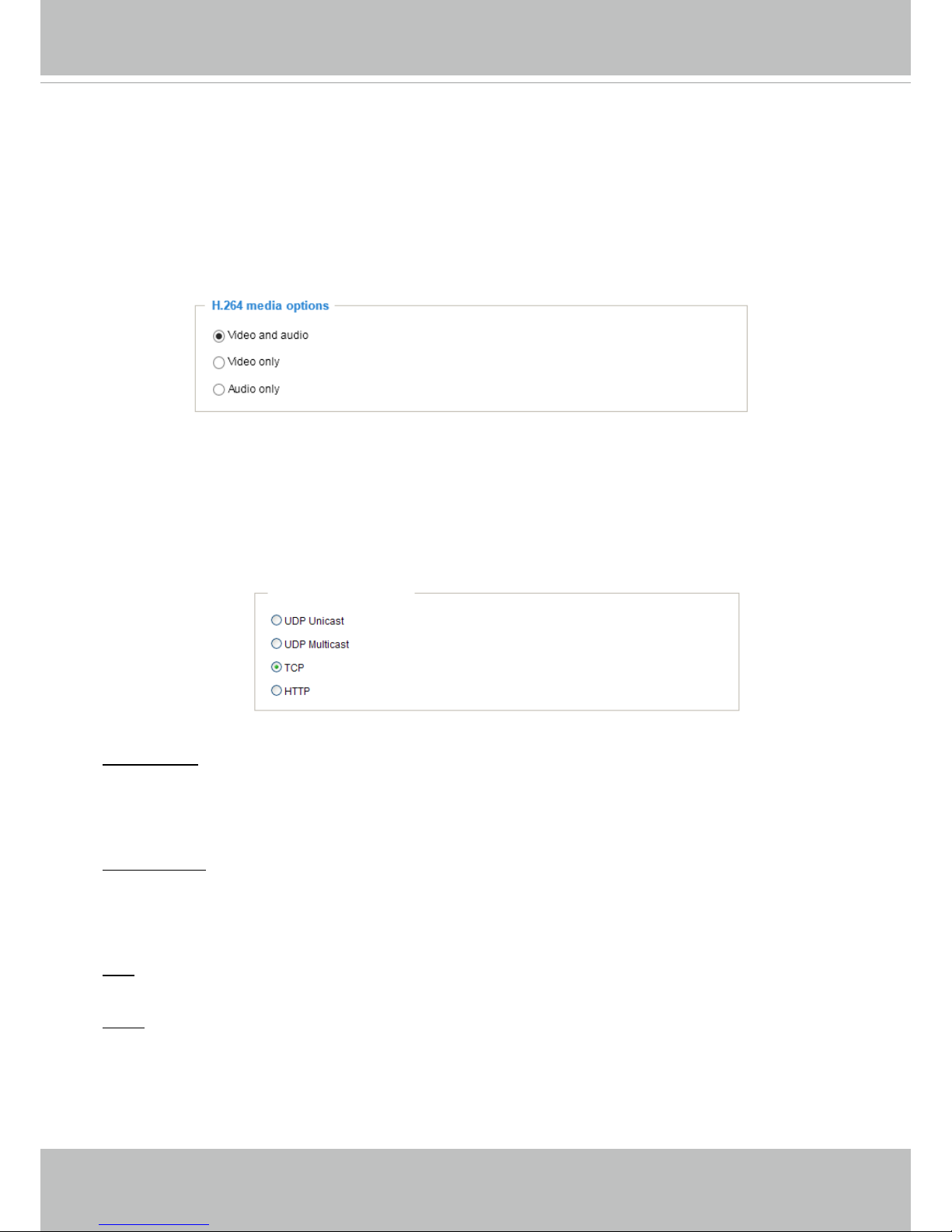
VIVOTEK
User's Manual - 33
Client Settings
This chapter explains how to select the stream transmission mode and saving options on the
local computer. When completed with the settings on this page, click Save on the page bottom
to enable the settings.
H.264 Protocol Options
H.264 Media Options
Select to stream video or audio data or both. This is enabled only when the video mode is set to H.264.
H.264 Protocol Options
Depending on your network environment, there are four transmission modes of H.264 streaming:
UDP unicast: This protocol allows for more real-time audio and video streams. However, network
packets may be lost due to network burst trafc and images may be broken. Activate UDP connection
when occasions require time-sensitive responses and the video quality is less important. Note that each
unicast client connecting to the server takes up additional bandwidth and the Network Camera allows up
to ten simultaneous accesses.
UDP multicast: This protocol allows multicast-enabled routers to forward network packets to all clients
requesting streaming media. This helps to reduce the network transmission load of the Network Camera
while serving multiple clients at the same time. Note that to utilize this feature, the Network Camera must
be configured to enable multicast streaming at the same time. For more information, please refer to
RTSP Streaming on page 82.
TCP: This protocol guarantees the complete delivery of streaming data and thus provides better video
quality. The downside of this protocol is that its real-time effect is not as good as that of the UDP protocol.
HTTP: This protocol allows the same quality as TCP protocol without needing to open specic ports for
streaming under some network environments. Users inside a firewall can utilize this protocol to allow
streaming data through.
Page 38

VIVOTEK
34 - User's Manual
MP4 Saving Options
Users can record live video as they are watching it by clicking Start MP4 Recording on the main
page. Here, you can specify the storage destination and le name.
Folder: Specify a storage destination on your PC for the recorded video files. The location can be
changed.
File name prex: Enter the text that will be appended to the front of the video le name. A specied folder
will be automatically created on your local hard disk.
Add date and time sufx to the le name: Select this option to append the date and time to the end of the
le name.
Local Streaming Buffer Time
In the case of encountering unsteady bandwidth, live streaming may lag and video streaming may not be
very smoothly. If you enable this option, the live streaming will be stored temporarily on your PC’s cache
memory for a few milli seconds before being played on the live viewing window. This will help you see
the streaming more smoothly. If you enter 3,000 Millisecond, the streaming will delay for 3 seconds.
CLIP_20150321-180853
Date and time suffix
The format is: YYYYMMDD_HHMMSS
File name prefix
Two way audio
Half duplex: Audio is transmitted from one direction at a time, e.g., from a PC holding a web console with
the camera.
Full duplex: Audio is transmitted in both directions simultaneously.
Page 39

VIVOTEK
User's Manual - 35
Joystick settings
Enable Joystick
Connect a joystick to a USB port on your management computer. Supported by the plug-in
(Microsoft’s DirectX), once the plug-in for the web console is loaded, it will automatically detect if
there is any joystick on the computer. The joystick should work properly without installing any other
driver or software.
Then you can begin to configure the joystick settings of connected devices. Please follow the
instructions below to enable joystick settings.
1. Select a detected joystick, if there are multiple, from the Selected joystick menu. If your joystick
is not detected, if may be defective.
2. Click Calibrate or Congure buttons to congure the joystick-related settings.
• If you want to assign Preset actions to your joystick, the preset locations should be congured in
advance in the Conguration > PTZ page.
• If your joystick is not working properly, it may need to be calibrated. Click the Calibrate button
to open the Game Controllers window located in Microsoft Windows control panel and follow the
instructions for trouble shooting.
NOTE:
• The joystick will appear in the Game Controllers list in the Windows Control panel. If you want to
check out for your devices, go to the following page: Start -> Control Panel -> Game Controllers.
Page 40
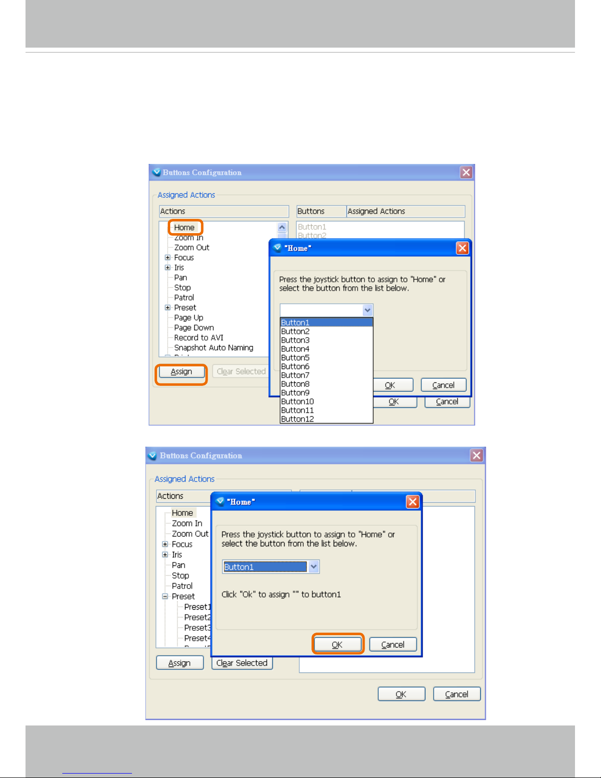
VIVOTEK
36 - User's Manual
Buttons Conguration
In the Button Conguration window, the left column shows the actions you can assign, and the right
column shows the functional buttons and assigned actions. The number of buttons may differ from
different joysticks.
Please follow the steps below to congure your joystick buttons:
1. Choosing one of the actions and click Assign will pop up a dialog. Then you can assign this
action to a button by pressing the joystick button or select it from the drop-down list.
For example: Assign Home (move to home position) to Button 1.
2. Click OK to conrm the conguration.
Page 41

VIVOTEK
User's Manual - 37
Buttons Conguration
Click the Congure Buttons button, a window will prompt as shown below. Please follow the steps
below to congure your joystick buttons:
1. Select a button number from the Button # pull-down menu.
2. Select a corresponding action, such as Patrol or Preset#.
If you are not sure of the locations of each
button, use the Properties window in the Game
Controllers utility.
Tips:
3.
Click the Assign button to assign an action
to the button. You can delete an association
by selecting a button number, and then click
the Delete button.
Repeat the process until you are done with
the conguration of all preferred actions.
The buttons you dene should appear on the
button list accordingly.
4. Please remember to c
lick the Save button
on the Client settings page to preserver your
settings.
Page 42

VIVOTEK
38 - User's Manual
Conguration
Click Configuration on the main page to enter the camera setting pages. Note that only
Administrators can access the conguration page.
VIVOTEK provides an easy-to-use user interface that helps you set up your network camera
with minimal effort. In order to simplify the user interface, detailed information will be hidden
unless you click on the function item. When you click on the first sub-item, the detailed
information for the rst sub-item will be displayed; when you click on the second sub-item, the
detailed information for the second sub-item will be displayed and that of the rst sub-item will
be hidden.
The following is the interface of the main page:
Configuration List
Firmware Version
Navigation Area
Each function on the conguration list will be explained in the following sections.
The Navigation Area provides access to all different views from the Home page (for live viewing),
Conguration page, and multi-language selection.
Page 43

VIVOTEK
User's Manual - 39
System > General settings
This section explains how to congure the basic settings for the Network Camera, such as the
host name and system time. It is composed of the following two columns: System, and System
Time. When finished with the settings on this page, click Save at the bottom of the page to
enable the settings.
System
Host name: Enter a desired name for the Network Camera. The text will be displayed at the top of the
main page, and also on the view cells of the ST7501 and VAST management software.
Turn off the LED indicators: If you do not want others to notice the network camera is in operation, you
can select this option to turn off the LED indicators.
Page 44
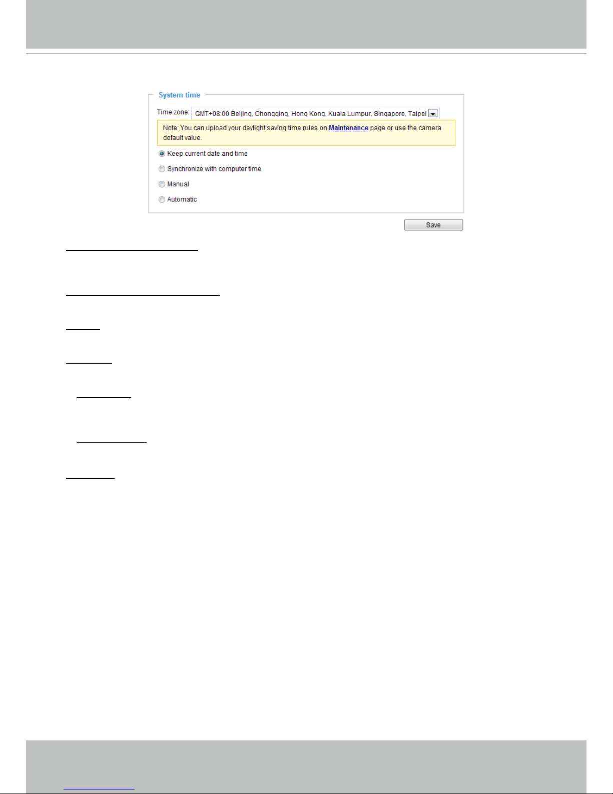
VIVOTEK
40 - User's Manual
System time
Keep current date and time: Select this option to preserve the current date and time of the Network
Camera. The Network Camera’s internal real-time clock maintains the date and time even when the
power of the system is turned off.
Synchronize with computer time: Select this option to synchronize the date and time of the Network
Camera with the local computer. The read-only date and time of the PC is displayed as updated.
Manual: The administrator can enter the date and time manually. Note that the date and time format are
[yyyy/mm/dd] and [hh:mm:ss].
Automatic: The Network Time Protocol is a protocol which synchronizes computer clocks by periodically
querying an NTP Server.
NTP server: Assign the IP address or domain name of the time-server. Leaving the text box blank
connects the Network Camera to the default time servers. The precondition is that the camera must
have the access to the Internet.
Update interval: Select to update the time using the NTP server on an hourly, daily, weekly, or monthly
basis.
Time zone : Select the appropriate time zone from the list. If you want to upload Daylight Savings Time
rules, please refer to System > Maintenance > Import/ Export les on page 48 for details.
Page 45

VIVOTEK
User's Manual - 41
System > Homepage layout
This section explains how to set up your own customized homepage layout.
General settings
This column shows the settings of your hompage layout. You can manually select the background and
font colors in Theme Options (the second tab on this page). The settings will be displayed automatically
in this Preview eld. The following shows the homepage using the default settings:
■ Hide Powered by VIVOTEK: If you check this item, it will be removed from the homepage.
Logo graph
Here you can change the logo that is placed at the top of your homepage.
Follow the steps below to upload a new logo:
1. Click Custom and the Browse eld will appear.
2. Select a logo from your les.
3. Click Upload to replace the existing logo with a new one.
4. Enter a website link if necessary.
5. Click Save to enable the settings.
Customized button
If you want to hide manual trigger buttons on the homepage, please uncheck this item. This item is
checked by default.
Page 46
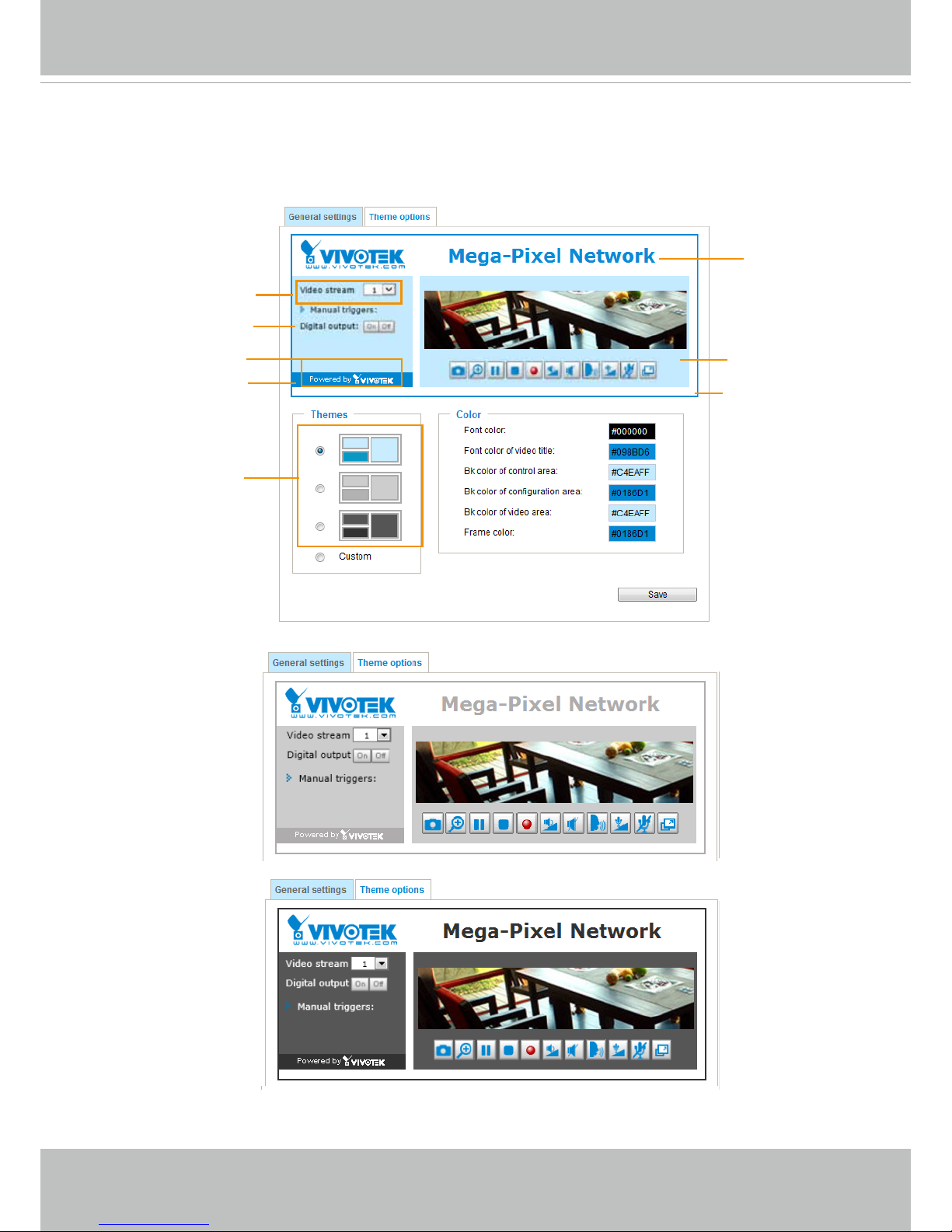
VIVOTEK
42 - User's Manual
Theme Options
Here you can change the color of your homepage layout. There are three types of preset patterns for you
to choose from. The new layout will simultaneously appear in the Preview led. Click Save to enable the
settings.
Font Color of the
Video Title
Background Color of
the Video Area
Frame Color
Font Color
Background Color of the
Control Area
Font Color of
the Configuration Area
Background Color of the
Configuration Area
Preset patterns
Page 47

VIVOTEK
User's Manual - 43
■ Follow the steps below to set up the customed homepage:
1. Click Custom on the left column.
2. Click the eld where you want to change the color on the right column.
3. The palette window will pop up as shown below.
4. Drag the slider bar and click on the left square to select a desired color.
5. The selected color will be displayed in the corresponding elds and in the Preview column.
6. Click Save to enable the settings.
1
2
3
4
Color Selector
Custom
Pattern
Page 48

VIVOTEK
44 - User's Manual
System > Logs
This section explains how to congure the Network Camera to send the system log to a remote
server as backup.
Log server settings
Follow the steps below to set up the remote log:
1. Select Enable remote log.
2. In the IP address text box, enter the IP address of the remote server.
2. In the port text box, enter the port number of the remote server.
3. When completed, click Save to enable the setting.
You can congure the Network Camera to send the system log le to a remote server as a log backup.
Before utilizing this feature, it is suggested that the user install a log-recording tool to receive system log
messages from the Network Camera. An example is Kiwi Syslog Daemon. Visit http://www.kiwisyslog.
com/kiwi-syslog-daemon-overview/.
System log
This column displays the system log in a chronological order. The system log is stored in the Network
Camera’s buffer area and will be overwritten when reaching a certain limit.
Page 49
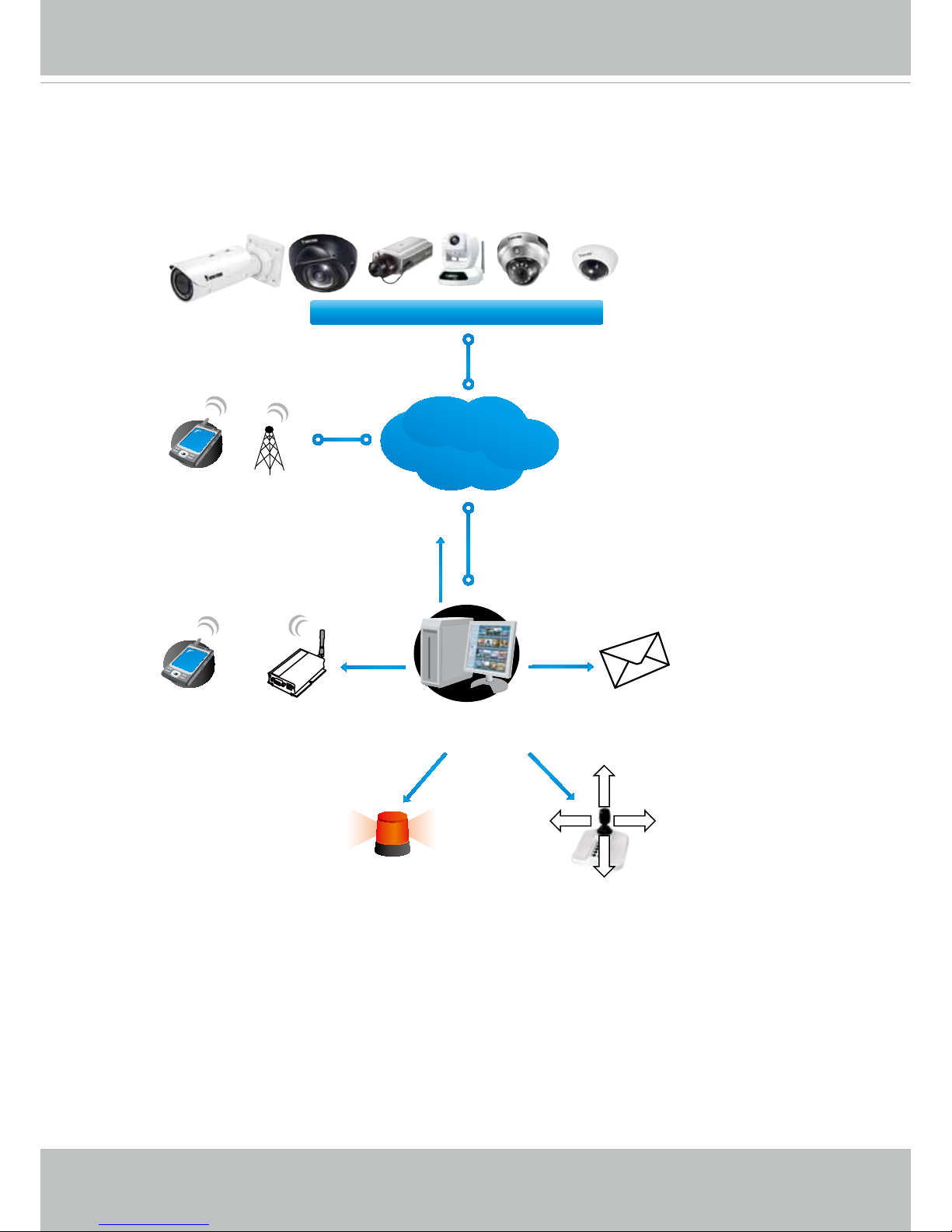
VIVOTEK
User's Manual - 45
PC running
ST7501 Recording Software
Internet
VIVOTEK Network Cameras
3G Cell phone
Cell phone
Short message
Email
GSM
Modem
HTTP
PTZ
Digital output
You can install the included ST7501 recording software, which provides an Event
Management function group for delivering event messages via emails, GSM short
messages, onscreen event panel, or to trigger an alarm, etc. For more information, refer to
the ST7501 User Manual.
Page 50
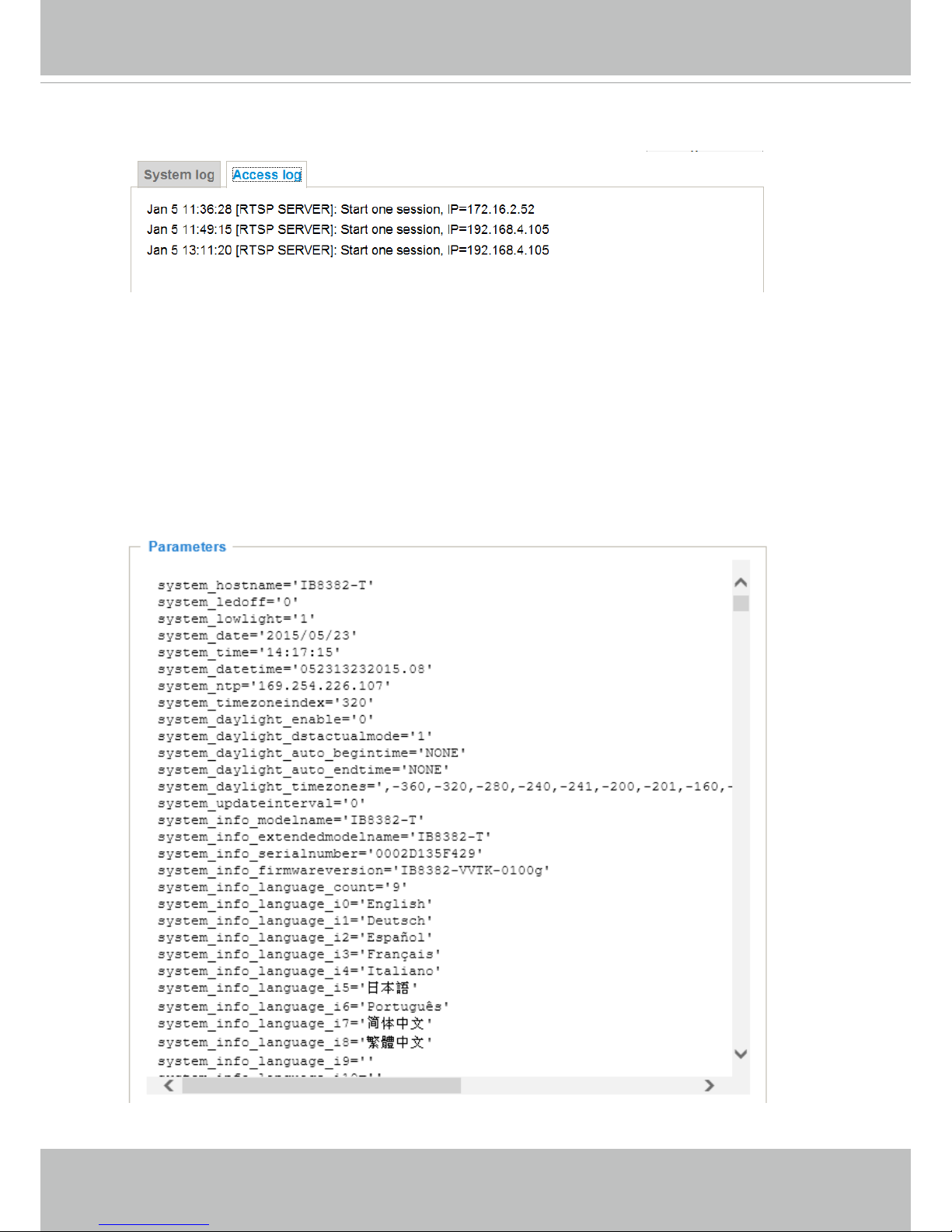
VIVOTEK
46 - User's Manual
Access log
Access log displays the access time and IP address of all viewers (including operators and
administrators) in a chronological order. The access log is stored in the Network Camera’s buffer
area and will be overwritten when reaching a certain limit.
System > Parameters
The View Parameters page lists the entire system’s parameters. If you need technical
assistance, please provide the information listed on this page.
Page 51
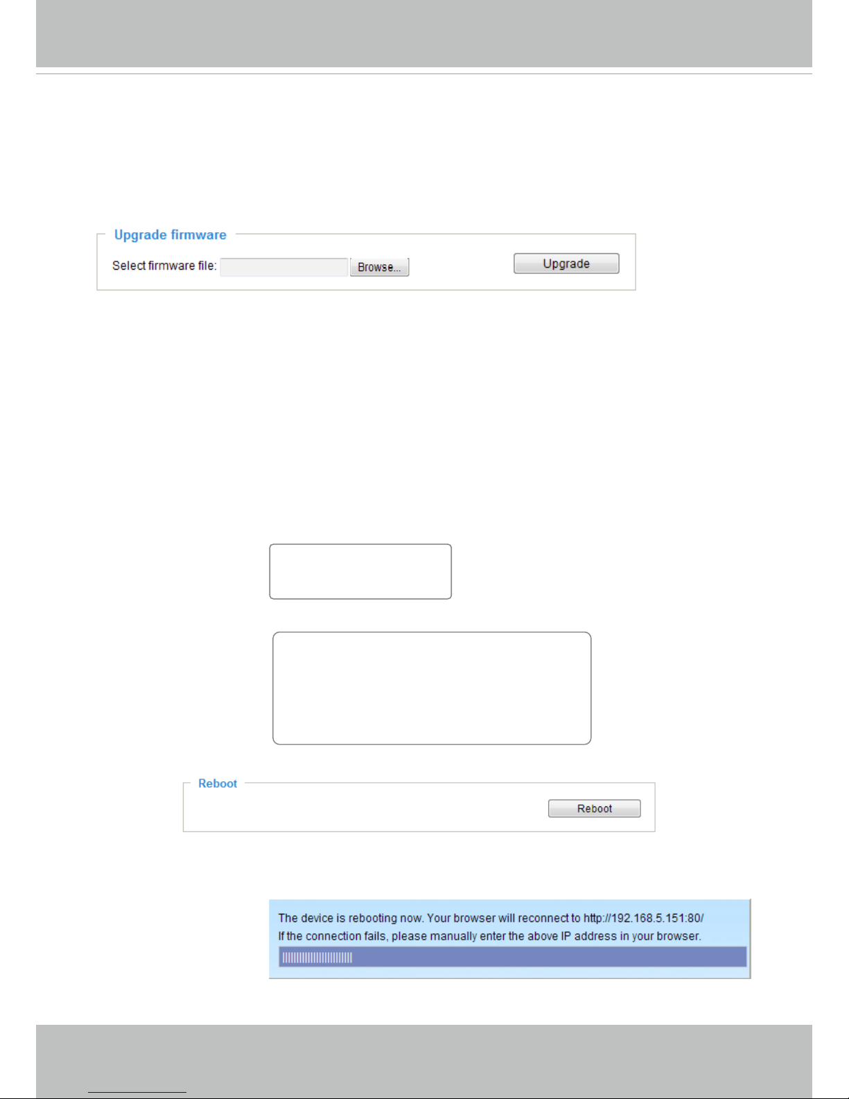
VIVOTEK
User's Manual - 47
System > Maintenance
This chapter explains how to restore the Network Camera to factory default, upgrade rmware
version, etc.
General settings > Upgrade rmware
This feature allows you to upgrade the firmware of your Network Camera. It takes a few minutes to
complete the process.
Note: Do not power off the Network Camera during the upgrade!
Follow the steps below to upgrade the rmware:
1. Download the latest rmware le from the VIVOTEK website. The le is in .pkg le format.
2. Click Browse… and locate the rmware le.
3. Click Upgrade. The Network Camera starts to upgrade and will reboot automatically when the upgrade
completes.
If the upgrade is successful, you will see “Reboot system now!! This connection will close”. After that, reaccess the Network Camera.
The following message is displayed when the upgrade has succeeded.
The following message is displayed when you have selected an incorrect rmware le.
General settings > Reboot
This feature allows you to reboot the Network Camera, which takes about one minute to complete. When
completed, the live video page will be displayed in your browser. The following message will be displayed
during the reboot process.
If the connection fails after rebooting, manually enter the IP address of the Network Camera in the
address eld to resume the connection.
Starting firmware upgrade...
Do not power down the server during the upgrade.
The server will restart automatically after the upgrade is
completed.
This will take about 1 - 5 minutes.
Wrong PKG file format
Unpack fail
Reboot system now!!
This connection will close.
Page 52
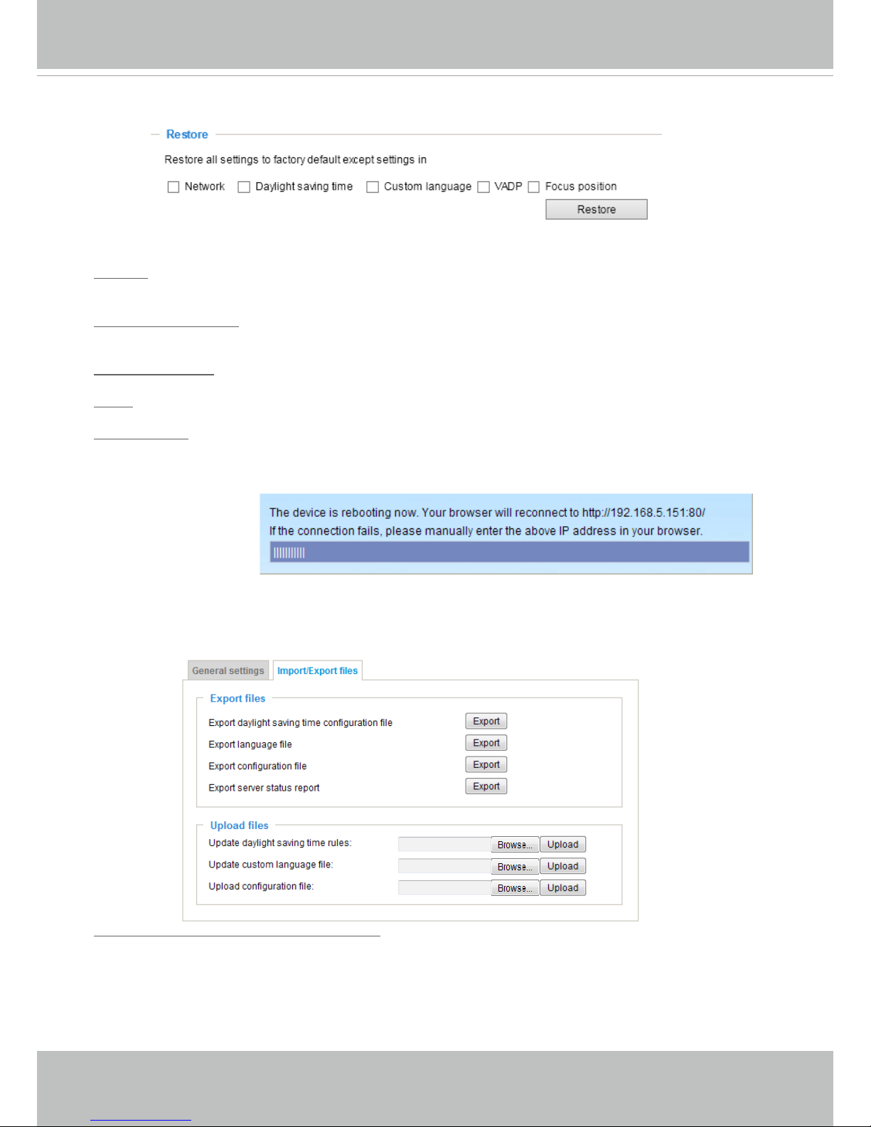
VIVOTEK
48 - User's Manual
General settings > Restore
This feature allows you to restore the Network Camera to factory default settings.
Network: Select this option to retain the Network Type settings (please refer to Network Type on page
74).
Daylight Saving Time: Select this option to retain the Daylight Saving Time settings (please refer to
Import/Export les below on this page).
Custom Language: Select this option to retain the Custom Language settings.
VADP: Retain the VADP modules (3rd-party software stored on the SD card) and related settings.
Focus position: Retain the lens focus position using the previously saved position parameters.
If none of the options is selected, all settings will be restored to factory default. The following message is
displayed during the restoring process.
Import/Export les
This feature allows you to Export / Update daylight saving time rules, custom language le, conguration
le, and server status report.
Export daylight saving time conguration le: Click to set the start and end time of DST (Daylight Saving).
Follow the steps below to export:
1. In the Export les column, click Export to export the daylight saving time conguration le from the
Network Camera.
2. A le download dialog will pop up as shown below. Click Open to review the XML le or click Save to
store the le for editing.
Page 53

VIVOTEK
User's Manual - 49
3. Open the le with Microsoft® Notepad and locate your time zone; set the start and end time of DST.
When completed, save the le.
In the example below, DST begins each year at 2:00 a.m. on the second Sunday in March and ends at
2:00 a.m. on the rst Sunday in November.
Update daylight saving time rules: Click Browse… and specify the XML le to update.
If the incorrect date and time are assigned, you will see the following warning message when uploading
the le to the Network Camera.
Page 54

VIVOTEK
50 - User's Manual
The following message is displayed when attempting to upload an incorrect le format.
Export language file: Click to export language strings. VIVOTEK provides nine languages: English,
Deutsch, Español, Français, Italiano,
日本語,
Português,
簡体中文
, and
繁體中文
.
Update custom language le: Click Browse… and specify your own custom language le to upload.
Export conguration le: Click to export all parameters for the device and user-dened scripts.
Update conguration le: Click Browse… to update a conguration le. Please note that the model and
rmware version of the device should be the same as the conguration le. If you have set up a xed IP
or other special settings for your device, it is not suggested to update a conguration le.
Export server staus report: Click to export the current server status report, such as time, logs,
parameters, process status, memory status, le system status, network status, kernel message ... and so
on.
Tips:
• If a firmware upgrade is accidentally disrupted, say, by a power outage, you still have a last resort
method to restore normal operation. See the following for how to bring the camera back to work:
Applicable scenario:
(a) Power disconnected during rmware upgrade.
(b) Unknown reason causing abnormal LED status, and a Restore cannot recover normal working
condition.
You can use the following methods to activate the camera with its backup rmware:
(a) Press and hold down the reset button for at least one minute.
(b) Power on the camera until the Red LED blinks rapidly.
(c) After boot up, the rmware should return to the previous version before the camera hanged. (The
procedure should take 5 to 10 minutes, longer than the normal boot-up process). When tthis
process is completed, the LED status should return to normal.
Page 55

VIVOTEK
User's Manual - 51
Media > Image
This section explains how to configure the image settings of the Network Camera. It is
composed of the following four columns: General settings, Picture settings, Exposure, and
Privacy mask. The Focus window is available only for models that come with motorized
lens.
General settings
Video title
Show_timestamp_and video_title_in_video_and_snapshots: Enter a name that will be displayed on
the title bar of the live video as the picture shown below. A zoom indicator will be displayed on the
Home page when you zoom in/out on the live viewing window as shown below. You may zoom in/
out on the image by scrolling the mouse wheel inside the live viewing window, and the maximum
zoom in will be up to 4 times.
Position of timestamp and video title on image: Select to display time stamp and video title on the
top or at the bottom of the video stream.
Timestamp and video title font size: Select the font size for the time stamp and title.
Video font (.ttf): You can select a True Type font le for the display of textual messages on video.
Color: Select to display color or black/white video streams.
Power line frequency: Set the power line frequency consistent with local utility settings to eliminate
image flickering associated with fluorescent lights. Note that after the power line frequency is
changed, you must disconnect and reconnect the power cord of the Network Camera in order for
the new setting to take effect.
Video Title
Title and Time
Video 17:08:56 2014/7/09
2014/7/09 17:08:56
X2.1
Zoom Factor
Zoom In
Zoom Out
Page 56

VIVOTEK
52 - User's Manual
Day/Night Settings
Switch to B/W in night mode
Select this to enable the Network Camera to automatically switch to Black/White during night
mode.
Turn on external IR illuminator in night mode
Select this to turn on the external IR illuminator when the camera detects low light condition and
enters the night mode. A Digital Output connection to external IR is needed.
Turn on built-in IR illuminator in night mode
Select this to turn on the camera’s onboard IR illuminator when the camera detects low light
condition and enters the night mode.
Rotate -
MirrorNormal Flip Rotate 90°
clockwise
The camera may be installed on a vertical, side-facing, or tilted surface in order to accommodate
the interior or exterior design of a building. The interior of a building can be shaped as a narrow
rectangular space, such as a corridor. The conventional HD image, such as that of a 16:9 aspect
ratio, will be incongruous with its wide horizontal view. With video rotation, the camera can more
readily cover the eld of view on a tall and narrow scene.
The rotation here indicates clockwise
rotation. Rotation can be applied with
flip, mirror, and physical lens rotation
(see below) settings to adapt to different
mounting locations.
The gures in the illustration are shown in
a consecutive order.
Video orientation: Flip - vertically reect the display of the live video; Mirror - horizontally reect the
display of the live video. Select both options if the Network Camera is installed upside-down (e.g.,
on the ceiling) to correct the image orientation. Please note that if you have preset locations, those
locations will be cleared after ip/mirror setting.
Page 57
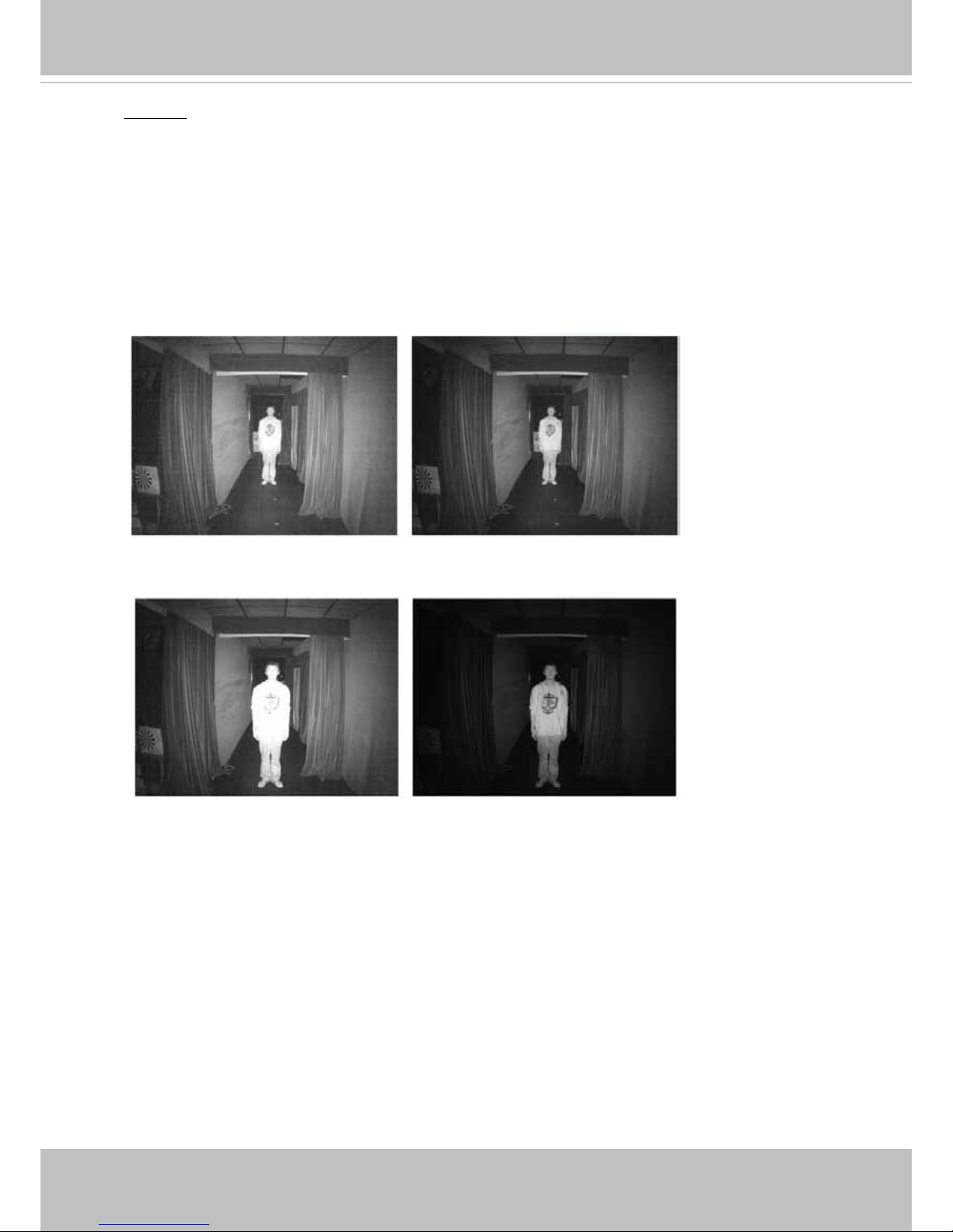
VIVOTEK
User's Manual - 53
Smart IR disabled; distance: 5M
Smart IR enabled; distance: 5M
Smart IR disabled; distance: 3M
Smart IR enabled; distance: 3M
The Smart IR function is more benecial when the spot of intrusions or an object of your interest
is close to the lens and the IR lights. For example, if an intruder has a chance of getting near the
range of 3 meters, Smart IR can effectively reduce the over-exposure. For a surveillance area at
a greater distance, e.g., 5 meters, the Smart IR function may not bring as signicant benets as in
close range.
Smart IR
When enabled, the camera automatically adjusts the IR projection to adjacent objects in order to
avoid over-exposure in the night mode.
Page 58

VIVOTEK
54 - User's Manual
IR cut lter
With a removable IR-cut lter, this Network Camera can automatically remove the lter to let IR
light enter the light sensor during low light conditions.
■ Auto mode
The Network Camera automatically removes the lter by judging the level of ambient light.
■ Day mode
In day mode, the Network Camera switches on the IR cut lter at all times to block infrared light
from reaching the sensor so that the colors will not be distorted.
■ Night mode
In night mode, the Network Camera switches off the IR cut lter at all times for the sensor to
accept infrared light, thus helping to improve low light sensitivity.
■ Synchronize with digital input
The Network Camera automatically removes the IR cut lter when a Digital Input is triggerred.
For example, the digital input can come from a housing that is equipped with IR illumination and
control circuits such as VIVOTEK’s AM-214.
Exclude x
Tips:
If there is an object in close proximity, the IR lights
reflected back from it can mislead the Smart IR’s
calculation of light level. To solve this problem, you
can place an “Exposure Exclude” window on an
unavoidable object in the Exposure setting window.
See page 59 for how to do it.
You can also configure the “Exposure Exclude”
window in a night mode “Prole” setting so that your
day time setting is not affected.
Exclude x
Page 59

VIVOTEK
User's Manual - 55
■ Schedule mode
The Network Camera switches between day mode and night mode based on a specified
schedule. Enter the start and end time for the day mode. Note that the time format is [hh:mm]
and is expressed in 24-hour clock time. By default, the start and end time of day mode are set to
07:00 and 18:00.
Light sensor sensitivity
Tune the responsiveness of the IR lter to lighting conditions as Low, Normal, or High.
When completed with the settings on this page, click Save to enable the settings.
Page 60

VIVOTEK
56 - User's Manual
Image settings
On this page, you can tune the White balance and Image adjustment.
White balance: Adjust the value for the best color temperature.
■ You may follow the steps below to adjust the white balance to the best color temperature.
1. Place a sheet of paper of white or cooler-color temperature color, such as blue, in front of the
lens, then allow the Network Camera to automatically adjust the color temperature.
2. Click the On button to Fix current value and conrm the setting while the white balance is being
measured.
■ You may also manually tune the color temperature by pulling the RGain and BGain slide bars.
Image Adjustment
■ Brightness: Adjust the image brightness level, which ranges from
0% to 100%
.
■ Contrast: Adjust the image contrast level, which ranges from 0% to 100%.
■ Saturation: Adjust the image saturation level, which ranges from 0% to 100%.
■ Sharpness:
Adjust the image sharpness level, which ranges from
0% to 100%
.
■ Gamma curve:
Adjust the image sharpness level, which ranges from
0 to 0.45
.
You may let firmware Optimize your display or select a value to change the preferred level of
Gamma correction towards higher contrast or towards the higher luminance for detailed expression
for both dark and lighted areas of an image.
Defog: Defog helps improve the visibility quality of captured image in poor weather conditions such
as smog, fog, or smoke.
Sensor Setting 2:
For special situations
Sensor Setting 1:
For normal situations
Page 61
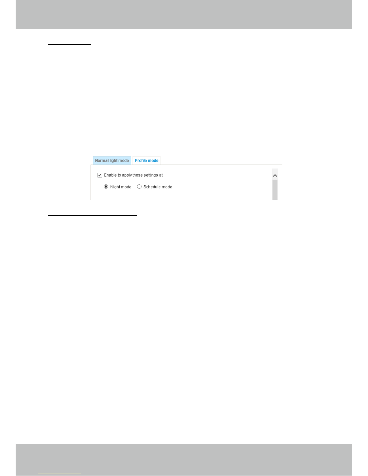
VIVOTEK
User's Manual - 57
Note that the Preview button has been cancelled, all changes made to image settings is directly
shown on screen. You can click Restore to recall the original settings without incorporating the
changes. When completed with the settings on this page, click Save to enable the setting. You
can also click on Prole mode to adjust all settings above in a tabbed window for special lighting
conditions.
Enable to apply these settings at:
Select the mode this prole to apply to: Day mode, Night mode, or
Schedule mode. Please manually enter a range of time if you choose Schedule mode. Then check
Save to take effect.
Noise reduction
■ Enable noise reduction: Check to enable noise reduction in order to reduce noises and ickers
in image. This applies to the onboard 3D Noise Reduction feature. Use the pull-down menu to
adjust the reduction strength. Note that applying this function to the video channel will consume
system computing power.
3D Noise Reduction is mostly applied in low-light conditions. When enabled in a low-light
condition with fast moving objects, trails of after-images may occur. You may then select a lower
strength level or disable the function.
Page 62

VIVOTEK
58 - User's Manual
Exposure
On this page, you can set the Exposure measurement window, Exposure level, Exposure mode,
Exposure time, Gain control, and Day/Night mode settings. You can congure two sets of Exposure
settings: one for normal situations, the other for special situations, such as the day/night/schedule
mode.
Measurement Window: This function allows users to set measurement window(s) for low light
compensation. For example, where low-light objects are posed against an extremely bright
background. You may want to exclude the bright sunlight shining through a building's corridor.
■ Full view: Calculate the full range of view and offer appropriate
light compensation.
■ Custom: This option allows you to manually add customized windows as inclusive or exclusive
regions. A total of 10 windows can be configured. Please refer to the next page for detailed
illustration.
Sensor Setting 1:
For normal situations
Sensor Setting 2:
For special situations
Page 63

VIVOTEK
User's Manual - 59
Exposure control:
■
Exposure level: You can manually set the Exposure level, which ranges from -2.0 to +2.0 (dark
to bright). You can click and drag the semi-circular pointers on the Exposure time and Gain
control slide bars to specify a range of shutter time and Gain control values within which the
camera can automatically tune to an optimal imaging result. You may prefer a shorter shutter
time to better capture moving objects, while a faster shutter reduces light and needs to be
compensated by electrical brightness gains.
■
Exposure mode:
You can click and drag the semi-circular pointers on the Exposure time and Gain control slide
bars to specify a range of shutter time and Gain control values within which the camera can
automaticallly tune to an optimal imaging result. You can also configure the iris size to control
the amount of light. For example, you may prefer a shorter shutter time to better capture moving
objects, while a faster shutter reduces light and needs to be compensated by electrical brightness
gains.
The inclusive window refers to the “weighed window“; the exclusive window refers to “ignored
window“. It adopts the weighed averages method to calculate the value. The inclusive windows
have a higher priority. You can overlap these windows, and, if you place an exclusive window
within a larger inclusive window, the exclusive part of the overlapped windows will be deducted
from the inclusive window. An exposure value will then be calculated out of the remaining of the
inclusive window.
■ BLC (Back Light Compensation): This option will automatically add a “weighted region“ in the
middle of the window and give the necessary light compensation.
Include
Exclude
Weighted region
Ignored region
Include
Exclude
Auto: If you set Exposure mode as Auto, the Exposure time and Gain control will not be
congurable since the sensor library will automatically adjust the value according to the ambient
light. Then you can congure iris mode as “indoor” or “outdoor” to reach the best image quality.
■ Iris mode:
Select Indoor or Outdoor iris mode to adapt to the installation. The preset iris aperture
setting will apply.
Page 64
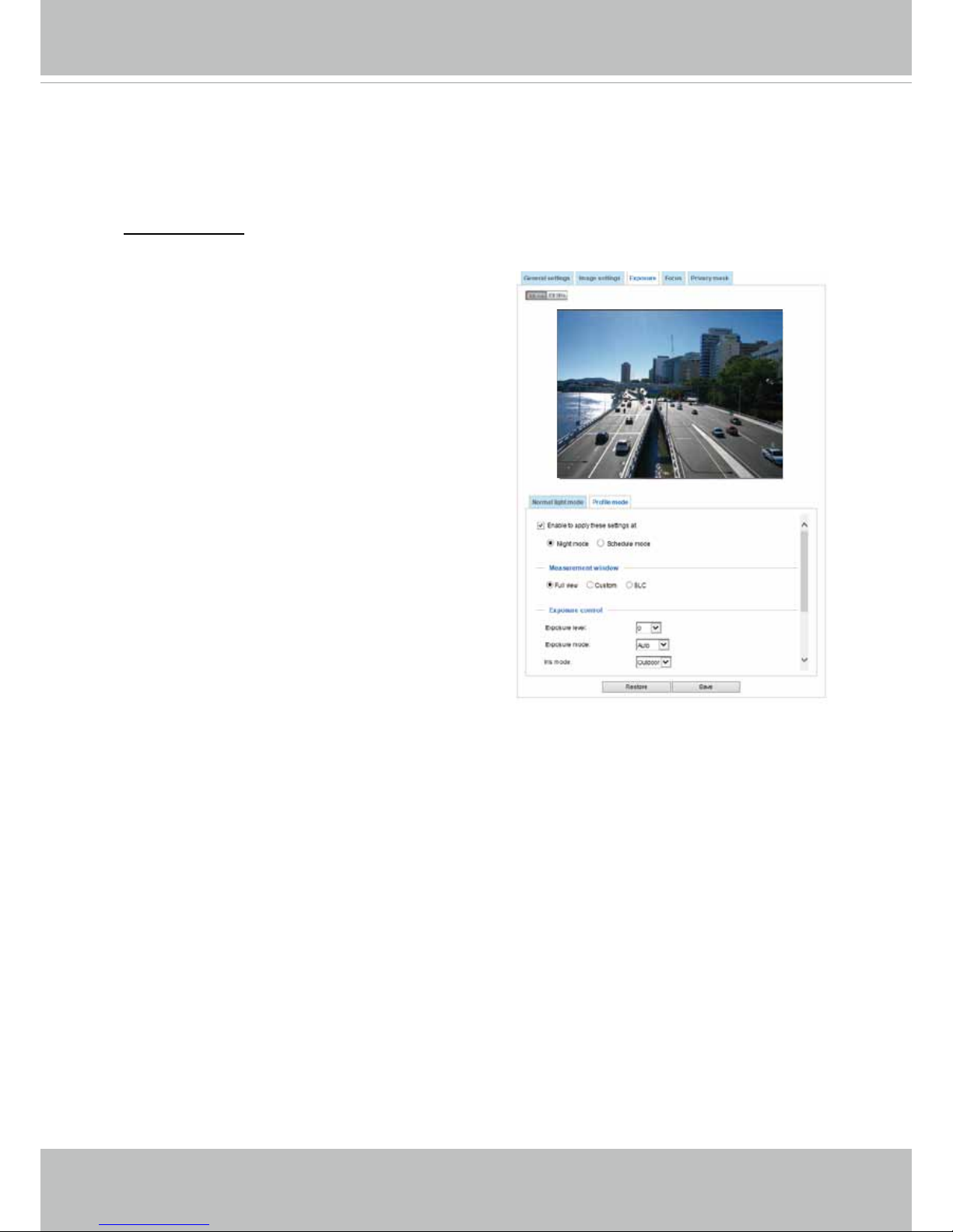
VIVOTEK
60 - User's Manual
Please follow the steps below to set up a prole:
1. Select the Prole mode tab.
2. Select the applicable mode: Night mode or
Schedule mode. Please manually enter a range of
time if you choose Schedule mode.
3. Congure Exposure control settings in the folowing
columns. Please refer to previous dicussions for
detailed information.
4. Click Save to enable the setting and click Close to
exit the page.
You can click Restore to recall the original settings without incorporating the changes. When
completed with the settings on this page, click Save to enable the settings.
If you want to congure another sensor setting for day/night/schedule mode, please click Prole to
open the Prole of exposure settings page as shown below.
Activated period:
Select the mode this profile to apply to: Day mode, Night mode, or Schedule
mode. Please manually enter a range of time if you choose Schedule mode. Then check Save to
take effect.
Page 65

VIVOTEK
User's Manual - 61
Focus (IB8382-ET, IB8382-RT IB836B-HT/EHT, IB836B-HRT)
Focus here refers to the Remote Focus, applicable to Network Cameras that are equipped
with a stepping motor lens. The automated focus adjustment function eliminates the needs
to physically adjust camera focus. In an outdoor deployment consisting of a large number
of cameras, the auto focus function can be very helpful when these cameras become out
of focus after days or weeks of operation. And that can easily result from the effects of
natural forces, e.g., shrink and expand due to a wide range of operating temperatures and
the vibration caused by wind.
Below is the procedure to perform the automated Focus function:
1. Select from the bottom of the screen whether you want to perform focus adjustment on
the Full view or within a Custom focus window. You can create a custom window and
click and drag the window to a desired position on screen.
2. It is recommended to Reset to the default back focus position of the sensor board.
3. You can use the Open iris checkbox (default) to increase the iris size for a better focus
adjustment result.
4. Click to select the Fully-opened iris or the Full-range scan buttons. When a full-range
scan is selected, a full-range scan through the camera's entire focal length can take
about 30 to 80 seconds. If not, the auto focus scan will only go through the length where
optimal focus may occur, and that takes about 15 to 20 seconds. In theory, best results
of the auto scan can be acquired when the camera's iris is fully open.
Focus window
x
Page 66

VIVOTEK
62 - User's Manual
The methodology of using the Resize Buttons at the upper left corner of the streaming
window is the same as that on the home page.
Focus window:
By default, the optimal focus is found on a full view window. You may designate a custom window
within your current eld of view to acquire the best focus out of it. However, you can not place a
focus window on a distant background, e.g., a hall way that stretches away for 3 meters or farther.
Doing so you will not benet from the Focus window function.
■
Full view: The focus tuning takes place by referring to the full view.
■
Custom: You can create a focus window and drag it to a place of interest in your view window.
Note that it is recommended to use this function only when you have a solid object in your view
window that is showing a consistent color or texture. This function will not take effect if you set
the focus window on a distant background.
5. Wait for the scan to complete. After a short while, the clearest image obtained should be
displayed and the optimal focus range achieved. Use the arrow marks on the sides to
ne-tune the focus if you are not satised with the results.
You may still need to use the ar-
row marks to ne-tune the focus depending on the live image on your screen. “>” means moving
from wide to tele end; and “<” tele to wide.
You can try the Snapshot focus function (in Applications > Package management)
when applied in the above mentioned scenario.
Page 67
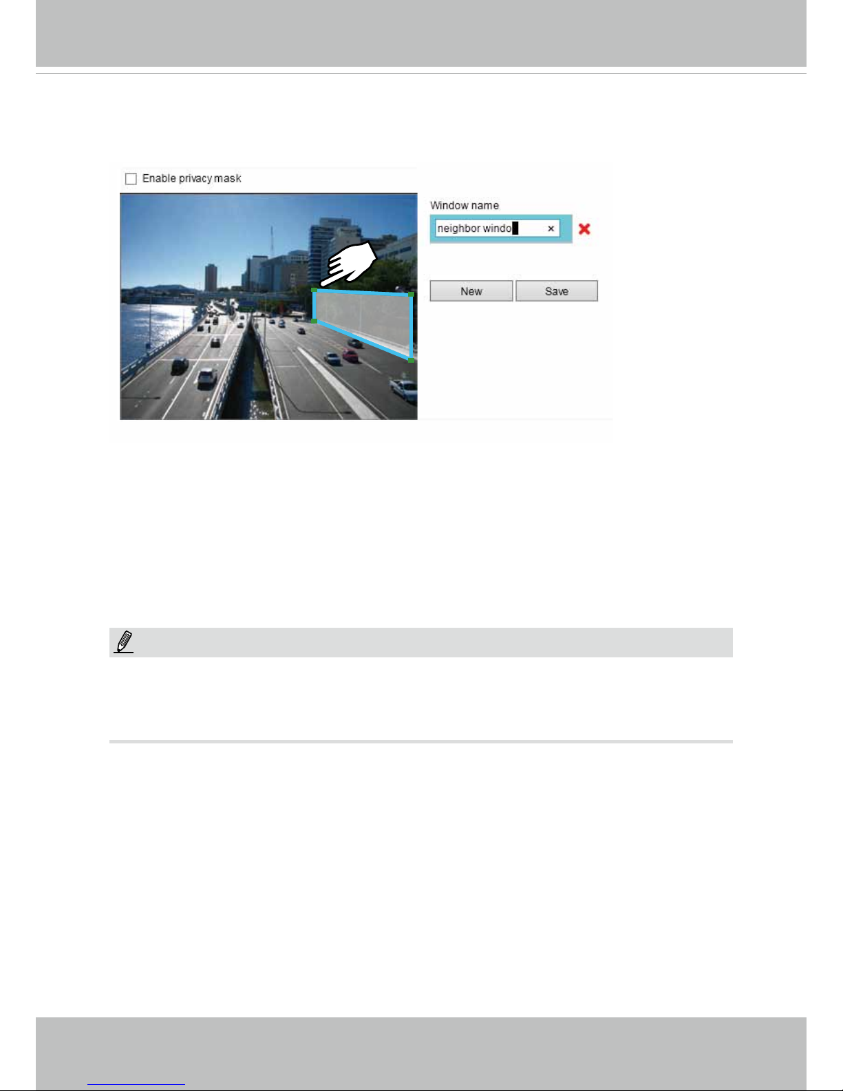
VIVOTEK
User's Manual - 63
Privacy mask
Click Privacy Mask to open the settings page. On this page, you can block out sensitive zones to
address privacy concerns.
■ To set the privacy mask windows, follow the steps below:
1. Click New to add a new window.
2. You can use 4 mouse clicks to create a new masking window, which is recommended to be at
least twice the size of the object (height and width) you want to cover.
3. Enter a Window Name and click Save to enable the setting.
4. Click on the Enable privacy mask checkbox to enable this function.
NOTE:
►
Up to 5 privacy mask windows can be set up on the same screen.
► If you want to delete the
privacy mask
window, please click the ‘x’ mark on the side of window
name.
Page 68
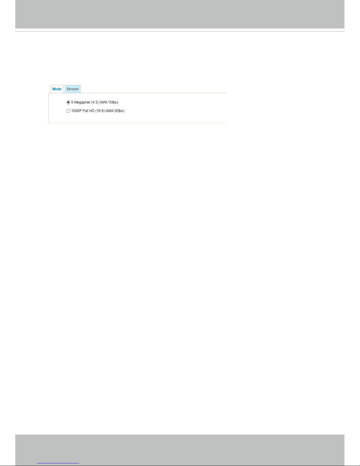
VIVOTEK
64 - User's Manual
Media > Video
Mode
You might select different resolutions, 5 megapixel at 15fps and 1080P Full HD at 30fps, with
different aspect ratios, 4:3 or 16:9 for the video streams. Note that changing the FOV will erase
your preset points, Motion detection, exposure window, and privacy masks settings.
Page 69

VIVOTEK
User's Manual - 65
Stream settings
This Network Camera supports multiple streams with frame sizes ranging from 176 x 144 to 2560 x
1920 pixels.
The denition of multiple streams:
■ Stream 1: Users can dene the "Region of Interest" (viewing region) and the "Output Frame Size"
(size of the live view window).
■ Stream 2: The default frame size for Stream 2 is set to the 1600 x 1200.
■ Stream 3: The default frame size for Stream 3 is set to the 640 x 480.
■ Stream 4: The default frame size for Stream 3 is set to the 2560 x 1920, and the Viewing Window
function is not available for stream 4.
Click Viewing Window to open the viewing region settings page. On this page, you can congure
the Region of Interest and the Output Frame Size for a video stream. For example, you can crop
only a portion of the image that is of your interest, and thus save the bandwidth needed to transmit
the video stream. As the picture shown below, the area of your interest in a parking lot should be
the vehicles. The blue sky is of little value for the surveillance purpose.
Page 70

VIVOTEK
66 - User's Manual
Media > Video
► All the items in the “Region of Interest” should not be larger than the “Output Frame Size“
(current maximum resolution).
■ The parameters of the multiple streams:
When completed with the settings in the Viewing Window, click Save to enable the settings and
click Close to exit the window. The selected Output Frame Size will immediately be applied to
the Frame size of each video stream. Then you can go back to the home page to test the e-PTZ
function. For more information about the e-PTZ function, please refer to page 104.
X2.1
Region of Interest
(Viewing Region)
Output Frame Size
(Size of the Live View Window)
Region of Interest Output frame size
Stream 1 2560 X 1920 ~ 176 x 144 (Selectable) 2560 X 1920 ~ 176 x 144 (Selectable)
Stream 2 2560 X 1920 ~ 176 x 144 (Selectable) 2560 X 1920 ~ 176 x 144 (Selectable)
Stream 3 2560 X 1920 ~ 176 x 144 (Selectable) 2560 X 1920 ~ 176 x 144 (Selectable)
Stream 4 Fixed Fixed
NOTE:
Please follow the steps below to set up those settings for a stream:
1. Select a stream for which you want to set up the viewing region.
2. Select a Region of Interest from the drop-down list. The oating frame, the same as the one
in the Gloabl View window on the home page, will resize accordingly. If you want to set up
a customized viewing region, you can also resize and drag the floating frame to a desired
position with your mouse.
3. Choose a proper Output Frame Size from the drop-down list according to the size of your
monitoring device.
Page 71

VIVOTEK
User's Manual - 67
Click the stream item to display the detailed information. The maximum frame size will follow your
settings in the above Viewing Window sections.
This Network Camera offers real-time H.264 and MJPEG compression standards (Dual Codec) for
real-time viewing. If the H.264 mode is selected, the video is streamed via RTSP protocol. There
are several parameters through which you can adjust the video performance:
■ Frame size
You can set up different video resolutions for different viewing devices. For example, set a
smaller frame size and lower bit rate for remote viewing on mobile phones and a larger video
size and a higher bit rate for live viewing on web browsers, or recording the stream to an NVR.
Note that a larger frame size takes up more bandwidth.
■ Maximum frame rate
This limits the maximum refresh frame rate per second. Set the frame rate higher for smoother
video quality and for recognizing moving objects in the eld of view.
If the power line frequency is set to 50Hz (at the 5MP resolution), the frame rates are selectable
at 1fps, 2fps, 3fps, 5fps, 8fps, 10fps, 12fps, and 15fps. If the power line frequency is set to 60Hz,
the frame rates are selectable at 1fps, 2fps, 3fps, 5fps, 8fps, 10fps, 12fps, and 15fps. You can
also select Customize and manually enter a value.
Page 72

VIVOTEK
68 - User's Manual
The frame rate will decrease if you select a higher resolution.
■ Intra frame period
Determine how often for firmware to plant an I frame. The shorter the duration, the
more likely you will get better video quality, but at the cost of higher network bandwidth
consumption. Select the intra frame period from the following durations: 1/4 second, 1/2
second, 1 second, 2 seconds, 3 seconds, and 4 seconds.
■
Video quality
Constant bit rate:
• Constant bit rate: A complex scene generally produces a larger file size, meaning
that higher bandwidth will be needed for data transmission. The bandwidth
utilization is congurable to match a selected level, resulting in mutable video quality
performance. The bit rates are selectable at the following rates: 20Kbps, 30Kbps,
40Kbps, 50Kbps, 64Kbps, 128Kbps, 256Kbps, 512Kbps, 768Kbps, 1Mbps, 2Mbps,
3Mbps, 4Mbps, 6Mbps, 8Mbps, 10Mbps, 12Mbps, 14Mbps, ~ to 32Mbps. You can
also select Customize and manually enter a value up to 40Mbps.
- Target bit rate: select a bit rate from the pull-down menu. The bit rate ranges from
20kbps to a maximum of 16Mbps. The bit rate then becomes the Average or Upper
bound bit rate number. The Network Camera will strive to deliver video streams
around or within the bit rate limitation you impose.
- Policy: If Frame Rate Priority is selected, the Network Camera will try to maintain
the frame rate per second performance, while the image quality will be compromised.
If Image quality priority is selected, the Network Camera may drop some video
frames in order to maintain image quality.
• Fixed quality: On the other hand, if Fixed quality is selected, all frames are
transmitted with the same quality; bandwidth utilization is therefore unpredictable.
The video quality can be adjusted to the following settings: Medium, Standard, Good,
Detailed, and Excellent. You can also select Customize and manually enter a value.
Maximum bit rate: With the guaranteed image quality, you might still want to place
a bit rate limitation to control the size of video streams for bandwidth and storage
concerns. The congurable bit rate starts from 1Mbps to 40Mbps.
You may also manually enter a bit rate number by selecting the Customized option.
Page 73
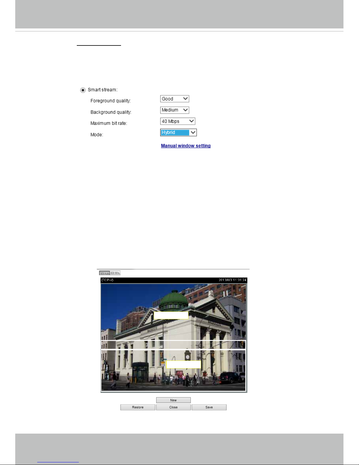
VIVOTEK
User's Manual - 69
• Smart stream: Smart stream effectively reduces the quality of the whole or
the non-interested areas on a screen and therefore reduces the bandwidth
consumed.
X
ROI_0
X
ROI_0
Foreground
background
You can manually specify the video quality for the foreground and the
background areas.
Select an operation mode if Smart stream is preferred.
- Auto tracking: The Auto mode configures the whole screen into the
background area. The video quality of part of the screen returns to
normal when one or more objects move in that area. The remainder of
the screen where there are no moving objects (no pixel changes) will still
be transmitted in low-quality format.
- Manual: The Manual mode allows you to configure 3 ROI windows (the
Foreground areas) on the screen. Areas not included in any ROI
windows will be considered as the Background areas. The details in the
ROI areas will always be transmitted in a higher-quality video format.
As illustrated below, the upper screen may contain little details of your
interest, while the sidewalk on the lower screen is included in an ROI
window.
Page 74

VIVOTEK
70 - User's Manual
Foreground: higher-quality
Background: lower-quality
As the result, the lower screen is constantly displayed in high details,
while the upper half is transmitted using a lower-quality format. Although
the upper half is transmitted using a lower quality format, you still have an
awareness of what is happening on the whole screen.
- Hybrid: The major difference between the “Manual” mode and the “Hybrid”
mode is that:
In the “Hybrid“ mode, any objects entering the background area
will restore the video quality of the moving objects and the area
around them. The video quality of the associated background area is
immediately restored to normal to cover the moving objects.
In the “Manual” mode, the background area is always transmitted using
a low-quality format regardless of the activities inside.
You should also select the Maximum bit rate from the pull-down menu as the
threshold to contain the bandwidth consumption for both the high- and lowquality video sections in a smart stream.
Page 75

VIVOTEK
User's Manual - 71
If JPEG mode is selected, the Network Camera sends consecutive JPEG images to the client,
producing a moving effect similar to a lmstrip. Every single JPEG image transmitted guarantees
the same image quality, which in turn comes at the expense of variable bandwidth usage. Because
the media contents are a combination of JPEG images, no audio data is transmitted to the client.
There are three parameters provided in MJPEG mode to control the video performance:
■ Frame size
You can set up different video resolution for different viewing devices. For example, set a smaller
frame size and lower bit rate for remote viewing on mobile phones and a larger video size and
a higher bit rate for live viewing on web browsers. Note that a larger frame size takes up more
bandwidth.
■ Maximum frame rate
This limits the maximum refresh frame rate per second. Set the frame rate higher for smoother
video quality.
If the power line frequency is set to 50Hz (at the 5MP resolution), the frame rates are selectable
at 1fps, 2fps, 3fps, 5fps, 8fps, 10fps, and 15fps. If the power line frequency is set to 60Hz, the
frame rates are selectable at 1fps, 2fps, 3fps, 5fps, 8fps, 10fps, and 15fps. You can also select
Customize and manually enter a value. The frame rate will decrease if you select a higher
resolution.
■ Video quality
Refer to the previous page setting an average or upper bound threshold for controlling the
bandwidth consumed for transmitting motion jpegs. The conguration method is identical to that
for H.264.
For Constant Bit Rate and other settings, refer to the previous page for details.
►
Video quality and xed quality refers to the compression rate, so a lower value will produce higher
quality.
►
Converting high-quality video may signicantly increase the CPU loading, and you may encounter
streaming disconnection or video loss while capturing a complicated scene. In the event of
occurance, we suggest you customize a lower video resolution or reduce the frame rate to obtain
smooth video.
NOTE:
Page 76

VIVOTEK
72 - User's Manual
Media > Audio
Audio Settings
Mute: Select this option to disable audio transmission from the Network Camera to all clients. Note
that if muted, no audio data will be transmitted even if audio transmission is enabled on the Client
Settings page. In that case, the following message is displayed:
External microphone input: Select the gain of the external audio input according to ambient
conditions. Adjust the gain from +21 db (most sensitive) or -33 db (least sensitive).
Audio type: Select audio codec and the sampling bit rate .
■ G.711 also provides good sound quality and requires about 64Kbps. Select pcmu (μ-Law) or
pcma (A-Law) mode.
■ G.726 is a speech codec standard covering voice transmission at rates of 16, 24, 32, and 40kbit/
s.
When completed with the settings on this page, click Save to enable the settings.
Page 77
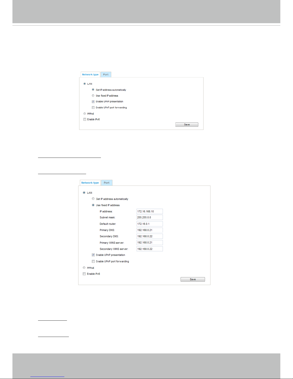
VIVOTEK
User's Manual - 73
Network > General settings
This section explains how to configure a wired network connection for the Network
Camera.
Network Type
LAN
Select this option when the Network Camera is deployed on a local area network (LAN) and is
intended to be accessed by local computers. The default setting for the Network Type is LAN.
Please rememer to click on the Save button when you complete the Network setting.
Get IP address automatically: Select this option to obtain an available dynamic IP address assigned
by the DHCP server each time the camera is connected to the LAN.
Use fixed IP address: Select this option to manually assign a static IP address to the Network
Camera.
1. You can make use of VIVOTEK Installation Wizard 2 on the software CD to easily set up the
Network Camera on LAN. Please refer to Software Installation on page 19 for details.
2. Enter the Static IP, Subnet mask, Default router, and Primary DNS provided by your ISP or
network administrator.
Subnet mask: This is used to determine if the destination is in the same subnet. The default value
is “255.255.255.0”.
Default router: This is the gateway used to forward frames to destinations in a different subnet.
Invalid router setting will disable the transmission to destinations across different subnets.
Page 78
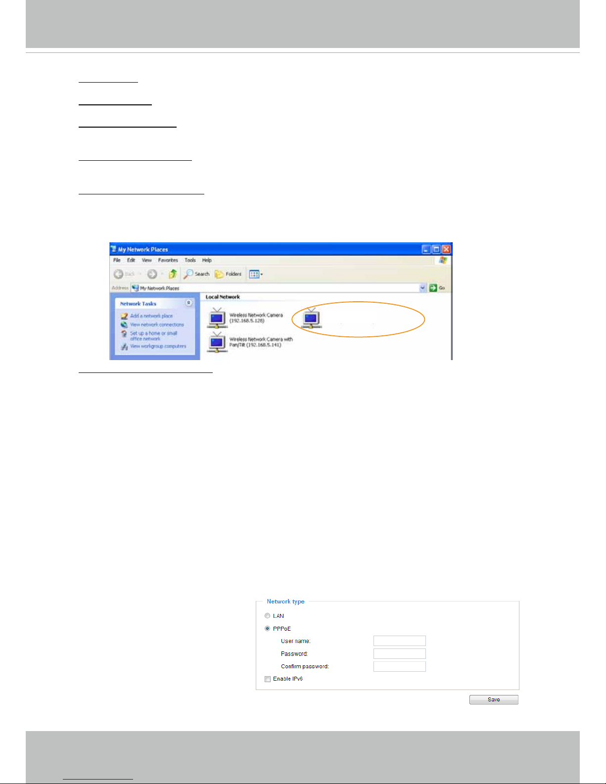
VIVOTEK
74 - User's Manual
Primary DNS: The primary domain name server that translates hostnames into IP addresses.
Secondary DNS: Secondary domain name server that backups the Primary DNS.
Primary WINS server: The primary WINS server that maintains the database of computer names
and IP addresses.
Secondary WINS server: The secondary WINS server that maintains the database of computer
names and IP addresses.
Enable UPnP presentation: Select this option to enable UPnP
TM
presentation for your Network
Camera so that whenever a Network Camera is presented to the LAN, the shortcuts to connected
Network Cameras will be listed in My Network Places. You can click the shortcut to link to the web
browser. Currently, UPnP
TM
is supported by Windows XP or later. Note that to utilize this feature,
please make sure the UPnP
TM
component is installed on your computer.
Enable UPnP port forwarding: To access the Network Camera from the Internet, select this option
to allow the Network Camera to open ports automatically on the router so that video streams can
be sent out from a LAN. To utilize of this feature, make sure that your router supports UPnP
TM
and
it is activated.
PPPoE (Point-to-point over Ethernet)
Select this option to congure your Network Camera to make it accessible from anywhere as long
as there is an Internet connection. Note that to utilize this feature, it requires an account provided
by your ISP.
Follow the steps below to acquire your Network Camera’s public IP address.
1. Set up the Network Camera on the LAN.
2. Go to Conguration > Event > Event settings > Add server (please refer to Add server on page
112) to add a new email or FTP server.
3. Go to Conguration > Event > Event settings > Add media (please refer to Add media on page
117).
Select System log so that you will receive the system log in TXT le format which contains the
Network Camera’s public IP address in your email or on the FTP server.
4. Go to Conguration > Network > General settings > Network type. Select PPPoE and enter the
user name and password provided by your ISP. Click Save to enable the setting.
5. The Network Camera will reboot.
6. Disconnect the power to the Network Camera; remove it from the LAN environment.
Mega-pixel Network Camera (192.168.5.151)
Page 79

VIVOTEK
User's Manual - 75
► If the default ports are already used by other devices connected to the same router, the Network
Camera will select other ports for the Network Camera.
► If UPnP
TM
is not supported by your router, you will see the following message:
Error: Router does not support UPnP port forwarding.
► Steps to enable the UPnP
TM
user interface on your computer:
Note that you must log on to the computer as a system administrator to install the UPnP
TM
components.
1. Go to Start, click Control Panel, then click Add or Remove Programs.
2. In the Add or Remove Programs dialog box, click Add/Remove Windows Components.
3.
In the Windows Components Wizard dialog box, select Networking Services and click
Details.
NOTE:
Page 80
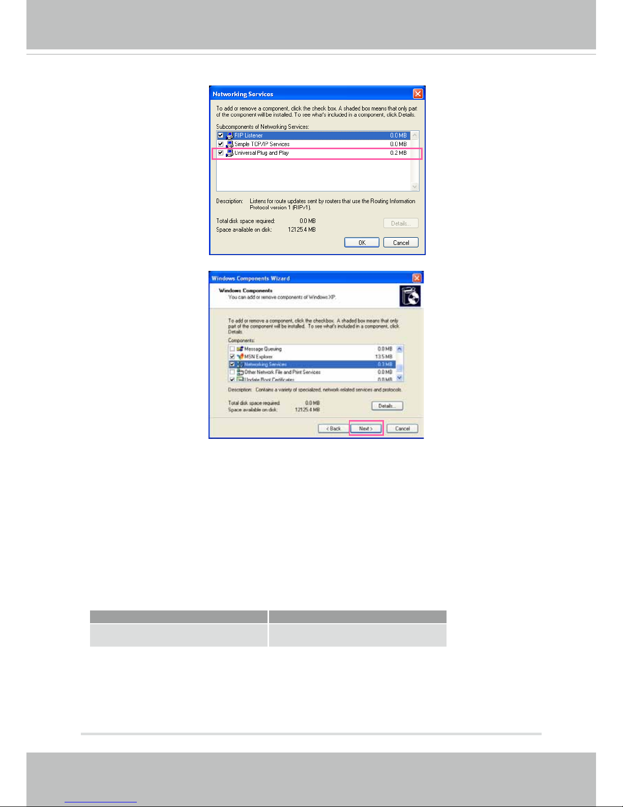
VIVOTEK
76 - User's Manual
4. In the Networking Services dialog box, select Universal Plug and Play and click OK.
5. Click Next in the following window.
6. Click Finish. UPnP
TM
is enabled.
► How does UPnP
TM
work?
UPnP
TM
networking technology provides automatic IP configuration and dynamic discovery of
devices added to a network. Services and capabilities offered by networked devices, such as
printing and file sharing, are available among each other without the need for cumbersome
network conguration. In the case of Network Cameras, you will see Network Camera shortcuts
under My Network Places.
► Enabling UPnP port forwarding allows the Network Camera to open a secondary HTTP port on
the router-not HTTP port-meaning that you have to add the secondary HTTP port number to the
Network Camera’s public address in order to access the Network Camera from the Internet. For
example, when the HTTP port is set to 80 and the secondary HTTP port is set to 8080, refer to
the list below for the Network Camera’s IP address.
From the Internet In LAN
http://203.67.124.123:8080 http://192.168.4.160 or
http://192.168.4.160:8080
► If the PPPoE settings are incorrectly congured or the Internet access is not working, restore
the Network Camera to factory default; please refer to Restore on page 48 for details. After the
Network Camera is reset to factory default, it will be accessible on the LAN.
Page 81

VIVOTEK
User's Manual - 77
Enable IPv6
Select this option and click Save to enable IPv6 settings.
Please note that this only works if your network environment and hardware equipment support
IPv6. The browser should be Microsoft
®
Internet Explorer 6.5, Mozilla Firefox 3.0 or above.
When IPv6 is enabled, by default, the network camera will listen to router advertisements and be
assigned with a link-local IPv6 address accordingly.
IPv6 Information: Click this button to obtain the IPv6 information as shown below.
If your IPv6 settings are successful, the IPv6 address list will be listed in the pop-up window. The
IPv6 address will be displayed as follows:
Link-global IPv6 address/network mask
Link-local IPv6 address/network mask
Refers to Ethernet
Page 82
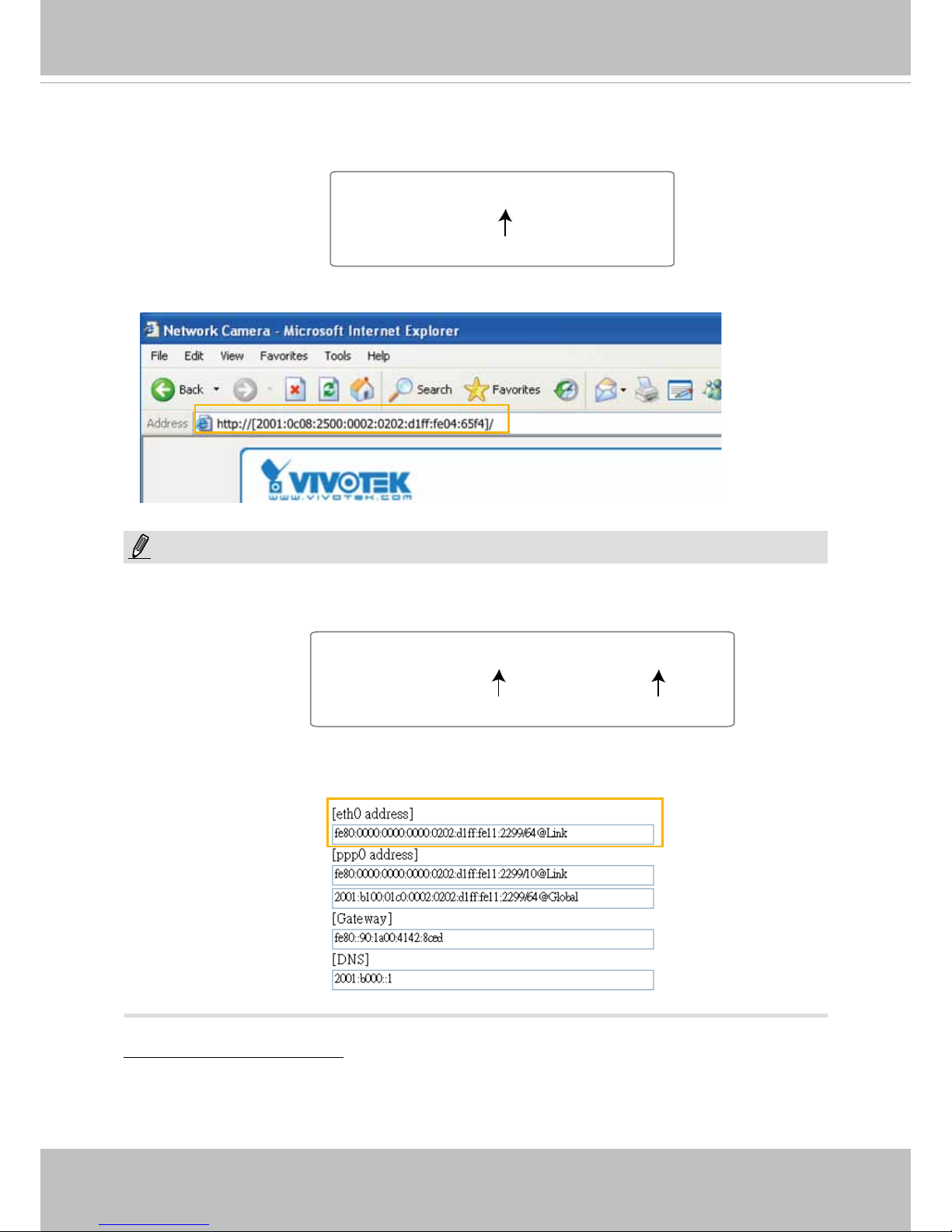
VIVOTEK
78 - User's Manual
Please follow the steps below to link to an IPv6 address:
1. Open your web browser.
2. Enter the link-global or link-local IPv6 address in the address bar of your web browser.
3. The format should be:
4. Press Enter on the keyboard or click Refresh button to refresh the webpage.
For example:
► If you have a Secondary HTTP port (the default value is 8080), you can also link to the webpage
using the following address format: (Please refer to HTTP streaming on page 81 for detailed
information.)
► If you choose PPPoE as the Network Type, the [PPP0 address] will be displayed in the IPv6
information column as shown below.
Manually setup the IP address: Select this option to manually set up IPv6 settings if your network
environment does not have DHCPv6 server and router advertisements-enabled routers. If
you check this item, the following blanks will be displayed for you to enter the corresponding
information:
http://[2001:0c08:2500:0002:0202:d1ff:fe04:65f4]/
IPv6 address
http://[2001:0c08:2500:0002:0202:d1ff:fe04:65f4]/:8080
IPv6 address
Secondary HTTP port
NOTE:
Page 83
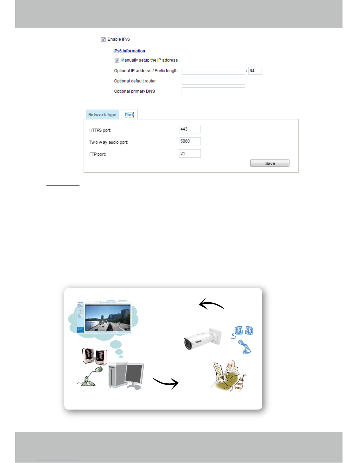
VIVOTEK
User's Manual - 79
Port
HTTPS port: By default, the HTTPS port is set to 443. It can also be assigned to another port
number between 1025 and 65535.
Two way audio port: By default, the two way audio port is set to 5060. Also, it can also be assigned
to another port number between 1025 and 65535.
The Network Camera supports two way audio communication so that operators can transmit and
receive audio simultaneously. By using the Network Camera’s built-in or external microphone and
an external speaker, you can communicate with people around the Network Camera.
Note that as JPEG only transmits a series of JPEG images to the client, to enable the two-way
audio function, make sure the video mode is set to "H.264" on the Media > Video > Stream settings
page and the media option is set to “Media > Video > Stream settings” on the Client Settings page.
Please refer to Client Settings on page 33 and Stream settings on page 67.
Audio transmitted from operators
Audio transmitted to operators
America
Taiwan
Page 84

VIVOTEK
80 - User's Manual
FTP port: The FTP server allows the user to save recorded video clips. You can utilize VIVOTEK's
Installation Wizard 2 to upgrade the rmware via FTP server. By default, the FTP port is set to 21.
It also can be assigned to another port number between 1025 and 65535.
2011/03/09 17:08:56
Mute
Mic Volume
Talk Button
Video (TCP-AV)
Audio is being transmitted to the Network Camera
Click to enable audio transmission to the Network Camera; click to adjust the volume of
microphone; click
to turn off the audio. To stop talking, click again.
Page 85
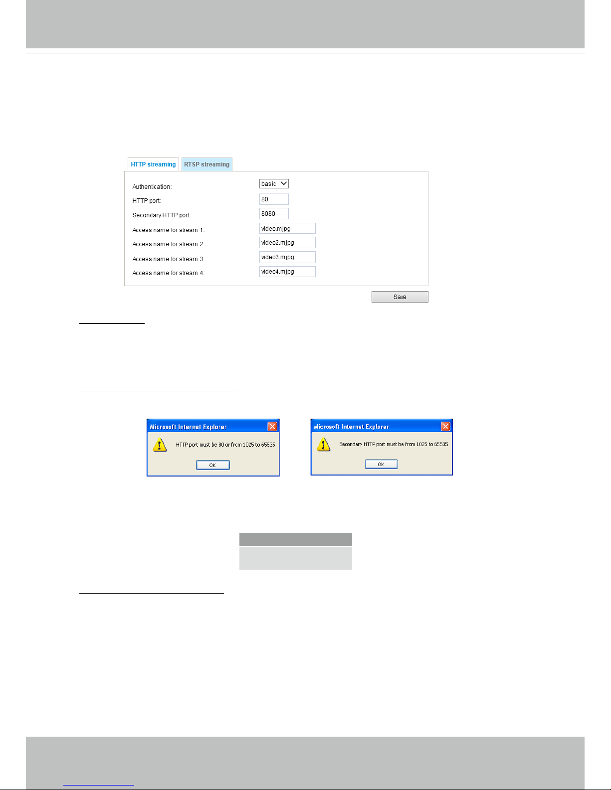
VIVOTEK
User's Manual - 81
Network > Streaming protocols
HTTP streaming
To utilize HTTP authentication, make sure that your have set a password for the Network Camera
rst; please refer to Security > User account on page 91 for details.
Authentication: Depending on your network security requirements, the Network Camera provides
two types of security settings for an HTTP transaction: basic and digest.
If basic authentication is selected, the password is sent in plain text format and there can be
potential risks of being intercepted. If digest authentication is selected, user credentials are
encrypted using MD5 algorithm and thus provide better protection against unauthorized accesses.
HTTP port / Secondary HTTP port: By default, the HTTP port is set to 80 and the secondary HTTP
port is set to 8080. They can also be assigned to another port number between 1025 and 65535. If
the ports are incorrectly assigned, the following warning messages will be displayed:
To access the Network Camera on the LAN, both the HTTP port and secondary HTTP port can
be used to access the Network Camera. For example, when the HTTP port is set to 80 and the
secondary HTTP port is set to 8080, refer to the list below for the Network Camera’s IP address.
Access name for stream 1 ~ 4: This Network camera supports multiple streams simultaneously.
The access name is used to identify different video streams. Users can click Media > Video >
Stream settings to set up the video quality of linked streams. For more information about how to
set up the video quality, please refer to Stream settings on page 64.
When using Mozilla Firefox to access the Network Camera and the video mode is set to JPEG,
users will receive video comprised of continuous JPEG images. This technology, known as “server
push”, allows the Network Camera to feed live pictures to Mozilla Firefox.
On the LAN
http://192.168.4.160 or
http://192.168.4.160:8080
Page 86
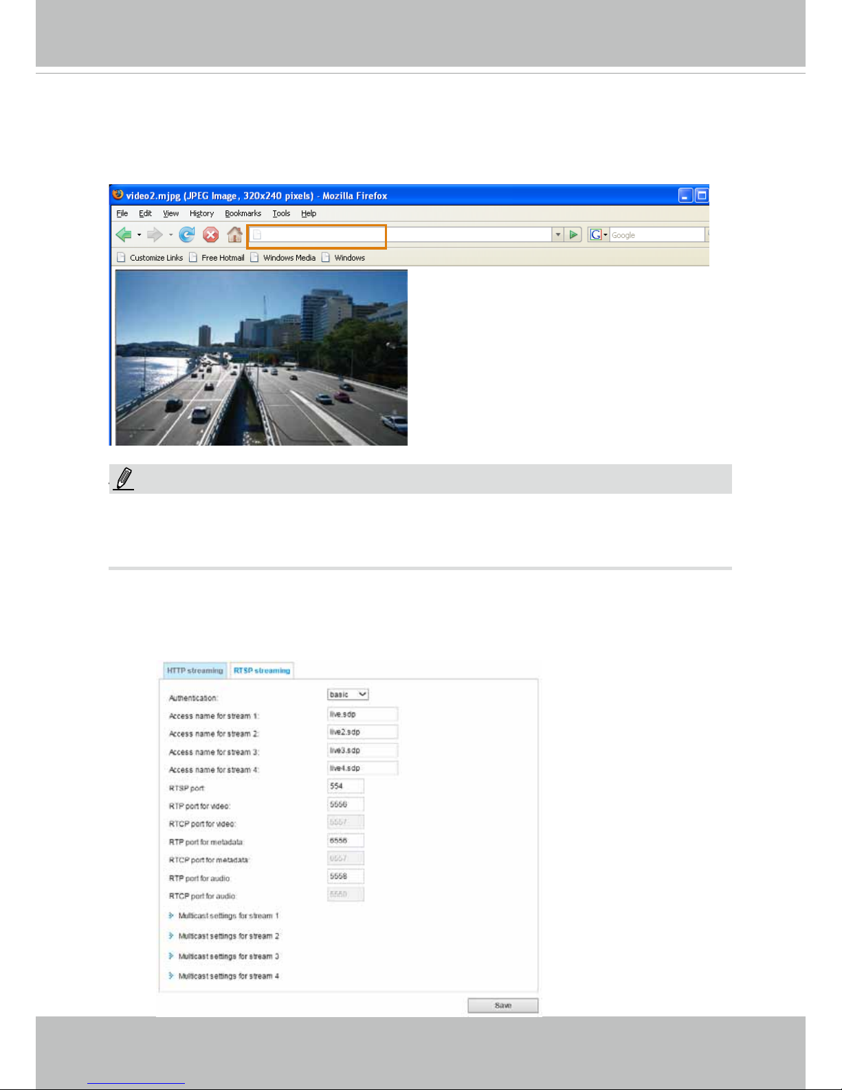
VIVOTEK
82 - User's Manual
URL command -- http://<ip address>:<http port>/<access name for stream 1, 2, 3 or 4>
For example, when the Access name for stream 2 is set to video2.mjpg:
1. Launch Mozilla Firefox or Netscape.
2. Type the above URL command in the address bar. Press Enter.
3. The JPEG images will be displayed in your web browser.
NOTE
► Microsoft
®
Internet Explorer does not support server push technology; therefore, you will not be
able to access a video stream using http://<ip address>:<http port>/<access name for stream 1,
2, 3, or 4> .
RTSP Streaming
To utilize RTSP streaming authentication, make sure that you have set a password for controlling
the access to video stream rst. Please refer to Security > User account on page 91 for details.
http://192.168.5.151/video2.mjpg
NOTE:
Page 87
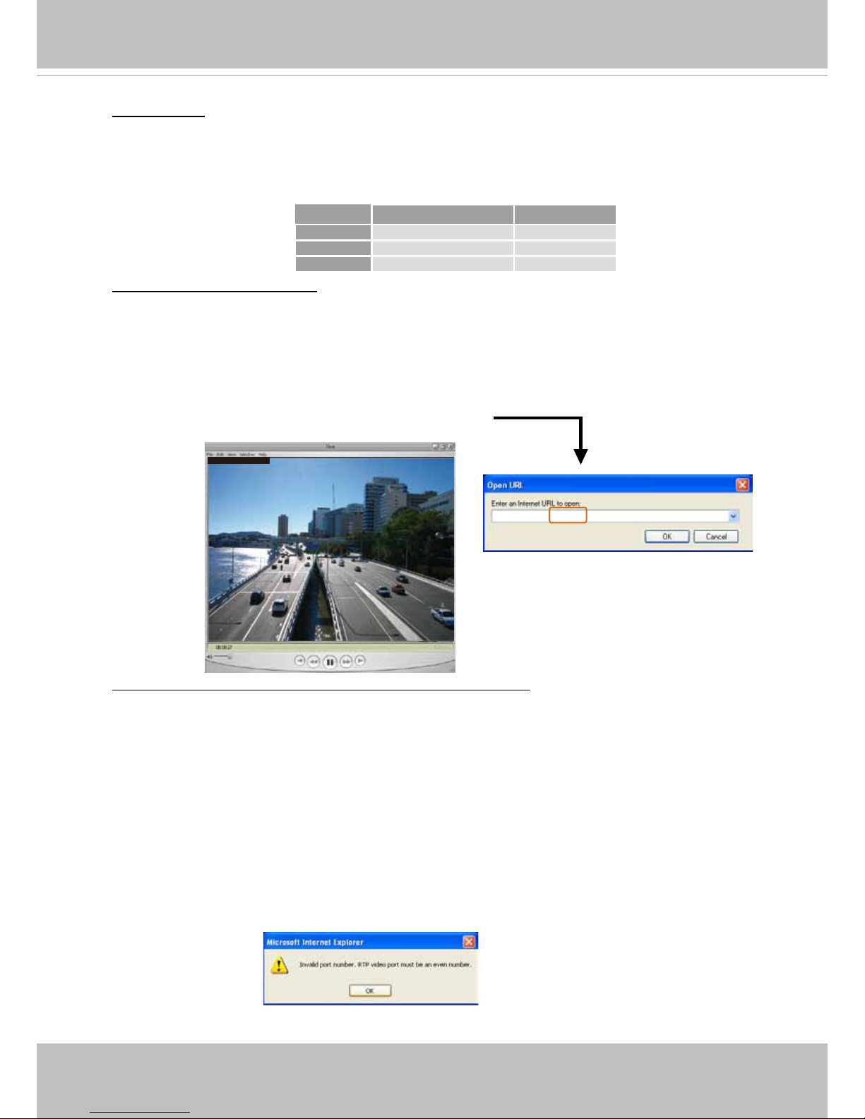
VIVOTEK
User's Manual - 83
Authentication: Depending on your network security requirements, the Network Camera provides
three types of security settings for streaming via RTSP protocol: disable, basic, and digest.
If basic authentication is selected, the password is sent in plain text format, but there can be
potential risks of it being intercepted. If digest authentication is selected, user credentials are
encrypted using MD5 algorithm, thus providing better protection against unauthorized access.
The availability of the RTSP streaming for the three authentication modes is listed below:
Access name for stream 1 ~ 3: This Network camera supports multiple streams simultaneously.
The access name is used to differentiate the streaming source.
If you want to use an RTSP player to access the Network Camera, you have to set the video mode
to H.264 and use the following RTSP URL command to request transmission of the streaming data.
rtsp://<ip address>:<rtsp port>/<access name for stream 1 to 3>
For example, when the access name for stream 1 is set to live.sdp:
1. Launch an RTSP player.
2. Choose File > Open URL. A URL dialog box will pop up.
3. Type the above URL command in the text box.
4. The live video will be displayed in your player as shown
below.
RTSP port /RTP port for video, audio/ RTCP port for video, audio
■ RTSP (Real-Time Streaming Protocol) controls the delivery of streaming media. By default, the
port number is set to 554.
■ The RTP (Real-time Transport Protocol) is used to deliver video and audio data to the clients. By
default, the RTP port for video is set to 5556.
■ The RTCP (Real-time Transport Control Protocol) allows the Network Camera to transmit the
data by monitoring the Internet trafc volume. By default, the RTCP port for video is set to 5557.
The ports can be changed to values between 1025 and 65535. The RTP port must be an even
number and the RTCP port is the RTP port number plus one, and thus is always an odd number.
When the RTP port changes, the RTCP port will change accordingly.
If the RTP ports are incorrectly assigned, the following warning message will be displayed:
rtsp://192.168.5.151:554/live.sdp
Quick Time player VLC
Disable O O
Basic O O
Digest O X
Video 16:38:01 2012/01/25
Page 88
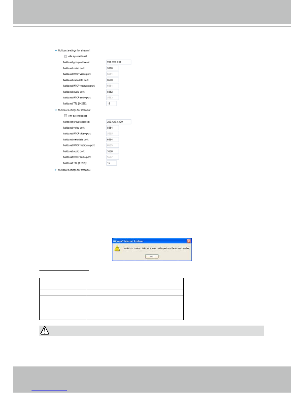
VIVOTEK
84 - User's Manual
Multicast settings for streams: Click the items to display the detailed configuration information.
Select the Always multicast option to enable multicast for video streams.
Unicast video transmission delivers a stream through point-to-point transmission; multicast, on the
other hand, sends a stream to the multicast group address and allows multiple clients to acquire
the stream at the same time by requesting a copy from the multicast group address. Therefore,
enabling multicast can effectively save Internet bandwith.
The ports can be changed to values between 1025 and 65535. The multicast RTP port must be an
even number and the multicast RTCP port number is the multicast RTP port number plus one, and
thus is always odd. When the multicast RTP port changes, the multicast RTCP port will change
accordingly.
If the multicast RTP video ports are incorrectly assigned, the following warning message will be
displayed:
Multicast TTL [1~255]: The multicast TTL (Time To Live) is the value that tells the router the range
a packet can be forwarded.
Initial TTL Scope
0 Restricted to the same host
1 Restricted to the same subnetwork
32 Restricted to the same site
64 Restricted to the same region
128 Restricted to the same continent
255 Unrestricted in scope
IMPORTANT:
The Multicast metadata port is utilized by VIVOTEK VADP modules to transfer video analytics
results, PTZ stream, textual data, and event messages between the camera and the client side
running and observing the video analysis. If your client side computer is located outside the local
network, you may need to open the associated TCP port on routers and rewall.
Page 89

VIVOTEK
User's Manual - 85
Network > DDNS
This section explains how to congure the dynamic domain name service for the Network
Camera. DDNS is a service that allows your Network Camera, especially when assigned
with a dynamic IP address, to have a xed host and domain name.
Express link
Express Link is a free service provided by VIVOTEK server, which allows users to register
a domain name for a network device. One URL can only be mapped to one MAC address.
This service will examine if the host name is valid and automatically open a port on your
router. If using DDNS, the user has to manually congure UPnP port forwarding. Express
Link is more convenient and easier to set up.
Please follow the steps below to enable Express Link:
1. Make sure that your router supports UPnP port forwarding and it is activated.
2. Check Enable express link.
3. Enter a host name for the network device and click Save. If the host name has been used by
another device, a warning message will show up. If the host name is valid, it will display a
message as shown below.
https://0002D1123456.2bthere.net
2010/12/10 17:08:56
Page 90

VIVOTEK
86 - User's Manual
Manual setup
DDNS: Dynamic domain name service
Enable DDNS: Select this option to enable the DDNS setting.
Provider: Select a DDNS provider from the provider drop-down list.
VIVOTEK offers Safe100.net, a free dynamic domain name service, to VIVOTEK customers. It
is recommended that you register Safe100.net to access VIVOTEK’s Network Cameras from the
Internet. Additionally, we offer other DDNS providers, such as Dyndns.org(Dynamic), Dyndns.
org(Custom), TZO.com, DHS.org, CustomSafe100, dyn-interfree.it.
Note that before utilizing this function, please apply for a dynamic domain account rst.
■ Safe100.net
1. In the DDNS column, select Safe100.net from the drop-down list. Click I accept after reviewing
the terms of the Service Agreement.
2. In the Register column, ll in the Host name (xxxx.safe100.net), Email, Key, and Conrm Key,
and click Register. After a host name has been successfully created, a success message will
be displayed in the DDNS Registration Result column.
3. Click Copy and all the registered information will automatically be uploaded to the corresponding
elds in the DDNS column at the top of the page as seen in the picture.
[Register] Successfully Your account information has
been mailed to registered e-mail address
Page 91

VIVOTEK
User's Manual - 87
[Register] Successfully Your account information has
been mailed to registered e-mail address
4. Select Enable DDNS and click Save to enable the setting.
■ CustomSafe100
VIVOTEK offers documents to establish a CustomSafe100 DDNS server for distributors and
system integrators. You can use CustomSafe100 to register a dynamic domain name if your
distributor or system integrators offer such services.
1. In the DDNS column, select CustomSafe100 from the drop-down list.
2. In the Register column, ll in the Host name, Email, Key, and Conrm Key; then click Register.
After a host name has been successfully created, you will see a success message in the DDNS
Registration Result column.
3. Click Copy and all for the registered information will be uploaded to the corresponding elds in
the DDNS column.
4. Select Enable DDNS and click Save to enable the setting.
Forget key: Click this button if you have forgotten the key to Safe100.net or CustomSafe100. Your
account information will be sent to your email address.
Refer to the following links to apply for a dynamic domain account when selecting other
DDNS providers:
■ Dyndns.org(Dynamic) / Dyndns.org(Custom): visit http://www.dyndns.com/
Page 92
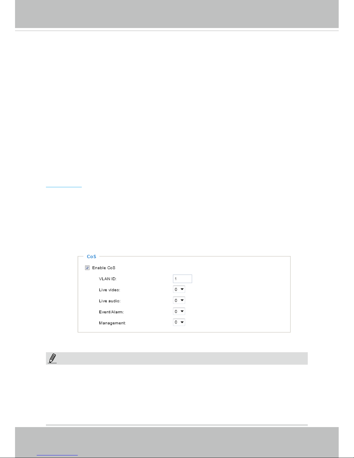
VIVOTEK
88 - User's Manual
Network > QoS (Quality of Service)
Quality of Service refers to a resource reservation control mechanism, which guarantees a certain
quality to different services on the network. Quality of service guarantees are important if the
network capacity is insufcient, especially for real-time streaming multimedia applications. Quality
can be dened as, for instance, a maintained level of bit rate, low latency, no packet dropping, etc.
The following are the main benets of a QoS-aware network:
■
The ability to prioritize trafc and guarantee a certain level of performance to the data ow.
■
The ability to control the amount of bandwidth each application may use, and thus provide higher
reliability and stability on the network.
Requirements for QoS
To utilize QoS in a network environment, the following requirements must be met:
■
All network switches and routers in the network must include support for QoS.
■
The network video devices used in the network must be QoS-enabled.
QoS models
CoS (the VLAN 802.1p model)
IEEE802.1p denes a QoS model at OSI Layer 2 (Data Link Layer), which is called CoS, Class of
Service. It adds a 3-bit value to the VLAN MAC header, which indicates the frame priority level from
0 (lowest) to 7 (highest). The priority is set up on the network switches, which then use different
queuing disciplines to forward the packets.
Below is the setting column for CoS. Enter the VLAN ID of your switch (0~4095) and choose the
priority for each application (0~7).
If you assign Video the highest level, the switch will handle video packets rst.
► A VLAN Switch (802.1p) is required. Web browsing may fail if the CoS setting is incorrect.
►The Class of Service technologies do not guarantee a level of service in terms of bandwidth
and delivery time; they offer a "best-effort." Users can think of CoS as "coarsely-grained" trafc
control and QoS as "nely-grained" trafc control.
► Although CoS is simple to manage, it lacks scalability and does not offer end-to-end guarantees
since it is based on L2 protocol.
NOTE:
Page 93
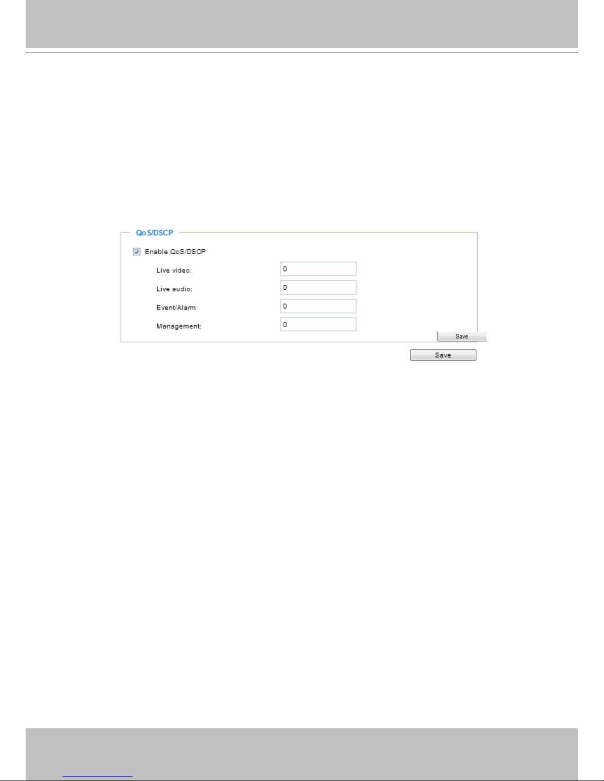
VIVOTEK
User's Manual - 89
QoS/DSCP (the DiffServ model)
DSCP-ECN denes QoS at Layer 3 (Network Layer). The Differentiated Services (DiffServ) model
is based on packet marking and router queuing disciplines. The marking is done by adding a eld
to the IP header, called the DSCP (Differentiated Services Codepoint). This is a 6-bit field that
provides 64 different class IDs. It gives an indication of how a given packet is to be forwarded,
known as the Per Hop Behavior (PHB). The PHB describes a particular service level in terms of
bandwidth, queueing theory, and dropping (discarding the packet) decisions. Routers at each
network node classify packets according to their DSCP value and give them a particular forwarding
treatment; for example, how much bandwidth to reserve for it.
Below are the setting options of DSCP (DiffServ Codepoint). Specify the DSCP value for each
application (0~63).
Page 94
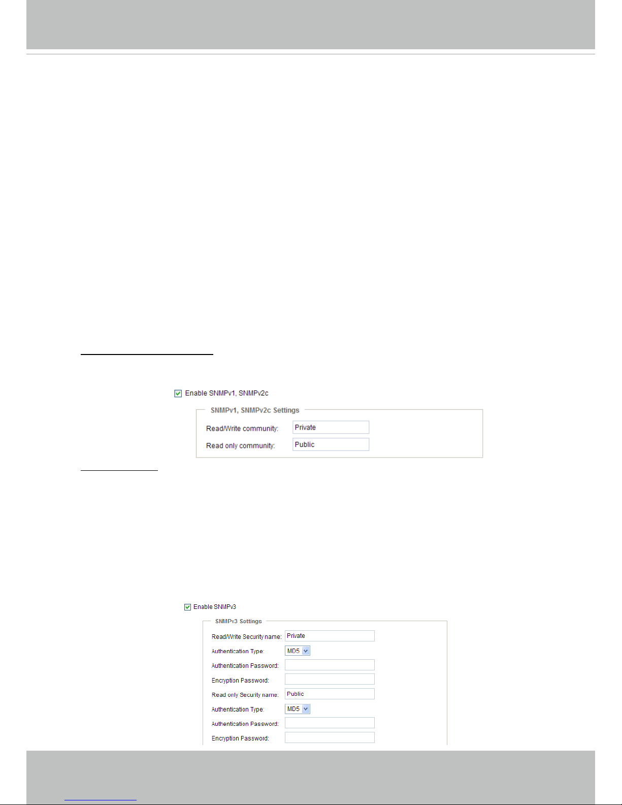
VIVOTEK
90 - User's Manual
Network > SNMP
(Simple Network Management Protocol)
This section explains how to use the SNMP on the network camera. The Simple Network
Management Protocol is an application layer protocol that facilitates the exchange of
management information between network devices. It helps network administrators to
remotely manage network devices and nd, solve network problems with ease.
■ The SNMP consists of the following three key components:
1. Manager: Network-management station (NMS), a server which executes applications that
monitor and control managed devices.
2. Agent: A network-management software module on a managed device which transfers the status
of managed devices to the NMS.
3. Managed device: A network node on a managed network. For example: routers, switches,
bridges, hubs, computer hosts, printers, IP telephones, network cameras, web server, and
database.
Before conguring SNMP settings on the this page, please enable your NMS rst.
SNMP Conguration
Enable SNMPv1, SNMPv2c
Select this option and enter the names of Read/Write community and Read Only community
according to your NMS settings.
Enable SNMPv3
This option contains cryptographic security, a higher security level, which allows you to set the
Authentication password and the Encryption password.
■ Security name: According to your NMS settings, choose Read/Write or Read Only and enter the
community name.
■ Authentication type: Select MD5 or SHA as the authentication method.
■ Authentication password: Enter the password for authentication (at least 8 characters).
■ Encryption password: Enter a password for encryption (at least 8 characters).
Page 95

VIVOTEK
User's Manual - 91
Security > User accounts
This section explains how to enable password protection and create multiple accounts.
Root Password
The administrator account name is “root”, which is permanent and can not be deleted. If you
want to add more accounts in the Manage User column, please apply the password for the “root”
account rst.
1. Type the password identically in both text boxes, then click Save to enable password protection.
2. A window will be prompted for authentication; type the correct user’s name and password in their
respective elds to access the Network Camera.
Privilege Management
PTZ control: You can modify the management privilege for operators or viewers. Select or deselect
the checkboxes, then click Save to enable the settings. If you give Viewers the privilege, Operators
will also have the ability to control the Network Camera through the main page. (Please refer to
Conguration on page 38).
Allow anonymous viewing: If you check this item, any client can access the live stream without
entering a User ID and Password.
Account Management
Administrators can create up to 20 user accounts.
1. Input the new user’s name and password.
2. Select the privilege level for the new user account. Click Add to enable the setting.
Access rights are sorted by user privilege (Administrator, Operator, and Viewer). Only
administrators can access the Configuration page. Although operators cannot access the
Conguration page, they can use the URL Commands to get and set the value of parameters. For
more information, please refer to URL Commands of the Network Camera on page 141. Viewers
can only access the main page for live viewing.
Here you also can change a user’s access rights or delete user accounts.
1. Select an existing account to modify.
2. Make necessary changes and click Update or Delete to enable the setting.
Page 96

VIVOTEK
92 - User's Manual
Security > HTTPS
(Hypertext Transfer Protocol over SSL)
This section explains how to enable authentication and encrypted communication over
SSL (Secure Socket Layer). It helps protect streaming data transmission over the Internet
on higher security level.
Create and Install Certicate Method
Before using HTTPS for communication with the Network Camera, a Certicate must be created
rst. There are three ways to create and install a certicate:
Create self-signed certificate
1. Select this option from a pull-down menu.
2. In the rst column, select Enable HTTPS secure connection, then select a connection option:
“HTTP & HTTPS” or “HTTPS only”.
3. Click Create certicate to generate a certicate.
4. The Certicate Information will automatically be displayed as shown below. You can click Certi-
cate properties to view detailed information about the certicate.
Page 97

VIVOTEK
User's Manual - 93
5. Click Save to preserve your conguration, and your current session with the camera will change
to the encrypted connection.
6. If your web session does not automatically change to an encrypted HTTPS session, click Home
to return to the main page. Change the URL address from “http://” to “https://“ in the address bar
and press Enter on your keyboard. Some Security Alert dialogs will pop up. Click OK or Yes to
enable HTTPS.
https://192.168.5.151/index.html
https://
Page 98

VIVOTEK
94 - User's Manual
Create certificate request and install
1. Select the option from the Method pull-down menu.
2. Click Create certicate to proceed.
3. The following information will show up in a pop-up window after clicking Create. Then click Save
to generate the certicate request.
4. The Certicate request window will prompt.
If you see the following Information bar, click OK and click on the Information bar at the top of
the page to allow pop-ups.
Page 99
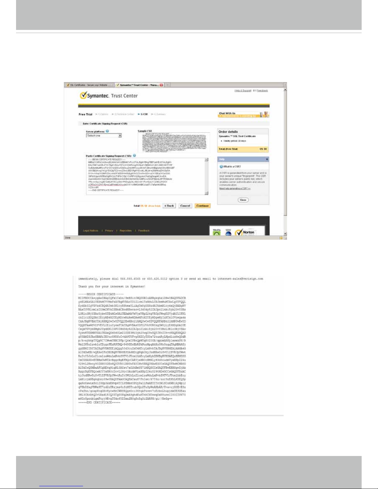
VIVOTEK
User's Manual - 95
5. Look for a trusted certicate authority, such as Symantec’s VeriSign Authentication Services, that
issues digital certicates. Sign in and purchase the SSL certication service. Copy the certicate
request from your request prompt and paste it in the CA’s signing request window. Proceed with
the rest of the process as CA’s instructions on their webpage.
6. Once completed, your SSL certicate should be delivered to you via an email or other means.
Copy the contents of the certicate in the email and paste it in a text/HTML/hex editor/converter,
such as IDM Computer Solutions’ UltraEdit.
Page 100

VIVOTEK
96 - User's Manual
7. Open a new edit, paste the certicate contents, and press ENTER at the end of the contents to
add an empty line.
8. Convert le format from DOS to UNIX. Open File menu > Conversions > DOS to Unix.
 Loading...