

Page 1
FE8191
Fisheye
Network Camera
Quick Installation Guide
繁中 日本語
English
Dansk
Indonesia
簡中
Français
Deutsch
Español Português
360° Surround View • PoE
Italiano
Türkçe
Polski
Русский
Česky Svenska
Dutch
Page 2
Warning Before Installation
English
Power off the Network Camera as
soon as smoke or unusual odors are
detected.
Do not place the Network Camera on
unsteady surfaces.
Do not insert sharp or tiny objects
into the Network Camera.
1
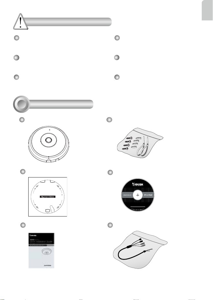
Package Contents
FE8191
Alignment Sticker
D
r
i
l
l
h
o
l
e
e
l
o
h
l
l
i
r
D
Refer to your user's manual for
the operating temperature.
Do not touch the Network Camera
during a lightning storm.
Do not drop the Network Camera.
Screws / Anchors / Cable tie
Software CD
5
1
0
G
0
0
1
0
2
0
Quick Installation Guide
Power & I/O Cables
(Sold Separately in US & Canada)
EN - 1
Page 3
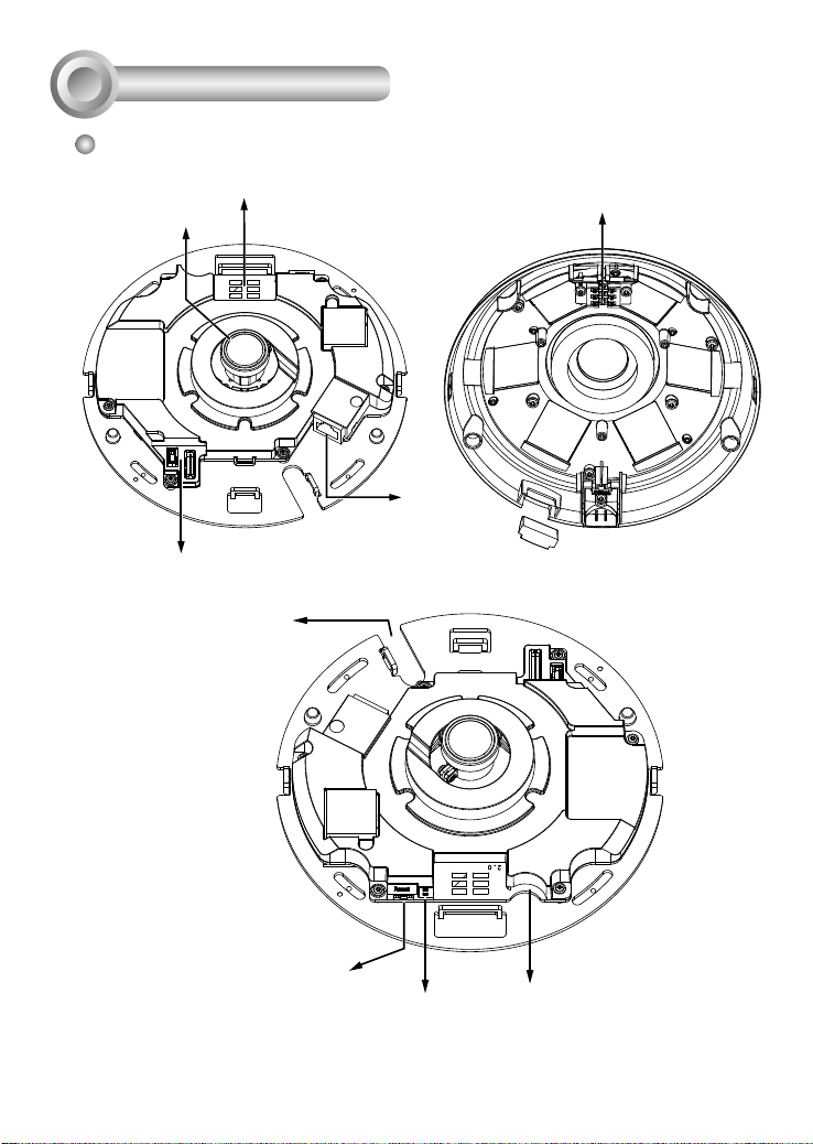
Physical Description
2
Inner View
Contacts
Lens
J7
J6
Headers
Cabling Cutout
Contacts for microphone
Ethernet 10/100 RJ45 Socket
Reset Button
Status LEDs
EN - 2
MicroSD/SDHC/SDXC Card Slot
Page 4
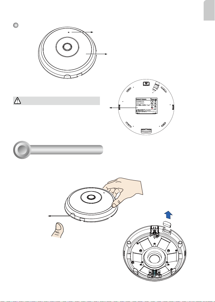
Outer View
English
Built-in Microphone
Dome Cover
IMPORTANT:
Record the MAC address under the camera
base before installing the camera.
Hardware Installation
3
First, open the dome cover by pressing the release button. You may squeeze the opposite edge of
the dome cover if the dome cover does not come off easily. Then, follow the steps below to install the
camera to either a ceiling or a wall.
Release button
If you plan to route cables from the side of camera, remove the rubber slide cover from the dome cover.
8181
083236
Slide cover
EN - 3
Page 5

Connecting Ethernet Cable
& the Power and IO Cable
Connect the supplied power & IO cables if your
switch does not support PoE. Connect the white
header connectors to J6 and J7 on the camera.
Power & IO Cable
J7
J6
Connecting Cables
If you need to route cables through the side opening, proceed with the following:
1. Connect the Ethernet and the Power & IO cables. The Ethernet cable is user-supplied.
2. Use the included cable ties to secure the Ethernet and IO cable to the base plate. Insert the cable
ties through the vertical mounting tabs on the side of the plastic cover and on the edge of the
cabling cutout.
3. Arrange the cables neatly to avoid getting in the way when the dome cover is attached.
4. Cut the extra length from the cable tie.
If you route cables through a drill hole on
a wall/ceiling, simply route cables through
the cabling cutout.
Strain relief boot
Power and IO
cables
It is recommended to remove the strain relief boot if your Ethernet cable
comes with one.
Ethernet
EN - 4
Page 6

Ceiling or Wall Mount
1. Attach the supplied alignment sticker for the camera base to the a ceiling or wall.
2. Using the circles on the sticker, drill pilot holes into the ceiling. Then hammer the supplied plastic
anchors into the holes.
3. (Optional) Drill a cable hole on the ceiling/wall, and feed the cables through the hole.
4. Secure the camera base to the ceiling/wall with the supplied screws.
English
1
D
r
i
l
l
h
o
l
e
e
l
o
h
l
l
i
r
D
2
D
r
i
l
l
h
o
l
e
e
l
o
h
l
l
i
r
D
4
D
r
i
l
l
h
o
l
e
e
l
o
h
l
l
i
r
D
3
NOTE:
You may also install the camera to a U.S. standard 4 in. junction box.
You can align the camera’s curved slots with the mounting holes on
a junction box. Use diagonal mounting positions on the camera to
match those on a junction box.
EN - 5
Page 7

Attach the Dome Cover
Dome cover
Install the plastic dome cover by aligning the snap-
t tabs on the dome cover with the slotted tabs on the
camera base. Install the dome cover by pressing it
evenly to the camera base.
Make sure the dome cover and the base plate are
ush-aligned before pressing down. The dome cover is
secured using a snap-t mechanism.
Snap-t tabs
EN - 6
Page 8

4
Network Deployment
General Connection (without PoE)
1. Connect RJ45 Ethernet cable to a switch.
2. Connect the power cable from the Network Camera to a power outlet.
3. If you have external devices such as sensors and alarms, make the connection from the general
I/O terminal block.
L
I
N
POW
ER
C
O
LL
K
I
RECEIVE
S
ION
1
PARTITIO
2
3
N
4
5
1
English
3
+3V3
+3V3: Power, 3.3V DC
DO
DO: Digital Output
D I: Digital Input
D1
GND: Ground
GND
2
General I/O Terminal Block
Power Cord Socket (Black)
Microphone In (Pink)
Audio Out (Green)
IMPORTANT:
If DC power is preferred, it should comply with: O/P: 12VDC, 2A min., L.P.S. per IEC 60950-1.
EN - 7
Page 9

Power over Ethernet (PoE)
When using a PoE- enabled switch
The Network Camera is PoE-compliant, allowing transmission of power and data via a single Ethernet cable. Follow the below illustration to connect the Network Camera to a PoE-enabled switch via
Ethernet cable.
NOTE:
1. This equipment is only to be connected to PoE networks without routing to outside plants.
2. For PoE input, use only UL listed I.T.E. with PoE output.
L
I
N
POW
ER
PoE Switch (802.3af)
When using a non-PoE switch
Use a PoE power injector (optional) to connect between the Network Camera and a non-PoE switch.
K
C
O
LL
I
RECEIVE
S
ION
1
PARTITIO
2
3
N
4
5
EN - 8
PoE 802.3af Power
Injector (optional)
Non-PoE Switch
Page 10

Assigning an IP Address
5
1. Install “Installation Wizard 2” from the Software Utility directory on the software CD.
2. The program will conduct an analysis of your network environment. After your network is
analyzed, please click on the “Next” button to continue the program.
3. The program will search for VIVOTEK Video Receivers, Video Servers, and Network Cameras on
the same LAN.
4. After a brief search, the main installer window will pop up. Double-click on the MAC address that
matches the one printed on the camera label or the serial number on the package box label to
open a browser management session with the Network Camera.
6
Ready to Use
1. A browser session with the Network Camera should prompt as shown below.
2. You should be able to see live video from your camera. You may also install the 32-channel recording software from the software CD in a deployment consisting of multiple cameras. For its installation details, please refer to its related documents.
English
For further setup, please refer to the user's manual on the software CD.
NOTE:
If you encounter problems with displaying live view or the onscreen plug-in control, you may try to
remove the plug-ins that might have been installed on your computer. Remove the following folder: C:\
Program Files (x86)\Camera Stream Controller\.
EN - 9
Page 11

What Is Covered : This warranty covers any hardware defects in materials or
workmanship, with the exceptions stated below.
How Long Coverage Lasts: This warranty lasts fo r THIRTY-SIX MONTHS from
the date of purchase by the original end-user customer.
What Is Not Covered : This warranty does not cover cosmetic damage or any
other damage or defect caused by abuse, misuse, neglect, use in violation of
instructions, repair by an unauthorized third part y, or an act of God. Also, if serial
numbers have been altered, defaced, or removed. Furthe r, consequential and
incidental damages are not recoverable under this warranty.
What VIVOTEK Will Do: VIVOTEK will, in our sole discretion, repair or replace
any product that proves to be defective in material or workmanship. Any repair or
replaced part of the product will receive a THREE-MONTH warranty extension.
How To Get Service: Contact our authorized distributors in your region. Please
check our website (www .vivotek.com) for the information of an authorized
distributor near you.
Your Rights: SOME STATES DO NO T ALLOW EXCLUSION OR LIMIT ATION
OF CONSEQUENTIA L OR INCIDEN TAL DAMAGES, SO THE ABOVE EXCL USION OR LIMI TATION MAY NOT APPLY TO YOU. THIS W ARRANT Y GIVES
YOU SPECIFIC LEGAL RIGHTS, AND YOU MAY ALSO HAVE OTHER RIGHTS
WHICH VARY FROM STATE TO STATE.
VIVOTEK INC.
6F, No. 192, Lien-Cheng Rd., Chung-Ho,
Taipei County, Taiwan.
www.vivotek.com
1. Proof of the date of purchase is required. In the event you can not render such
document, warranty will commence from the date of manufacture.
2. Cosmetic damage will only be covered by this warranty if such damage has
been existed at the time of purchase.
AR - 168
Page 12

P/N:625028701G Rev.: 1.1
All specications are subject to change without notice.
c
Copyright 2015 VIVOTEK INC. All rights reserved.
VIVOTEK Europe
Randstad 22-133, 1316BW Almere, The Netherlands
T: +31(0)36-5298-434 E: saleseurope@vivotek.com
 Loading...