

Page 1
Page 2
Warning Before Installation
English
Power off the Network Camera
as soon as smoke or unusual
odors are detected.
Do not place the Network
Camera on unsteady surfaces.
Do not insert sharp or tiny
objects into the Network
Camera.
1
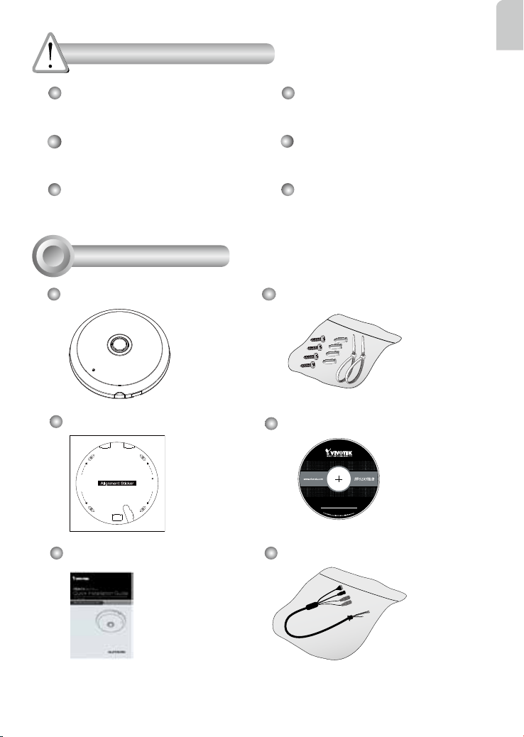
Package Contents
FE8174
Alignment Sticker
D
r
i
l
l
h
o
l
e
e
l
o
h
l
l
i
r
D
Refer to your user's manual
for the operating temperature.
Do not touch the Network
Camera during a lightning
storm.
Do not drop the Network
Camera.
Screws / Anchors / Cable tie
Software CD
5
1
0
G
0
0
1
0
2
0
Quick Installation Guide
Power & I/O Cables
(Sold Separately in US & Canada)
EN - 1
Page 3
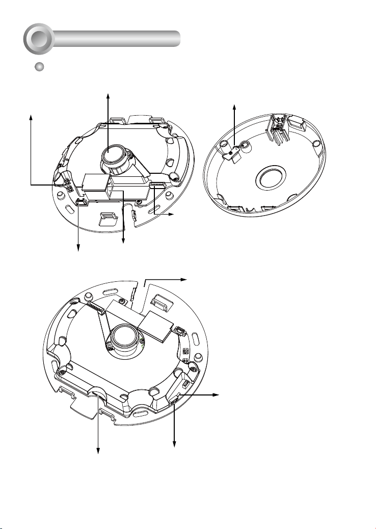
Physical Description
2
Inner View
Spring Contacts
(A)
Header (J7)
Lens
Ethernet 10/100 RJ45 Socket
Contacts for Internal Microphone
(B)
Header (J6)
Cabling Cutout
Reset Button
MicroSD/SDHC/SDXC Card Slot
Status LEDs
EN - 2
Page 4
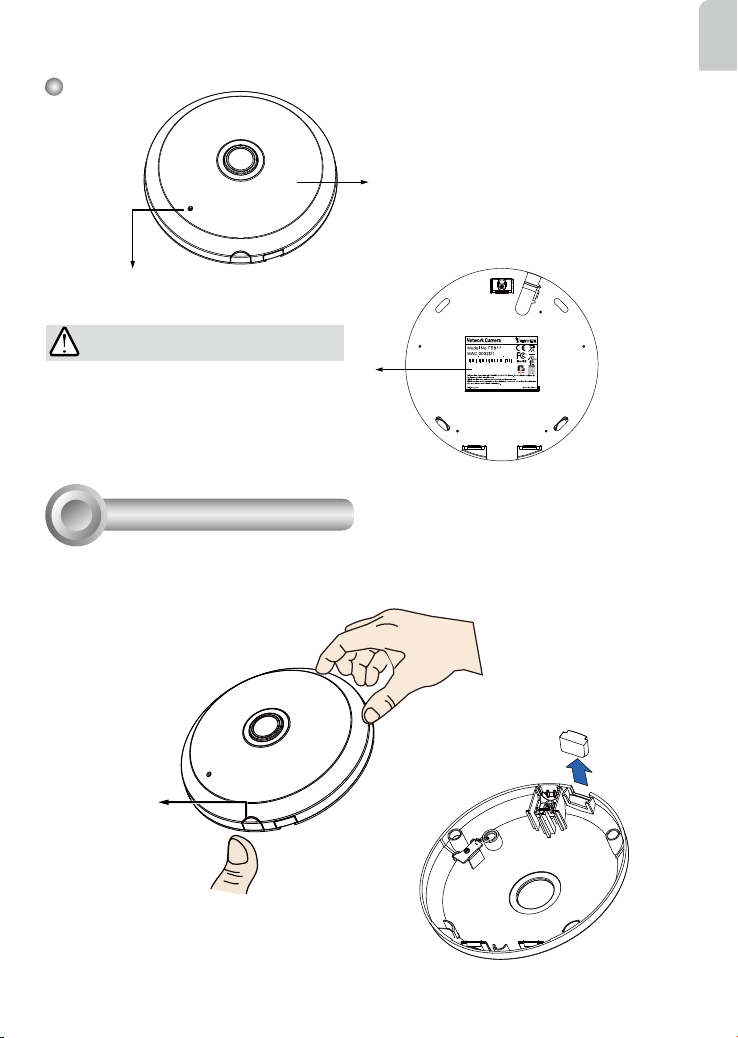
Outer View
Built-in Microphone
English
Dome Cover
IMPORTANT:
4
083236
Record the MAC address under the
camera base before installing the
camera.
Hardware Installation
3
First, open the dome cover by pressing the release button. You may squeeze the opposite edge of
the dome cover if the dome cover does not come off easily. Then, follow the steps below to install the
camera to either a ceiling or a wall.
Slide cover
Release button
If you plan to route cables from the side of camera, remove the rubber slide cover from the dome cover.
EN - 3
Page 5

Connecting Ethernet Cable
& the Power and IO Cable
Connect the supplied power & IO cables if your
switch does not support PoE. Connect the white
header connectors to J6 and J7 on the camera.
J7
Power & IO Cable
J6
Connecting Cables
If you need to route cables through the side opening, proceed with
the following:
1. Connect the Ethernet and the Power & IO cables. The Ethernet cable
is user-supplied.
2. Use an included cable tie to secure the Ethernet and IO cable to the base plate. Insert the cable
tie through the vertical mounting tab located on the edge of the cabling cutout.
3. Make a clearance between cables and the vertical mounting tab. Arrange the cables neatly to
avoid getting in the way when the dome cover is attached.
4. Cut the extra length from the cable tie.
If you route cables through a drill hole on
a wall/ceiling, simply route cables through
the cabling cutout.
Strain relief boot
Make a clearance
between cables and
the vertical tab
Ethernet
Power and IO
cables
It is recommended to remove the strain relief boot if your Ethernet cable
comes with one.
EN - 4
Page 6

Ceiling or Wall Mount
1. Attach the supplied alignment sticker for the camera base to the a ceiling or wall.
2. Using the circles on the sticker, drill pilot holes into the ceiling. Then hammer the supplied plastic
anchors into the holes.
3. (Optional) Drill a cable hole on the ceiling/wall, and feed the cables through the hole.
4. Secure the camera base to the ceiling/wall with the supplied screws.
English
1
D
r
i
l
l
h
o
l
e
e
l
o
h
l
l
i
r
D
2
D
r
i
l
l
h
o
l
e
e
l
o
h
l
l
i
r
D
4
D
r
i
l
l
h
o
l
e
e
l
o
h
l
l
i
r
D
3
NOTE:
You may also install the camera to a U.S. standard 4 in. junction box.
You can align the camera’s curved slots with the mounting holes on
a junction box. Use diagonal mounting positions on the camera to
match those on a junction box.
EN - 5
Page 7

Attach the Dome Cover
Dome cover
Install the plastic dome cover by aligning the snap-
t tabs on the dome cover with the slotted tabs on the
camera base. Install the dome cover by pressing it
evenly to the camera base.
Make sure the dome cover and the base plate are
ush-aligned before pressing down. The dome cover is
secured using a snap-t mechanism.
Slotted tabs
Snap-t tabs
EN - 6
Page 8

4
Network Deployment
General Connection (without PoE)
1. Connect RJ45 Ethernet cable to a switch.
2. Connect the power cable from the Network Camera to a power outlet.
3. If you have external devices such as sensors and alarms, make the connection from the general
I/O terminal block.
L
I
N
POW
ER
C
O
LL
K
I
RECEIVE
S
ION
1
PARTITIO
2
3
N
4
5
1
English
3
General I/O Terminal Block
Power Cord Socket (Black)
Microphone In (Pink)
Audio Out (Green)
NOTE:
If DC power is preferred, it should comply with: O/P:
12VDC, 1.5Amin., L.P.S. per IEC 60950-1.
+3V3
+3V3: Power, 3.3V DC
DO: Digital Output
DO
D I: Digital Input
D1
GND: Ground
GND
2
EN - 7
Page 9

Power over Ethernet (PoE)
When using a PoE- enabled switch
The Network Camera is PoE-compliant, allowing transmission of power and data via a single Ethernet cable. Follow the below illustration to connect the Network Camera to a PoE-enabled switch via
Ethernet cable.
NOTE:
1. This equipment is only to be connected to PoE networks
without routing to outside plants.
2. For PoE input, use only UL listed I.T.E. with PoE output.
L
I
N
POW
ER
PoE Switch
When using a non-PoE switch
Use a PoE power injector (optional) to connect between the Network Camera and a non-PoE switch.
K
C
O
LL
I
RECEIVE
S
ION
1
PARTITIO
2
3
N
4
5
PoE Power Injector
(optional)
EN - 8
L
I
N
POW
ER
K
C
O
LL
I
RECEIVE
S
ION
1
PARTITIO
2
3
4
5
Non-PoE Switch
N
Page 10

AR - 168
Page 11

 Loading...