

Page 1
FD9165-HT-A
Fixed Dome
FD9365-HTV-A, FD9365-EHTV-A
Network Camera
User’s Manual
2MP • IP66 (outdoor) • IK10 • Day & Night • Smart Motion Detection (H/T) • Smart VCA
Remote Focus (T) • WDR Pro II • Smart Stream III • SNV II • 50M Smart IR • Shock Detection
Rev. 1.0
Page 2

VIVOTEK
Table of Contents
Overview
Revision History ..................................................................................................................................................... 4
Read Before Use .................................................................................................................................................... 4
Package Contents .................................................................................................................................................. 7
Symbols and Statements in this Document ............................................................................................................ 7
Physical Description .............................................................................................................................................. 8
Hardware Installation (FD9165) ........................................................................................................................... 13
Software Installation ............................................................................................................................................. 17
Hardware Installation (FD9365) ........................................................................................................................... 23
Software Installation ............................................................................................................................................. 30
Network Deployment ............................................................................................................................................ 38
Ready to Use ........................................................................................................................................................ 39
Accessing the Network Camera
Using Web Browsers ............................................................................................................................................ 42
Using RTSP Players ............................................................................................................................................. 45
Using 3GPP-compatible Mobile Devices .............................................................................................................. 46
Using VIVOTEK Recording Software ................................................................................................................... 47
Main Page
Client Settings
Conguration
System > General settings ................................................................................................................................... 59
System > Homepage layout ................................................................................................................................ 61
System > Logs ..................................................................................................................................................... 64
System > Parameters .......................................................................................................................................... 67
System > Maintenance ......................................................................................................................................... 68
Media > Image ................................................................................................................................................... 72
Media > Video ...................................................................................................................................................... 86
Media > Video ...................................................................................................................................................... 87
Media > Video ...................................................................................................................................................... 88
Media > Audio....................................................................................................................................................... 97
Network > General settings .................................................................................................................................. 99
Network > Streaming protocols ........................................................................................................................ 106
Network > SNMP
Network > FTP ................................................................................................................................................... 117
Bonjour ............................................................................................................................................................... 118
Security > User accounts ................................................................................................................................... 119
Security > HTTPS
Security > Access List ...................................................................................................................................... 128
PTZ > PTZ settings ............................................................................................................................................ 134
Event > Event settings........................................................................................................................................ 138
Applications > Motion detection.......................................................................................................................... 152
Applications > Smart VCA .................................................................................................................................. 153
Applications > Tampering detection ................................................................................................................... 154
Applications > Audio detection ......................................................................................................................... 155
....................................................................................................................................................................
...........................................................................................................................
................................................................................................................................................................
.........................................................................................................................................................
...........................................................................................................................................................
(Simple Network Management Protocol) ..................................................................11 6
(Hypertext Transfer Protocol over SSL) ........................................................12
3
42
48
53
58
1
2 - User's Manual
Page 3

VIVOTEK
Applications > Shock detection ...............................................................................................................157
Applications > Package management - a.k.a., VADP (VIVOTEK Application Development Platform) ... 158
Recording > Recording settings .............................................................................................................. 161
Local storage > Storage management ..................................................................................................... 166
Local storage > Content management ..................................................................................................... 169
Appendix
URL Commands for the Network Camera ................................................................................................ 172
Technology License Notice ....................................................................................................................... 436
Electromagnetic Compatibility (EMC) .......................................................................................................437
....................................................................................................................................................
172
Overview
The 9165 and 9365 series is a camera line to come embedded with the Smart Motion
Detection feature. The Smart Motion detection, with Human detection and tunable time
lter, can eliminate the defects of traditional motion detection and facilitate the conguration
at a surveillance site.
To learn more about this feature, download its User Guide in:
http://download.vivotek.com/downloadfile/solutions/vadp/smart-motion-detection-manual_
en.pdf
A key feature in the Smart Motion detection is the Human detection. Based on a human
silhouette database and the rapid responses via an artificial neural network technology,
the Smart engine instantly recognizes human appearances in a video surveillance area.
Since humans are the objects of interest in the majority of video surceillance, the Human
detection feature enables users to quickly congure his installation.
With Human detection, light changes or swaying vegetation, vehicles passing by, or animal
activities in the scene are not taken as event triggers. Only human activities will trigger an
event. This helps reduce false alarms and the time and efforts for a camera conguration.
The 9365 series is an outdoor network camera capable of 1920 x 1080 resolution at 60
fps. With the most updated VIVOTEK SNV and WDR Pro technology, the 9365 series
is capable of capturing the highest quality images in both low light and high contrast
environments.
The 9165 and 9365 series also offers the best in night time surveillance technology. By
adopting Smart IR II technology from VIVOTEK speed domes, the IR illuminators now
align with the remote focus lens’ focus angle to provide the best IR image quality at any
lens setting. This feature optimizes IR intensity, reduces IR hotspots, and increases the IR
effective range up to 50 meters.
User's Manual - 3
Page 4
VIVOTEK
Revision History
■ Rev. 1.0: Initial release.
Read Before Use
The use of surveillance devices may be prohibited by law in your country. The Network Camera
is not only a high-performance web-ready camera but can also be part of a exible surveillance
system. It is the user’s responsibility to ensure that the operation of such devices is legal before
installing this unit for its intended use.
It is important to first verify that all contents received are complete according to the Package
Contents listed below. Take note of the warnings in the Quick Installation Guide before the Network
Camera is installed; then carefully read and follow the instructions in the Installation chapter to
avoid damage due to faulty assembly and installation. This also ensures the product is used
properly as intended.
The Network Camera is a network device and its use should be straightforward for those who
have basic networking knowledge. It is designed for various applications including video sharing,
general security/surveillance, etc. The Configuration chapter suggests ways to best utilize the
Network Camera and ensure proper operations. For creative and professional developers, the URL
Commands of the Network Camera section serves as a helpful reference to customizing existing
homepages or integrating with the current web server.
IMPORTANT:
1. Please contact VIVOTEK's certied dealers for power adapters.
2. Installation and maintenance service should only be performed by qualied technicians.
3. If powered by a power adapter, the adapter should be properly grounded.
4 - User's Manual
Page 5

VIVOTEK
NOTE:
Camera Hardware Preventative Maintenance:
1. Visual inspection of all major components including accessories, cabling and
connections where accessible for signs of deterioration or damage.
2. Check and clean cameras, lenses and housings inside and out as needed.
• Please do not scratch, damage, or leave ngerprints on the dome/front cover and/or
lens because this may decrease image quality.
• For general cleaning of dirty areas, it is suggested to use compressed air to remove
dust and/or other debris in order not to damage the on-board components.
• In order to clean oil stains, it is recommended to use a spray-type decomposing cleaner
(absolutely avoid reciprocating wipes on the surface). After the oil has decomposed,
spray it with water, dry with air, and/or absorb water with a cotton cloth or a soft cloth
(dab, please avoid wiping).
• Do not use harsh detergents, gasoline, benzene or acetone, etc. to clean as they may
deform or cause damage to the product. Also, excessive cleaning could damage the
surface.
3. Check images for correct field of view (pan, tilt and zoom focus) and adjust as
necessary.
4. Check and replace the Micro SD memory card as needed.
• Stop edge recording before removing the Micro SD memory card.
• Make sure that the Micro SD memory card is right side up and do not insert it with
force, otherwise it may be damaged.
• When it is raining or the humidity is high, insertion or ejection of the Micro SD memory
card is not recommended.
5. Disassembly of the dome/front cover carries the risk of internal dew condensation, so
please remember to replace the desiccant bags on the inside of the cameras before
reassembly.
6. Check that the camera view has not been blocked by obstacles and that you can see
the property perimeter clearly.
7. Make sure the interiors of cameras and accessories, like mounting kits and/or
enclosures, are clean and dry.
8. Make sure cameras are securely attached to the wall/ceiling/mounting kits.
User's Manual - 5
Page 6
VIVOTEK
IMPORTANT:
For some customers who already have their own web site or web control application, the
Network Camera/Video Server can be easily integrated through URL syntax. This section
specifies the external HTTP-based application programming interface. The HTTP-based
camera interface provides the functionality to request a single image, control camera
functions (PTZ, output relay etc.), and get and set internal parameter values. The image
and CGI-requests are handled by the built-in Web server.
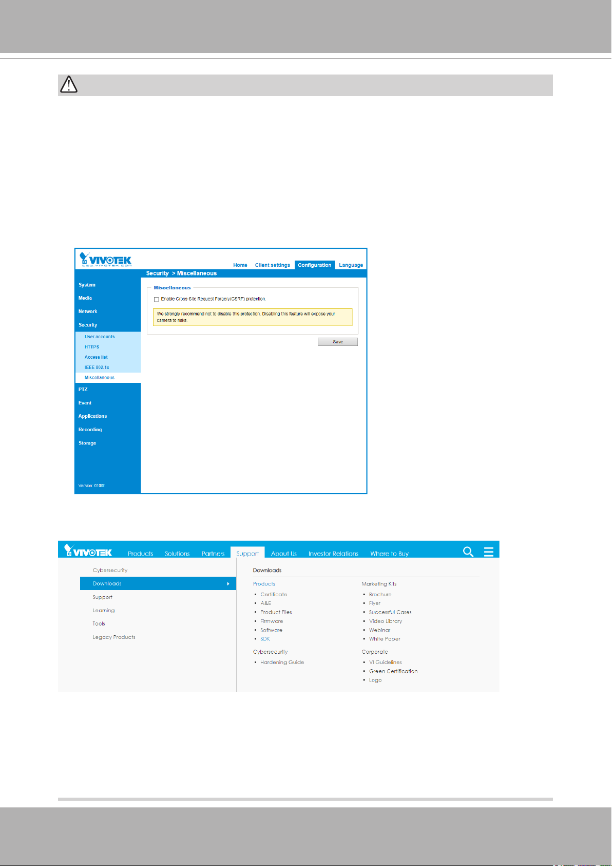
• To send URL commands in the address bar of your web browser, please remember to
disable the Cross-Site Request Forgery (CSRF) protection in Conguration > Security
> Miscellaneous.
• For up-to-date documentation of URL commands, please go to VIVOTEK’s website,
register an account with a business mail address and submit for authorization for SDK
in Support > Downloads > SDK.
• For any further technical support, please contact our technical support department.
6 - User's Manual
Page 7
i
Package Contents
■ FD9165 or FD9365
■ Desiccant bag (FD9365), screws, L wrench.
■ Quick Installation Guide.
■ Waterproof cable gland.
WARNING:
1. IR lights emit from ths product.
2. Use live view to verify if the IR lights are on in the night mode.
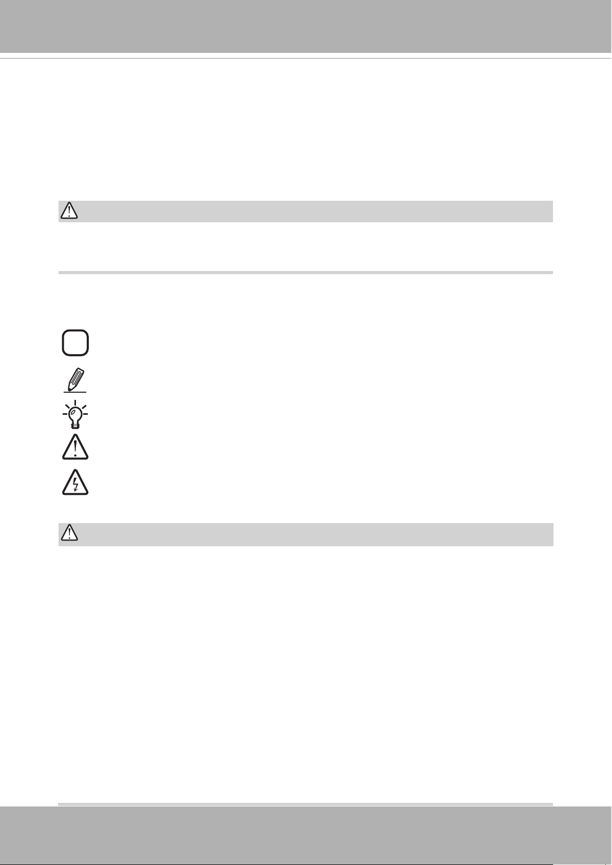
Symbols and Statements in this Document
VIVOTEK
INFORMATION:
inconvenient or problem situations.
NOTE
Tips
Electrical Hazard
: Notices provide guidance or advices that are related to the functional integrity of
the machine.
: Tips are useful information that helps enhance or facilitae an installation, function,
or process.
WARNING: or IMPORTANT:
dangerous or hazardous to the machine or you.
occur to an operator.
provides important messages or advices that might help prevent
: These statements indicate situations that can be
: This statement appears when high voltage electrical hazards might
IMPORTANT:
1. The camera is only to be connected to PoE networks without routing to outside plants.
2. For PoE connection, use only UL listed I.T.E. with PoE output.
1. La caméra ne doit être raccordée qu’à des réseaux PoE, sans routage vers des
installations extérieures.
2. Pour les raccordements PoE, utilisez uniquement un équipement de TI homologué UL,
avec une sortie PoE.
Use the camera only with a DC power supply that is UL listed, and limited power source
(LPS) certied. The power supply should bear the UL listed and LPS marks. The power
supply should also meet any safety and compliance requirements for the country of use.
n’utilisez la caméra qu’avec un bloc d’alimentation CC homologué UL, ainsi qu’avec
une alimentation limitée (LPS) certiée. Le bloc d’alimentation doit porter les indications
d'homologation UL et LPS. Il doit également répondre aux exigences en matière de
sécurité et de conformité relatives au pays d’utilisation.
User's Manual - 7
Page 8
VIVOTEK
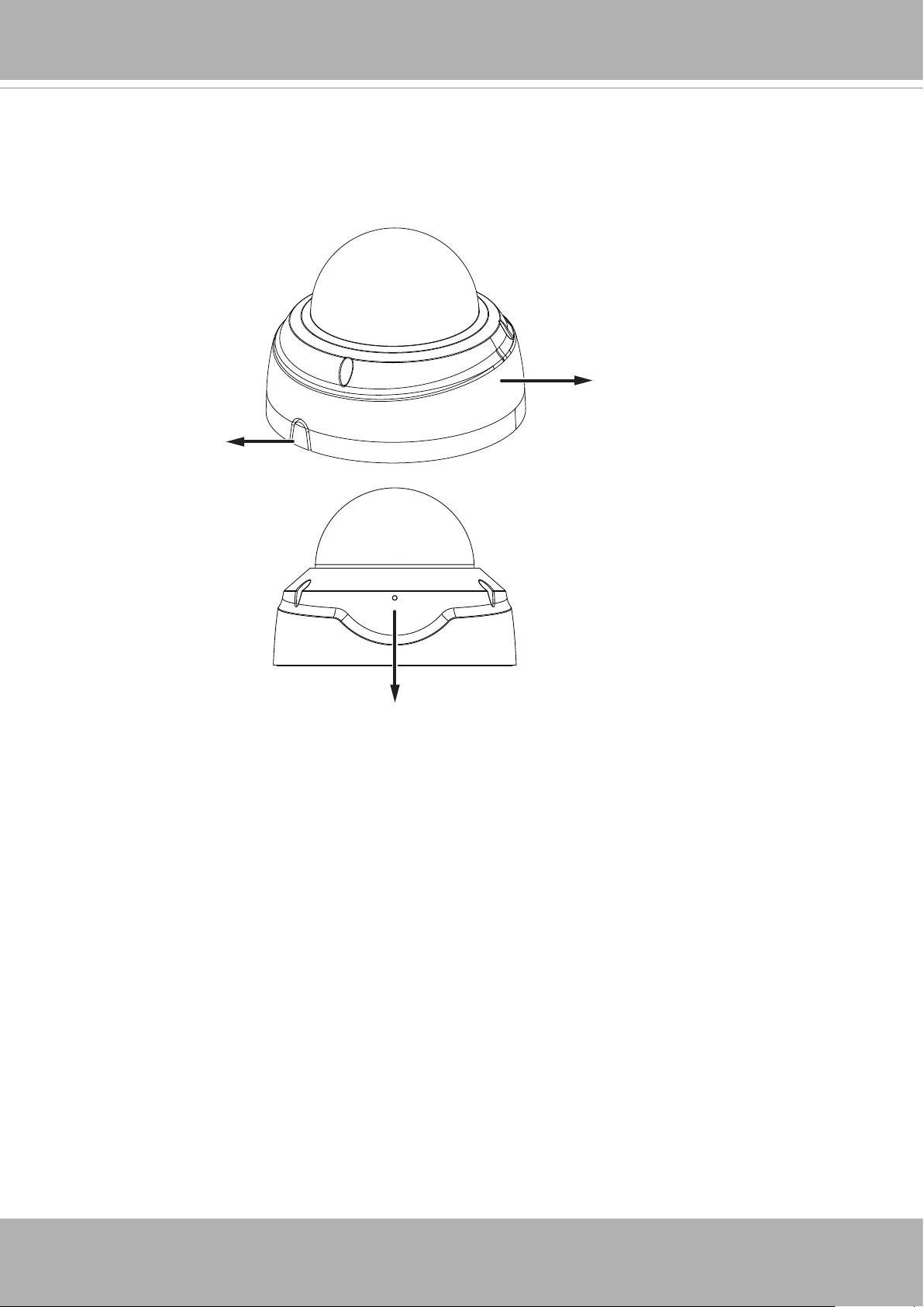
Physical Description
FD9165 Outer View
Routing hole
breakaway tab
Dome cover
Microphone
8 - User's Manual
Page 9
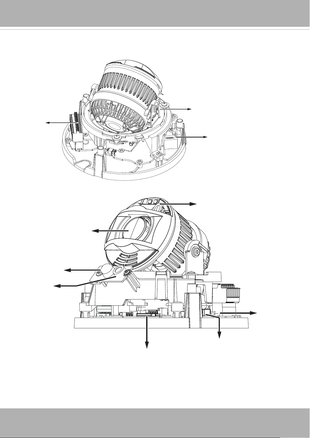
FD9165 Inner View
VIVOTEK
DI/DO terminal
block
Tilt retention screw
RJ45 Ethernet socket
IR LEDs
Lens
PIR
Microphone
Reset button
LEDs
MicroSD card slot
User's Manual - 9
Page 10
VIVOTEK
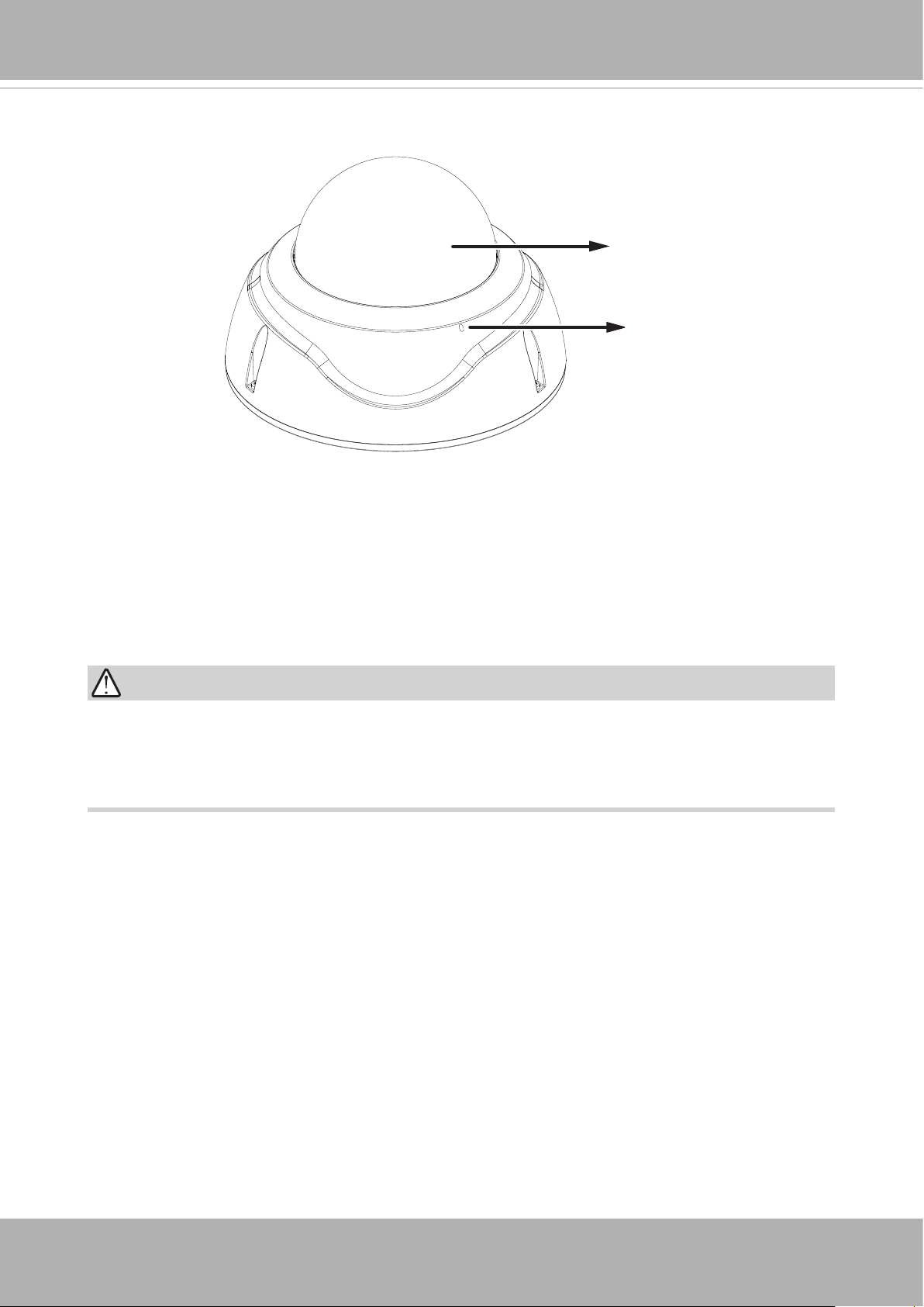
FD9365 Outer View
Dome cover
Microphone
IMPORTANT:
Many copper coated aluminum (CCA) and other non-standard conductors cabling products
are masqueraded as CAT5E or CAT6 cables. Please avoid using these CCA products
especially when cascading PoE cameras. It is a must to use Ethernet cables compliant
with the 3P/ETL standard.
10 - User's Manual
Page 11
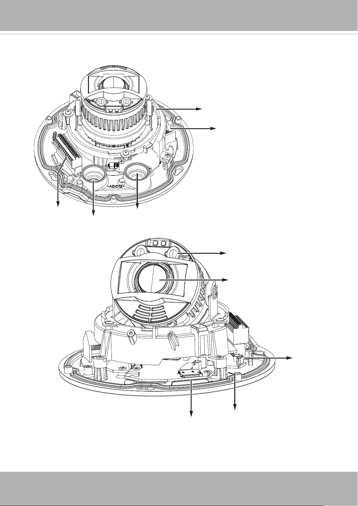
FD9365 Inner View
VIVOTEK
Tilt retention screw
RJ45 Ethernet socket
DI/DO terminal block
Cable gland hole for
Ethernet
Cable gland hole for DI/DO
IR LEDs
Lens
Reset button
MicroSD card slot
LEDs
User's Manual - 11
Page 12
VIVOTEK
NOTE:
Some of the sufx syntax used in model naming are listed below:
E w/ heater for extreme weather
Fx Focal length w/ number
T w/ Remote focus lens
R w/ PoE repeater
H w/ High Dynamic Range functionality
M Manual focus lens
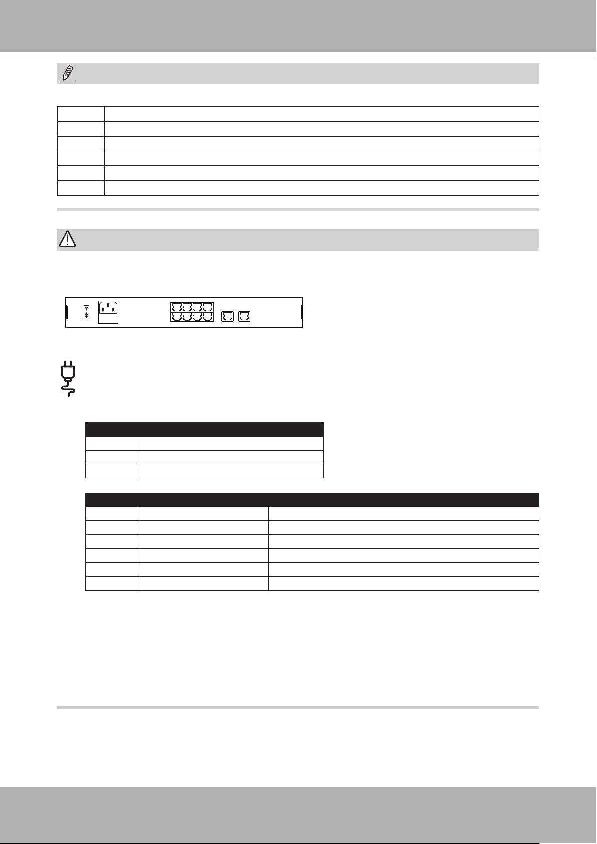
IMPORTANT:
802.3af or 802.3at
3
ON
OFF
100~240V
AC
7
LAN/PoE
1
658
4
2
9
GE LAN GE LAN
10
The E model camera comes with an embedded heater and requires an 802.3at PoE
switch.
Source Consumption & Power Input
PoE 11W [42.5V(0.26) ~ 57V(0.19)]
DC 12V 8W (0.67A)
AC 24V 9.5W (0.72A; PF0.55)
Source Operating Temperature Consumption & Power Input
PoE Heater ON 21W [42.5V(0.5)-57V(0.37)]
Heater OFF 11W
DC 12V Heater ON 18W (1.5A)
Heater OFF 8W (0.67A)
AC 24V Heater ON 19.5W (1.48A; PF0.55)
Heater OFF 9.5W (0.72A; PF0.55)
* FD9365-HTV-A has no heater.
12 - User's Manual
Page 13
VIVOTEK
Hardware Installation (FD9165)
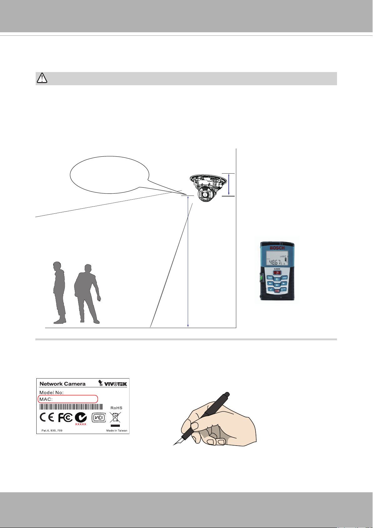
IMPORTANT:
If you plan to use the Human Detection feature, make sure you measure the installation
height of your camera. The height information is important for the accuracy of the video
analytics results. Some of the other perspective information are automatically collected by
the onboard S-sensor. The height information enables the horizontal and vertical keystone
corrections of the eld of view. Measure the distance between camera lens and the
ground.
Measured to the
approx. lens position.
Not to the ceiling.
Installation
height
1. Jot down the camera's MAC address for later reference.
XXXXXX
0002D10766AD
User's Manual - 13
Page 14
VIVOTEK
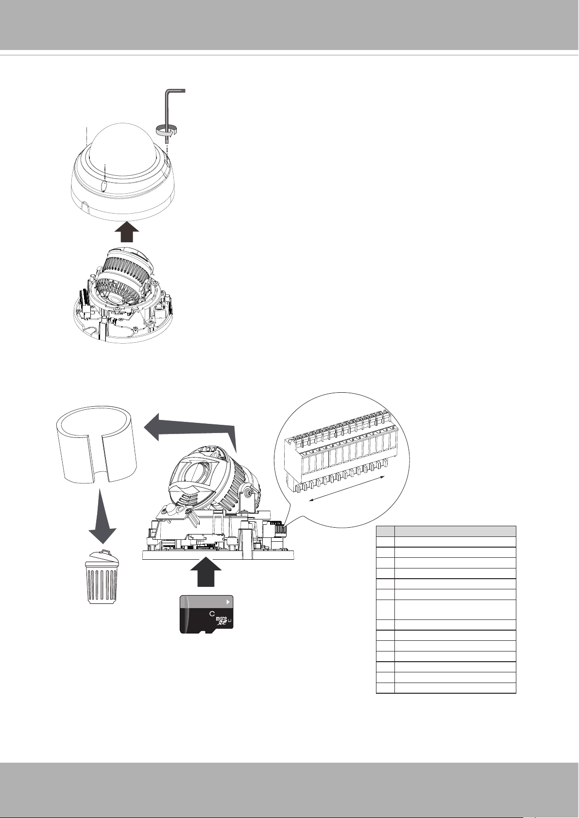
2. Remove the dome cover by loosening 4 T10 screws.
3. Install an MicroSD card if onboard storage is preferred. Remove the foam pad around
the lens module.
1
14
# Name
1 AC24V
2 AC24V
3 DC12V IN4 DC12V IN+
5 VIDEO OUT N
6 VIDEO OUT P
64
GB
10
1
I
7 DI- (GND, also a common GND
for DO, MIC IN, & AUDIO OUT)
8 DI1+
9 DI0+
10 DO111 DO012 DO+ (12V)
13 MIC IN P
14 AUDIO OUT P
14 - User's Manual
Page 15
VIVOTEK
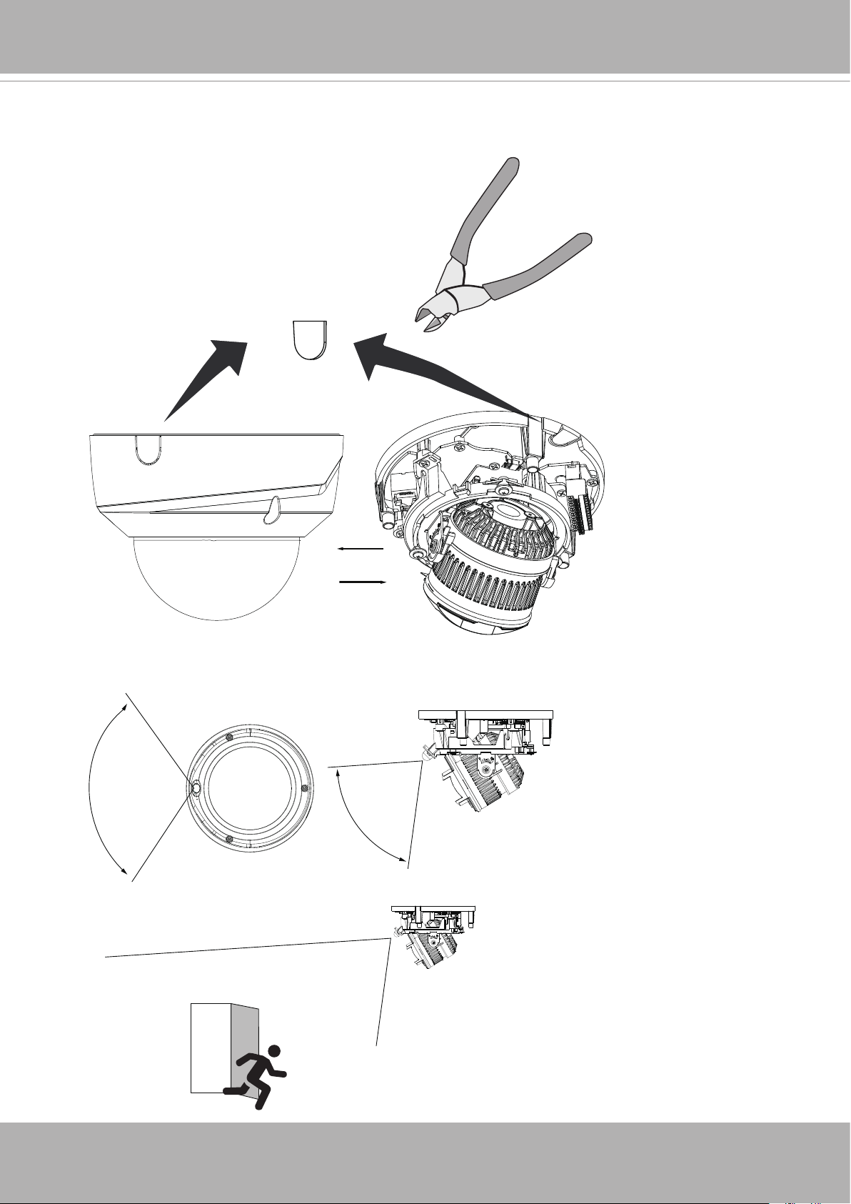
4. Remove the breakaway tab at the bottom or on the side of the dome cover depending
on how you route your Ethernet cable.
OR
5. Note the PIR detection range when choosing an installation position.
PIR
PIR
121°
5M
77.3°
5M
User's Manual - 15
Page 16
VIVOTEK
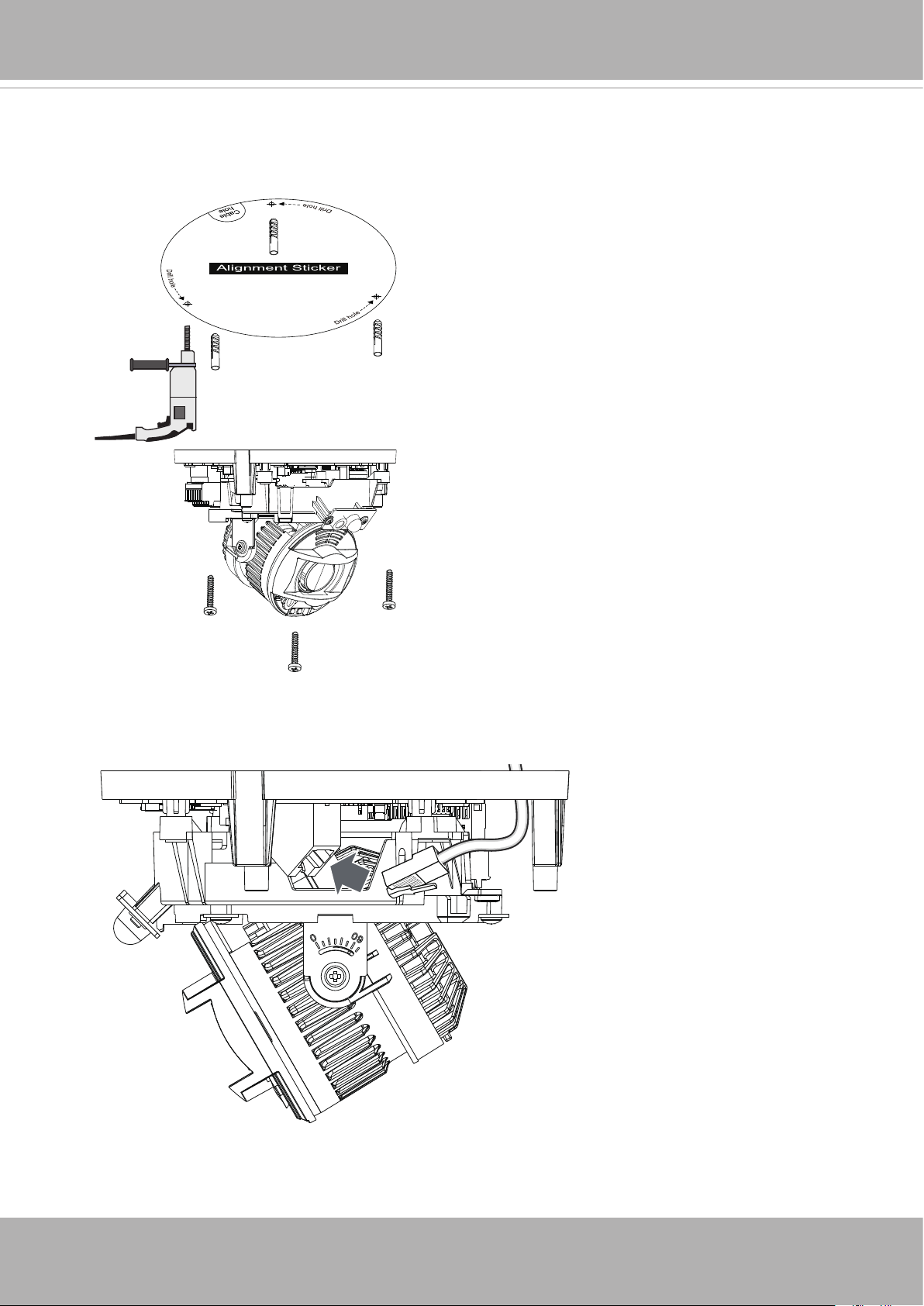
6. Drill holes for mounting screws and a cabling hole if applicable. Pull a CAT5e Ethernet
cable through the hole. Secure the camera to wall or ceiling using the included screws.
7. Connect the Ethernet cable to the RJ45 port.
16 - User's Manual
Page 17
VIVOTEK
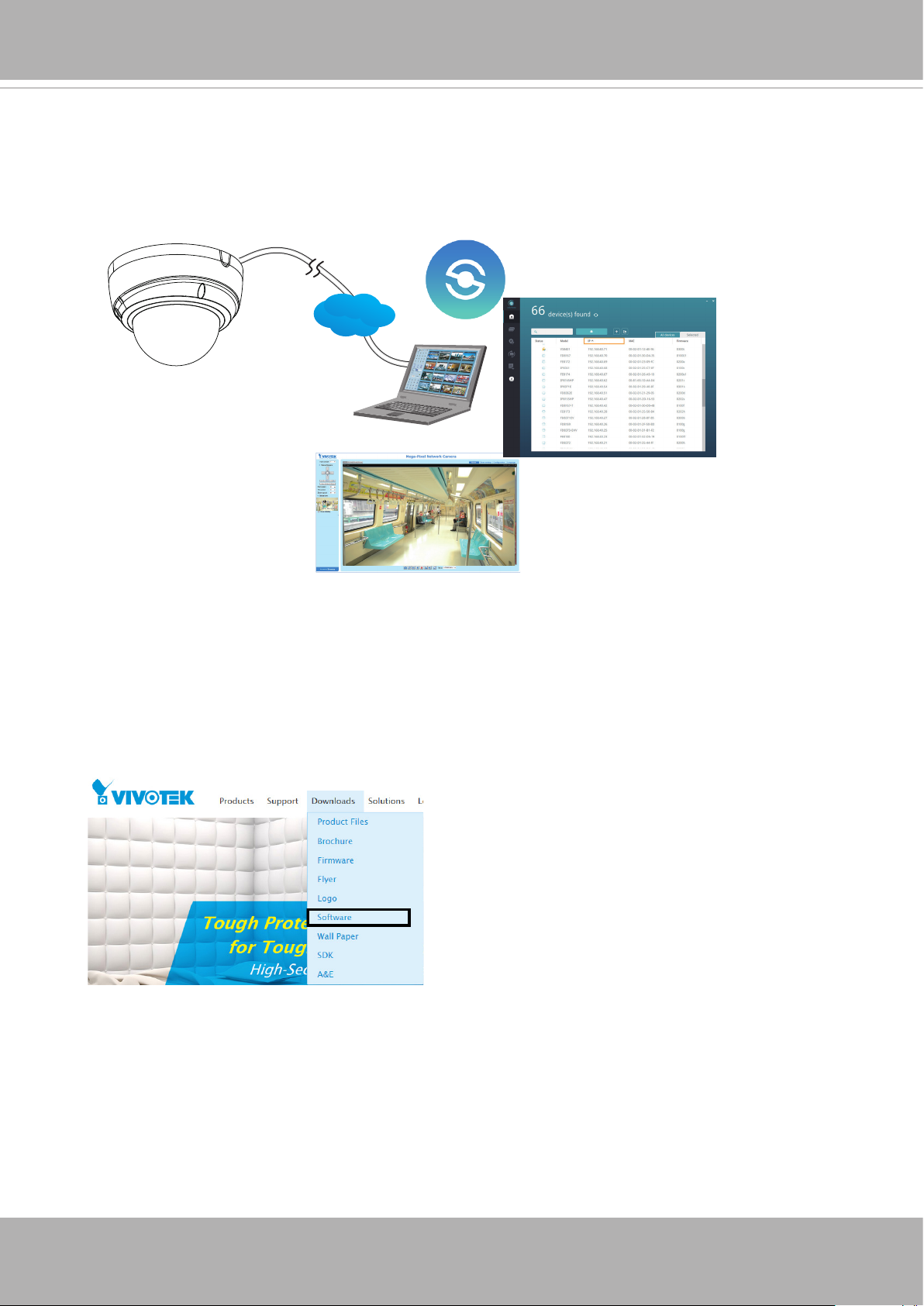
8. Please visit VIVOTEK’s website to Install the "Shepherd” software utility. The program
will search for VIVOTEK Video Receivers, Video Servers or Network Cameras on the
same LAN.
Double-click on the camera’s MAC address to open a web console with the camera.
Shepherd
LAN
Browser
Software Installation
9. Install the
in the local network. If your camera comes without the CD, go to VIVOTEK’s website,
and locate the utility in the Downloads > Software page.
Shepherd
utility, which helps you locate and congure your Network Camera
User's Manual - 17
Page 18
VIVOTEK
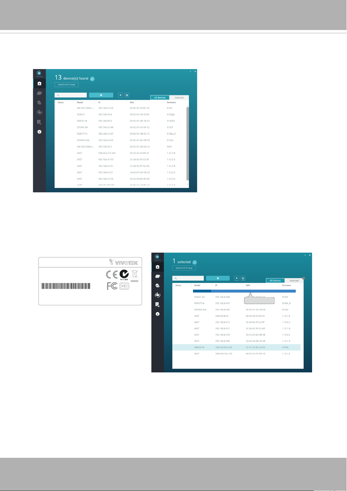
9-1. Run the Shepherd utility.
9-2. The program will conduct an analysis of your network environment.
9-3. The program will search for all VIVOTEK network devices on the same LAN.
9-4. After a brief search, the installer window will prompt. Click on the MAC and model
name that matches the one printed on the product label. You can then double-click on
the address to open a management session with the Network Camera.
Network Camera
Model No: xxxxxxx
MAC:0002D1730202
This device complies with part 15 of the FCC rules. Operation is subject to the following two conditions:
(1)This device may not cause harmful interference, and
(2) this device must accept any interference received, including interference that may cause undesired operation.
Pat. 6,930,709
R o HS
Made in Taiwan
FD9165-HT-A
IB8360-W 192.168.4.151 00-02-D1-73-02-02
0002D1730202
18 - User's Manual
Page 19
VIVOTEK
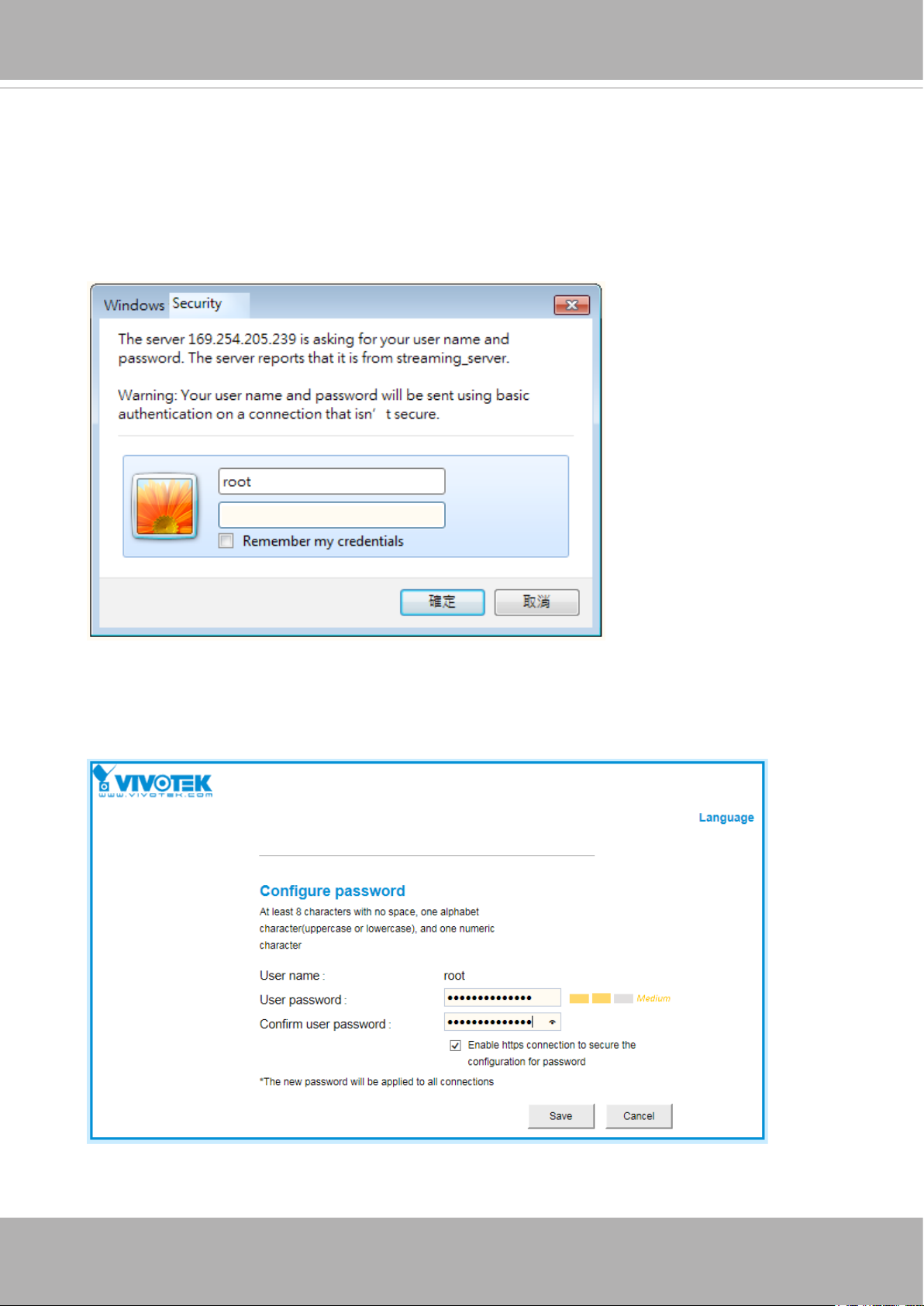
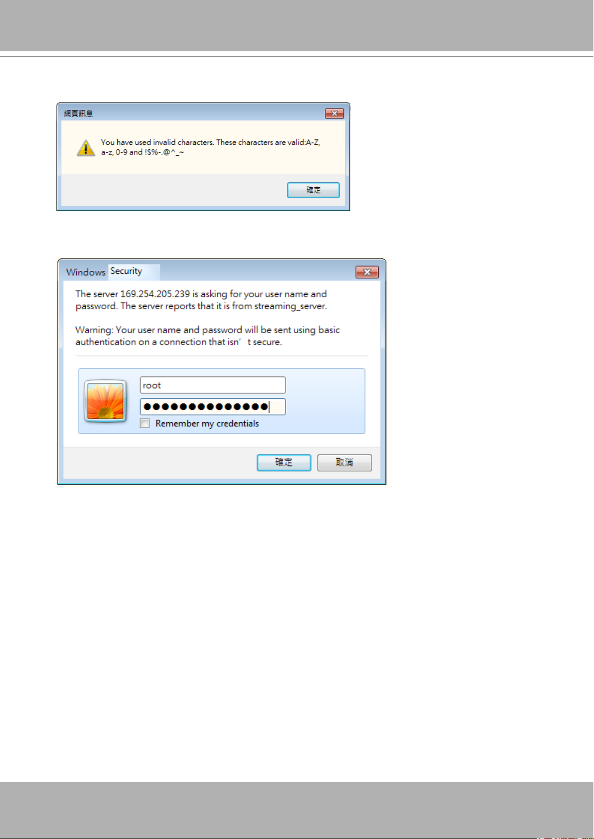
Forceful Password Conguration
10. The first time you log in to the camera, the firmware will prompt for a password
conguration for security concerns.
10-1. Since your camera is used for the rst time, there is no password. Enter “root” as the
user name, and nothting for the password.
10-2. Enter the combination of alphabetic and numeric characters to fulll the password
strength. requirement. The default name for the camera administrator is “root”, and can
not be changed.
User's Manual - 19
Page 20
VIVOTEK
Some, but not all special ASCII characters are supported: !, $, %, -, ., @, ^, _, and ~.
You can use them in the password combination.
10-3. Another prompt will request for the password you just congured. Enter the password
and then you can start congure your camera and see the live view.
20 - User's Manual
Page 21
VIVOTEK
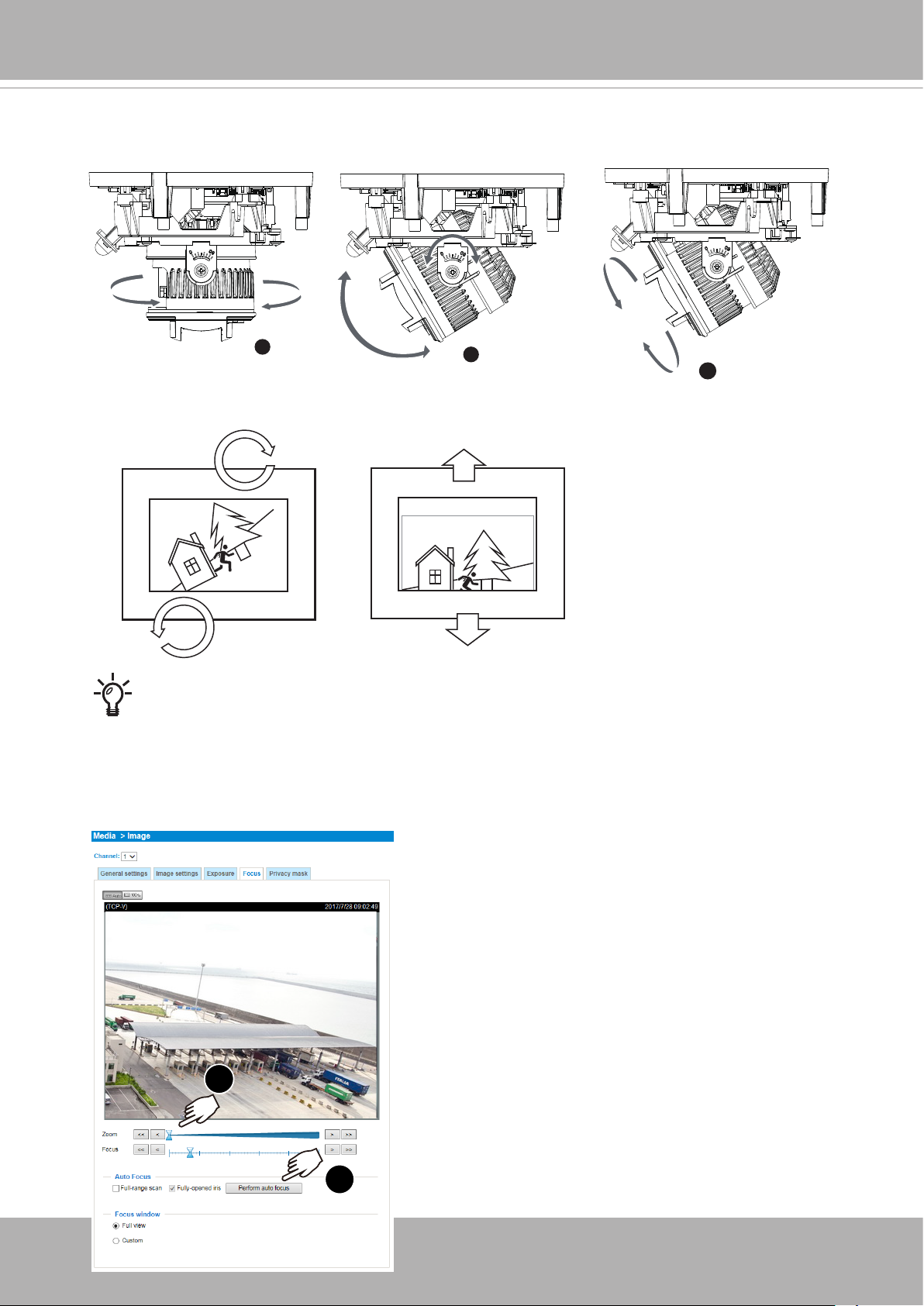
11. Loosen, but not completely remove, the retention screws on lens module bracket to
adjust the camera’s shooting direction. You can pan, tilt, or rotate the camera lens.
350°
1
60°
2
3
±175°
For the -HT and -EHT models, open a web console. From a web console, open
the firmware configuration page. Enter the Configuration > Media > Image > Focus page. You will see a live stream on screen. If preferred, you can zoom in on
the scene. Use the “Perform Auto Focus” function to automatically tune to a best
image focus. Check the live view to ensure the image is in focus.
Conguration > Media > Image > Focus
1
2
User's Manual - 21
Page 22
VIVOTEK
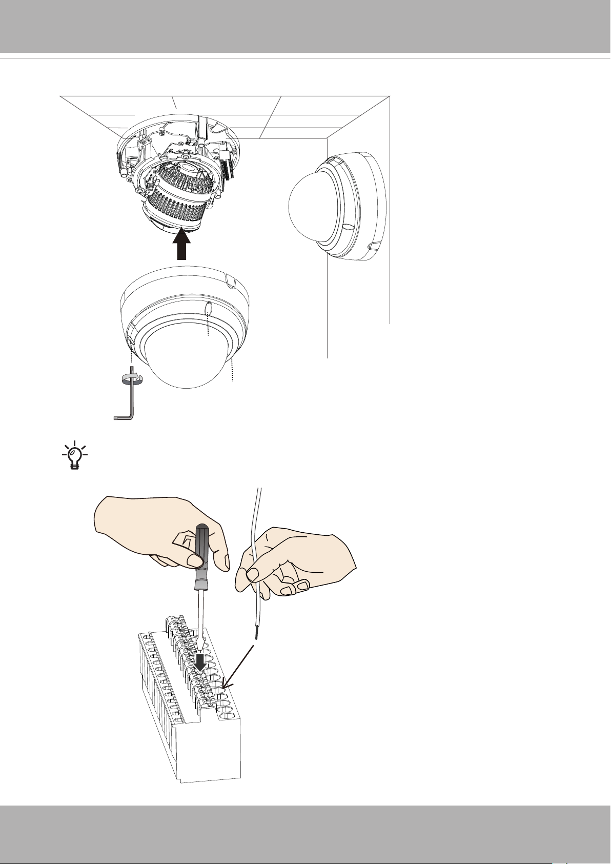
12. Install the dome cover. Remove the protective sheet from the dome cover.
Use a small flat-blade screwdriver to press down the small tabs on the terminal
block to secure the DI/DO wires.
22 - User's Manual
Page 23
Hardware Installation (FD9365)
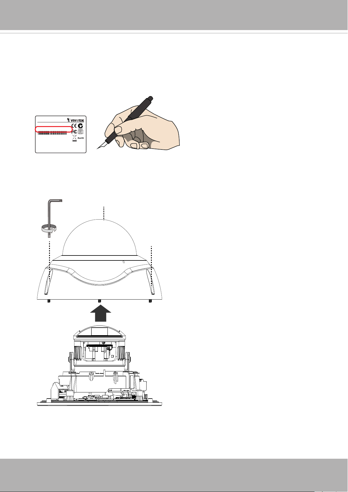
1. Jot down the camera's MAC address for later reference.
MAC
Network Camera
Model No: XXXXXX
MAC: 0002D1083236
This device complies with part 15 of the FCC Rules. Operation is subject to
the following two conditions:
(1) this device may not cause harmful interference, and
(2) this device must accept any interference received, including interference
that may cause undesired operation.
Pat. 6,930,709
2. Remove the dome cover using the included T10 L wrench.
Made in Taiwan
VIVOTEK
T10
User's Manual - 23
Page 24
VIVOTEK
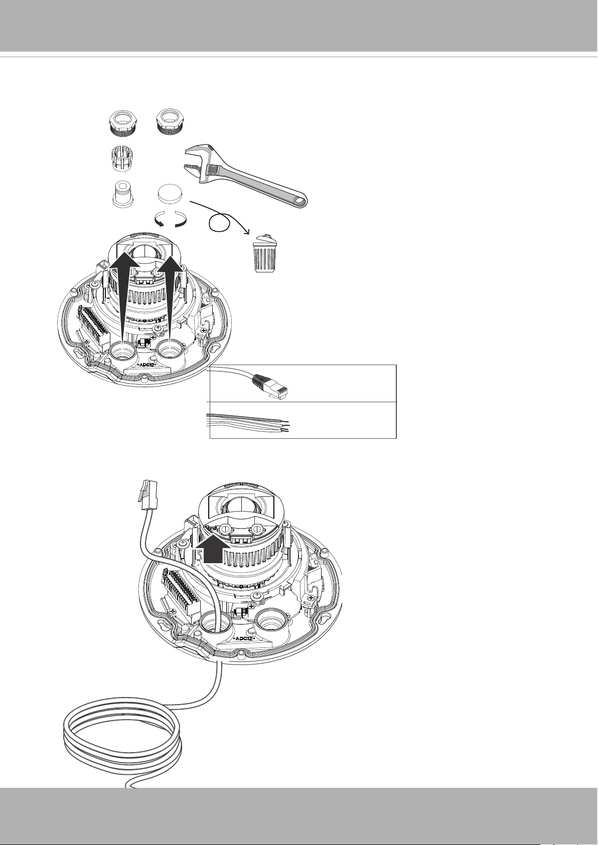
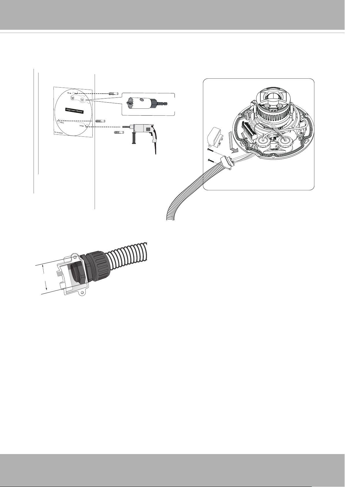
3. Remove the hex nuts and cable gland components. On the DI/DO cable gland hole,
there is a plastic plug. Remove it and install the DI/DO cable gland.
5 ~ 6.3mm
DI/DO: 1.8 ~ 2.1mm
4. Pass an Ethernet cable through the routing hole.
24 - User's Manual
Page 25
VIVOTEK
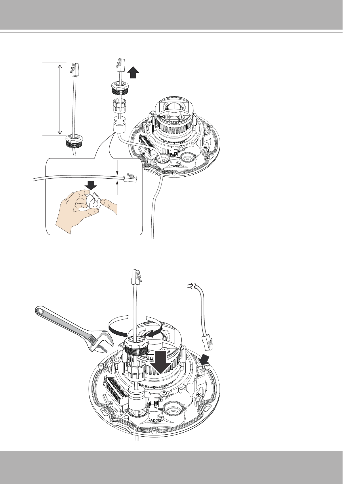
5. Install the components of the waterproof cable gland to the cable. Leave 18cm of cable
length inside the canister.
approx.
18cm
Ø 5 ~ 6.3mm
6. Use a crescent wrench to tighten the components of the cable gland. Connect the
Ethernet connector to the RJ45 socket.
User's Manual - 25
Page 26
VIVOTEK
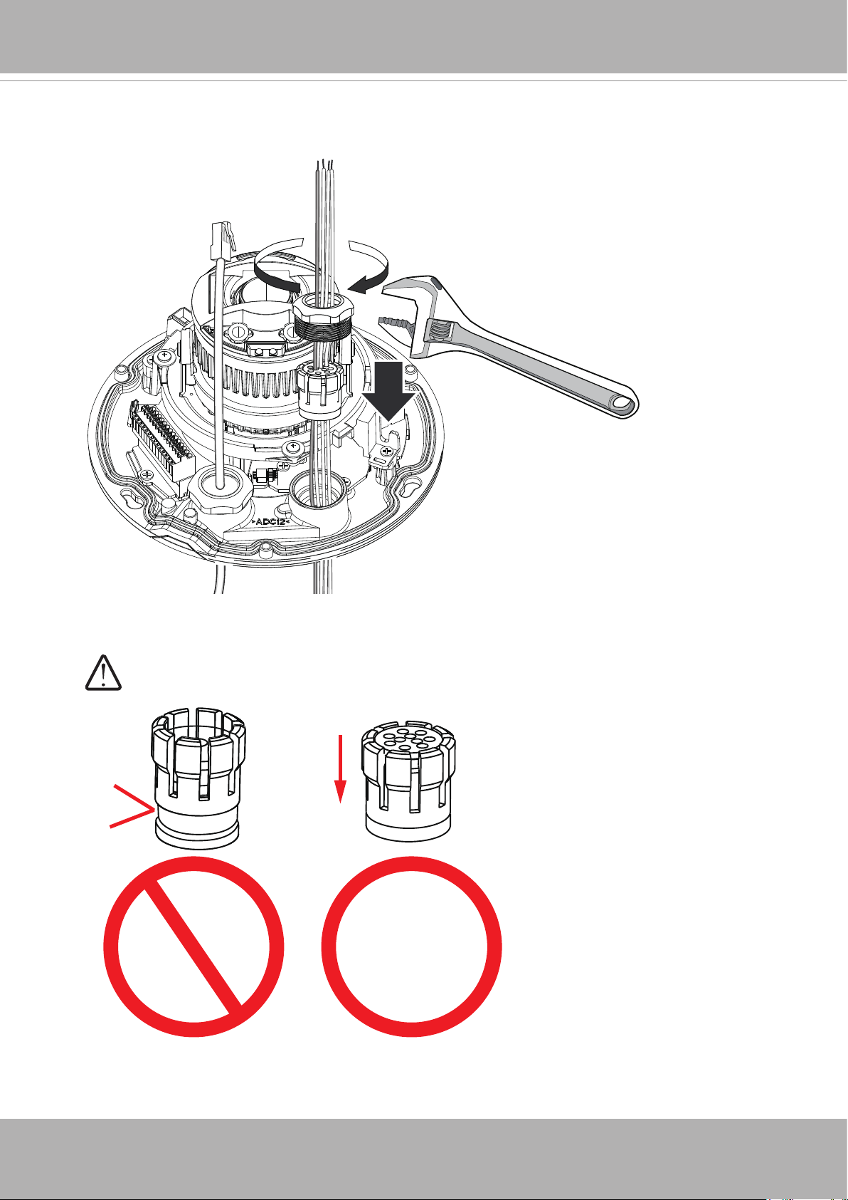
7. If you need to connect sensors or external devices via the DI/DO cable gland, pass them
through the rubber seal and tighten the components of cable gland.
Make sure the clamping claw and rubber seal are properly installed.
26 - User's Manual
Page 27
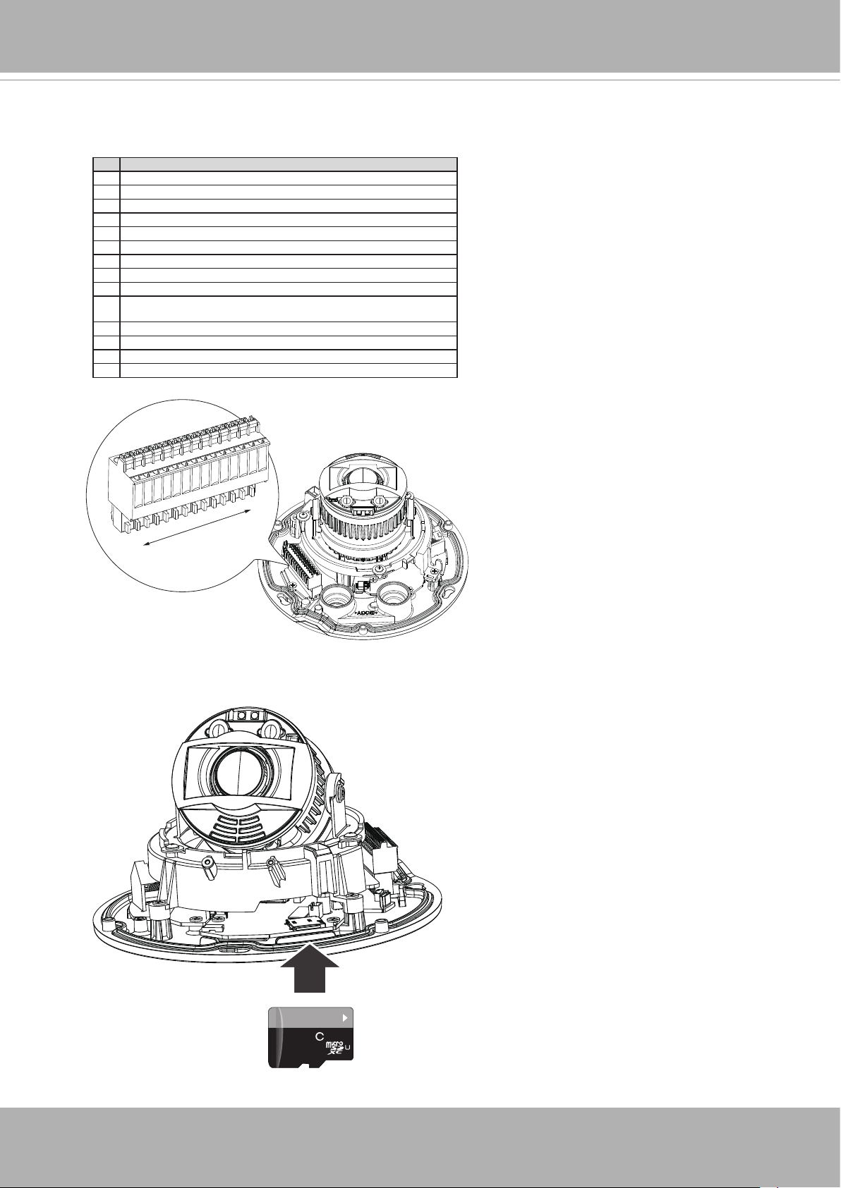
8. Shown below is the pinouts of the terminal block. Note that if AC 24V power source
is preferred, an additional power board is required. Please contact your sales
representative for the requirement.
# Name
1 AC 24V
2 AC 24V
3 DC 12V IN4 DC 12V IN+
5 VIDEO-OUT N
6 VIDEO-OUT P
7 DI- (Common GND for all DI, DO, MIC-IN, and AUDIO-OUT)
8 DI+ 1
9 DI+ 0
10 DO- 1 (If external devices are powered by external sources, can use DI- as
common ground)
11 DO- 0
12 DO+ (12V; if used, can be paired with DO- 0 and DO- 1.)
13 MIC-IN P
14 AUDIO-OUT P
VIVOTEK
1
14
9. Install an SD card if onboard storage is preferred.
64
GB
10
1
I
User's Manual - 27
Page 28
VIVOTEK
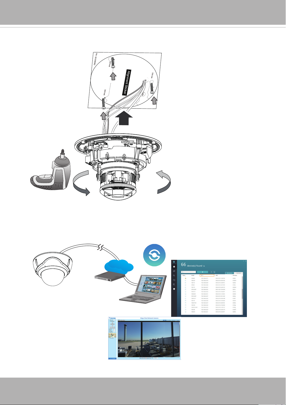
10. Drill holes on the wall or ceiling for installation and routing the cables. You can also
route cables through the side of the camera using the included bushing. You can install
a 3/4" conduit for cable protection. Note that the hex nut of the conduit connector should
not be larger than 35mm.
- OR -
Ø< 35mm
3/4"
≤3/4”
28 - User's Manual
Page 29
VIVOTEK
11. Install the camera by aligning the key slot holes with the screws and turning the camera
counter-clockwise. Tighten the screws to secure the camera.
12. Please visit VIVOTEK’s website to Install the "Shepherd” software utility. The program
will search for VIVOTEK Video Receivers, Video Servers or Network Cameras on the
same LAN.
Double-click on the camera’s MAC address to open a web console with the camera.
Shepherd
LAN
Browser
User's Manual - 29
Page 30
VIVOTEK
Software Installation
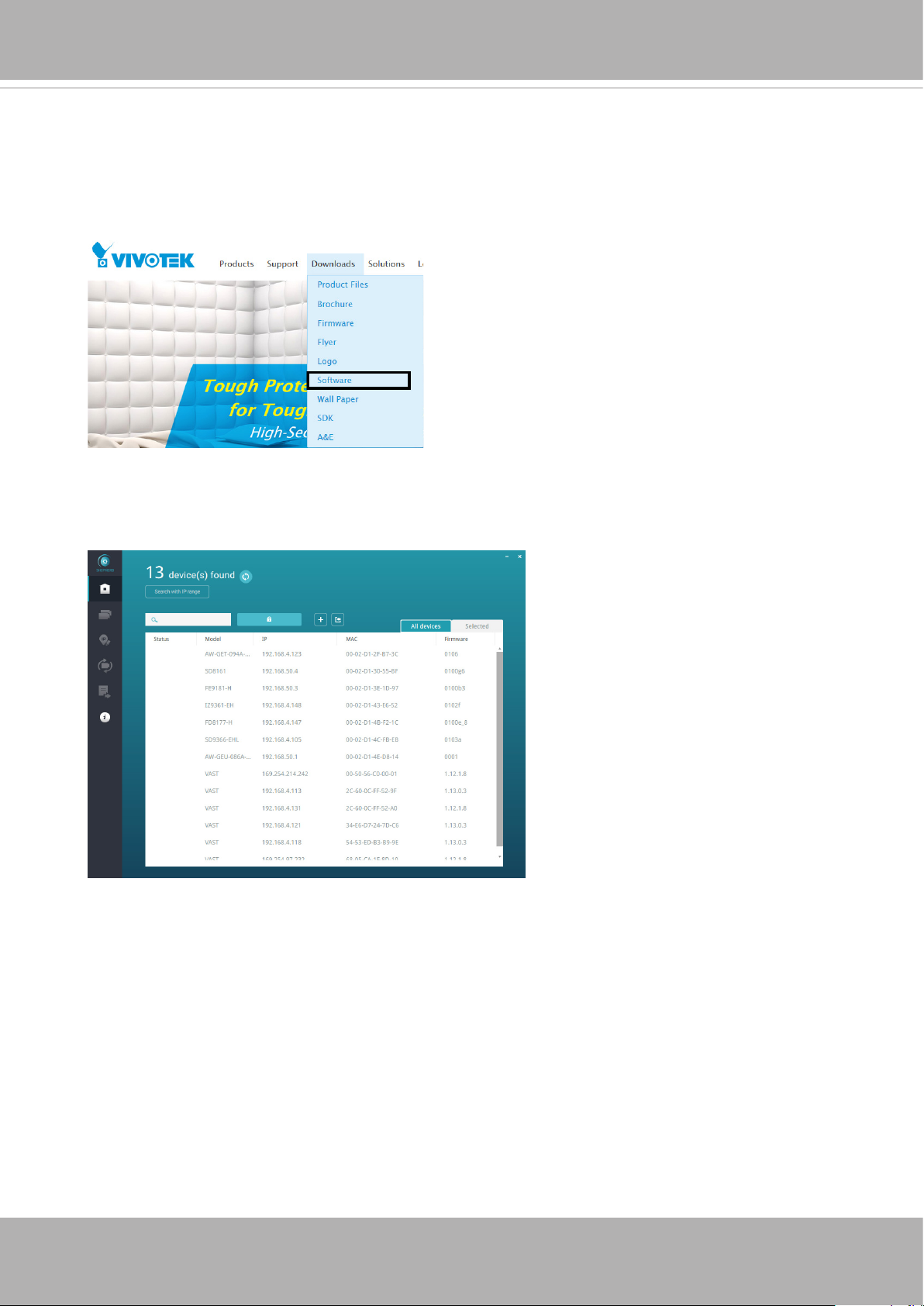
13. Install the
Shepherd
utility, which helps you locate and congure your Network Camera
in the local network. If your camera comes without the CD, go to VIVOTEK’s website,
and locate the utility in the Downloads > Software page.
13-1. Run the Shepherd utility.
13-2. The program will conduct an analysis of your network environment.
30 - User's Manual
Page 31

VIVOTEK
13-3. The program will search for all VIVOTEK network devices on the same LAN.
13-4. After a brief search, the installer window will prompt. Click on the MAC and model
name that matches the one printed on the product label. You can then double-click on
the address to open a management session with the Network Camera.
Network Camera
Model No: xxxxxxx
MAC:0002D1730202
This device complies with part 15 of the FCC rules. Operation is subject to the following two conditions:
(1)This device may not cause harmful interference, and
(2) this device must accept any interference received, including interference that may cause undesired operation.
Pat. 6,930,709
R o HS
Made in Taiwan
FD9165-HT-A
IB8360-W 192.168.4.151 00-02-D1-73-02-02
0002D1730202
User's Manual - 31
Page 32

VIVOTEK
Forceful Password Conguration
14. The first time you log in to the camera, the firmware will prompt for a password
conguration for security concerns.
14-1. Since your camera is used for the rst time, there is no password. Enter “root” as the
user name, and nothting for the password.
14-2. Enter the combination of alphabetic and numeric characters to fulll the password
strength. requirement. The default name for the camera administrator is “root”, and can
not be changed.
32 - User's Manual
Page 33

VIVOTEK
Some, but not all special ASCII characters are supported: !, $, %, -, ., @, ^, _, and ~.
You can use them in the password combination.
14-3. Another prompt will request for the password you just congured. Enter the password
and then you can start congure your camera and see the live view.
User's Manual - 33
Page 34

VIVOTEK
15. With a live view displayed on your laptop, adjust the zoom and focus to obtain an
optimal image. Check the live view to ensure the image is in focus.
The "T" models comes with motorized focus lens. Use the Auto Focus function in
rmware menu for best image.
When panning the lens, you do not need to loosen the retention screws. You need to
loosen the screws when tilting the lens.
350°
0°~ 60°
34 - User's Manual
Page 35

VIVOTEK
Conguration > Media > Image > Focus
For the -HT, -HTV, and -EHTV models, open a web console. From a web console, open
the firmware configuration page. Enter the Configuration > Media > Image > Focus page.
You will see a live stream on screen. If preferred, you can zoom in on the scene. Use the
“Perform Auto Focus” function to automatically tune to a best image focus. Check the live
view to ensure the image is in focus.
1
2
16. Tighten the tilt retention screws.
User's Manual - 35
Page 36

VIVOTEK
17. Replace the desiccant bags on the dome cover. Whenever you open the dome cover,
you should replace the desiccants.
1
18. Install the dome cover. Remove the protective sheet from the dome cover.
2
36 - User's Manual
Page 37

LED Denitions
Item LED status Description
LED Denition
1 Steady Red Powered and system booting, or network
failed
Red LED off Power off
Green LED off Network is disconnected
2 Steady Red and Green LED blinks every 1
sec.
3 Green LED blinks every 1 sec. and RED
LED blinks consecutively every 0.15 sec.
4 Green and RED blink every 0.15 sec, Green
and RED light on, then blink again.
Connected to network
Upgrading rmware
Restoring defaults
VIVOTEK
5 RED LED is on, Green LED blinks and RED
LED is constantly on.
Green and RED LEDs are constantly on. Status after a reset (network
Status after a reset (network connected)
disconnected)
Hardware Reset
The reset button is used to reset the system or restore the factory default settings.
Sometimes resetting the system can return the camera to normal operation. If the system
problems remain after reset, restore the factory settings and install again.
Reset: Press the recessed reset button. Wait for the Network Camera to reboot.
Restore: Press and hold the reset button until the status LED rapidly blinks. Note that all
settings will be restored to factory default. Upon successful restore, the status LED will
blink green and red during normal operation.
SD/SDHC/SDXC Card Capacity
This network camera is compliant with
other preceding standard SD cards.
SD/SDHC/SDXC 16GB / 8GB / 32GB / 64GB
and
User's Manual - 37
Page 38

VIVOTEK
Network Deployment
General Connection (PoE)
When using a PoE-enabled switch
The Network Camera is PoE-compliant, allowing transmission of power and data via a single Ethernet cable. Follow the below illustration to connect the Network Camera to a PoEenabled switch via Ethernet cable.
802.3af
PoE Switch
802.3at for -EHTV
When using a non-PoE switch
Use a PoE power injector (optional) to connect between the Network Camera and a nonPoE switch.
PoE Power Injector
(optional)
802.3at for -EHTV
38 - User's Manual
Non-PoE Switch
Page 39

Ready to Use
1. A browser session with the Network Camera should prompt as shown below.
2. You should be able to see live video from your camera. You may also install the
32-channel recording software from VIVOTEK's website in a deployment consisting of
multiple cameras. For its installation details, please refer to its related documents.
VIVOTEK
IMPORTANT:
The "E" models, e.g., FD9365-EHTV-A, are able to operate in low temperature
•
environments. However, when starting these cameras in a very low termperature
condition, e.g., -40ºC, the embedded heater may take half an hour to warm up
the camera. When the temperature within the canister reaches -10ºC, the camera
automatically starts.
User's Manual - 39
Page 40

VIVOTEK
Internet connection via a router
Before setting up the Network Camera over the Internet, make sure you have a router and follow
the steps below.
1. Connect your Network Camera behind a router, the Internet environment is illustrated below.
Regarding how to obtain your IP address, please refer to Software Installation on page 20 for
details.
IP address : 192.168.0.3
Subnet mask : 255.255.255.0
Default router : 192.168.0.1
IP address : 192.168.0.2
Subnet mask : 255.255.255.0
Default router : 192.168.0.1
Internet
Cable or DSL Modem
WAN (Wide Area Network )
Router IP address : from ISP
LINK
POWER
COLLISION
RECEIVE
1
2
PARTITION
3
4
5
LAN (Local Area Network)
Router IP address : 192.168.0.1
2. In this case, if the Local Area Network (LAN) IP address of your Network Camera is
192.168.0.3, please forward the following ports for the Network Camera on the router.
■ HTTP port: default is 80
■ RTSP port: default is 554
■ RTP port for video: default is 5556
■ RTCP port for video: default is 5557
If you have changed the port numbers on the Network page, please open the ports
accordingly on your router. For information on how to forward ports on the router, please refer
to your router’s user’s manual.
3. Find out the public IP address of your router provided by your ISP (Internet Service Provider).
Use the public IP and the secondary HTTP port to access the Network Camera from the
Internet. Please refer to Network Type on page 100 for details.
Internet connection with static IP
Choose this connection type if you are required to use a static IP for the Network Camera.
Please refer to LAN setting on page 99 for details.
Internet connection via PPPoE (Point-to-Point over Ethernet)
Choose this connection type if you are connected to the Internet via a DSL Line. Please refer to
PPPoE on page 100 for details.
40 - User's Manual
Page 41

VIVOTEK
For example, your router and IP settings may look like this:
Device IP Address: internal port IP Address: External Port (Mapped
port on the router)
Public IP of router 122.146.57.120
LAN IP of router 192.168.2.1
Camera 1 192.168.2.10:80 122.146.57.120:8000
Camera 2 192.168.2.11:80 122.146.57.120:8001
... ... ...
Congure the router, virtual server or rewall, so that the router can forward any data coming into a precongured port number to a network camera on the private network, and
allow data from the camera to be transmitted to the outside of the network over the same
path.
From Forward to
122.146.57.120:8000 192.168.2.10:80
122.146.57.120:8001 192.168.2.11:80
... ...
When properly congured, you can access a camera behind the router using the HTTP
request as follows: http://122.146.57.120:8000
If you change the port numbers on the Network conguration page, please open the ports
accordingly on your router. For example, you can open a management session with your
router to congure access through the router to the camera within your local network.
Please consult your network administrator for router conguration if you have troubles with
the conguration.
For more information with network conguration options (such as that of streaming ports),
please refer to Conguration > Network Settings. VIVOTEK also provides the automatic
port forwarding feature as an NAT traversal function with the precondition that your router
must support the UPnP port forwarding feature.
User's Manual - 41
Page 42

VIVOTEK
Accessing the Network Camera
This chapter explains how to access the Network Camera through web browsers, RTSP players,
3GPP-compatible mobile devices, and VIVOTEK recording software.
Using Web Browsers
Use Installation Wizard 2 (IW2) to access the Network Cameras on LAN.
If your network environment is not a LAN, follow these steps to access the Netwotk Camera:
1. Launch your web browser (e.g., Microsoft® Internet Explorer or Mozilla Firefox).
2. Enter the IP address of the Network Camera in the address eld. Press
3. Live video will be displayed in your web browser.
4. If it is the rst time installing the VIVOTEK network camera, an information bar will prompt as
shown below. Follow the instructions to install the required plug-in on your computer.
Enter
.
NOTE:
NOTE
► For Mozilla Firefox or Chrome users, your browser will use QuickTime to stream the live
video. If you don’t have QuickTime on your computer, please download it rst, then launch
the web browser.
42 - User's Manual
Page 43

VIVOTEK
► By default, the Network Camera is not password-protected. To prevent unauthorized access,
it is highly recommended to set a password for the Network Camera.
For more information about how to enable password protection, please refer to Security on
page 119.
► If you see a dialog box indicating that your security settings prohibit running ActiveX®
Controls, please enable the ActiveX® Controls for your browser.
1. Choose Tools > Internet Options > Security > Custom Level.
2. Look for Download signed ActiveX® controls; select Enable or Prompt. Click OK.
3. Refresh your web browser, then install the ActiveX® control. Follow the instructions to
complete installation.
User's Manual - 43
Page 44

VIVOTEK
IMPORTANT:
Currently the Network Camera utilizes a 32-bit ActiveX plugin. You CAN NOT open a
•
management/view session with the camera using a 64-bit IE browser.
If you encounter this problem, try execute the Iexplore.exe program from C:\Windows\
•
SysWOW64. A 32-bit version of IE browser will be installed.
On Windows 7, the 32-bit explorer browser can be accessed from here:
•
C:\Program Files (x86)\Internet Explorer\iexplore.exe
If you open a web session from the Shepherd utility, a 32-bit IE browser will be
•
opened.
Tips:
1. The onscreen Java control can malfunction under the following situations: A PC connects to different cameras that are using the same IP address (or the same camera
running different rmware versions). Removing your browser cookies will solve this
problem.
2. If you encounter problems with displaying the conguration menus or UI items, try disable the Compatibility View on IE8 or IE9.
You may also press the F12 key to open the developer tools utility, and then change the
Browser Mode to the genuine IE8 or IE9 mode.
• In the event of plug-in compatibility issues, you may try to uninstall the plug-in that was
previously installed.
44 - User's Manual
Page 45

VIVOTEK
Using RTSP Players
To view the streaming media using RTSP players, you can use one of the following players that
support RTSP streaming.
Quick Time Player
VLC media player
VLC media player
1. Launch the RTSP player.
mpegable Player
2. Choose File > Open URL. A URL dialog box will pop up.
3. The address format is rtsp://<ip address>:<rtsp port>/<RTSP streaming access name for
pvPlayer
stream1 or stream2>
As most ISPs and players only allow RTSP streaming through port number 554, please set the
RTSP port to 554. For more information, please refer to RTSP Streaming on page 107.
For example:
rtsp://192.168.5.151:554/live1s1.sdp
4. The live video will be displayed in your player.
For more information on how to configure the RTSP access name, please refer to RTSP
Streaming on page 107 for details.
Video 16:38:01 2012/01/25
User's Manual - 45
Page 46

VIVOTEK
Video quality (Constant bit rate) 40kbps
Using 3GPP-compatible Mobile Devices
To view the streaming media through 3GPP-compatible mobile devices, make sure the Network
Camera can be accessed over the Internet. For more information on how to set up the Network
Camera over the Internet, please refer to Setup the Network Camera over the Internet on page
38.
To utilize this feature, please check the following settings on your Network Camera:
1. Because most players on 3GPP mobile phones do not support RTSP authentication, make
sure the authentication mode of RTSP streaming is set to disable.
For more information, please refer to RTSP Streaming on page 107.
2. As the the bandwidth on 3G networks is limited, you will not be able to use a large video size.
Please set the video streaming parameters as listed below.
For more information, please refer to Stream settings on page 87.
Video Mode H.264
Frame size 176 x 144
Maximum frame rate 5 fps
Intra frame period 1S
3. As most ISPs and players only allow RTSP streaming through port number 554, please set
the RTSP port to 554. For more information, please refer to RTSP Streaming on page 107.
4. Launch the player on the 3GPP-compatible mobile devices (e.g., QuickTime).
5. Type the following URL commands into the player.
The address format is rtsp://<public ip address of your camera>:<rtsp port>/<RTSP streaming
access name for stream # with small frame size and frame rate>.
For example:
rtsp://192.168.5.151:554/live1s1.sdp
You can configure Stream #2 into the suggested stream settings as listed above for live
viewing on a mobile device.
46 - User's Manual
Page 47

VIVOTEK
Using VIVOTEK Recording Software
You can download a VAST recording software, allowing simultaneous monitoring and video
recording for multiple Network Cameras. Please install the recording software; then launch the
program to add the Network Camera to the Channel list. For detailed information about how to
use the recording software, please refer to the user’s manual of the software or download it from
http://www.vivotek.com.
Tips:
1. If you encounter problems with displaying live view or the onscreen plug-in control, you may try
to remove the plug-ins that might have been installed on your computer. Remove the following
folder: C:\Program Files (x86)\Camera Stream Controller\.
2. If you forget the root (administrator) password for the camera, you can restore the camera
defaults by pressing the reset button for longer than 5 seconds.
3. If DHCP is enabled in your network, and the camera cannot be accessed, run the Shepherd
utility to search the network. If the camera has been congured with xed IP that does not
comply with your local network, you may see its default IP 169.254.x.x. If you still cannot nd
the camera, you can restore the camera to its factory defaults.
4. If you change your network parameters, e.g., added a connection to a LAN card, re-start the
Shepherd utility.
User's Manual - 47
Page 48

VIVOTEK
Main Page
This chapter explains the layout of the main page. It is composed of the following sections:
VIVOTEK INC. Logo, Host Name, Camera Control Area, Configuration Area, Menu, and Live
Video Window.
Resize Buttons
VIVOTEK INC.
Logo
Camera Control
Area
Hide Button
Host Name
Configuration
Area
Live View Window
VIVOTEK INC. Logo
Click this logo to visit the VIVOTEK website.
Host Name
The host name can be customized to t your needs. The name can be changed especially there are many
cameras in your surveillance deployment. For more information, please refer to System on page 59.
Camera Control Area
Video Stream: This Network Camera supports multiple streams (streams 1 and 2) simultaneously. You
can select any of them for live viewing. For more information about multiple streams, please refer to page
87 for detailed information.
Manual Trigger: Click to enable/disable an event trigger manually. Please congure an event setting on
the Application page before you enable this function. A total of 3 event conguration can be congured.
For more information about event setting, please refer to page 137. If you want to hide this item on
the homepage, please go to
Customized button
to deselect the “show manual trigger button” checkbox.
Configuration> System > Homepage Layout > General settings >
48 - User's Manual
Page 49

VIVOTEK
H.265/264 Protocol and Media Options
Conguration Area
Client Settings: Click this button to access the client setting page. For more information, please refer to
Client Settings on page 53.
Conguration: Click this button to access the conguration page of the Network Camera. It is suggested
that a password be applied to the Network Camera so that only the administrator can configure the
Network Camera. For more information, please refer to Conguration on page 58.
Language: Click this button to choose a language for the user interface. Language options are available
in: English, Deutsch, Español, Français, Italiano,
日本語
, Português,
簡体中文
, and
繁體中文
. Please
note that you can also change a language on the Conguration page; please refer to page 58.
Hide Button
You can click the hide button to hide or display the control panel.
Resize Buttons
:
Click the Auto button, the video cell will resize automatically to t the monitor.
Click 100% is to display the original homepage size.
Click 50% is to resize the homepage to 50% of its original size.
Click 25% is to resize the homepage to 25% of its original size.
Live Video Window
■ The following window is displayed when the video mode is set to H.264 or H.265:
Video Title
Title and Time
Zoom Indicator
Video (TPC-AV)
Video 17:08:56 2019/03/25
x4.0
Video Title: The video title can be congured. For more information, please refer to Video Settings on
page 72.
H.264 or H. 265 Protocol and Media Options: The transmission protocol and media options for H.264 or
H.265 video streaming. For further conguration, please refer to Client Settings on page 53.
2019/03/25 17:08:56
Time
Video Control Buttons
Time: Display the current time. For further conguration, please refer to Media > Image > Genral settings
on page 72.
Title and Time: The video title and time can be stamped on the streaming video. For further conguration,
please refer to Media > Image > General settings on page 77.
User's Manual - 49
Page 50

VIVOTEK
PTZ Panel: This Network Camera supports “digital“ (e-PTZ) pan/tilt/zoom control, which allows roaming
a smaller view frame within a large view frame. Please refer to PTZ settiings on page 134 for detailed
information.
Global View: Click on this item to display the Global View window. The Global View window contains a
full view image (the largest frame size of the captured video) and a oating frame (the viewing region of
the current video stream). The oating frame allows users to control the e-PTZ function (Electronic Pan/
Tilt/Zoom). For more information about e-PTZ operation, please refer to E-PTZ Operation on page 134.
For more information about how to set up the viewing region of the current video stream, please refer to
page 134.
The viewing region of
the curruent video
stream
The largest frame size
Note that the PTZ buttons on the panel are not operational unless you are showing only a portion of the
full image. If the live view window is displaying the full view, the PTZ buttons are not functional.
Video Control Buttons: Depending on the Network Camera model and Network Camera conguration,
some buttons may not be available.
Snapshot: Click this button to capture and save still images. The captured images will be displayed
in a pop-up window. Right-click the image and choose
(*.bmp) format.
Digital Zoom: Click and uncheck “Disable digital zoom” to enable the zoom operation. The navigation
screen indicates the part of the image being magnied. To control the zoom level, drag the slider bar. To
move to a different area you want to magnify, drag the navigation screen.
Pause: Pause the transmission of the streaming media. The button becomes the Resume button
after clicking the Pause button.
Save Picture As
to save it in JPEG (*.jpg) or BMP
Stop: Stop the transmission of the streaming media. Click the Resume button to continue
transmission.
Start MP4 Recording: Click this button to record video clips in MP4 file format to your computer.
Press the Stop MP4 Recording button to end recording. When you exit the web browser, video
recording stops accordingly. To specify the storage destination and le name, please refer to MP4 Saving
Options on page 54 for details.
Volume: When the Mute function is not activated, move the slider bar to adjust the volume on the
local computer.
50 - User's Manual
Page 51

VIVOTEK
Mute: Turn off the volume on the local computer. The button becomes the Audio On button after
clicking the Mute button.
Talk: Click this button to talk to people around the Network Camera. Audio will project from
the external speaker connected to the Network Camera. Click this button again to end talking
transmission.
Mic Volume: When the Mute function is not activated, move the slider bar to adjust the
microphone volume on the local computer.
Mute: Turn off the Mic volume on the local computer. The button becomes the Mic On button
after clicking the Mute button.
Full Screen: Click this button to switch to full screen mode. Press the “Esc” key to switch back to normal
mode.
NOTE:
1. For a megapixel camera, it is recommended to use monitors of the 24" size or larger, and
are capable of 1600x1200 or better resolutions.
2. Below are the defaults for
For cameras with built-in microphone:
For cameras without built-in microphone:
Audio
settings:
Not Muted.
Muted.
User's Manual - 51
Page 52

VIVOTEK
■ The following window is displayed when the video mode is set to MJPEG:
Video Title
Title and Time
Video (HTTP-V)
Video 17:08:56 2019/01/25
2019/01/25 17:08:56
Time
Video Control Buttons
Video Title: The video title can be congured. For more information, please refer to Media > Image on
page 77.
Time: Display the current time. For more information, please refer to Media > Image on page 77.
Title and Time: Video title and time can be stamped on the streaming video. For more information, please
refer to Media > Image on page 77
.
Video Control Buttons: Depending on the Network Camera model and Network Camera conguration,
some buttons may not be available.
Snapshot: Click this button to capture and save still images. The captured images will be displayed
in a pop-up window. Right-click the image and choose
Save Picture As
to save it in JPEG (*.jpg) or BMP
(*.bmp) format.
Digital Zoom: Click and uncheck “Disable digital zoom” to enable the zoom operation. The navigation
screen indicates the part of the image being magnied. To control the zoom level, drag the slider bar. To
move to a different area you want to magnify, drag the navigation screen.
Start MP4 Recording: Click this button to record video clips in MP4 file format to your computer.
Press the Stop MP4 Recording button to end recording. When you exit the web browser, video
recording stops accordingly. To specify the storage destination and le name, please refer to MP4 Saving
Options on page 54 for details.
Full Screen: Click this button to switch to full screen mode. Press the “Esc” key to switch back to normal
mode.
52 - User's Manual
Page 53

VIVOTEK
Client Settings
This chapter explains how to select the stream transmission mode and saving options on the
local computer. When completed with the settings on this page, click
to enable the settings.
H.265/H.264 Media Options
Select to stream video or audio data or both. This is enabled only when the video mode is set to H.264.
H.265/H.264 Protocol Options
Save
on the page bottom
H.264 Protocol Options
Depending on your network environment, there are four transmission modes of H.264 streaming:
UDP unicast: This protocol allows for more real-time audio and video streams. However, network
packets may be lost due to network burst trafc and images may be broken. Activate UDP connection
when occasions require time-sensitive responses and the video quality is less important. Note that each
unicast client connecting to the server takes up additional bandwidth and the Network Camera allows up
to ten simultaneous accesses.
UDP multicast: This protocol allows multicast-enabled routers to forward network packets to all clients
requesting streaming media. This helps to reduce the network transmission load of the Network Camera
while serving multiple clients at the same time. Note that to utilize this feature, the Network Camera must
be configured to enable multicast streaming at the same time. For more information, please refer to
RTSP Streaming on page 107.
TCP: This protocol guarantees the complete delivery of streaming data and thus provides better video
quality. The downside of this protocol is that its real-time effect is not as good as that of the UDP protocol.
HTTP: This protocol allows the same quality as TCP protocol without needing to open specic ports for
streaming under some network environments. Users inside a firewall can utilize this protocol to allow
streaming data through.
User's Manual - 53
Page 54

VIVOTEK
MP4 Saving Options
Users can record live video as they are watching it by clicking Start MP4 Recording on the main
page. Here, you can specify the storage destination and le name.
Folder: Specify a storage destination on your PC for the recorded video files. The location can be
changed.
File name prex: Enter the text that will be appended to the front of the video le name. A specied folder
will be automatically created on your local hard disk.
Add date and time sufx to the le name: Select this option to append the date and time to the end of the
le name.
CLIP_20190321-180853
File name prefix
Date and time suffix
The format is: YYYYMMDD_HHMMSS
Local Streaming Buffer Time
In the case of encountering unsteady bandwidth, live streaming may lag and video streaming may not be
very smoothly. If you enable this option, the live streaming will be stored temporarily on your PC’s cache
memory for a few milli seconds before being played on the live viewing window. This will help you see
the streaming more smoothly. If you enter 3,000 Millisecond, the streaming will delay for 3 seconds.
54 - User's Manual
Page 55

VIVOTEK
Joystick settings
Enable Joystick
Connect a joystick to a USB port on your management computer. Supported by the plug-in
(Microsoft’s DirectX), once the plug-in for the web console is loaded, it will automatically detect if
there is any joystick on the computer. The joystick should work properly without installing any other
driver or software.
Then you can begin to configure the joystick settings of connected devices. Please follow the
instructions below to enable joystick settings.
1. Select a detected joystick, if there are multiple, from the Selected joystick menu. If your joystick
is not detected, if may be defective.
2. Click Calibrate or Congure buttons to congure the joystick-related settings.
NOTE:
• If you want to assign Preset actions to your joystick, the preset locations should be congured
in advance in the
Conguration
menu to search for Game Controller.
• If your joystick is not working properly, it may need to be calibrated. Click the
to open the Game Controllers window located in Microsoft Windows control panel and follow the
instructions for trouble shooting.
• The joystick will appear in the
check out for your devices, go to the following page: Start -> Control Panel -> Game Controllers.
PTZ
>
page. In Windows, use the search function on the Start
Game Controllers
Calibrate
button
list in the Windows Control panel. If you want to
User's Manual - 55
Page 56

VIVOTEK
Buttons Conguration
In the Button Conguration window, the left column shows the actions you can assign, and the right
column shows the functional buttons and assigned actions. The number of buttons may differ from
different joysticks.
Please follow the steps below to congure your joystick buttons:
1. Choosing one of the actions and click
action to a button by pressing the joystick button or select it from the drop-down list.
For example: Assign
Home
(move to home position) to Button 1.
Assign
will pop up a dialog. Then you can assign this
2. Click OK to conrm the conguration.
56 - User's Manual
Page 57

Buttons Conguration
VIVOTEK
Click the
Congure Buttons
button, a window will prompt as shown below. Please follow the steps
below to congure your joystick buttons:
1. Select a button number from the Button # pull-down menu.
Tips:
If you are not sure of the locations of each
button, use the
Controllers
Properties
utility.
window in the
Game
2. Select a corresponding action, such as Patrol or Preset#.
3.
Click the
Assign
button to assign an action to
the button. You can delete an association by
selecting a button number, and then click the
Delete
button.
Repeat the process until you are done with the
conguration of all preferred actions.
The buttons you define should appear on the
button list accordingly.
4. Please remember to c
lick the
Save
button
on the Client settings page to preserver your
settings.
User's Manual - 57
Page 58

VIVOTEK
Conguration
Click
Configuration
on the main page to enter the camera setting pages. Note that only
Administrators can access the conguration page.
VIVOTEK provides an easy-to-use user interface that helps you set up your network camera
with minimal effort. In order to simplify the user interface, detailed information will be hidden
unless you click on the function item. When you click on the first sub-item, the detailed
information for the rst sub-item will be displayed; when you click on the second sub-item, the
detailed information for the second sub-item will be displayed and that of the rst sub-item will
be hidden.
The following is the interface of the main page:
Navigation Area
Configuration List
Firmware Version
Each function on the conguration list will be explained in the following sections.
The Navigation Area provides access to all different views from the
Conguration
58 - User's Manual
page, and multi-language selection.
Home
page (for live viewing),
Page 59

VIVOTEK
System > General settings
This section explains how to congure the basic settings for the Network Camera, such as the
host name and system time. It is composed of the following two columns: System, and System
Time. When finished with the settings on this page, click
enable the settings.
System
Host name: Enter a desired name for the Network Camera. The text will be displayed at the top of the
main page, and also on the view cells of the ST7501 and VAST management software.
Turn off the LED indicators: If you do not want others to notice the network camera is in operation, you
can select this option to turn off the LED indicators.
Save
at the bottom of the page to
User's Manual - 59
Page 60

VIVOTEK
System time
Keep current date and time: Select this option to preserve the current date and time of the Network
Camera. The Network Camera’s internal real-time clock maintains the date and time even when the
power of the system is turned off.
Synchronize with computer time: Select this option to synchronize the date and time of the Network
Camera with the local computer. The read-only date and time of the PC is displayed as updated.
Manual: The administrator can enter the date and time manually. Note that the date and time format are
[yyyy/mm/dd] and [hh:mm:ss].
Automatic: The Network Time Protocol is a protocol which synchronizes computer clocks by periodically
querying an NTP Server.
NTP server: Assign the IP address or domain name of the time-server. Leaving the text box blank
connects the Network Camera to the default time servers. The precondition is that the camera must
have the access to the Internet.
Update interval: Select to update the time using the NTP server on an hourly, daily, weekly, or monthly
basis.
Time zone : Select the appropriate time zone from the list. If you want to upload Daylight Savings Time
rules, please refer to
System > Maintenance > Import/ Export les
on page 69 for details.
60 - User's Manual
Page 61

VIVOTEK
System > Homepage layout
This section explains how to set up your own customized homepage layout.
General settings
This column shows the settings of your hompage layout. You can manually select the background and
font colors in Theme Options (the second tab on this page). The settings will be displayed automatically
in this Preview eld. The following shows the homepage using the default settings:
■ Hide Powered by VIVOTEK: If you check this item, it will be removed from the homepage.
Logo graph
Here you can change the logo that is placed at the top of your homepage.
Follow the steps below to upload a new logo:
1. Click
2. Select a logo from your les.
3. Click
4. Enter a website link if necessary.
5. Click
Custom
Upload
Save
and the Browse eld will appear.
to replace the existing logo with a new one.
to enable the settings.
Customized button
If you want to hide manual trigger buttons on the homepage, please uncheck this item. This item is
checked by default.
User's Manual - 61
Page 62

VIVOTEK
Theme Options
Here you can change the color of your homepage layout. There are three types of preset patterns for you
to choose from. The new layout will simultaneously appear in the
settings.
Font Color
Background Color of the
Control Area
Font Color of
the Configuration Area
Background Color of the
Configuration Area
Preset patterns
Preview
led. Click
Save
to enable the
Font Color of the
Video Title
Background Color of
the Video Area
Frame Color
62 - User's Manual
Page 63

■ Follow the steps below to set up the customized homepage:
3
1. Click
Custom
on the left column.
2. Click the eld where you want to change the color on the right column.
Custom
Pattern
3. The palette window will pop up as shown below.
VIVOTEK
Color Selector
2
4. Drag the slider bar and click on the left square to select a desired color.
5. The selected color will be displayed in the corresponding elds and in the
6. Click
Save
to enable the settings.
1
Preview
4
column.
User's Manual - 63
Page 64

VIVOTEK
System > Logs
This section explains how to congure the Network Camera to send the system log to a remote
server as backup.
Log server settings
Follow the steps below to set up the remote log:
1. Select
2. In the IP address text box, enter the IP address of the remote server.
2. In the port text box, enter the port number of the remote server.
3. When completed, click
You can congure the Network Camera to send the system log le to a remote server as a log backup.
Before utilizing this feature, it is suggested that the user install a log-recording tool to receive system log
messages from the Network Camera. An example is Kiwi Syslog Daemon. Visit http://www.kiwisyslog.
com/kiwi-syslog-daemon-overview/.
Enable remote log
Save
.
to enable the setting.
System log
This column displays the system log in a chronological order. The system log is stored in the Network
Camera’s buffer area and will be overwritten when reaching a certain limit.
64 - User's Manual
Page 65

VIVOTEK
You can install the included VAST recording software, which provides an Event
Management function group for delivering event messages via emails, GSM short
messages, onscreen event panel, or to trigger an alarm, etc. For more information, refer to
the VAST User Manual.
VIVOTEK Network Cameras
Internet
3G Cell phone
Cell phone
Short message
GSM
Modem
Deterrent
HTTP
Server with
VAST Recording Software
Digital output
VIVOCloud
Email
FTP
PTZ
User's Manual - 65
Page 66

VIVOTEK
Access log
Access log displays the access time and IP address of all viewers (including operators and
administrators) in a chronological order. The access log is stored in the Network Camera’s buffer
area and will be overwritten when reaching a certain limit.
VADP log
The VADP log displays information for the pre-loaded VADP module, such as the TrendMicro IoT
security package. The information includes, package size, activation time, memory size taken,
records of automated updates, etc.
66 - User's Manual
Page 67

VIVOTEK
System > Parameters
The View Parameters page lists the entire system’s parameters. If you need technical
assistance, please provide the information listed on this page.
User's Manual - 67
Page 68

VIVOTEK
System > Maintenance
This chapter explains how to restore the Network Camera to factory default, upgrade rmware
version, etc.
General settings > Upgrade rmware
This feature allows you to upgrade the firmware of your Network Camera. It takes a few minutes to
complete the process.
Note: Do not power off the Network Camera during the upgrade!
Follow the steps below to upgrade the rmware:
1. Download the latest rmware le from the VIVOTEK website. The le is in .pkg le format.
2. Click
3. Click
completes.
Browse…
Upgrade
and locate the rmware le.
. The Network Camera starts to upgrade and will reboot automatically when the upgrade
If the upgrade is successful, you will see “Reboot system now!! This connection will close”. After that, re-
access the Network Camera.
The following message is displayed when the upgrade has succeeded.
Reboot system now!!
This connection will close.
The following message is displayed when you have selected an incorrect rmware le.
Starting firmware upgrade...
Do not power down the server during the upgrade.
The server will restart automatically after the upgrade is
completed.
This will take about 1 - 5 minutes.
Wrong PKG file format
Unpack fail
General settings > Reboot
This feature allows you to reboot the Network Camera, which takes about one minute to complete. When
completed, the live video page will be displayed in your browser. The following message will be displayed
during the reboot process.
If the connection fails after rebooting, manually enter the IP address of the Network Camera in the
address eld to resume the connection.
68 - User's Manual
Page 69

VIVOTEK
General settings > Restore
This feature allows you to restore the Network Camera to factory default settings.
Network: Select this option to retain the Network Type settings (please refer to Network Type on page
100).
Daylight Saving Time: Select this option to retain the Daylight Saving Time settings (please refer to
Import/Export les below on this page).
Custom Language: Select this option to retain the Custom Language settings.
VADP: Retain the VADP modules (3rd-party software stored on the SD card) and related settings.
Focus position: Retain the lens focus position using the previously saved position parameters.
If none of the options is selected, all settings will be restored to factory default. The following message is
displayed during the restoring process.
Import/Export les
This feature allows you to Export / Update daylight saving time rules, custom language le, conguration
le, and server status report.
Export daylight saving time conguration le: Click to set the start and end time of DST (Daylight Saving).
Follow the steps below to export:
1. In the Export les column, click
Export
to export the daylight saving time conguration le from the
Network Camera.
2. A le download dialog will pop up as shown below. Click
Open
to review the XML le or click
Save
to
store the le for editing.
User's Manual - 69
Page 70

VIVOTEK
3. Open the le with Microsoft® Notepad and locate your time zone; set the start and end time of DST.
When completed, save the le.
In the example below, DST begins each year at 2:00 a.m. on the second Sunday in March and ends at
2:00 a.m. on the rst Sunday in November.
Update daylight saving time rules: Click
Browse…
and specify the XML le to update.
If the incorrect date and time are assigned, you will see the following warning message when uploading
the le to the Network Camera.
70 - User's Manual
Page 71

VIVOTEK
The following message is displayed when attempting to upload an incorrect le format.
Export language file: Click to export language strings. VIVOTEK provides nine languages: English,
Deutsch, Español, Français, Italiano,
日本語,
Português,
簡体中文
, and
繁體中文
.
Update custom language le: Click
Browse…
and specify your own custom language le to upload.
Export conguration le: Click to export all parameters for the device and user-dened scripts.
Update conguration le: Click
Browse…
to update a conguration le. Please note that the model and
rmware version of the device should be the same as the conguration le. If you have set up a xed IP
or other special settings for your device, it is not suggested to update a conguration le.
Export server staus report: Click to export the current server status report, such as time, logs,
parameters, process status, memory status, le system status, network status, kernel message ... and so
on.
Tips:
• If a firmware upgrade is accidentally disrupted, say, by a power outage, you still have a last resort
method to restore normal operation. See the following for how to bring the camera back to work:
Applicable scenario:
(a) Power disconnected during rmware upgrade.
(b) Unknown reason causing abnormal LED status, and a Restore cannot recover normal working
condition.
You can use the following methods to activate the camera with its backup rmware:
(a) Press and hold down the reset button for at least one minute.
(b) Power on the camera until the Red LED blinks rapidly.
(c) After boot up, the rmware should return to the previous version before the camera hanged. (The
procedure should take 5 to 10 minutes, longer than the normal boot-up process). When this
process is completed, the LED status should return to normal.
User's Manual - 71
Page 72

VIVOTEK
Media > Image
This section explains how to configure the image settings of the Network Camera. It is
composed of the following columns: General settings, IR control, Image settings, Exposure,
Focus, and Privacy mask. The Focus window is available only for models that come with
motorized lens.
General settings
Video title
Show_timestamp_and video_title_in_video_and_snapshots: Enter a name that will be displayed on
the title bar of the live video as the picture shown below. A zoom indicator will be displayed on the
Home page when you zoom in/out on the live viewing window as shown below. You may zoom in/
out on the image by scrolling the mouse wheel inside the live viewing window, and the maximum
zoom in will be up to 12 times.
Video Title
Title and Time
Zoom Factor
Video 17:08:56 2018/7/09
Zoom In
X2.1
2018/7/09 17:08:56
Zoom Out
Position of timestamp and video title on image: Select to display time stamp and video title on the
top or at the bottom of the video stream.
Timestamp and video title font size: Select the font size for the time stamp and title.
Video font (.ttf): You can select a True Type font le for the display of textual messages on video.
Mount type: There are 3 Mount types - Ceiling, Wall, and Floor. Selecting the correct mount type
enables the camera image to display the correct video orientation.
Color: Select to display color or black/white video streams.
Power line frequency: Set the power line frequency consistent with local utility settings to eliminate
image flickering associated with fluorescent lights. Note that after the power line frequency is
changed, you must disconnect and reconnect the power cord of the Network Camera in order for
the new setting to take effect.
72 - User's Manual
Page 73

VIVOTEK
Video orientation: Flip - vertically reect the display of the live video; Mirror - horizontally reect the
display of the live video. Select both options if the Network Camera is installed upside-down (e.g.,
on the ceiling) to correct the image orientation. Please note that if you have preset locations, those
locations will be cleared after ip/mirror setting.
Rotate
-
MirrorNormal Flip Rotate 90°
clockwise
The rotation here indicates clockwise
rotation. Rotation can be applied with
flip, mirror, and physical lens rotation
(see below) settings to adapt to different
mounting locations.
The gures in the illustration are shown in
a consecutive order.
The camera may be installed on a vertical, side-facing, or tilted surface in order to accommodate
the interior or exterior design of a building. The interior of a building can be shaped as a narrow
rectangular space, such as a corridor. The conventional HD image, such as that of a 16:9 aspect
ratio, will be incongruous with its wide horizontal view. With video rotation, the camera can more
readily cover the eld of view on a tall and narrow scene.
Day/Night Settings
Switch to B/W in night mode
Select this to enable the Network Camera to automatically switch to Black/White during night
mode.
User's Manual - 73
Page 74

VIVOTEK
IR cut lter
With a removable IR-cut filter, this Network Camera can automatically remove the filter to let
Infrared light pass into the sensor during low light conditions.
■ Auto mode (The
Day/Night Exposure Prole
will not be available if Auto mode is selected)
The Network Camera automatically removes the lter by judging the level of ambient light.
■ Day mode
In day mode, the Network Camera switches on the IR cut lter at all times to block infrared light
from reaching the sensor so that the colors will not be distorted.
■ Night mode
In night mode, the Network Camera switches off the IR cut lter at all times for the sensor to
accept infrared light, thus helping to improve low light sensitivity.
■ Synchronize with digital input
If an external IR device is connected that comes with its own light sensor, you can use a digital
input from it to trigger the IR cut filter. Doing so can synchronize the detection of light level
between the camera and the external IR device.
■ Schedule mode
The Network Camera switches between day mode and night mode based on a specified
schedule. Enter the start and end time for day mode. Note that the time format is [hh:mm] and is
expressed in 24-hour clock time. By default, the start and end time of day mode are set to 07:00
and 18:00.
Light sensor sensitivity
Tune the responsiveness of the IR lter to lighting conditions as Low, Normal, or High.
When completed with the settings on this page, click
Save
to enable the settings.
74 - User's Manual
Page 75

VIVOTEK
IR control
Turn on built-in IR illuminator in night mode
Select this to turn on the camera’s onboard IR illuminator when the camera detects low light
condition and enters the night mode.
Turn on external IR illuminator in night mode
Select this to turn on the external IR illuminator when the camera detects low light condition and
enters the night mode. A Digital Output connection to external IR is needed.
Select the digital output from below, Digital output 1 or Digital output 2.
Anti-overexposure: When enabled, the camera automatically adjusts the IR projection to adjacent
objects in order to avoid over-exposure in the night mode.
The Smart IR function is more benecial when the spot of intrusions or an object of your interest
is close to the lens and the IR lights. For example, if an intruder has a chance of getting near the
range of 3 meters, Smart IR can effectively reduce the over-exposure. For a surveillance area at a
greater distance, e.g., 5 meters or farther away, the Smart IR function may not bring as signicant
benets as in close range.
Smart IR disabled; distance: 5M
Smart IR disabled; distance: 3M
Smart IR enabled; distance: 5M
Smart IR enabled; distance: 3M
User's Manual - 75
Page 76

VIVOTEK
Tips:
If there is an object in close proximity, the IR lights
reflected back from it can mislead the Smart IR’s
calculation of light level. To solve this problem, you
can place an “Exposure Exclude” window on an
unavoidable object in the Exposure setting window.
See page 72 for how to do it.
You can also configure the “Exposure Exclude”
window in a night mode “Prole” setting so that your
day time setting is not affected.
Exclude x
Exclude x
76 - User's Manual
Page 77

Image settings
On this page, you can tune the White balance and Image adjustment.
Sensor Setting 2:
For special situations
Sensor Setting 1:
For normal situations
VIVOTEK
White balance: Adjust the value for the best color temperature.
■ You may follow the steps below to adjust the white balance to the best color temperature.
1. Place a sheet of paper of white or cooler-color temperature color, such as blue, in front of the
lens, then allow the Network Camera to automatically adjust the color temperature.
2. Click the On button to
Fix current value
and conrm the setting while the white balance is being
measured.
■ You may also manually tune the color temperature by pulling the RGain and BGain slide bars.
Image Adjustment
■ Brightness: Adjust the image brightness level, which ranges from
0% to 100%
.
■ Contrast: Adjust the image contrast level, which ranges from 0% to 100%.
■ Saturation: Adjust the image saturation level, which ranges from 0% to 100%.
■ Sharpness:
■ Gamma curve:
Contrast
Adjust the image sharpness level, which ranges from
Adjust the image sharpness level, which ranges from 0.45 to
. You may let rmware
Optimize
your display or select the
0% to 100%
Manual
.
1, from Detailed to
mode, and pull the
slide bar pointer to change the preferred level of Gamma correction towards higher contrast or
towards the higher luminance for detailed expression for both dark and lighted areas of an image.
This option is disabled when the WDR feature is enabled.
Defog: Defog helps improve the visibility quality of captured image in poor weather conditions such
as smog, fog, or smoke.
User's Manual - 77
Page 78

VIVOTEK
Noise reduction
■ Enable noise reduction: Check to enable noise reduction in order to reduce noises and ickers
in image. This applies to the onboard 3D Noise Reduction feature. Use the slide bar to adjust
the reduction strength. Note that applying this function to the video channel will consume system
computing power.
3D Noise Reduction is mostly applied in low-light conditions. When enabled in a low-light
condition with fast moving objects, trails of after-images may occur. You may then select a lower
strength level or disable the function.
Note that the
shown on screen. You can click
changes. When completed with the settings on this page, click
can also click on
Preview
button has been cancelled, all changes made to image settings is directly
Prole mode
Restore
to recall the original settings without incorporating the
Save
to enable the setting. You
to adjust all settings above in a tabbed window for special lighting
conditions.
Enable to apply these settings at:
Select the mode this prole to apply to: Day mode, Night mode,
or Schedule mode. Please manually enter a range of time if you choose the Schedule mode. Then
check
Save
to take effect.
Enable digital image stabilizer
If you experience problems such as vibration occurs when on a pole mount, try enable the image
stabilizer.
78 - User's Manual
Page 79

VIVOTEK
Exposure
On this page, you can set the Exposure measurement window, Exposure level, Exposure mode,
Exposure time, Gain control, and Day/Night mode settings. You can congure two sets of Exposure
settings: one for normal situations, the other for special situations, such as the day/night/schedule
mode.
Sensor Setting 2:
For special situations
Sensor Setting 1:
For normal situations
Exposure strategy:
Measurement window
: This function allows users to set measurement window(s) for low light
compensation. For example, where low-light objects are posed against an extremely bright
background. You may want to exclude the bright sunlight shining through a building's corridor.
■ Full view: Calculate the full range of view and offer appropriate
light compensation.
■ Custom: This option allows you to manually add customized windows as inclusive or exclusive
regions. A total of 10 windows can be configured. Please refer to the next page for detailed
illustration.
User's Manual - 79
Page 80

VIVOTEK
The inclusive window refers to the “weighted window“; the exclusive window refers to “ignored
window“. It adopts the weighted averages method to calculate the value. The inclusive windows
have a higher priority. You can overlap these windows, and, if you place an exclusive window
within a larger inclusive window, the exclusive part of the overlapped windows will be deducted
from the inclusive window. An exposure value will then be calculated out of the remaining of the
inclusive window.
Include
Include
Exclude
Exclude
Auto:
■
■
Firmware automatically determines an optimal exposure level.
BLC
(Back Light Compensation): This option will automatically add a “weighted region“ in the
middle of the window and give the necessary light compensation.
Weighted region
Ignored region
HLC
■
: (Highlight Compensation). Firmware detects strong light sources and compensates on
affected spots to enhance the overall image quality. For example, the HLC helps reduce the
glares produced by spotlights or headlights.
80 - User's Manual
Page 81

VIVOTEK
Exposure control:
Exposure level
■
to bright). You can click and drag the semi-circular pointers on the
control
slide bars to specify a range of shutter time and Gain control values within which the
: You can manually set the Exposure level, which ranges from -2.0 to +2.0 (dark
Exposure time
and
Gain
camera can automatically tune to an optimal imaging result. You may prefer a shorter shutter
time to better capture moving objects, while a faster shutter reduces light and needs to be
compensated by electrical brightness gains.
Exposure mode:
■
You can click and drag the semi-circular pointers on the
(available when WDR Pro is disabled)
Exposure time
Gain control
and
slide
bars to specify a range of shutter time and Gain control values within which the camera can
automaticallly tune to an optimal imaging result. You can also configure the iris size to control
the amount of light. For example, you may prefer a shorter shutter time to better capture moving
objects, while a faster shutter reduces light and needs to be compensated by electrical brightness
gains.
Flickerless:
■
Under some circumstances when there is a difference between the video capture
frequency and local AC power frequency (NTSC or PAL), the mismatch causes color shifts or
ickering images. If the above mismatch occurs, select the
Flickerless
checkbox, and the range
of Exposure time (the shutter time) will be limited to a range in order to match the AC power
frequency. When selected, the exposure time will be forced to stay longer than 1/120 second.
For cameras that come with xed iris lens, setting the exposure time to longer than 1/120 second
may introduce too much lights to the lens. Users can use this option to observe whether the
result of long exposure time is satisfactory.
Auto
: If you set Exposure mode as
Auto
, the Exposure time and Gain control will not be
congurable since the sensor library will automatically adjust the value according to the ambient
light. Then you can congure iris mode as “indoor” or “outdoor” to reach the best image quality.
Iris mode
■
:
Select Indoor or Outdoor iris mode to adapt to the installation. The preset iris aperture
setting will apply.
AE Speed Adjustment
■
:
This function applies when you need to monitor fast changing lighting conditions. For example,
the camera may need to monitor a highway lane or entrance of a parking area at night where
cars passing by with their lights on can bring fast changes in light levels. The same applies if
the camera is installed on a vehicle, and when it needs to adapt to fast changes of light when
entering and leaving a tunnel.
■
WDR Pro:
This refers to the Wide Dynamic Range function that enables the camera to capture details in
a high contrast environment. Use the checkbox to enable the function, and use the slide bar
to select the strength of the WDR Pro functionality, depending on the lighting condition at the
installation site. You can select a higher effect when the contrast is high (between the shaded
area and the light behind the objects).
Enable WDR enhanced:
This function allows users to identify more image details with an extreme
contrast from an object of interest with one shadowed side against a bright background, e.g., an
entrance. You may select the
Enable WDR enhanced
checkbox, and then adjust the strength (low,
medium, high) to reach the best image quality.
User's Manual - 81
Page 82

VIVOTEK
You can click
completed with the settings on this page, click
Restore
to recall the original settings without incorporating the changes. When
Save
to enable the settings.
If you want to congure another sensor setting for day/night/schedule mode, please click
open the Prole of exposure settings page as shown below.
Activated period:
Select the mode this profile to apply to: Day mode, Night mode, or Schedule
mode. Please manually enter a range of time if you choose Schedule mode. Then check
take effect.
Please follow the steps below to set up a prole:
1. Select the
Prole mode
tab.
2. Select the applicable mode: Night mode or
Schedule mode. Please manually enter a range of
time if you choose the Schedule mode.
3. Congure Exposure control settings in the folowing
columns. Please refer to previous dicussions for
detailed information.
4. Click
Save
to enable the setting and click
Close
to
exit the page.
Prole
Save
to
to
82 - User's Manual
Page 83

VIVOTEK
Focus
Focus here refers to the
Remote Focus
, applicable to Network Cameras that are equipped
with a stepping motor lens. The automated focus adjustment function eliminates the needs
to physically adjust camera focus. In an outdoor deployment consisting of a large number
of cameras, the auto focus function can be very helpful when these cameras become out
of focus after days or weeks of operation. And that can easily result from the effects of
natural forces, e.g., shrink and expand due to a wide range of operating temperatures and
the vibration caused by wind.
Focus window
x
Below is the procedure to perform the automated Focus function:
1. Select from the bottom of the screen whether you want to perform focus adjustment on
Full view
the
or within a
Custom
focus window. You can create a custom window and
click and drag the window to a desired position on screen.
2. It is recommended to
3. You can use the
Reset
to the default back focus position of the sensor board.
Fully-opened iris
checkbox (default) to increase the iris size for a
better focus adjustment result.
4. Click to select the
Fully-opened iris
or the
Full-range scan
buttons. When a full-range
scan is selected, a full-range scan through the camera's entire focal length can take
about 30 to 80 seconds. If not, the auto focus scan will only go through the length where
optimal focus may occur, and that takes about 15 to 20 seconds. In theory, best results
of the auto scan can be acquired when the camera's iris is fully open.
User's Manual - 83
Page 84

VIVOTEK
5. Wait for the scan to complete. After a short while, the clearest image obtained should be
displayed and the optimal focus range achieved. Use the arrow marks on the sides to ne-tune
the focus if you are not satised with the results.
You may still need to use the arrow marks to
ne-tune the focus depending on the live image on your screen. “>” means moving from wide to
tele end; and “<” tele to wide.
The methodology of using the Resize Buttons at the upper left corner of the streaming window is
the same as that on the home page.
Focus window:
By default, the optimal focus is found on a full view window. You may designate a custom window
within your current eld of view to acquire the best focus out of it. However, you can not place a
focus window on a distant background, e.g., a hall way that stretches away for 3 meters or farther.
Doing so you will not benet from the Focus window function.
Full view
■
: The focus tuning takes place by referring to the full view.
Custom
■
: You can create a focus window and drag it to a place of interest in your view window.
Note that it is recommended to use this function only when you have a solid object in your view
window that is showing a consistent color or texture. This function will not take effect if you set
the focus window on a distant background.
84 - User's Manual
Page 85

VIVOTEK
Privacy mask
Privacy Mask
Click
address privacy concerns.
to open the settings page. On this page, you can block out sensitive zones to
4x
■ To congure privacy mask windows,
1. Click
2. You can use 4 mouse clicks to create a new masking window, which is recommended to be at
3. Enter a Window Name and click
4. Click on the
New
to add a new window.
least twice the size of the object (height and width) you want to cover.
Save
to enable the setting.
Enable privacy mask
checkbox to enable this function.
NOTE:
►
Up to 5 privacy mask windows can be congured on the same screen.
► If you want to delete the
privacy mask
window, please click the ‘x’ mark on the side of window
name.
User's Manual - 85
Page 86

VIVOTEK
Media > Video
Mode
The applicable video modes include:
■ 1080P Full HD (16:9) (max. 30fps)(WDR Pro): If the need should arise for a high contrast lighting
■ 1080P Full HD (16:9) (max. 60fps): If the need should arise for monitoring fast vehicles at 60fps,
environment, select this mode with the WDR Pro feature.
select this mode.
86 - User's Manual
Page 87

Media > Video
VIVOTEK
Stream settings
This Network Camera supports multiple streams with frame sizes ranging from 640 x 360 to 1920 x
1080 pixels
The denition of multiple streams:
■ Stream 1: The default frame size for Stream 2 is set to the 1920 x 1080.
■ Stream 2: The default frame size for Stream 2 is set to the 1920 x 1080.
■ Stream 3: The default frame size for Stream 3 is set to the 640 x 360. Users can define the
"Region of Interest" (viewing region) and the "Output Frame Size" (size of the live view window).
Viewing Window
Click
Region of Interest
the
only a portion of the image that is of your interest, and thus save the bandwidth needed to transmit
the video stream. As shown below, the area of your interest in a parking lot should be the vehicles.
The blue sky is of little value for the surveillance purpose.
to open the viewing region settings page. On this page, you can congure
and the
Output Frame Size
for a video stream. For example, you can crop
User's Manual - 87
Page 88

VIVOTEK
Please follow the steps below to set up those settings for a stream:
1. Select a stream for which you want to set up the viewing region.
2. Select a
Region of Interest
from the drop-down list. The oating frame, the same as the one
in the Gloabl View window on the home page, will resize accordingly. If you want to set up
a customized viewing region, you can also resize and drag the floating frame to a desired
position with your mouse.
3. Choose a proper
Output Frame Size
from the drop-down list according to the size of your
monitoring device.
Media > Video
NOTE:
► All the items in the “Region of Interest” should not be larger than the “Output Frame Size“
(current maximum resolution).
■ The parameters of the multiple streams:
Region of Interest Output frame size
Stream 1 Fixed Fixed
Stream 2 Fixed Fixed
Stream 3 2560 x 1920 ~ 640 x 360 (Selectable) 2560 x 1920 ~ 640 x 360 (Selectable)
When completed with the settings in the Viewing Window, click
Close
click
Frame size
the
to exit the window. The selected
of each video stream. Then you can go back to the home page to test the e-PTZ
Output Frame Size
Save
to enable the settings and
will immediately be applied to
function. For more information about the e-PTZ function, please refer to page 134.
X2.1
Region of Interest
(Viewing Region)
88 - User's Manual
Output Frame Size
(Size of the Live View Window)
Page 89

VIVOTEK
Click the stream item to display the detailed information. The maximum frame size will follow your
settings in the above Viewing Window sections.
This Network Camera provides real-time H.265, H.264 and MJPEG compression standards (Triple
Codec) for real-time viewing. If the
H.265
or
H.264
mode is selected, the video is streamed via
RTSP protocol. There are several parameters through which you can adjust the video performance:
■ Frame size
You can set up different video resolutions for different viewing devices. For example, you can
congure a smaller frame size and lower bit rate for remote viewing on mobile phones and a
larger video size and a higher bit rate for live viewing on web browsers, or recording the stream
to an NVR. Note that a larger frame size takes up more bandwidth.
■ Maximum frame rate
This limits the maximum refresh frame rate per second. Set the frame rate higher for smoother
video quality and for recognizing moving objects in the eld of view.
If the power line frequency is set to 50Hz , the frame rates are selectable at 1fps, 2fps, 3fps,
5fps, 8fps, 10fps, 12fps, 15fps, and up to 25fps. If the power line frequency is set to 60Hz, the
frame rates are selectable at 1fps, 2fps, 3fps, 5fps, 8fps, 10fps, 12fps, 15fps, and up to 30fps.
You can also select
Customize
and manually enter a value.
User's Manual - 89
Page 90

VIVOTEK
The frame rate will decrease if you select a higher resolution.
■ Intra frame period
Determine how often for rmware to plant an I frame. The shorter the duration, the more likely
you will get better video quality, but at the cost of higher network bandwidth consumption. Select
the intra frame period from the following durations: 1/4 second, 1/2 second, 1 second, 2 seconds,
3 seconds, and 4 seconds.
Smart stream III
■
■ Dynamic Intra frame period
High quality motion codecs, such as H.265, utilize the redundancies between video frames to
deliver video streams at a balance of quality and bit rate.
The encoding parameters are summarized and illustrated below. The
self-referential and they are largest in size. The
P-frames
are predicted frames. The encoder
I-frames
are completely
refers to the previous I- or P-frames for redundant image information.
H.264/265 Frame Types
P I P P P P P P P I P P P P P P P I
By dynamically prolonging the intervals for I-frames insertion to up to 10 seconds, the bit rates
required for streaming a video can be tremendously reduced. When streaming a video of a
static scene, the Dynamic Intra frame feature can save up to 53% of bandwidth. The amount of
bandwidth thus saved is also determined by the activities in the eld of view. If activities occur
in the scene, rmware automatically shortens the I-frame insertion intervals in order to maintain
image quality. In the low light or night conditions, the sizes of P-frames tend to be enlarged due
to the noises, and hence the bandwidth saving effect is also reduced.
Streaming a typical 2MP scene normally requires 3~4Mb/s of bandwidth. With the Dynamic Intra
frame function, the bandwidth for streaming a medium-trafc scene can be reduced to 2~3Mb/s,
and during the no-trafc period of time, down to 500kb/s.
P I P P P P P P P P P P P P P P P P P P P I
P I P P P P P P P I P P P P P P P I
90 - User's Manual
P P P
Dynamic Intra Frame w/
static scenes
Static scene
Dynamic Intra Frame w/
activities in scenes
Activities
Page 91

VIVOTEK
With the H.265 codec in an optimal scenario and when Dynamic Intra frame is combined with
the Smart Stream function, an 80% of bandwidth saving can be achieved compared with using
H.264 without enabling these bandwidth-saving features.
■ Smart FPS
In a static scene, the algorithm puts old frames in queue when no motions occur in scene. When
motions occur, the encoding returns to normal to deliver real-time streaming.
f1 f1 f1
Motions Occur.
f1 f1
By queuing the old frames from a static scene, both the computing efforts and the size of P
frames are reduced. It is benecial for keeping up with the frame rate requirements.
A default frame difference threshold, 1%, is embedded in rmware for returning from Smart FPS
to normal encoding when motions occur.
f3
f1
f4 f5 f6 f7 f8 f9
f5 f5 f5 f5 f9
NOTE:
Comparing with Smart Stream II, Smart Stream III has two more congurable options: Smart Q,
and Smart FPS.
User's Manual - 91
Page 92

VIVOTEK
• Smart codec: Smart codec effectively reduces the quality of the whole or the noninterested areas on a screen and therefore reduces the bandwidth consumed.
You can manually specify the video quality for the foreground and the background
areas.
Select an operation mode if Smart codec is preferred.
Auto tracking
-
: The Auto mode congures the whole screen into the non-interested
area. The video quality of part of the screen returns to normal when one or
more objects move in that area. The remainder of the screen where there are
no moving objects (no pixel changes) will still be transmitted in low-quality
format.
Manual
-
: The Manual mode allows you to configure 3 ROI windows (Region of
Interest, with Foreground quality) on the screen. Areas not included in any
ROI windows will be considered as the non-interested areas. The details in
the ROI areas will be transmitted in a higher-quality video format.
As illustrated below, the upper screen may contain little details of your
interest, while the sidewalk on the lower screen is included in an ROI
window.
non-interested
X
ROI_0
ROI_0
X
ROI
92 - User's Manual
Page 93

VIVOTEK
As the result, the lower screen is constantly displayed in high details, while the
upper half is transmitted using a lower-quality format. Although the upper half is
transmitted using a lower quality format, you still have an awareness of what is
happening on the whole screen.
non-ROI: lower-quality
ROI: higher-quality
Hybrid
-
: The major difference between the “Manual” mode and the “Hybrid” mode
is that:
In the “
Hybrid
“ mode, any objects entering the non-interested area will
restore the video quality of the moving objects and the area around them.
The video quality of the associated non-interested area is immediately
restored to normal to cover the moving objects.
In the “
Manual
” mode, the non-interested area is always transmitted using
a low-quality format regardless of the activities occurring inside.
Quality priority
-
: Use the slide bar to tune the quality contrast between the ROI
and non-interested areas.
The farther the slide bar button is to the right, the higher the image quality
of the ROI areas. On the contrary, the farther the slide bar button to the left,
the higher the image quality of the non-interested area.
In this way, you may set up an ROI window as a privacy mask by covering a
protected area using an ROI window, while the rest of the screen becomes
the non-interested area. You may then congure the non-interested area to
have a high image quality, or vice versa.
You should also select the Maximum bit rate from the pull-down menu as the
threshold to contain the bandwidth consumption for both the high- and low-quality
video sections in a smart stream.
User's Manual - 93
Page 94

VIVOTEK
■
Bit rate control
Constrained bit rate:
A complex scene generally produces a larger le size, meaning that higher bandwidth
will be needed for data transmission. The bandwidth utilization is configurable to
match a selected level, resulting in mutable video quality performance. The bit rates
are selectable at the following rates: 20Kbps, 30Kbps, 40Kbps, 50Kbps, 64Kbps,
128Kbps, 256Kbps, 512Kbps, 768Kbps, 1Mbps, 2Mbps, 3Mbps, 4Mbps, 6Mbps,
8Mbps, 10Mbps, 12Mbps, 14Mbps, ~ to 40Mbps. You can also select
and manually enter a value up to 40Mbps.
• - Target quality: Select a desired quality ranging from Medium to Excellent.
- Maximum bit rate: select a bit rate from the pull-down menu. The bit rate ranges
from 20kbps to a maximum of 40Mbps. The bit rate then becomes the Average or
Upper bound bit rate number. The Network Camera will strive to deliver video streams
around or within the bit rate limitation you impose.
- Policy: If Frame Rate Priority is selected, the Network Camera will try to maintain
the frame rate per second performance, while the image quality will be compromised.
If Image quality priority is selected, the Network Camera may drop some video
frames in order to maintain image quality.
Customize
Smart Q: Select ON or OFF to enable or disable the feature. Smart Q is scene-aware.
The Smart Q reduces frame size and bit rate consumption through the following:
■
Dynamically adjusting the image quality for scenes in different luminosities in low
light frames. Less noises means less of the bandwidth consumed.
■
Endorsing different qualities for the I frames and P frames, and hence reduces
the frame size.
■ Dividing a single frame into different sections, and giving these sections different
qualities. For a highly complex area, such as an area with dense vegetation,
screen windows, or repeated patterns (complex textiles patterns like wall paper),
having a lower quality value actually poses little effects on human eyes.
Unnecessary quality is unrecognized by human eyes and wastes the bit rate.
The Smart Q streaming can save up to 50% to 80% of bandwidth in different
illumination conditions while keeping the same imaging quality. These numbers come
from the comparison between Smart Stream II and Smart Stream III streamings.
94 - User's Manual
Page 95

Fixed quality:
On the other hand, if
same quality; bandwidth utilization is therefore unpredictable. The video quality
can be adjusted to the following settings: Medium, Standard, Good, Detailed, and
Excellent. You can also select
Maximum bit rate: With the guaranteed image quality, you might still want to place
a bit rate limitation to control the size of video streams for bandwidth and storage
concerns. The congurable bit rate starts from 1Mbps to 40Mbps.
The Maximum bit rate setting in the Fixed quality configuration can ensure a
reasonable and limited use of network bandwidth. For example, in low light conditions
where a Fixed quality setting is applied, video packet sizes can tremendously
increase when noises are produced with electrical gains.
Fixed quality
Customize
VIVOTEK
is selected, all frames are transmitted with the
and manually enter a value.
You may also manually enter a bit rate number by selecting the
Customized
option.
User's Manual - 95
Page 96

VIVOTEK
JPEG
If the
producing a moving effect similar to a lmstrip. Every single JPEG image transmitted guarantees
the same image quality, which in turn comes at the expense of variable bandwidth usage. Because
the media contents are a combination of JPEG images, no audio data is transmitted to the client.
There are three parameters provided in MJPEG mode to control the video performance:
■ Frame size
You can set up different video resolution for different viewing devices. For example, set a smaller
frame size and lower bit rate for remote viewing on mobile phones and a larger video size and
a higher bit rate for live viewing on web browsers. Note that a larger frame size takes up more
bandwidth.
mode is selected, the Network Camera sends consecutive JPEG images to the client,
■ Maximum frame rate
This limits the maximum refresh frame rate per second. Set the frame rate higher for smoother
video quality.
If the power line frequency is set to 50Hz, the frame rates are selectable at 1fps, 2fps, 3fps, 5fps,
8fps, 10fps, 15fps, and up to 25fps. If the power line frequency is set to 60Hz, the frame rates
are selectable at 1fps, 2fps, 3fps, 5fps, 8fps, 10fps, 15fps, and up to 30fps. You can also select
Customize
resolution.
■ Video quality
Refer to the previous page setting an average or upper bound threshold for controlling the
bandwidth consumed for transmitting motion jpegs. The conguration method is identical to that
for H.264.
and manually enter a value. The frame rate will decrease if you select a higher
For Constant Bit Rate and other settings, refer to the previous page for details.
NOTE:
►
Video quality and xed quality refers to the
compression rate
, so a lower value will produce higher
quality.
►
Converting high-quality video may signicantly increase the CPU loading, and you may encounter
streaming disconnection or video loss while capturing a complicated scene. In the event of
occurance, we suggest you customize a lower video resolution or reduce the frame rate to obtain
smooth video.
96 - User's Manual
Page 97

VIVOTEK
Media > Audio
Audio Settings
Mute: Select this option to disable audio transmission from the Network Camera to all clients. Note
that if muted, no audio data will be transmitted even if audio transmission is enabled on the Client
Settings page. In that case, the following message is displayed:
Internal microphone input: Select the gain of the external audio input according to ambient
conditions. Adjust the gain from 0% to 100%.
Audio type: Select audio codec and the sampling bit rate .
■ G.711 also provides good sound quality and requires about 64Kbps. Select pcmu (μ-Law) or
pcma (A-Law) mode.
■ G.726 is a speech codec standard covering voice transmission at rates of 16, 24, 32, and 40kbit/
s.
When completed with the settings on this page, click
Save
to enable the settings.
User's Manual - 97
Page 98

VIVOTEK
Audio clips
■ Output gain: Use the slide bar to change the audio output gains value.
■ Audio clip: When the camera's audio input is connected to a microphone, you can record a
short period of audio recordings (1 to 10 seconds). You can also use the camera's embedded
microphone to record an audio clip, if available. Because the memory space is limited, a
recording count down will be available on screen.
You can also upload an audio le to the camera's ash memory. With amplied speakers, you
can playback the audio, e.g., to deter an intruder. A maximum of 2 audio clips in wav format are
supported. The maximum size of the audio le to be uploaded is 2,000Kbytes.
The voice alert is enabled in the
Event settings
action > Play Audio Clip
>
. The action
can be associated with triggering conditions.
98 - User's Manual
Page 99

VIVOTEK
Network > General settings
This section explains how to configure a wired network connection for the Network
Camera.
Network Type
LAN
Select this option when the Network Camera is deployed on a local area network (LAN) and is
intended to be accessed by local computers. The default setting for the Network Type is LAN.
Please rememer to click on the
Save
button when you complete the Network setting.
Get IP address automatically: Select this option to obtain an available dynamic IP address assigned
by the DHCP server each time the camera is connected to the LAN.
Use fixed IP address: Select this option to manually assign a static IP address to the Network
Camera.
1. You can make use of VIVOTEK Installation Wizard 2 on the software CD to easily set up the
Network Camera on LAN. Please refer to Software Installation on page 23 for details.
2. Enter the Static IP, Subnet mask, Default router, and Primary DNS provided by your ISP or
network administrator.
Subnet mask: This is used to determine if the destination is in the same subnet. The default value
is “255.255.255.0”.
Default router: This is the gateway used to forward frames to destinations in a different subnet.
Invalid router setting will disable the transmission to destinations across different subnets.
User's Manual - 99
Page 100

VIVOTEK
Primary DNS: The primary domain name server that translates hostnames into IP addresses.
Secondary DNS: Secondary domain name server that backups the Primary DNS.
Primary WINS server: The primary WINS server that maintains the database of computer names
and IP addresses.
Secondary WINS server: The secondary WINS server that maintains the database of computer
names and IP addresses.
Enable UPnP presentation: Select this option to enable UPnPTM presentation for your Network
Camera so that whenever a Network Camera is presented to the LAN, the shortcuts to connected
Network Cameras will be listed in My Network Places. You can click the shortcut to link to the web
browser. Currently, UPnPTM is supported by Windows XP or later. Note that to utilize this feature,
please make sure the UPnPTM component is installed on your computer.
Mega-pixel Network Camera (192.168.5.151)
Enable UPnP port forwarding: To access the Network Camera from the Internet, select this option
to allow the Network Camera to open ports automatically on the router so that video streams can
be sent out from a LAN. To utilize of this feature, make sure that your router supports UPnPTM and
it is activated.
PPPoE (Point-to-point over Ethernet)
Select this option to congure your Network Camera to make it accessible from anywhere as long
as there is an Internet connection. Note that to utilize this feature, it requires an account provided
by your ISP.
Follow the steps below to acquire your Network Camera’s public IP address.
1. Set up the Network Camera on the LAN.
2. Go to Conguration > Event > Event settings > Add server (please refer to Add server on page
142) to add a new email or FTP server.
3. Go to Conguration > Event > Event settings > Add media (please refer to Add media on page
147).
Select System log so that you will receive the system log in TXT le format which contains the
Network Camera’s public IP address in your email or on the FTP server.
4. Go to Conguration > Network > General settings > Network type. Select PPPoE and enter the
user name and password provided by your ISP. Click
Save
to enable the setting.
5. The Network Camera will reboot.
6. Disconnect the power to the Network Camera; remove it from the LAN environment.
100 - User's Manual
 Loading...