

Vivotek FD8363 Installation
Warning Before Installation
5
1
0
0
0
0
2
2
1
G
English
Power off the Network Camera as
soon as smoke or unusual odors are
detected.
Do not place the Network Camera on
unsteady surfaces.
Do not insert sharp or tiny objects
into the Network Camera.
1
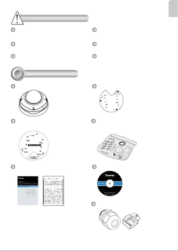
Package Contents
FD8363
Alignment Sticker /
Ceiling Hole Template Sticker
Quick Installation Guide /
Warranty Card
Refer to your user's manual for the
operating temperature.
Do not touch the Network Camera
during a lightning storm.
Do not drop the Network Camera.
Mounting Plate
L-type Hex Key Wrench / Dessicant
Bag / DC Connector / Screws / Hex
Nut / Double-sided Tape / AV Cable
Software CD
Waterproof Connector & Bushing
EN - 1
2
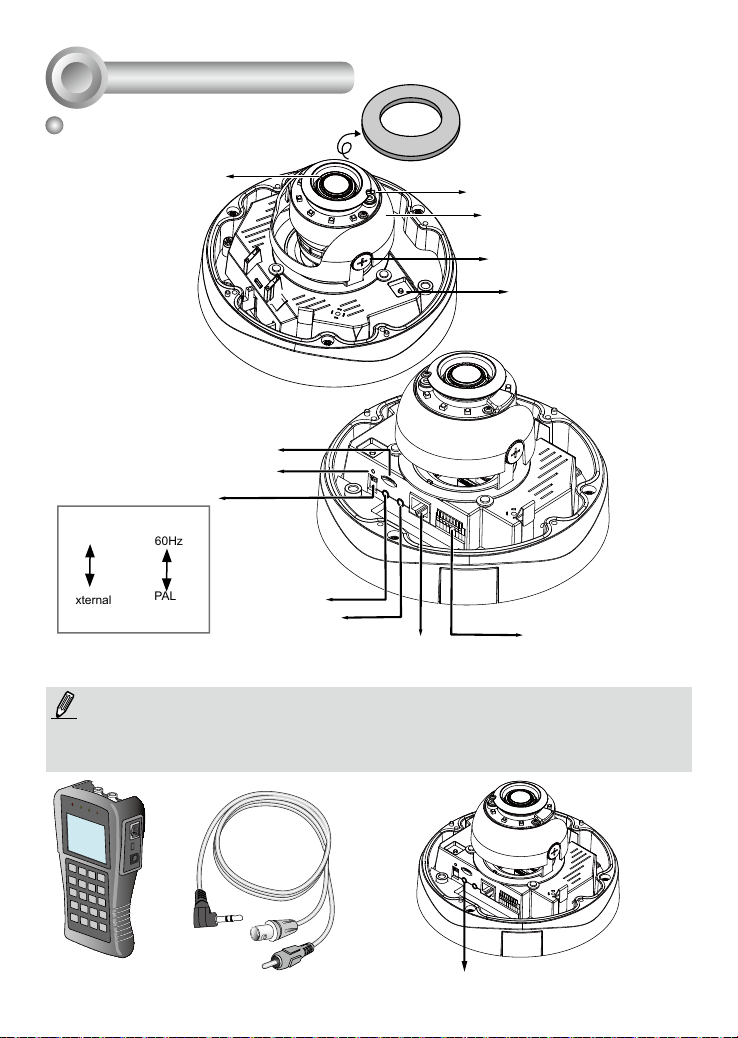
Physical Description
Inner View
Vari-focal Lens
Remove the foam pad
IR LEDs (8 units, effective up
to 15m)
Black Cover
Tilt Adjustment Screw
Auto Focus Button
Micro SD/SDHC/SDXC
Card Slot
Reset Button
Jumpers
1
Video Output
NTSC
60Hz
PAL
50Hz
2
Audio/Video
Out (green)
Microphone In
(pink)
Ethernet 10/100
General I/O Terminal
Block
Microphone
Internal
External
RJ45 Socket
1. There is no internal microphone. Connect an external microphone if you need
audio inputs.
2. Use the included AV cable to connect to a camera tester or LCD monitor to begin
initial setup.
LCD Monitor/
Camera tester
AV Out
EN - 2
Record the MAC address under the
camera base before installing the
camera.
Replace the side opening cover with the included
side outlet bushing if you want to route cables from
the side of camera. The 1/2" protection conduits
and tubing are separately purchased.
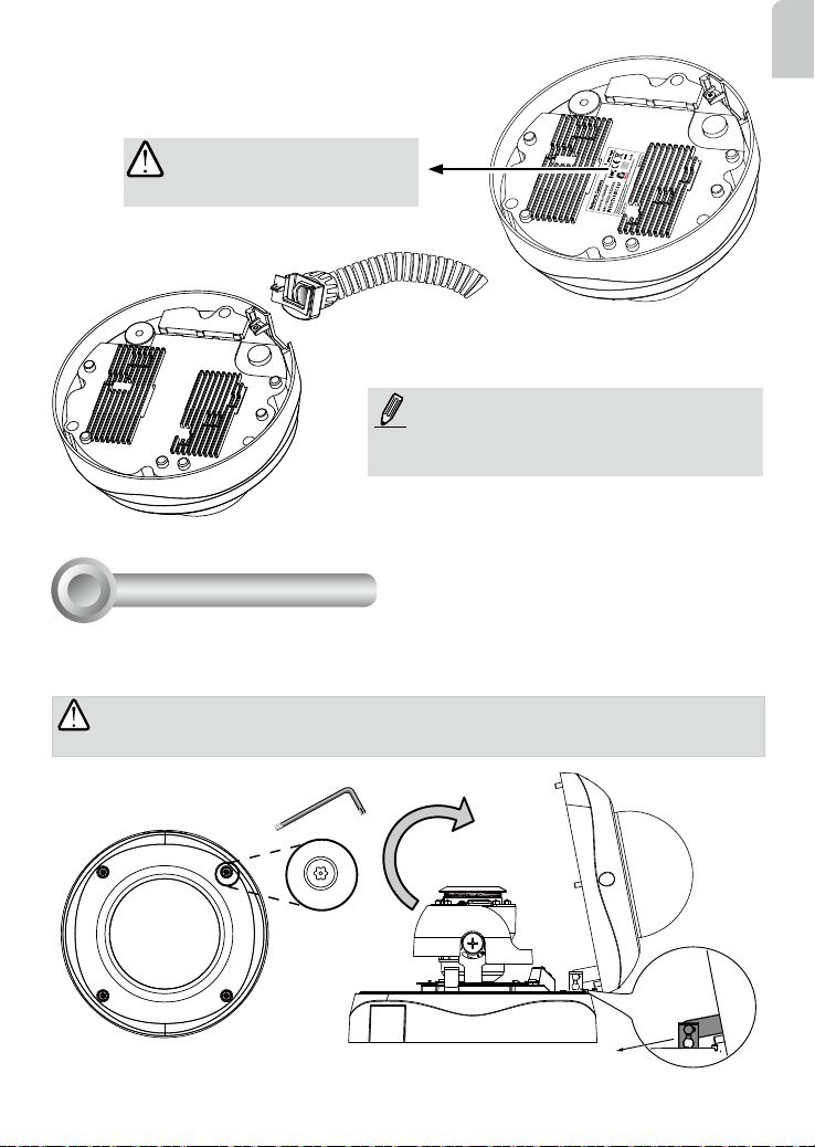
Hardware Installation
3
First, use the included T20 hex key wrench to loosen the four screws and detach the dome cover from
the camera base. Follow the steps below to install the camera either to a ceiling or a wall.
English
IMPORTANT:
process, physical injury could occur to your co-workers.
Dome cover should be removed because if it should fall during the installation
Top View
Dome Cover Retainer
EN - 3
Dome Cover
 Loading...