

Page 1
VIVOTEK Fixed Dome & Fisheye Series
Available from A1 Security Cameras
www.a1securitycameras.com email: sales@a1securitycameras.com
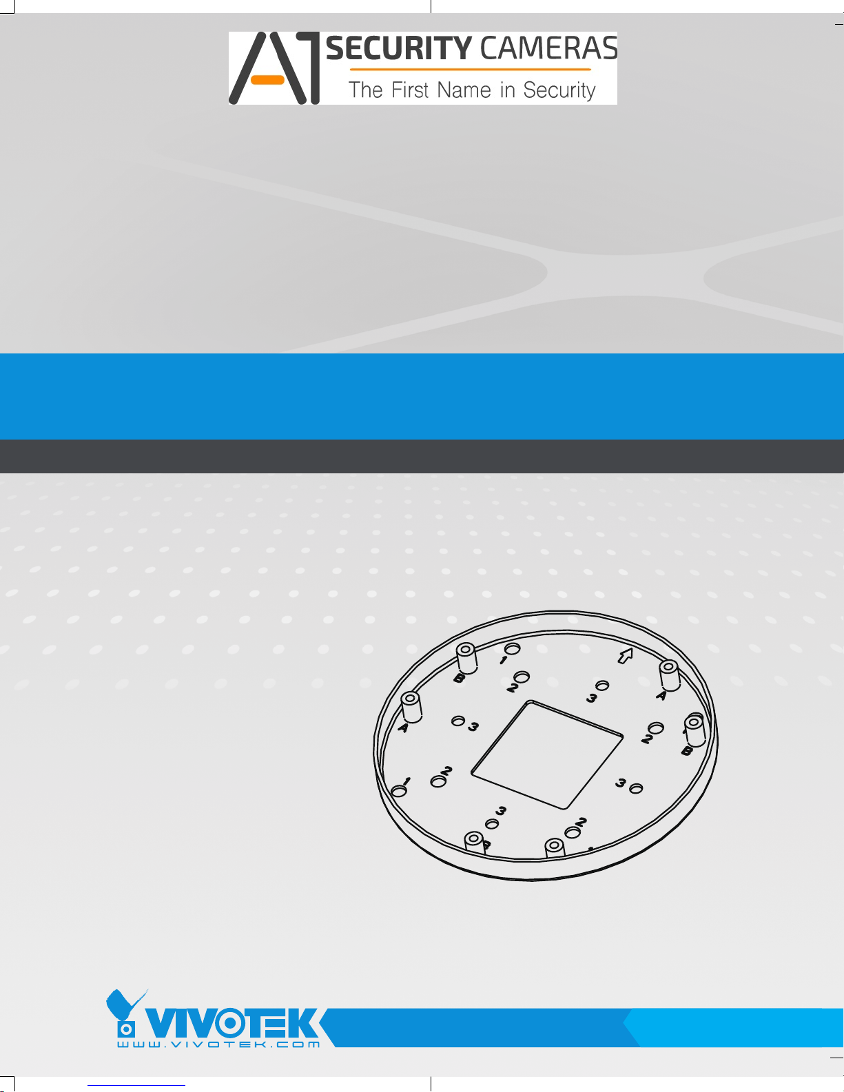
Mounting Cap
Installation Guide
Using AM-514 mounting cap
and compatible accessories
Ordering part no.:
100138800G ASS'Y KIT,AM-514_V01
Part no.: 625031700G
Rev. 1.0
IP Surveillance
Page 2
Revision History:
Available from A1 Security Cameras
www.a1securitycameras.com email: sales@a1securitycameras.com
* Rev. 1.0: Initial Release
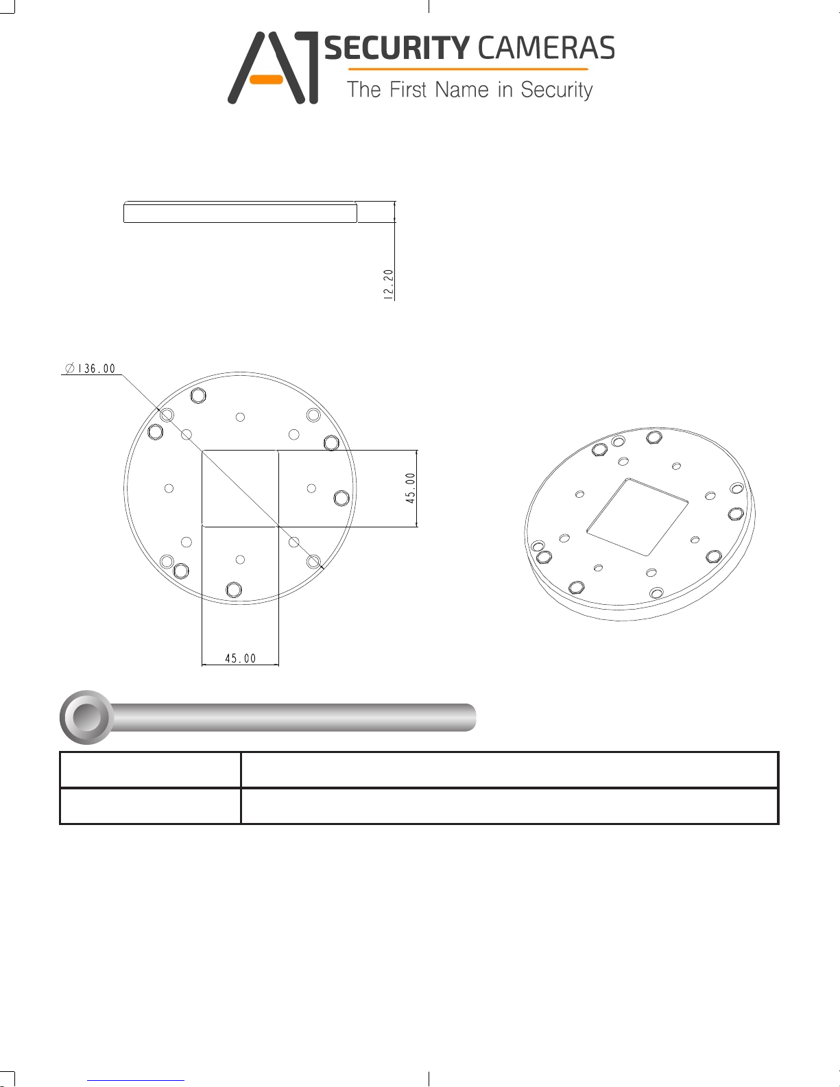
AM-514 Mounting Cap Mechanical Drawings
Compatible VIVOTEK Cameras
I
Fixed Dome series
Fisheye
You may also refer to VIVOTEK's website for the list of supported models. Support for other models can
be available through time.
Package Contents: AM-514, Installation Guide, 4x panhead M4x7, 2x copper spacer,
FD8167 / FD8138-H / FD9171 / FD816B / FD8182
FE8174
2
Page 3
II
Available from A1 Security Cameras
www.a1securitycameras.com email: sales@a1securitycameras.com
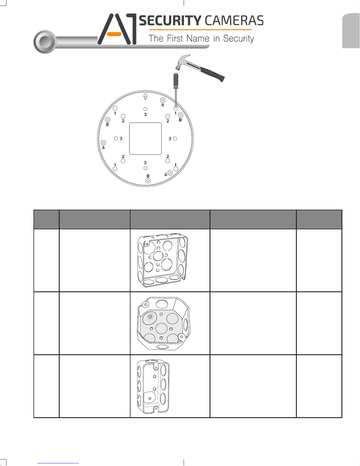
Installation
Mounting Hole Denitions
User a hammer and screwdriver to open the
knock out holes you prefer to use.
Above are the locations of different groups of mounting holes for matching different junction
boxes:
English
Hole
Type
1
2
3
Applicable Box Drawings Screw No. of
screws
4" square box
#8-32, L15
(User-supplied)
2
4" octagon box
#8-32, L15
(User-supplied)
2
1" single gang box
#6-32, L15
(User-supplied)
2
3
Page 4

Hole
Available from A1 Security Cameras
www.a1securitycameras.com email: sales@a1securitycameras.com
Type
A
B
Applicable Cameras Screw No. of screws
FD9171, FD816B,
FD8182
#8-32, L15 (User-supplied)
2
FD8167, FD8138-H
#8-32, L15 (User-supplied)
2
1
FE8174
#6-32, L15 (User-supplied) + copper spacers
2
NOTE:
1. Route cables before you secure the accessories to a wall.
2. For details on the cable connections with network cameras, please refer to their Quick
Installation Guide.
Installing the Mounting Cap
1. Route cables through the junction box.
4
Page 5

2. If installing FE8174 sheye camera, install two copper spacers to holes 1's.
Available from A1 Security Cameras
www.a1securitycameras.com email: sales@a1securitycameras.com
3. Install the mount cap to the junction box. Use screw holes specied on page 3
depending on the type of junction box.
English
Hole 1
Hole 1
5
Page 6

4-1. FE8174.
Available from A1 Security Cameras
www.a1securitycameras.com email: sales@a1securitycameras.com
4-1-1. Install the camera to the mount cap by fastening two screws to the threaded holes
on the copper spacers.
4-1-2. Connect the cables and install the top cover.
6
Page 7

4-2. FD9171/FD816B/FD8182.
Available from A1 Security Cameras
www.a1securitycameras.com email: sales@a1securitycameras.com
4-2-1. Install the camera to the mount cap by fastening three screws. You will need to
remove the plastic tab on the routing hole in order to pass the cables.
English
4-2-2. Connect the cables and install the top cover.
7
Page 8

4-3. FD8167/FD8138H.
Available from A1 Security Cameras
www.a1securitycameras.com email: sales@a1securitycameras.com
4-3-1. Fasten screws to the mounting cap. Do not completely tighten the screws. Leave
part of the screws out.
4-3-2. Install the camera to the mounting cap by turning it counter-clockwise so that the
screw heads t in the keyhole slots. Fasten the screws, and then connect the cables.
4-3-3. Install the dome cover. Tune the focus, and refer to the
documentation that came with your cameras for the rest of
conguration details.
8
 Loading...