

Page 1

Lens retention screw
FD8156/8168
Quick Installation Guide
Part no.: 625024500G
Lens
Reset button
Microphone
MicroSD card
slot
NOTE:
1. The camera can only be powered by Power
over Ethernet (PoE).
2. The camera can only be installed in an
indoor environment.
Loosen the retention screw
to change shooting angle.
Before you begin:
You can connect the
Ethernet cable to a PC or
laptop for a live view. (See
page 5). Raise the camera
to the estimated position,
and evaluate the eld of
view by turning the mount
bracket and lens.
1
Status LED
Shooting
direction
Page 2

Ceiling Mount Procedure:
1. Attach the alignment sticker to
a preferred location, with the
Front mark facing the shooting
direction.
3. Install the mount bracket
using the self-tapping
screws.
30mm
Front mark
2. Drill a 30mm cabling
hole if preferred.
Mount
bracket
4. Pass the Ethernet cable through the cabling hole or along the
wall.
5. Join the camera with the mount bracket by
sliding it along the grooves to t into place.
2
Page 3

Wall Mount Procedure:
1. Attach the mount bracket to the wall-mount bracket, with
the Front mark facing the shooting direction. Note that you
should turn the bracket to aim the Front mark at the shooting
direction.
2. Attach the alignment sticker to a preferred location.
3. Mark the drill holes and drive screws into the wall. Leave
15mm of the screws off the wall surface.
4. If preferred, drill a 30mm cabling hole on the wall.
30mm
15mm
3
Page 4
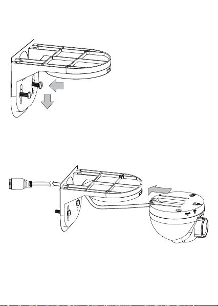
5. Hang the bracket onto the screws. You can then fasten the
screws to wall.
6. Connect the Ethernet cable and pass cable through the
hole. Join the camera with the bracket by sliding it along the
grooves.
4
Page 5
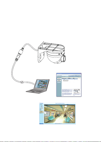
Tune the focus:
Connect the camera to a PC or laptop. Install and use the IW2
utility to discover your camera on LAN. Double-click on the
camera entry to open a web session.
If your image appears to be out of focus, use the included focus
adjustment tool to tune the focus.
IW2
00-02-D1-73-02-02 192.168.5.151 FD8168
0002D1730202
Browser
5
Page 6

Carefully place the tool onto the lens, and turn clockwise or
counter-clockwise to adjust the focus.
NOTE:
Press the release button if you should need to re-install the
camera.
Release button
6
Page 7

This page is intentionally left blank.
7
Page 8

8
 Loading...