

Page 1
Fixed Dome
FD8131
Network Camera
User’s Manual
Vari-focal • Compact Design • Micro SD/SDHC
Rev. 1.0
Rev. 1.0
Page 2

VIVOTEK
Table of Contents
Overview........................................................................................................................................4
Revision History ...................................................................................................................................... 4
Read Before Use ..................................................................................................................................... 5
Package Contents ................................................................................................................................... 5
Symbols and Statements in this Document ............................................................................................. 5
Physical Description ................................................................................................................................ 6
Installation ............................................................................................................................................... 7
Network Deployment ............................................................................................................................... 9
Software Installation .............................................................................................................................. 12
Ready to Use ......................................................................................................................................... 13
Completion ............................................................................................................................................ 15
Accessing the Network Camera ..................................................................................................16
Using Web Browsers ............................................................................................................................. 16
Using RTSP Players .............................................................................................................................. 19
Using 3GPP-compatible Mobile Devices ............................................................................................... 20
Using VIVOTEK Recording Software .................................................................................................... 21
Main Page ...................................................................................................................................22
Client Settings .............................................................................................................................27
Conguration ...............................................................................................................................29
System > General settings .................................................................................................................... 30
System > Homepage layout ................................................................................................................. 32
System > Logs ...................................................................................................................................... 35
System > Parameters ........................................................................................................................... 36
System > Maintenance .......................................................................................................................... 37
Media > Image .................................................................................................................................... 41
Media > Video ....................................................................................................................................... 46
Media > Video ....................................................................................................................................... 47
Network > General settings ................................................................................................................... 51
Network > Streaming protocols ........................................................................................................... 58
Network > SNMP (Simple Network Management Protocol) .................................................................. 66
Security > User Account ........................................................................................................................ 67
Security > HTTPS (Hypertext Transfer Protocol over SSL) ........................................................68
Security > Access List ......................................................................................................................... 73
PTZ > PTZ settings ............................................................................................................................... 78
Event > Event settings........................................................................................................................... 82
Applications > Motion detection............................................................................................................. 95
Applications > DI and DO ...................................................................................................................... 98
Applications > Tampering detection ...................................................................................................... 98
Recording > Recording settings ........................................................................................................... 99
Local storage > SD card management ................................................................................................ 104
Local storage > Content management ................................................................................................ 105
Appendix ...................................................................................................................................108
URL Commands for the Network Camera ........................................................................................... 108
Technical Specications ......................................................................................................................155
2 - User's Manual
Page 3

VIVOTEK
Technology License Notice .......................................................................................................................156
Electromagnetic Compatibility (EMC) .......................................................................................................157
User's Manual - 3
Page 4

VIVOTEK
Overview
VIVOTEK FD8131 is an easy-to-use xed dome network camera specically designed for indoor
security applications with a compact, stylish housing. Equipped with a 1MP sensor enabling
viewing resolution of 1280x800 at 30 fps, users need look no further for an all-in-one camera
capable of capturing high quality HD video.
This camera supports the industry-standard H.264 compression technology, drastically reducing
le sizes and conserving valuable network bandwidth. With MPEG-4 and MJPEG compatibility
also included, video streams can also be transmitted in any of these formats for versatile
applications. The streams can also be individually configured to meet different constraints,
thereby further reducing bandwidth and storage requirements. Users can thus receive multiple
streams simultaneously in different resolutions, frame rates, and image qualities for viewing on
different platforms.
With the vari-focal lens, the FD8131 provides users the freedom to adjust the eld of view in
accordance with their application. Also included are a number of advanced features which are
standard for VIVOTEK cameras, including tamper detection, MicroSD/SDHC card slot, 802.3af
compliant PoE, and VIVOTEK’s 32-channel recording software. With all of these capabilities, the
FD8131 provides the best value in IP surveillance for indoor applications such as ofces, banks,
and retail stores.
Revision History
■ Rev. 1.0: Initial release
4 - User's Manual
Page 5
VIVOTEK
i
Read Before Use
The use of surveillance devices may be prohibited by law in your country. The Network Camera
is not only a high-performance web-ready camera but can also be part of a exible surveillance
system. It is the user’s responsibility to ensure that the operation of such devices is legal before
installing this unit for its intended use.
It is important to first verify that all contents received are complete according to the Package
Contents listed below. Take note of the warnings in the Quick Installation Guide before the Network
Camera is installed; then carefully read and follow the instructions in the Installation chapter to
avoid damage due to faulty assembly and installation. This also ensures the product is used
properly as intended.
The Network Camera is a network device and its use should be straightforward for those who
have basic networking knowledge. It is designed for various applications including video sharing,
general security/surveillance, etc. The Configuration chapter suggests ways to best utilize the
Network Camera and ensure proper operations. For creative and professional developers, the URL
Commands of the Network Camera section serves as a helpful reference to customizing existing
homepages or integrating with the current web server.
Package Contents
■ FD8131
■ Alignment sticker
■ RJ45 Female/Female Coupler / Screws / Clamp Core
■ Software CD
■ Warranty Card
■ Quick Installation Guide
Because this model supports PoE, DC adapter is optional and is user-supplied.
Symbols and Statements in this Document
INFORMATION: provides important messages or advices that might help prevent
inconvenient or problem situations.
NOTE: Notices provide guidance or advices that are related to the functional integrity of
the machine.
Tips: Tips are useful information that helps enhance or facilitae an installation, function,
or process.
WARNING! or IMPORTANT: These statements indicate situations that can be dangerous
or hazardous to the machine or you.
Electrical Hazard: This statement appears when high voltage electrical hazards might
occur to an operator.
User's Manual - 5
Page 6
VIVOTEK
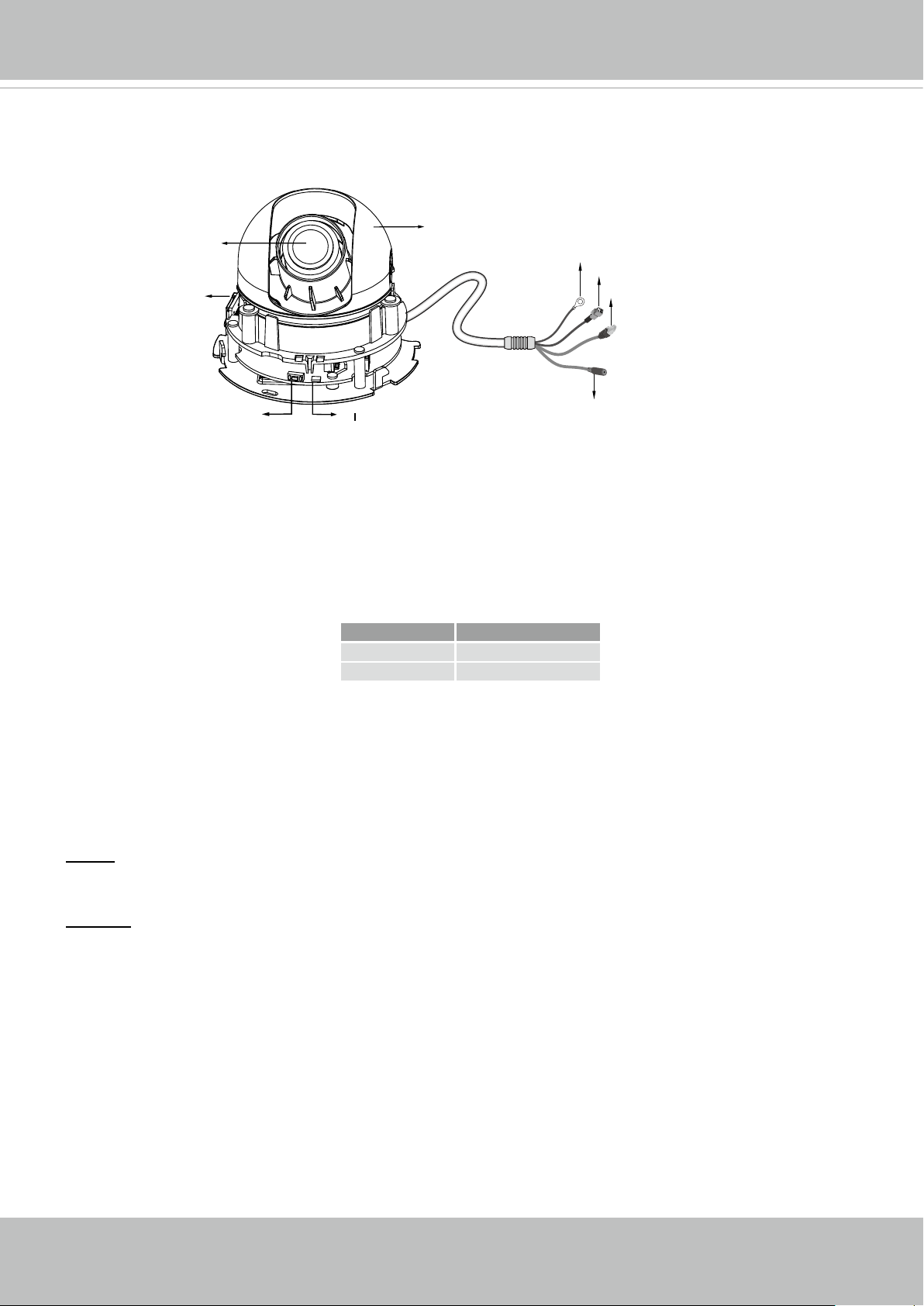
Physical Description
Lens
Ground wire
General I/O Terminal Block
Black Cover
MicroSD/SDHC
Ethernet 10/100 RJ45 Plug
Card Slot
Reset Button
Status LED
Power Cord Socket
General I/O Terminal Block
This Network Camera provides a general I/O terminal block which is used to connect external
input / output devices. The pin denitions are described below. The 24V AC can be used as an
alternate power source.
Pin Name
+ Digital Input +
- Digital Input -
Hardware Reset
The reset button is used to reset the system or restore the factory default settings. Sometimes
resetting the system can return the camera to normal operation. If the system problems remain
after reset, restore the factory settings and install again.
Reset: Press and release the recessed reset button with a straightened paper clip. Wait for the
Network Camera to reboot.
Restore: Press and hold the recessed reset button until the status LED rapidly blinks. Note that
all settings will be restored to factory default. Upon successful restore, the status LED will blink
green and red during normal operation.
Micro SD/SDHC Card Capacity
This network camera is compliant with Micro SD/SDHC 16GB / 8GB and other preceding
standard SD cards.
6 - User's Manual
Page 7
VIVOTEK
Installation
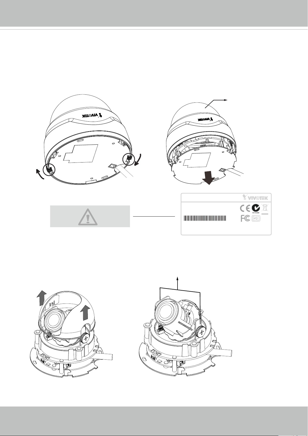
Removing Dome Cover
First, follow the instructions below to remove the dome cover. Flip the black retention tabs
in the counter-clockwise direction to release the dome cover (clockwise if you look from the
bottom up.)
Dome Cover
Record the MAC address before
installing the camera.
Then remove the black cover as shown below.
Tilt Adjustment Screw
Network Camera
Model No: FD8131
MAC:0002D1730202
This device complies with part 15 of the FCC rules. Operation is subject to the following two conditions:
(1)This device may not cause harmful interference, and
(2) this device must accept any interference received, including interference that may cause undesired operation.
Pat. 6,930,709
R oHS
Made in Taiwan
User's Manual - 7
Page 8
VIVOTEK
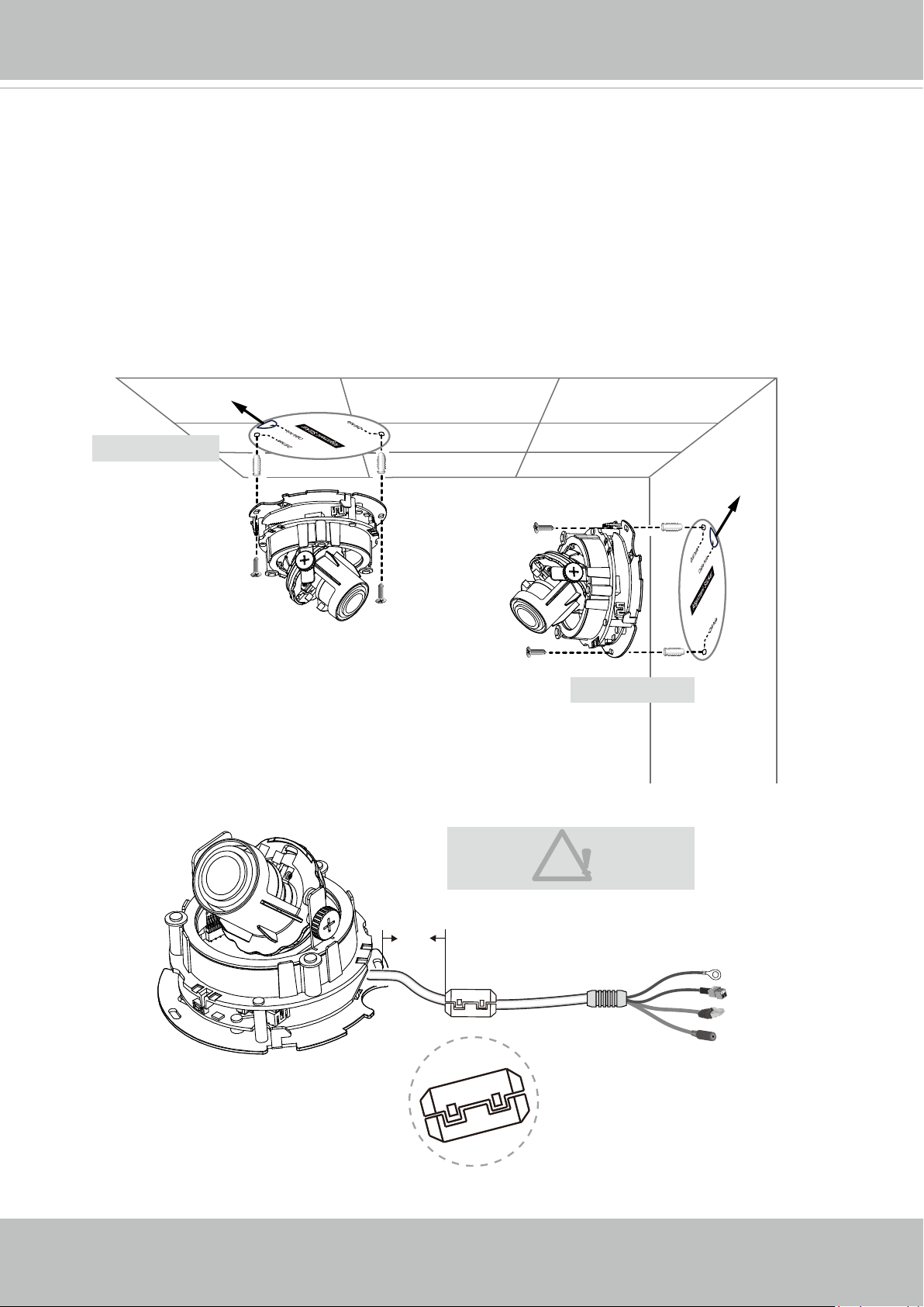
To install the camera to a ceiling or wall:
1. Attach the alignment sticker to the ceiling/wall.
2. Through the two circles on the sticker, drill two pilot holes into the ceiling/wall.
3. The Network Camera can be mounted with the cable routed through the ceiling/wall or
from the side. If you want to feed the cable through the ceiling/wall, drill a cable hole A as
shown in the above picture.
4. Hammer the supplied plastic anchors into the holes.
5. Align the two holes on each side of the camera base with the two plastic anchors on the
ceiling/wall, insert the supplied screws to corresponding holes and secure them with a
screwdriver.
A
Ceiling Mount
A
Wall Mount
6. Buckle the supplied clamp core onto the cable to prevent the EMI radiation.
The clamp core should be away
from the device at least 5 cm.
5 cm
8 - User's Manual
Page 9
VIVOTEK
Network Deployment
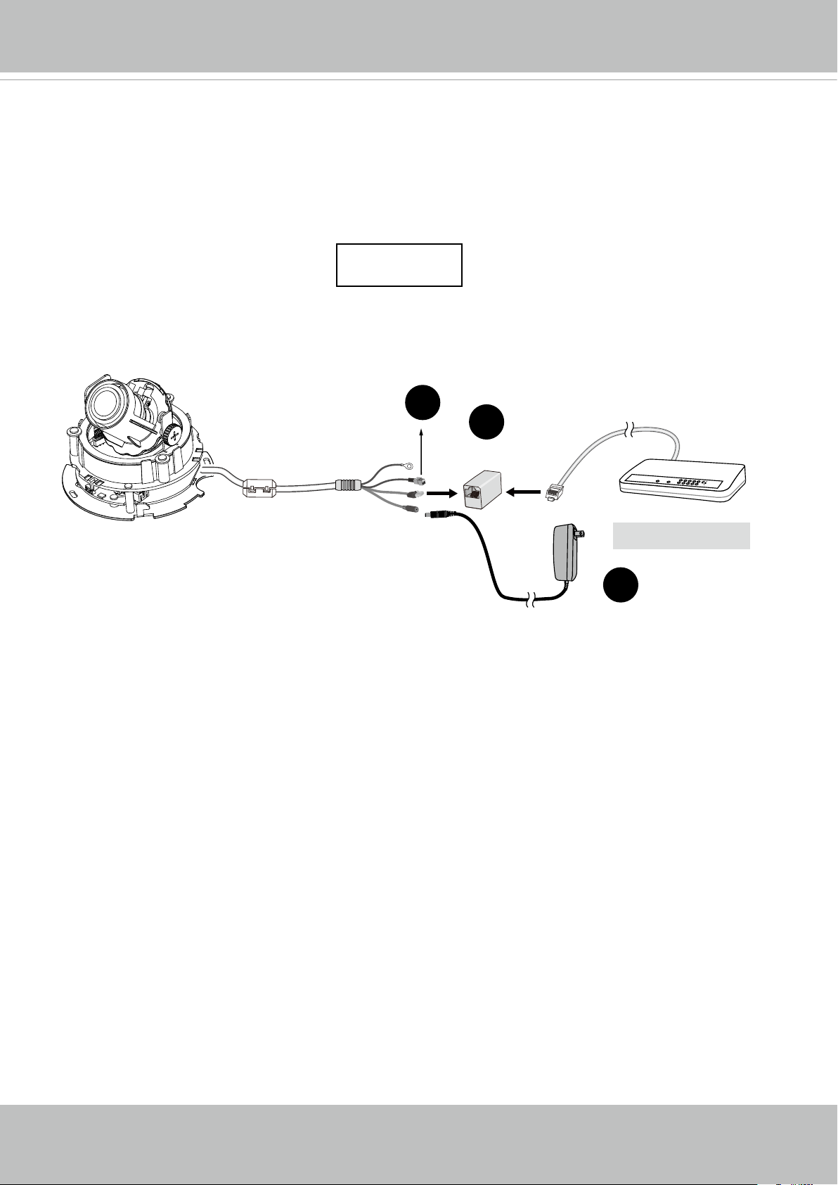
General Connection (without PoE)
This section explains how to congure the Network Camera to an Internet connection.
1. If you have external devices such as sensors and alarms, make the connection from the
general I/O terminal block.
2. Use the supplied RJ45 female/female coupler to connect the Network Camera to a switch.
3. Connect the power cable from the Network Camera to a power outlet. The DC adapter is
user-supllied.
+ : Digital input
- : Digital input
1
2
POW
ER
C
O
LL
I
S
ION
1
2
3
4
5
Ethernet Switch
3
L
I
N
K
RE
CEIVE
PARTITIO
N
User's Manual - 9
Page 10
VIVOTEK
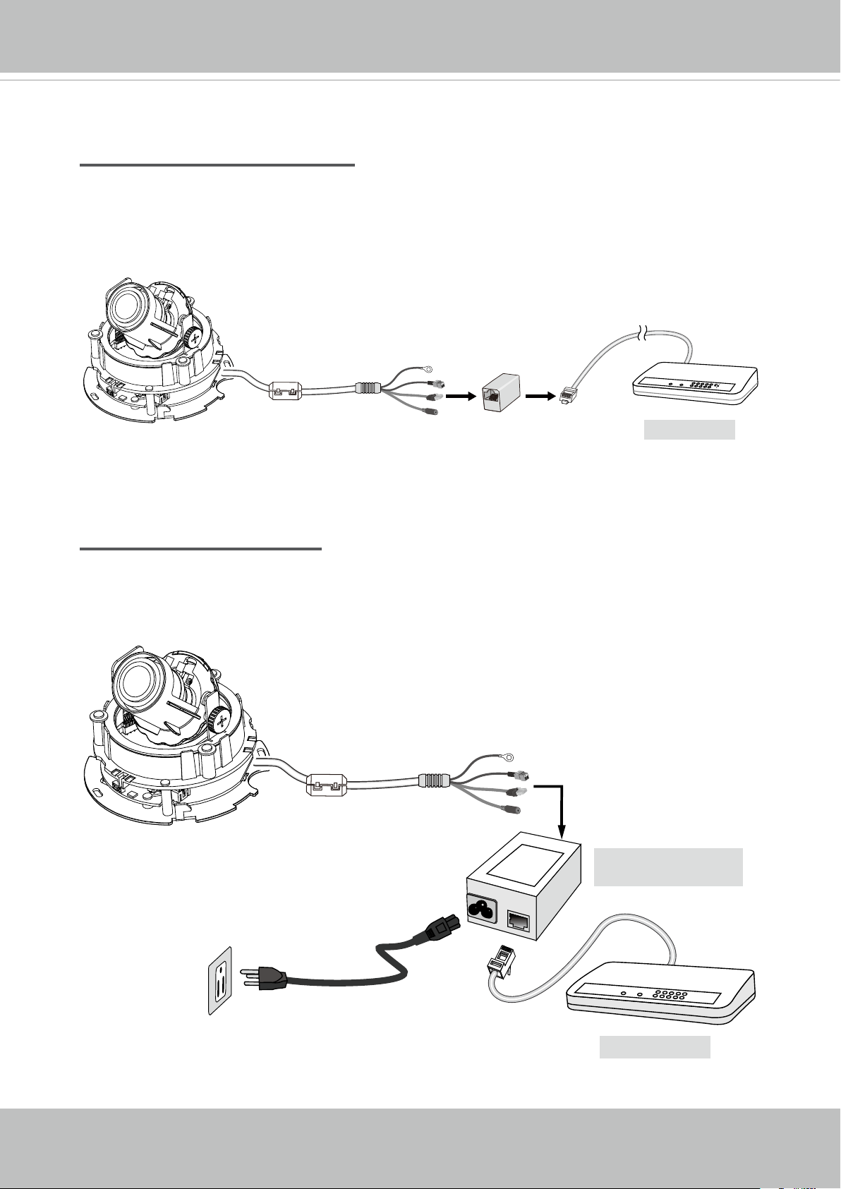
Set up the Network Camera through Power over Ethernet (PoE)
When using a PoE-enabled switch
The Network Camera is PoE-compliant, allowing transmission of power and data via a
single Ethernet cable. Follow the below illustration to connect the Network Camera to a
PoE-enabled switch via Ethernet cable.
power + data transmission
POW
ER
C
O
LL
I
S
ION
1
PARTITIO
2
3
4
5
PoE Switch
L
I
N
K
RE
CEIVE
N
When using a non-PoE switch
If your switch/router does not support PoE, use a PoE power injector (optional) to connect
between the Network Camera and a non-PoE switch.
PoE Power Injector
(optional)
10 - User's Manual
POW
ER
C
O
LL
I
S
ION
1
RECEIVE
PARTITIO
2
3
4
5
Non-PoE Switch
L
I
N
K
N
Page 11
VIVOTEK
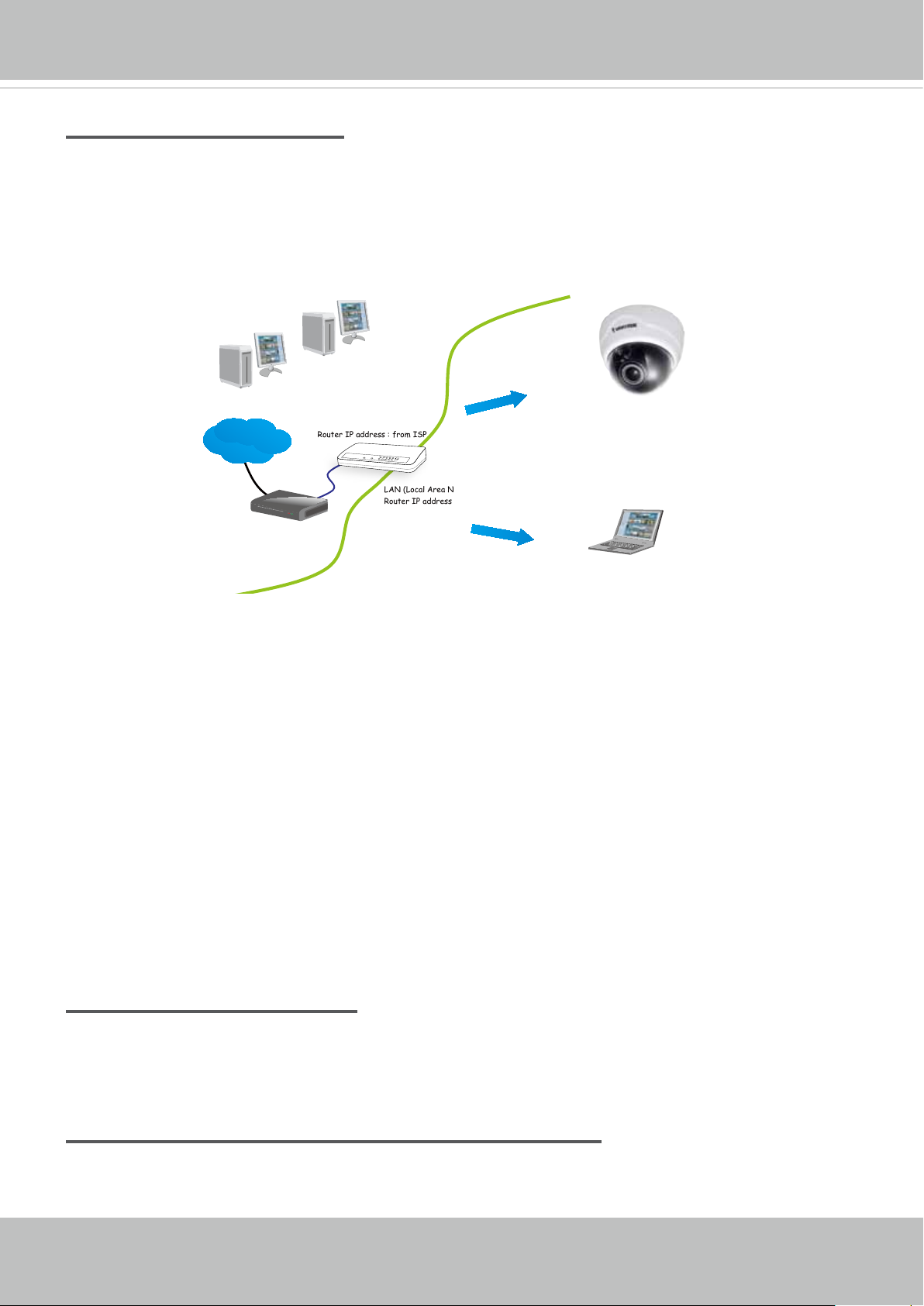
Internet connection via a router
Before setting up the Network Camera over the Internet, make sure you have a router and follow
the steps below.
1. Connect your Network Camera behind a router, the Internet environment is illustrated below.
Regarding how to obtain your IP address, please refer to Software Installation on page 12 for
details.
IP address : 192.168.0.3
Subnet mask : 255.255.255.0
Default router : 192.168.0.1
IP address : 192.168.0.2
Subnet mask : 255.255.255.0
Default router : 192.168.0.1
Internet
Cable or DSL Modem
WAN (Wide Area Network )
Router IP address : from ISP
LINK
POWER
COLLISION
RECEIVE
1
2
PARTITION
3
4
5
LAN (Local Area Network)
Router IP address : 192.168.0.1
2. In this case, if the Local Area Network (LAN) IP address of your Network Camera is
192.168.0.3, please forward the following ports for the Network Camera on the router.
■ HTTP port: default is 80
■ RTSP port: default is 554
■ RTP port for audio: default is 5558
■ RTCP port for audio: default is 5559
■ RTP port for video: default is 5556
■ RTCP port for video: default is 5557
If you have changed the port numbers on the Network page, please open the ports
accordingly on your router. For information on how to forward ports on the router, please refer
to your router’s user’s manual.
3. Find out the public IP address of your router provided by your ISP (Internet Service Provider).
Use the public IP and the secondary HTTP port to access the Network Camera from the
Internet. Please refer to Network Type on page 52 for details.
Internet connection with static IP
Choose this connection type if you are required to use a static IP for the Network Camera.
Please refer to LAN setting on page 51 for details.
Internet connection via PPPoE (Point-to-Point over Ethernet)
Choose this connection type if you are connected to the Internet via a DSL Line. Please refer to
PPPoE on page 52 for details.
User's Manual - 11
Page 12
VIVOTEK
Software Installation
Installation Wizard 2 (IW2), free-bundled software included on the product CD, helps you set up
your Network Camera on the LAN.
IW
1. Install IW2 under the Software Utility directory from the software CD.
Double-click the IW2 shortcut on your desktop to launch the program.
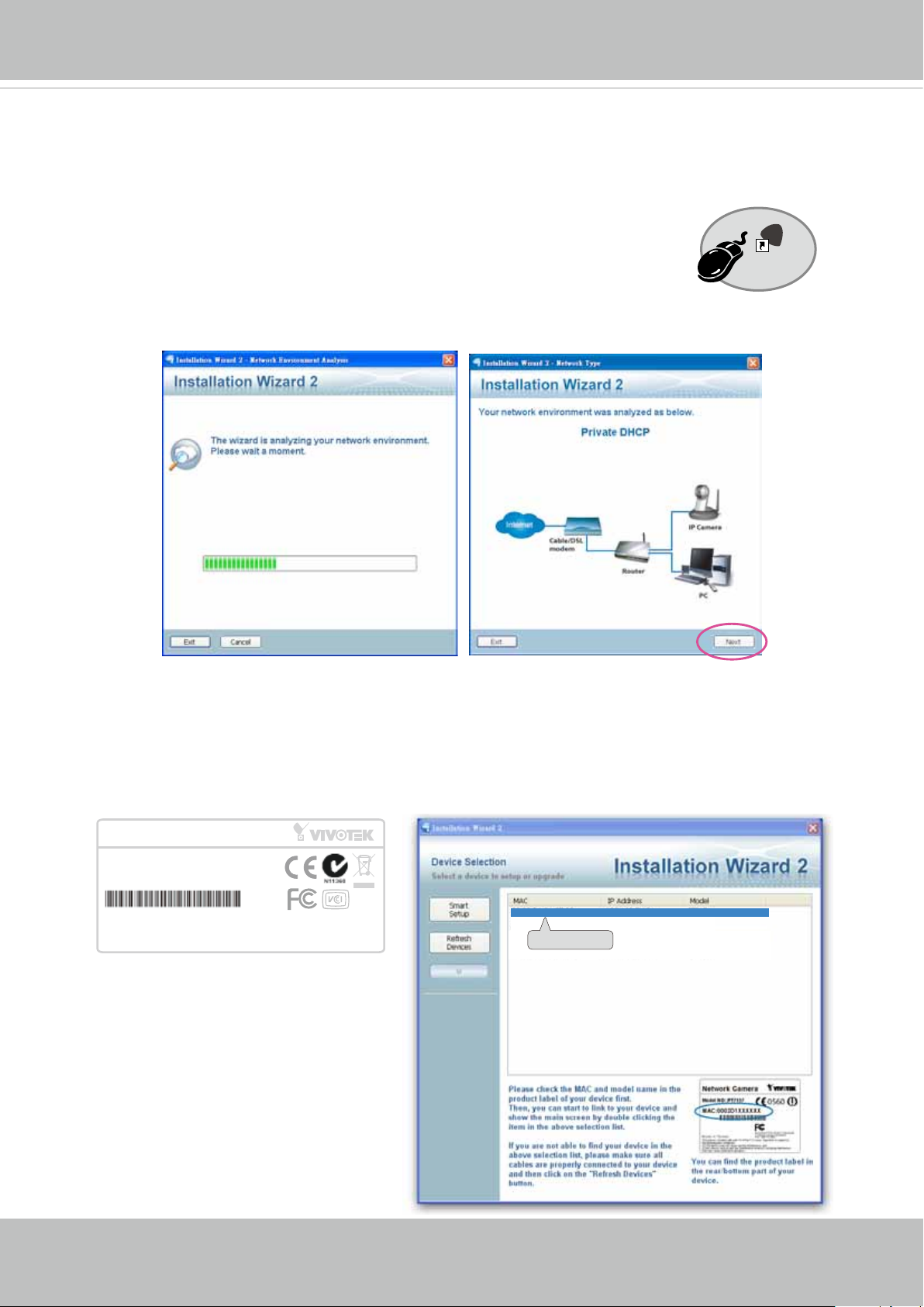
2. The program will conduct an analysis of your network environment.
After your network environment is analyzed, please click Next to continue the program.
2
Installation
Wizard 2
3. The program will search for all VIVOTEK network devices on the same LAN.
4. After a brief search, the installer window will prompt. Click on the MAC and model name
that matches the one printed on the product label. You can then double-click on the address to
open a management session with the Network Camera.
Network Camera
Model No: FD8131
MAC:0002D1730202
This device complies with part 15 of the FCC rules. Operation is subject to the following two conditions:
(1)This device may not cause harmful interference, and
(2) this device must accept any interference received, including interference that may cause undesired operation.
Pat. 6,930,709
R o HS
Made in Taiwan
00-02-D1-73-02-02 192.168.5.151 FD8131
0002D1730202
12 - User's Manual
Page 13
VIVOTEK
Ready to Use
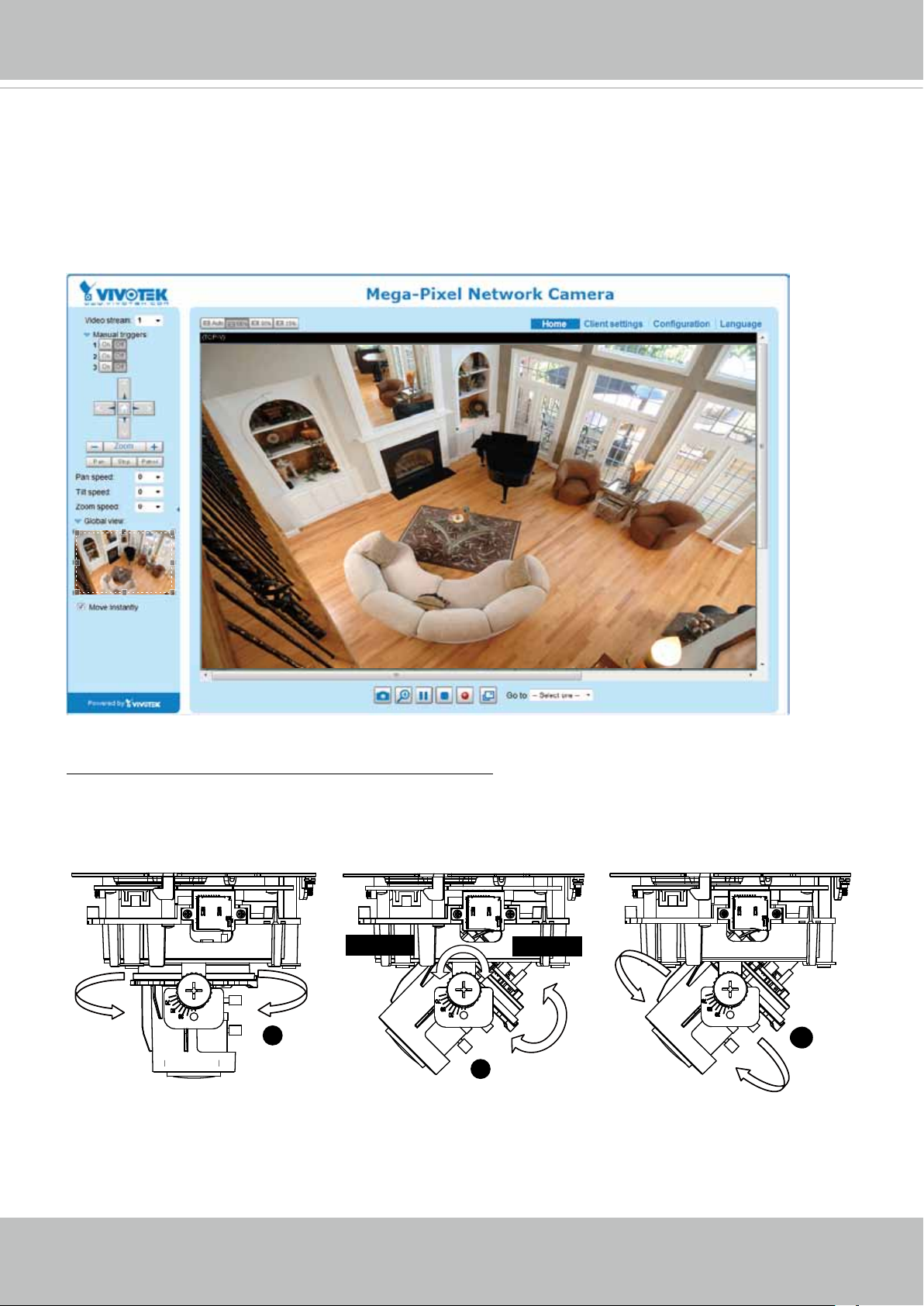
1. A browser session with the Network Camera should prompt as shown below.
2. You should be able to see live video from your camera. You may also install the 32-channel
recording software from the software CD in a deployment consisting of multiple cameras. For
its installation details, please refer to its related documents.
To adjust the viewing angle -- 3-axis mechanism design
1. Loosen the tilt adjustment screws and then turn the lens module up or down, or swing left or
right. Upon completion, tighten the screw.
2. Turn the lens to adjust the image orientation.
Loosen
1
Tighten
3
2
Pan 350°
Tilt 70°
Rotate 340°
User's Manual - 13
Page 14
VIVOTEK
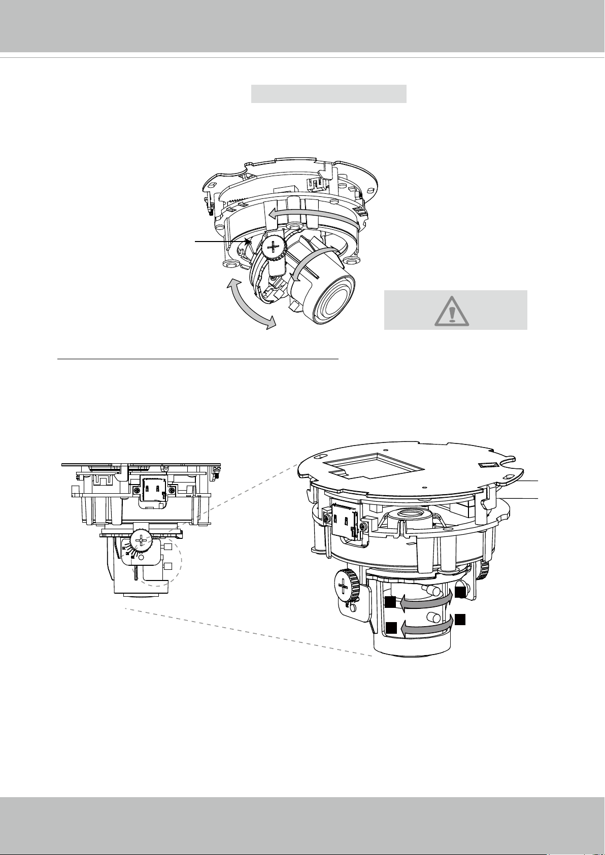
3-axis Mechanism Design
The sophisticated 3-axis mechanism design offers very exible, easy hardware installation
for either ceiling or wall mount.
Pan 350°
Tilt Adjustment Screw
Rotate 340°
DO NOT over rotate the lens.
Tilt 70°
Doing so will damage the
camera lens module.
To adjust the zoom factor and focus range
1. Loosen the zoom controller and then adjust zoom factor by moving the controller left
and right. Upon completion, tighten the zoom controller screw.
2. Loosen the focus controller and then adjust focus range by moving the controller left
and right. Upon completion, tighten the focus controller screw.
T
N
W
8
14 - User's Manual
Page 15
VIVOTEK
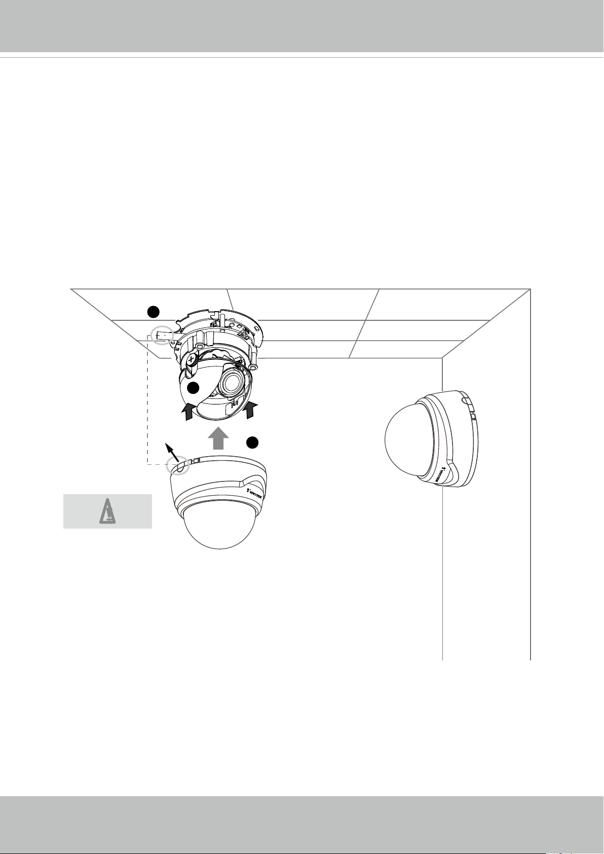
Completion
1. Align the inner side of the black cover with the notches on both sides of the lens, x the
black cover.
2. If you choose to feed the cable through the ceiling/wall, arrange the cable neatly through
the cable hole. If you choose to feed the cable from the side, remove plate B.
3. Attach the dome cover to the camera as shown below. The dome cover cannot be
attatched if installed in the wrong orientation. Align the side cover (or side cutout) with
where the cable comes out from the camera. Push the dome cover to join with the
camera.
4. Finally, make sure all parts of the camera are securely installed.
2
Be aware of
the cable route!
B
1
3
User's Manual - 15
Page 16
VIVOTEK
Accessing the Network Camera
This chapter explains how to access the Network Camera through web browsers, RTSP players,
3GPP-compatible mobile devices, and VIVOTEK recording software.
Using Web Browsers
Use Installation Wizard 2 (IW2) to access the Network Cameras on LAN.
If your network environment is not a LAN, follow these steps to access the Netwotk Camera:
1. Launch your web browser (e.g., Microsoft® Internet Explorer or Mozilla Firefox).
2. Enter the IP address of the Network Camera in the address eld. Press Enter.
3. The live video will be displayed in your web browser.
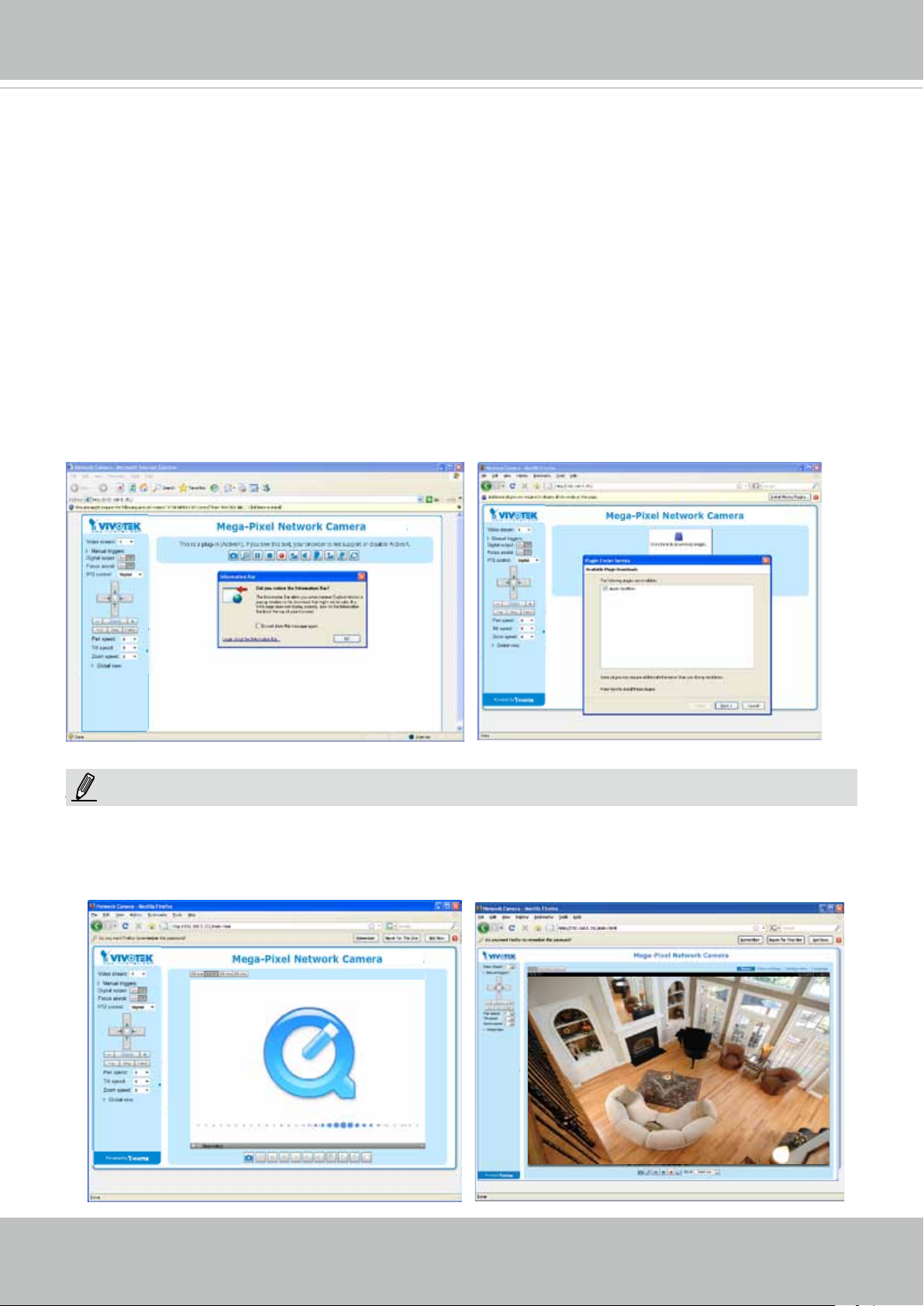
4. If it is the rst time installing the VIVOTEK network camera, an information bar will prompt as
shown below. Follow the instructions to install the required plug-in on your computer.
NOTE
► For Mozilla Firefox or Netscape users, your browser will use Quick Time to stream the live
16 - User's Manual
NOTE:
video. If you don’t have Quick Time on your computer, please download it rst, then launch
the web browser.
Page 17
VIVOTEK
► By default, the Network Camera is not password-protected. To prevent unauthorized access,
it is highly recommended to set a password for the Network Camera.
For more information about how to enable password protection, please refer to Security on
page 67.
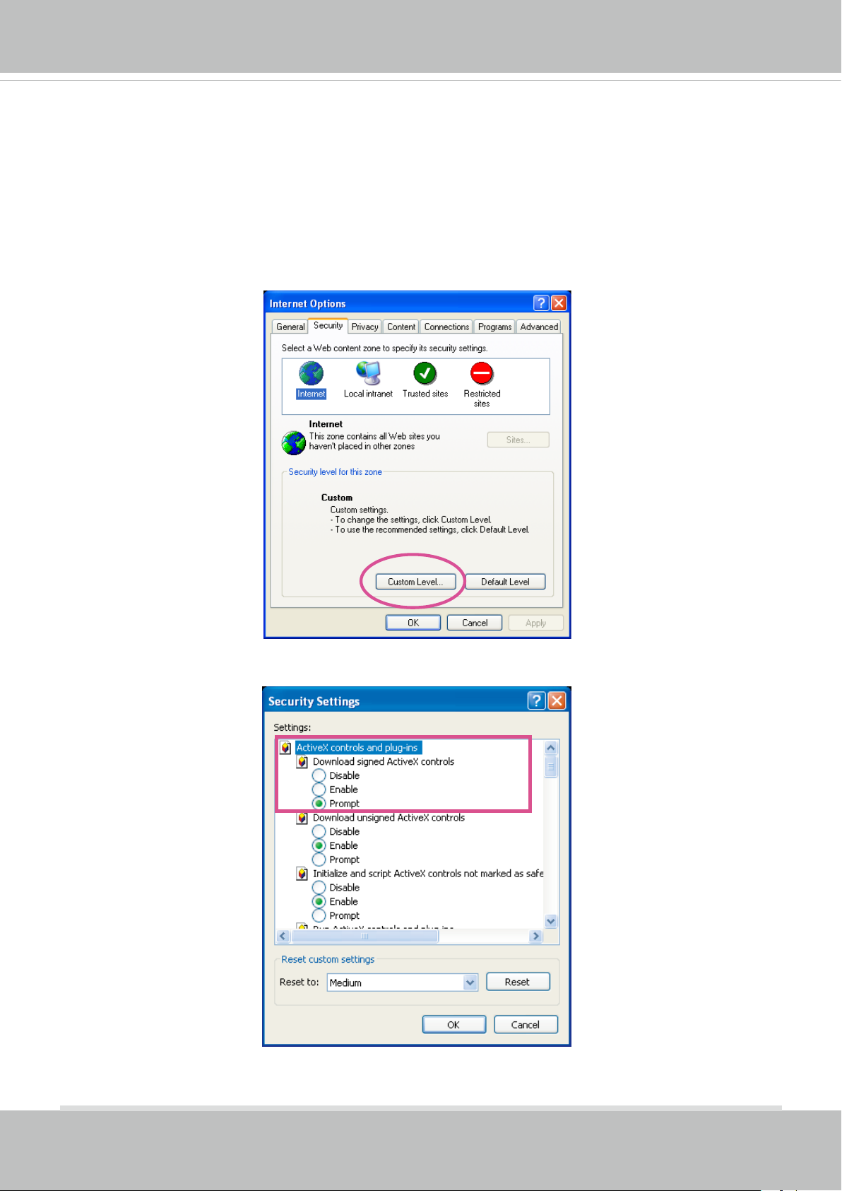
► If you see a dialog box indicating that your security settings prohibit running ActiveX®
Controls, please enable the ActiveX® Controls for your browser.
1. Choose Tools > Internet Options > Security > Custom Level.
2. Look for Download signed ActiveX® controls; select Enable or Prompt. Click OK.
3. Refresh your web browser, then install the ActiveX® control. Follow the instructions to
complete installation.
User's Manual - 17
Page 18
VIVOTEK
IMPORTANT!
Currently the Network Camera utilizes 32-bit ActiveX plugin. You CAN NOT
•
open a management/view session with the camera using a 64-bit IE browser.
If you encounter this problem, try execute the Iexplore.exe program from C:\
•
Windows\SysWOW64. A 32-bit version of IE browser will be installed.
On Windows 7, the 32-bit explorer browser can be accessed from here:
•
C:\Program Files (x86)\Internet Explorer\iexplore.exe
18 - User's Manual
Page 19
VIVOTEK
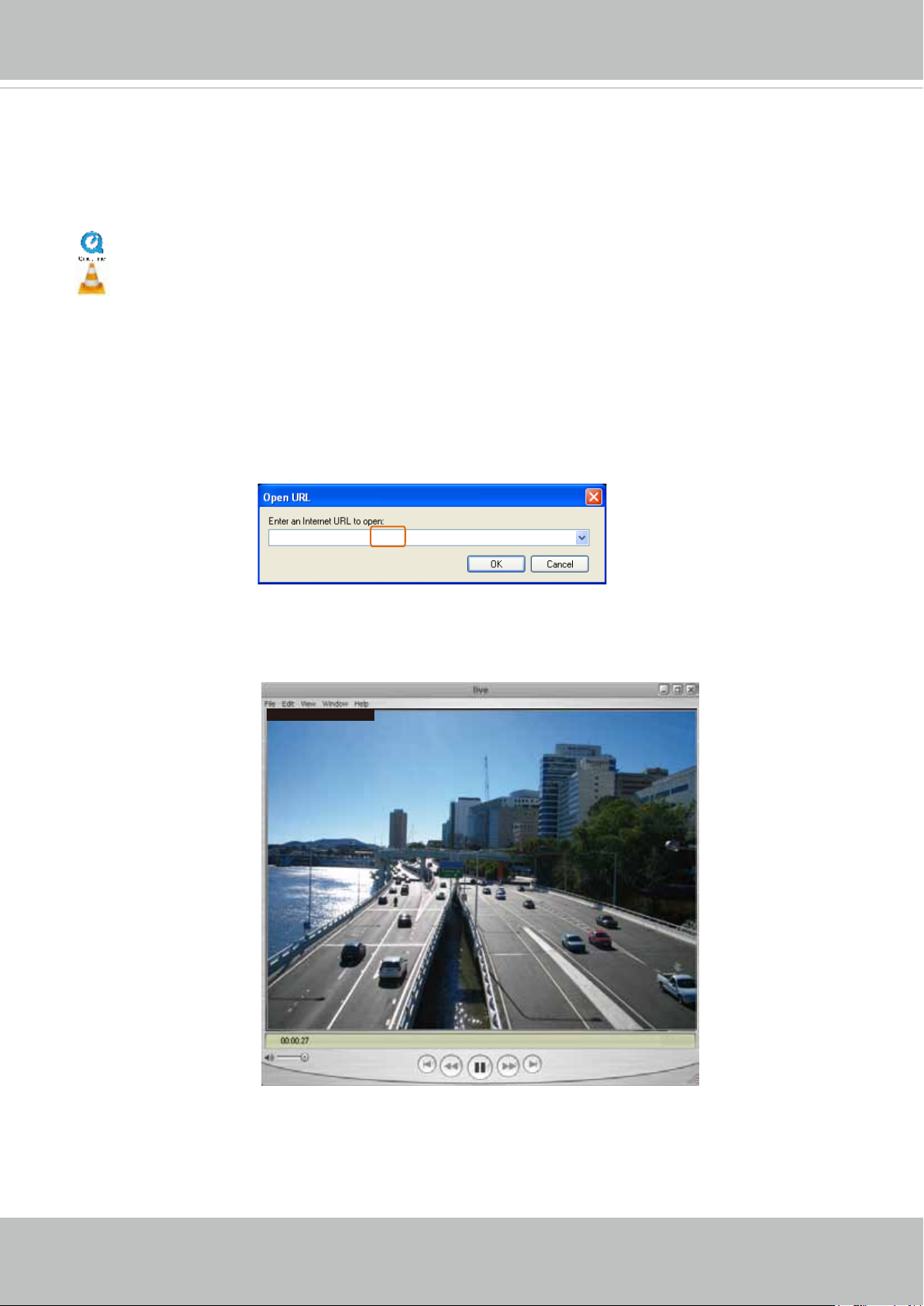
Using RTSP Players
To view the MPEG-4 streaming media using RTSP players, you can use one of the following
players that support RTSP streaming.
Quick Time Player
VLC media player
VLC media player
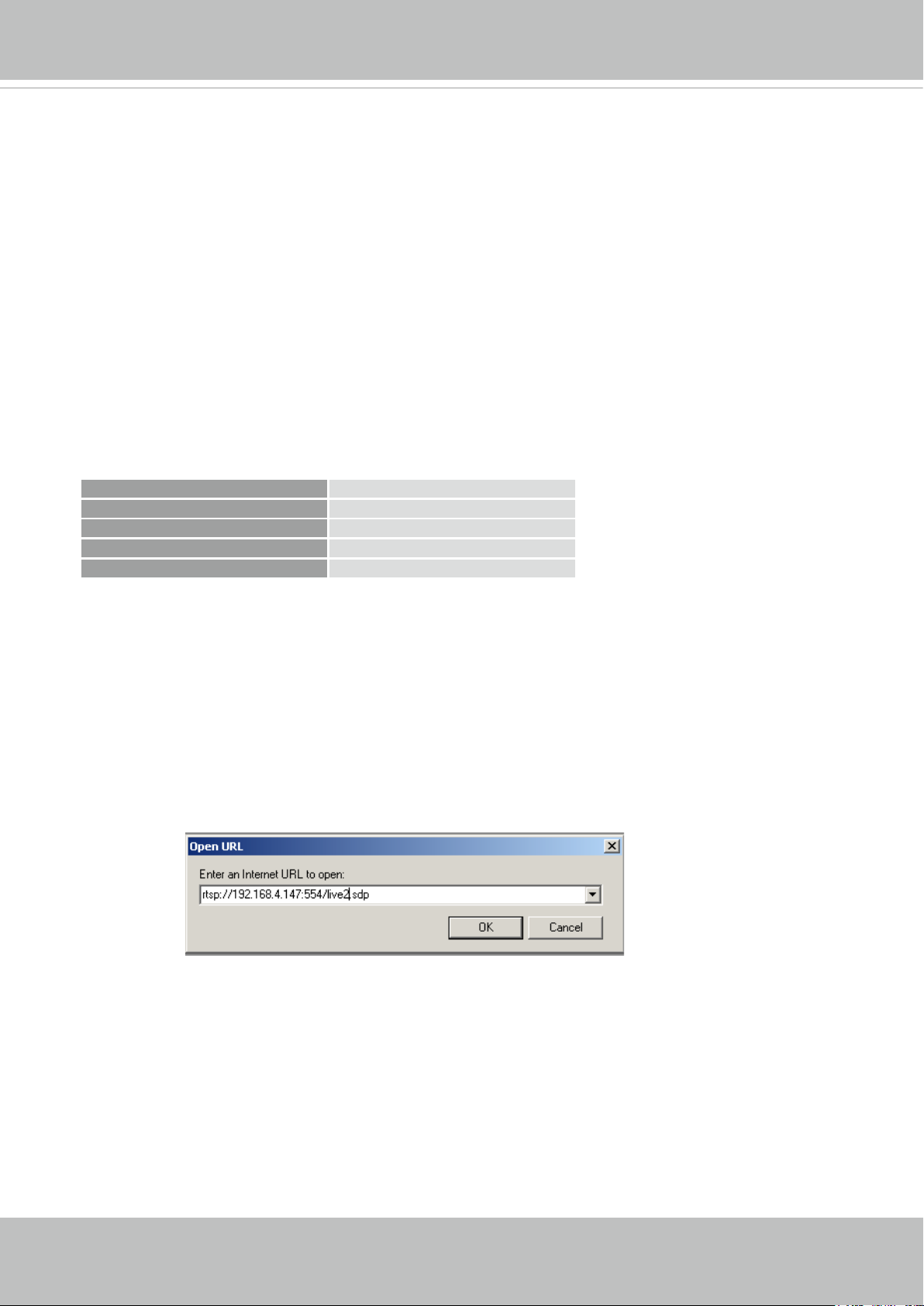
1. Launch the RTSP player.
mpegable Player
2. Choose File > Open URL. A URL dialog box will pop up.
3. The address format is rtsp://<ip address>:<rtsp port>/<RTSP streaming access name for
pvPlayer
stream1 or stream2>
As most ISPs and players only allow RTSP streaming through port number 554, please set the
RTSP port to 554. For more information, please refer to RTSP Streaming on page 59.
For example:
rtsp://192.168.5.151:554/live.sdp
4. The live video will be displayed in your player.
For more information on how to configure the RTSP access name, please refer to RTSP
Streaming on page 59 for details.
Video 16:38:01 2012/01/25
User's Manual - 19
Page 20
VIVOTEK
Video quality (Constant bit rate) 40kbps
Using 3GPP-compatible Mobile Devices
To view the streaming media through 3GPP-compatible mobile devices, make sure the Network
Camera can be accessed over the Internet. For more information on how to set up the Network
Camera over the Internet, please refer to Setup the Network Camera over the Internet on page 9.
To utilize this feature, please check the following settings on your Network Camera:
1. Because most players on 3GPP mobile phones do not support RTSP authentication, make
sure the authentication mode of RTSP streaming is set to disable.
For more information, please refer to RTSP Streaming on page 59.
2. As the the bandwidth on 3G networks is limited, you will not be able to use a large video size.
Please set the video streaming parameters as listed below.
For more information, please refer to Stream settings on page 47.
Video Mode MPEG-4
Frame size 176 x 144
Maximum frame rate 5 fps
Intra frame period 1S
3. As most ISPs and players only allow RTSP streaming through port number 554, please set
the RTSP port to 554. For more information, please refer to RTSP Streaming on page 59.
4. Launch the player on the 3GPP-compatible mobile devices (e.g., Quick Time).
5. Type the following URL commands into the player.
The address format is rtsp://<public ip address of your camera>:<rtsp port>/<RTSP streaming
access name for stream # with small frame size and frame rate>.
For example:
You can configure Stream #2 into the suggested stream settings as listed above for live
viewing on a mobile device.
20 - User's Manual
Page 21
VIVOTEK
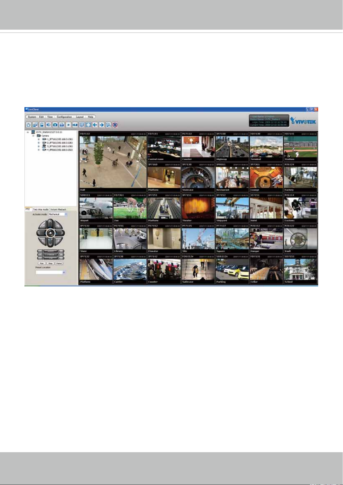
Using VIVOTEK Recording Software
The product software CD also contains an ST7501 recording software, allowing simultaneous
monitoring and video recording for multiple Network Cameras. Please install the recording
software; then launch the program to add the Network Camera to the Channel list. For detailed
information about how to use the recording software, please refer to the user’s manual of the
software or download it from http://www.vivotek.com.
User's Manual - 21
Page 22
VIVOTEK
VIVOTEK INC.
Logo
Live View Window
Camera Control
Area
Configuration
Area
Host Name
Resize Buttons
Hide Button
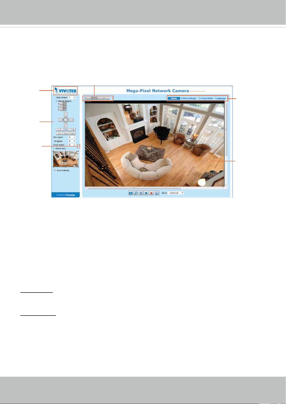
Main Page
This chapter explains the layout of the main page. It is composed of the following sections:
VIVOTEK INC. Logo, Host Name, Camera Control Area, Configuration Area, Menu, and Live
Video Window.
VIVOTEK INC. Logo
Click this logo to visit the VIVOTEK website.
Host Name
The host name can be customized to t your needs. For more information, please refer to System on page 30.
Camera Control Area
Video Stream: This Network Camera supports multiple streams (stream 1 ~ 4) simultaneously. You can
select one of them for live viewing. For more information about multiple streams, please refer to page 47
for detailed information.
Manual Trigger: Click to enable/disable an event trigger manually. Please congure an event setting on
Application page before you enable this function. A total of 3 event settings can be congured. For more
information about event setting, please refer to page 81. If you want to hide this item on the homepage,
please go to Conguration> System > Homepage Layout > General settings > Customized button
to deselect “show manual trigger button”.
22 - User's Manual
Page 23
VIVOTEK
Conguration Area
Client Settings: Click this button to access the client setting page. For more information, please refer to
Client Settings on page 27.
Conguration: Click this button to access the conguration page of the Network Camera. It is suggested
that a password be applied to the Network Camera so that only the administrator can configure the
Network Camera. For more information, please refer to Conguration on page 29.
Language: Click this button to choose a language for the user interface. Language options are available
in: English, Deutsch, Español, Français, Italiano,
日本語
, Português,
簡体中文
, and
繁體中文
. Please
note that you can also change a language on the Conguration page; please refer to page 29.
Hide Button
You can click the hide button to hide the control panel or display the control panel.
Resize Buttons
:
Click the Auto button, the video cell will resize automatically to t the monitor/browser window.
Click 100% is to display the original homepage size.
Click 50% is to resize the homepage to 50% of its original size.
Click 25% is to resize the homepage to 25% of its original size.
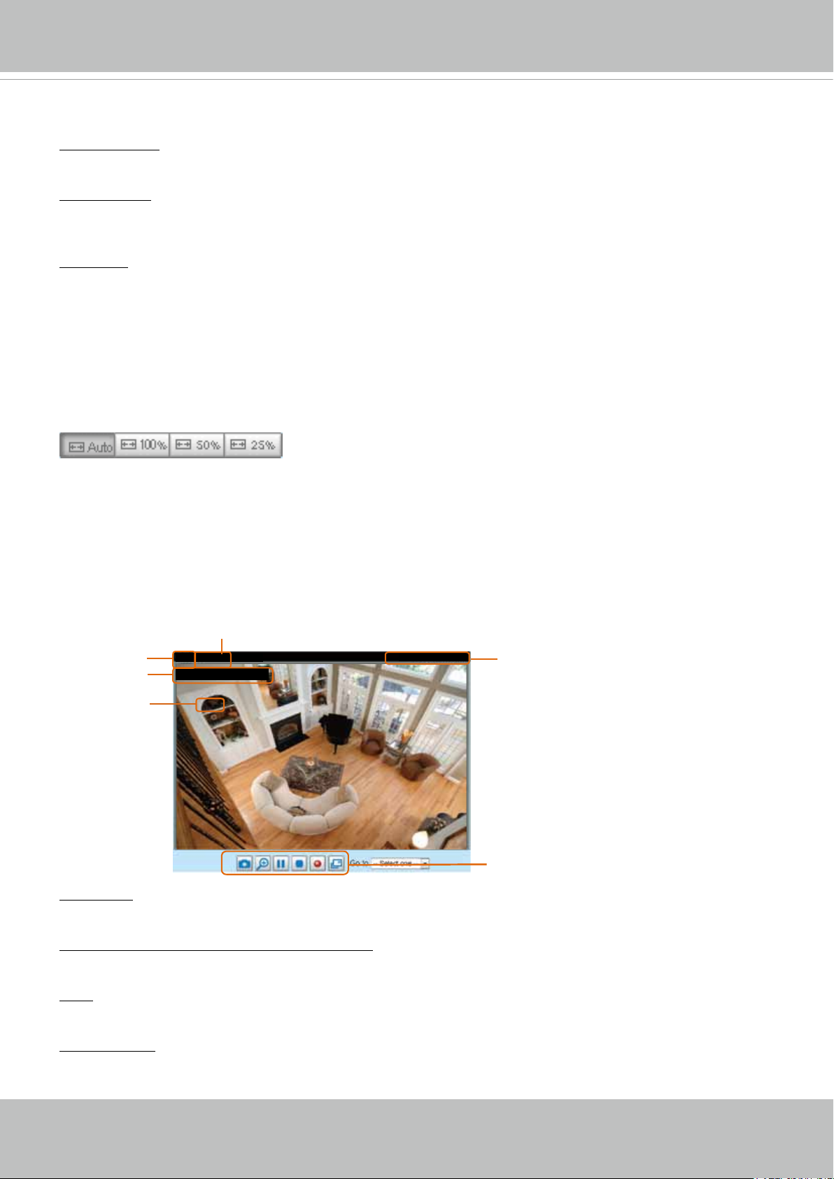
Live Video Window
■ The following window is displayed when the video mode is set to H.264 / MPEG-4:
H.264 / MPEG-4 Protocol and Media Options
Video Title
Title and Time
Zoom Indicator
Video (TPC-AV)
Video 17:08:56 2011/06/25
x4.0
Video Title: The video title can be congured. For more information, please refer to Video Settings on
page 41.
H.264 / MPEG-4 Protocol and Media Options: The transmission protocol and media options for H.264 /
MPEG-4 video streaming. For further conguration, please refer to Client Settings on page 27.
2012/06/08 17:08:56
Time
Video and Audio Control Buttons
Time: Display the current time. For further conguration, please refer to Media > Image > Genral settings
on page 41.
Title and Time: The video title and time can be stamped on the streaming video. For further conguration,
please refer to Media > Image > General settings on page 42.
User's Manual - 23
Page 24
VIVOTEK
PTZ Panel: This Network Camera supports “digital“ (e-PTZ) pan/tilt/zoom control, which allows roaming
a smaller view frame within a large view frame. Please refer to PTZ settiings on page 78 for detailed
information.
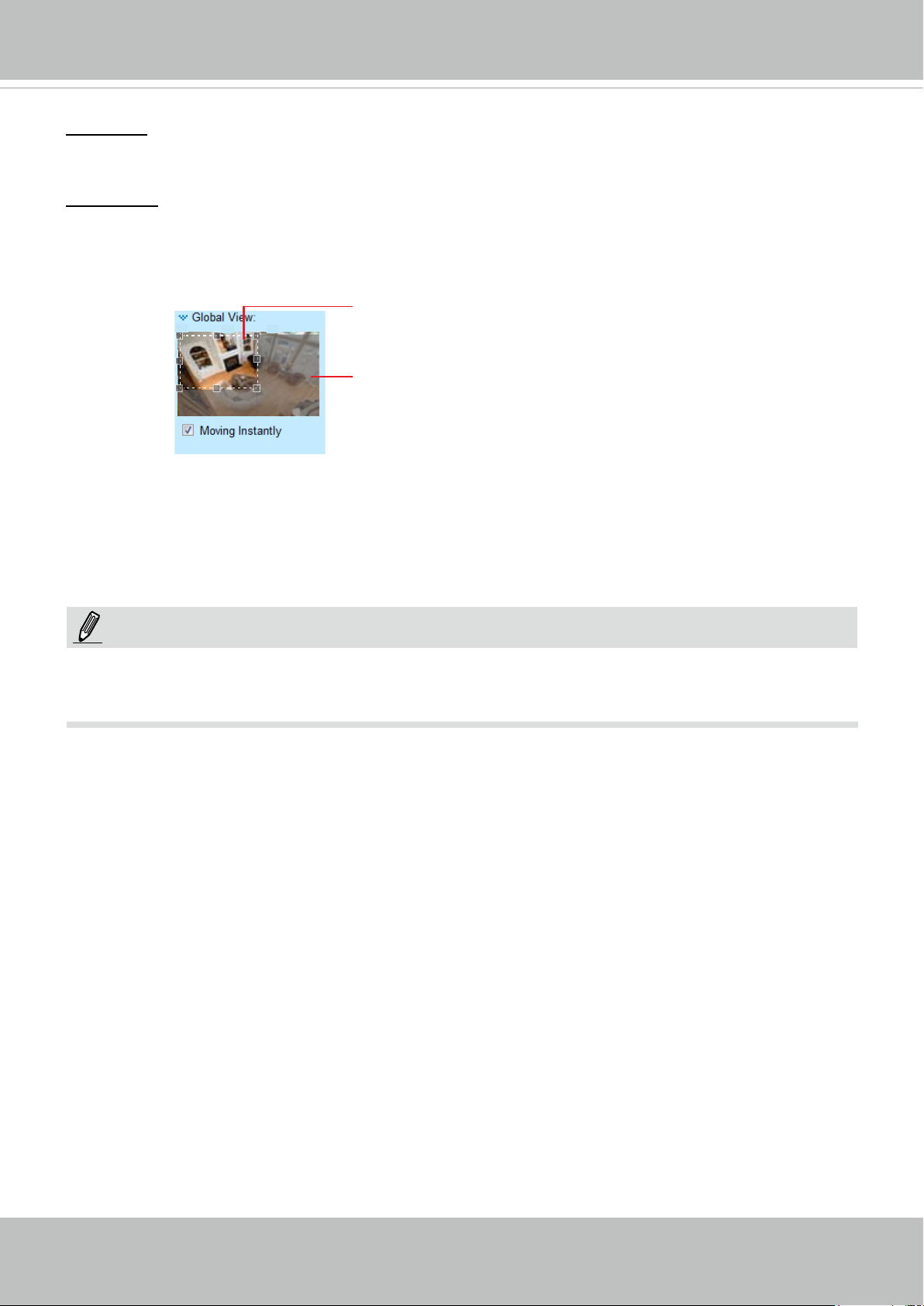
Global View: Click on this item to display the Global View window. The Global View window contains a
full view image (the largest frame size of the captured video) and a oating frame (the viewing region of
the current video stream). The oating frame allows users to control the e-PTZ function (Electronic Pan/
Tilt/Zoom). For more information about e-PTZ operation, please refer to E-PTZ Operation on page 78.
For more information about how to set up the viewing region of the current video stream, please refer to
page 78.
The viewing region of
the current video
stream
The largest frame size
NOTE:
For a megapixel camera, it is recommended to use monitors of the 24" size or larger,
and are capable of 1600x1200 or better resolutions.
24 - User's Manual
Page 25
VIVOTEK
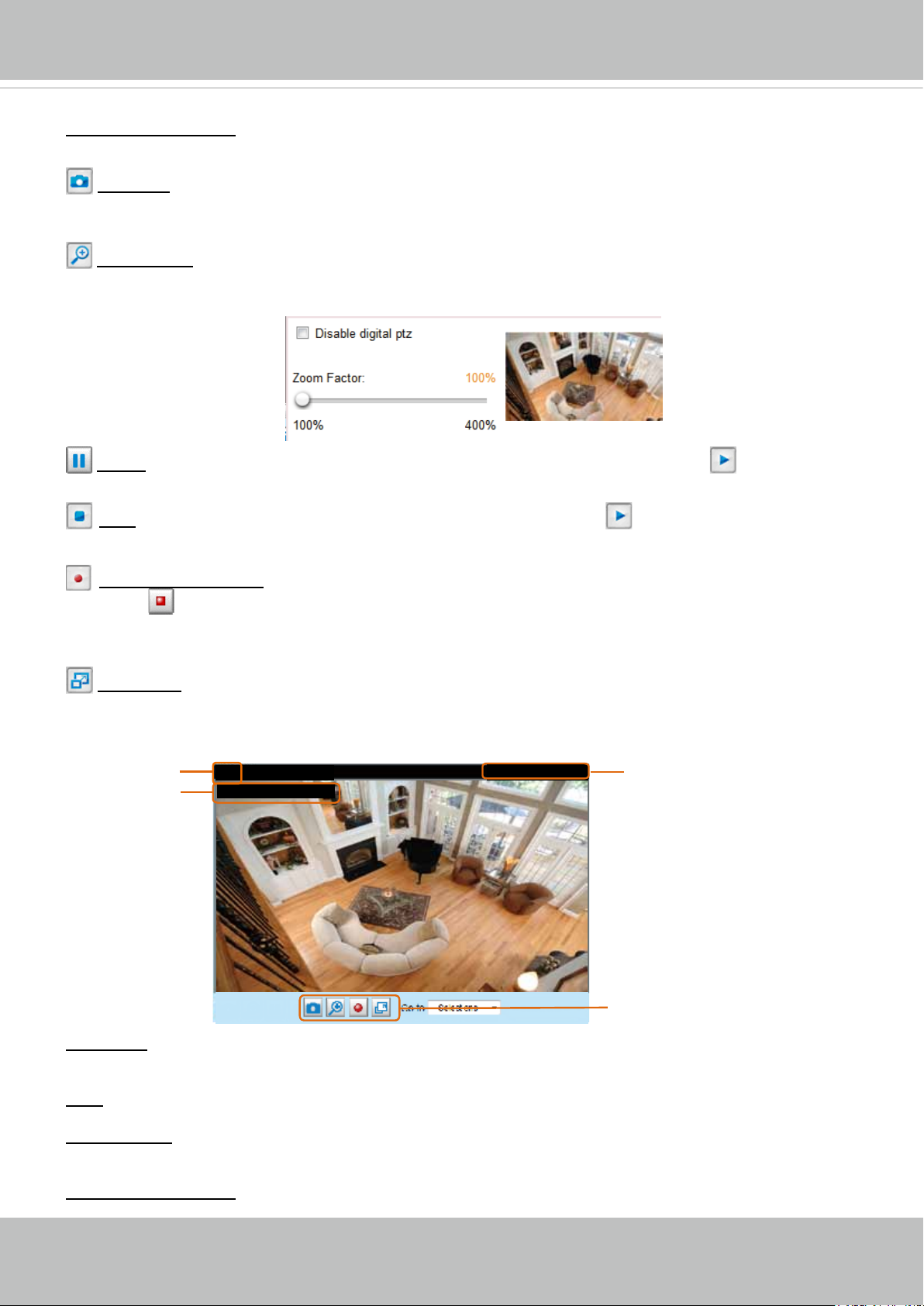
Video Control Buttons: Depending on the Network Camera model and Network Camera conguration,
some buttons may not be available.
Snapshot: Click this button to capture and save still images. The captured images will be displayed
in a pop-up window. Right-click the image and choose Save Picture As to save it in JPEG (*.jpg) or BMP
(*.bmp) format.
Digital Zoom: Click and uncheck “Disable digital zoom” to enable the zoom operation. The navigation
screen indicates the part of the image being magnied. To control the zoom level, drag the slider bar. To
move to a different area you want to magnify, drag the navigation screen.
Pause: Pause the transmission of the streaming media. The button becomes the Resume button
after clicking the Pause button.
Stop: Stop the transmission of the streaming media. Click the Resume button to continue
transmission.
Start MP4 Recording: Click this button to record video clips in MP4 file format to your computer.
Press the Stop MP4 Recording button to end recording. When you exit the web browser, video
recording stops accordingly. To specify the storage destination and le name, please refer to MP4 Saving
Options on page 28 for details.
Full Screen: Click this button to switch to full screen mode. Press the “Esc” key to switch back to normal
mode.
■ The following window is displayed when the video mode is set to MJPEG:
Video Title
Title and Time
Video (HTTP-V)
Video 17:08:56 2011/06/25
2011/02/25 17:08:56
Time
Video Control Buttons
Video Title: The video title can be congured. For more information, please refer to Media > Image on
page 42.
Time: Display the current time. For more information, please refer to Media > Image on page 42.
Title and Time: Video title and time can be stamped on the streaming video. For more information, please
refer to Media > Image on page 42
.
Video Control Buttons: Depending on the Network Camera model and Network Camera conguration,
User's Manual - 25
Page 26
VIVOTEK
some buttons may not be available.
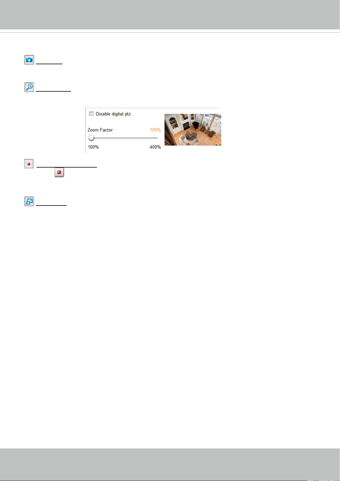
Snapshot: Click this button to capture and save still images. The captured images will be displayed
in a pop-up window. Right-click the image and choose Save Picture As to save it in JPEG (*.jpg) or BMP
(*.bmp) format.
Digital Zoom: Click and uncheck “Disable digital zoom” to enable the zoom operation. The navigation
screen indicates the part of the image being magnied. To control the zoom level, drag the slider bar. To
move to a different area you want to magnify, drag the navigation screen.
Start MP4 Recording: Click this button to record video clips in MP4 file format to your computer.
Press the Stop MP4 Recording button to end recording. When you exit the web browser, video
recording stops accordingly. To specify the storage destination and le name, please refer to MP4 Saving
Options on page 28 for details.
Full Screen: Click this button to switch to full screen mode. Press the “Esc” key to switch back to normal
mode.
26 - User's Manual
Page 27
VIVOTEK
Client Settings
This chapter explains how to select the stream transmission mode and saving options on the
local computer. When completed with the settings on this page, click Save on the page bottom
to enable the settings.
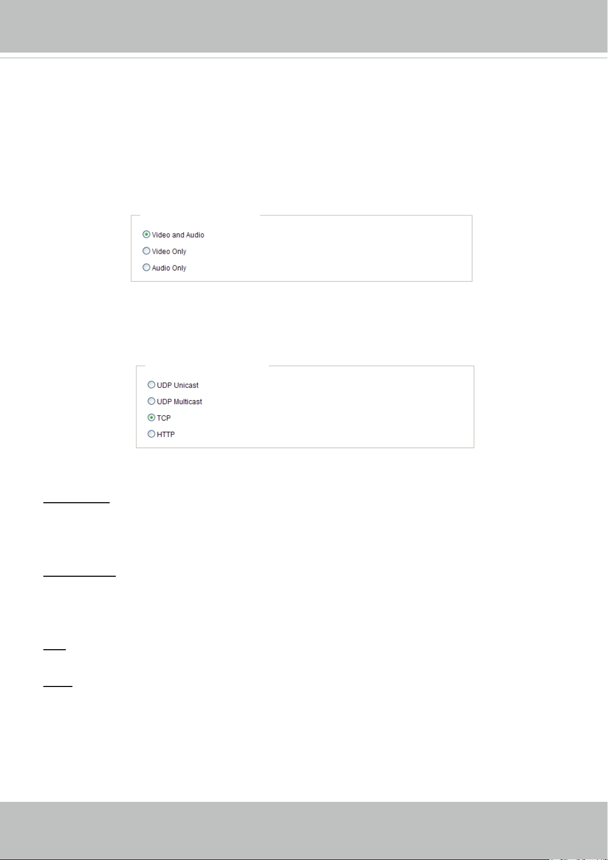
H.264 / MPEG-4 Media Options
H.264/MPEG-4 Media Options
Select to stream video or audio data or both. This is enabled only when the video mode is set to H.264 or
MPEG-4.
H.264 / MPEG-4 Protocol Options
H.264/MPEG-4 Protocol Options
Depending on your network environment, there are four transmission modes of H.264 or MPEG-4
streaming:
UDP unicast: This protocol allows for more real-time audio and video streams. However, network
packets may be lost due to network burst trafc and images may be broken. Activate UDP connection
when occasions require time-sensitive responses and the video quality is less important. Note that each
unicast client connecting to the server takes up additional bandwidth and the Network Camera allows up
to ten simultaneous accesses.
UDP multicast: This protocol allows multicast-enabled routers to forward network packets to all clients
requesting streaming media. This helps to reduce the network transmission load of the Network Camera
while serving multiple clients at the same time. Note that to utilize this feature, the Network Camera must
be configured to enable multicast streaming at the same time. For more information, please refer to
RTSP Streaming on page 59.
TCP: This protocol guarantees the complete delivery of streaming data and thus provides better video
quality. The downside of this protocol is that its real-time effect is not as good as that of the UDP protocol.
HTTP: This protocol allows the same quality as TCP protocol without needing to open specic ports for
streaming under some network environments. Users inside a firewall can utilize this protocol to allow
streaming data through.
User's Manual - 27
Page 28
VIVOTEK
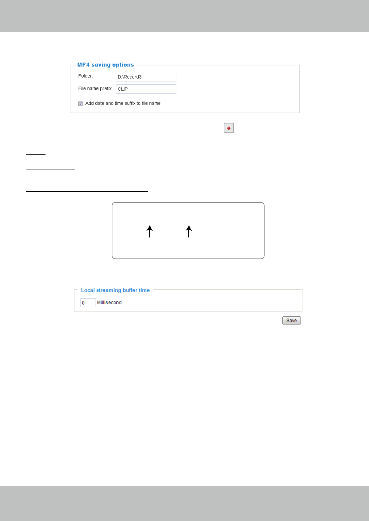
MP4 Saving Options
Users can record live video as they are watching it by clicking Start MP4 Recording on the main
page. Here, you can specify the storage destination and le name.
Folder: Specify a storage destination for the recorded video les. The location can be changed.
File name prex: Enter the text that will be appended to the front of the video le name. A specied folder
will be automatically created on your local hard disk.
Add date and time sufx to the le name: Select this option to append the date and time to the end of the
le name.
CLIP_20110628-180853
File name prefix
Date and time suffix
The format is: YYYYMMDD_HHMMSS
Local Streaming Buffer Time
Chances are you may encounter unsteady bandwidth during operation, the live streaming may lag and
not be very smoothly. If you enable this option, the live streaming will be stored on the camera’s buffer
for a few seconds before being played on the live viewing window. This will help you see the streaming
more smoothly. If you enter 3000 Millisecond, the streaming will delay for 3 seconds.
28 - User's Manual
Page 29
VIVOTEK
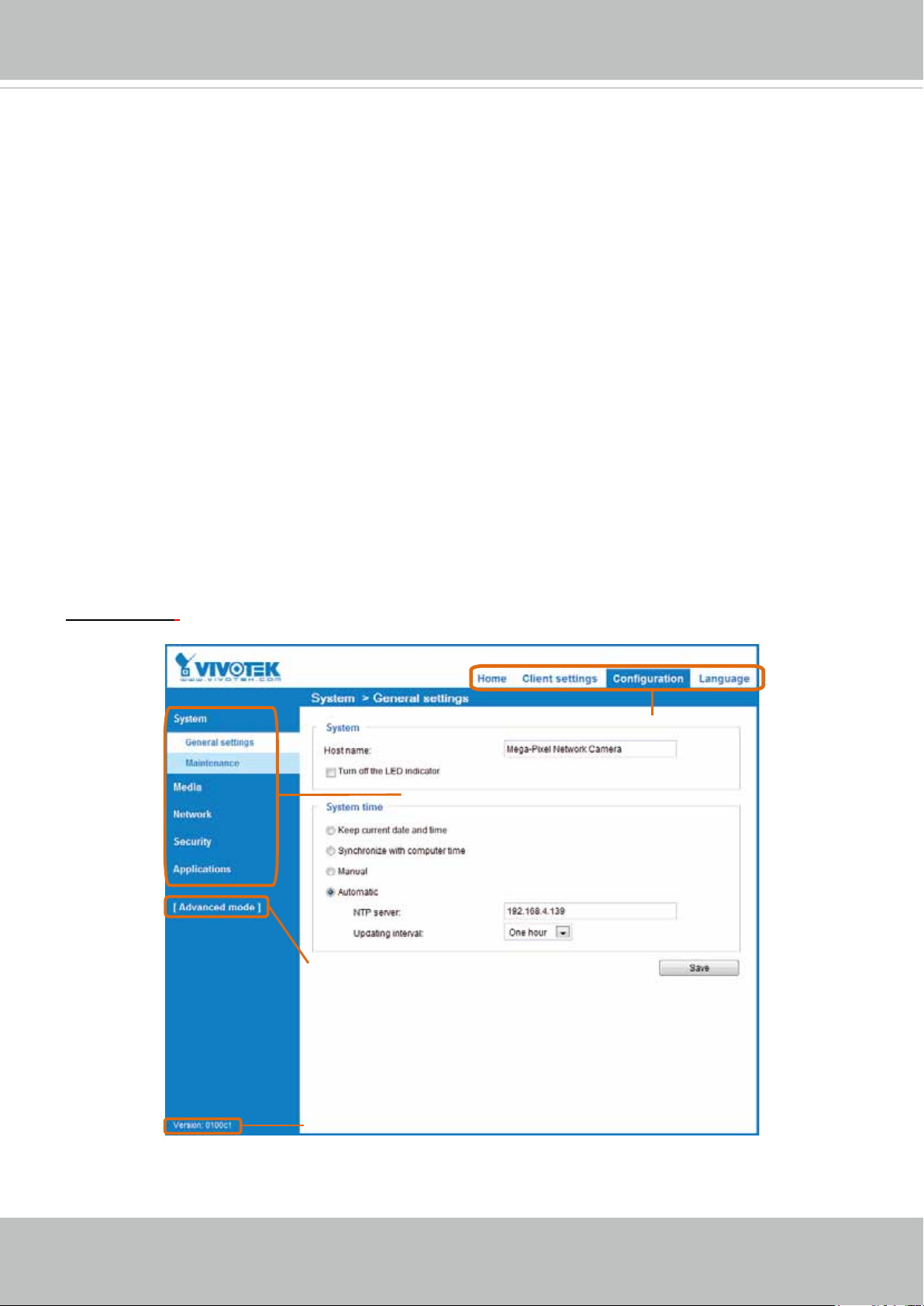
Conguration
Click Configuration on the main page to enter the camera setting pages. Note that only
Administrators can access the conguration page.
VIVOTEK offers an easy-to-use user interface that helps you set up your network camera with
minimal effort. To simplify the setting procedure, two types of user interfaces are available:
Advanced Mode for professional users and Basic Mode for entry-level users. Some advanced
functions (PTZ/ Event/ Recording/ Local storage) are not displayed in Basic Mode.
If you want to set up advanced functions, please click [Advanced Mode] on the bottom of the
conguration list to quickly switch to Advanced Mode.
In order to simplify the user interface, the detailed information will be hidden unless you click on
the function item. When you click on the rst sub-item, the detailed information for the rst sub-
item will be displayed; when you click on the second sub-item, the detailed information for the
second sub-item will be displayed and that of the rst sub-item will be hidden.
The following is the interface of the Basic Mode and the Advanced Mode:
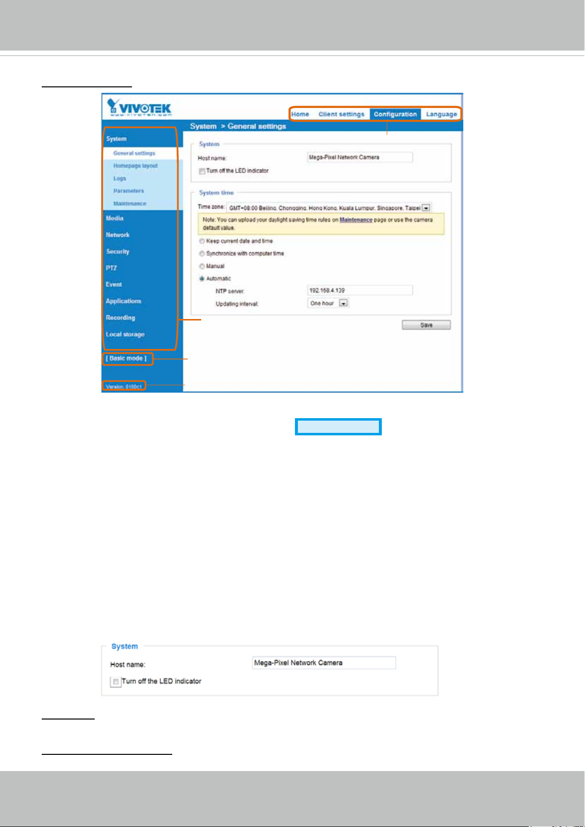
Basic Mode
Navigation Area
Configuration List
Click to switch to Advanced Mode
Firmware Version
User's Manual - 29
Page 30
VIVOTEK
Advanced Mode
Navigation Area
Configuration List
Click to switch to Basic Mode
Firmware Version
Each function on the conguration list will be explained in the following sections. Those functions that are
displayed only in Advanced Mode are marked with
Advanced Mode
. If you want to set up advanced
functions, please click [Advanced Mode] on the bottom of the conguration list to quickly switch over.
Navigation Area provides an instant switch among Home page (the monitoring page for live viewing),
Client settings, Conguration page, and multi-language selection.
System > General settings
This section explains how to congure the basic settings for the Network Camera, such as the
host name and system time. It is composed of the following two columns: System, and System
Time. When finished with the settings on this page, click Save at the bottom of the page to
enable the settings.
System
Host name: Enter a desired name for the Network Camera. The text will be displayed at the top of the
main page, and also on the view cell of ST7501 and VAST management software.
Turn off the LED indicators: If you do not want others to notice the network camera is in operation, you
can select this option to turn off the LED indicators.
30 - User's Manual
Page 31

VIVOTEK
System time
Keep current date and time: Select this option to preserve the current date and time of the Network
Camera. The Network Camera’s internal real-time clock maintains the date and time even when the
power of the system is turned off.
Synchronize with computer time: Select this option to synchronize the date and time of the Network
Camera with the local computer. The read-only date and time of the PC is displayed as updated.
Manual: The administrator can enter the date and time manually. Note that the date and time format are
[yyyy/mm/dd] and [hh:mm:ss].
Automatic: The Network Time Protocol is a protocol which synchronizes computer clocks by periodically
querying an NTP Server.
NTP server: Assign the IP address or domain name of the time-server. Leaving the text box blank
connects the Network Camera to the default time servers.
Update interval: Select to update the time using the NTP server on an hourly, daily, weekly, or monthly
basis.
Time zone
Advanced Mode
: Select the appropriate time zone from the list. If you want to upload
Daylight Savings Time rules, please refer to System > Maintenance > Import/ Export les on page 38
for details.
User's Manual - 31
Page 32

VIVOTEK
System > Homepage layout
Advanced Mode
This section explains how to set up your own customized homepage layout.
General settings
This column shows the settings of your hompage layout. You can manually select the background and
font colors in Theme Options (the second tab on this page). The settings will be displayed automatically
in this Preview eld. The following shows the homepage using the default settings:
■ Hide Powered by VIVOTEK: If you check this item, it will be removed from the homepage.
Logo graph
Here you can change the logo that is placed at the top of your homepage.
Follow the steps below to upload a new logo:
1. Click Custom and the Browse eld will appear.
2. Select a logo from your les.
3. Click Upload to replace the existing logo with a new one.
4. Enter a website link if necessary.
5. Click Save to enable the settings.
Customized button
If you want to hide manual trigger buttons on the homepage, please uncheck this item. This item is
checked by default.
32 - User's Manual
Page 33

VIVOTEK
Theme Options
Here you can change the color of your homepage layout. There are three types of preset patterns for you
to choose from. The new layout will simultaneously appear in the Preview led. Click Save to enable the
settings.
Font Color of the
Video Title
Font Color of
the Configuration Area
Background Color of the
Control Area
Background Color of the
Configuration Area
Font Color
Background Color of
the Video Area
Frame Color
Preset patterns
User's Manual - 33
Page 34

VIVOTEK
■ Follow the steps below to set up the customed homepage:
1. Click Custom on the left column.
2. Click the eld where you want to change the color on the right column.
Custom
Pattern
3. The palette window will pop up as shown below.
Color Selector
2
1
4
4. Drag the slider bar and click on the left square to select a desired color.
5. The selected color will be displayed in the corresponding elds and in the Preview column.
6. Click Save to enable the settings.
3
34 - User's Manual
Page 35

VIVOTEK
System > Logs
Advanced Mode
This section explains how to congure the Network Camera to send the system log to a remote
server as backup.
Log server settings
Follow the steps below to set up the remote log:
1. Select Enable remote log.
2. In the IP address text box, enter the IP address of the remote server.
2. In the port text box, enter the port number of the remote server.
3. When completed, click Save to enable the setting.
You can congure the Network Camera to send the system log le to a remote server as a log backup.
Before utilizing this feature, it is suggested that the user install a log-recording tool to receive system log
messages from the Network Camera. An example is Kiwi Syslog Daemon. Visit http://www.kiwisyslog.
com/kiwi-syslog-daemon-overview/.
System log
This column displays the system log in a chronological order. The system log is stored in the Network
Camera’s buffer area and will be overwritten when reaching a certain limit.
User's Manual - 35
Page 36

VIVOTEK
Access log
Access log displays the access time and IP address of all viewers (including operators and
administrators) in a chronological order. The access log is stored in the Network Camera’s buffer
area and will be overwritten when the number of entries reaches an upper threshold.
System > Parameters
Advanced Mode
The View Parameters page lists the entire system’s parameters. If you need technical
assistance, please provide the information listed on this page.
36 - User's Manual
Page 37

VIVOTEK
System > Maintenance
This chapter explains how to restore the Network Camera to factory default, upgrade rmware
version, etc.
General settings > Upgrade rmware
This feature allows you to upgrade the firmware of your Network Camera. It takes a few minutes to
complete the process.
Note: Do not power off the Network Camera during the upgrade!
Follow the steps below to upgrade the rmware:
1. Download the latest rmware le from the VIVOTEK website. The le is in .pkg le format.
2. Click Browse… and specify the rmware le.
3. Click Upgrade. The Network Camera starts to upgrade and will reboot automatically when the upgrade
completes.
If the upgrade is successful, you will see “Reboot system now!! This connection will close”. After that, reaccess the Network Camera.
The following message is displayed when the upgrade has succeeded.
Reboot system now!!
This connection will close.
The following message is displayed when you have selected an incorrect rmware le.
Starting firmware upgrade...
Do not power down the server during the upgrade.
The server will restart automatically after the upgrade is
completed.
This will take about 1 - 5 minutes.
Wrong PKG file format
Unpack fail
General settings > Reboot
This feature allows you to reboot the Network Camera, which takes about one minute to complete. When
completed, the live video page will be displayed in your browser. The following message will be displayed
during the reboot process.
If the connection fails after rebooting, manually enter the IP address of the Network Camera in the
address eld to resume the connection.
User's Manual - 37
Page 38

VIVOTEK
General settings > Restore
This feature allows you to restore the Network Camera to factory default settings.
Network: Select this option to retain the Network Type settings (please refer to Network Type on page
52).
Daylight Saving Time: Select this option to retain the Daylight Saving Time settings (please refer to
Import/Export les below on this page).
Custom Language: Select this option to retain the Custom Language settings.
If none of the options is selected, all settings will be restored to factory default. The following message is
displayed during the restoring process.
Import/Export les
Advanced Mode
This feature allows you to Export / Update daylight saving time rules, custom language le, conguration
le, and server status report.
Export daylight saving time conguration le: Click to set the start and end time of DST (Daylight Saving).
Follow the steps below to export:
1. In the Export les column, click Export to export the daylight saving time conguration le from the
Network Camera.
2. A le download dialog will pop up as shown below. Click Open to review the XML le or click Save to
store the le for editing.
38 - User's Manual
Page 39

VIVOTEK
3. Open the le with Microsoft® Notepad and locate your time zone; set the start and end time of DST.
When completed, save the le.
In the example below, DST begins each year at 2:00 a.m. on the second Sunday in March and ends at
2:00 a.m. on the rst Sunday in November.
Update daylight saving time rules: Click Browse… and specify the XML le to update.
If the incorrect date and time are assigned, you will see the following warning message when uploading
the le to the Network Camera.
User's Manual - 39
Page 40

VIVOTEK
The following message is displayed when attempting to upload an incorrect le format.
Export language file: Click to export language strings. VIVOTEK provides nine languages: English,
Deutsch, Español, Français, Italiano,
日本語,
Português,
簡体中文
, and
繁體中文
.
Update custom language le: Click Browse… and specify your own custom language le to upload.
Export conguration le: Click to export all parameters for the device and user-dened scripts.
Update conguration le: Click Browse… to update a conguration le. Please note that the model and
rmware version of the device should be the same as the conguration le. If you have set up a xed IP
or other special settings for your device, it is not suggested to update a conguration le.
Export server staus report: Click to export the current server status report, such as time, logs,
parameters, process status, memory status, le system status, network status, kernel message ... and so
on.
40 - User's Manual
Page 41

VIVOTEK
Media > Image
Advanced Mode
This section explains how to configure the image settings of the Network Camera. It is
composed of the following four columns: General settings, Picture settings, Exposure, and
Privacy mask.
General settings
Video title
Show_timestamp_and video_title_in_video_and_snapshots: Enter a name that will be displayed on
the title bar of the live video as the picture shown below.
Video Title
Title and Time
Video 17:08:56 2010/11/25
2012/06/09 17:08:56
Color: Select to display color or black/white video streams.
Power line frequency: Set the power line frequency consistent with local utility settings to eliminate
image flickering associated with fluorescent lights. Note that after the power line frequency is
changed, you must disconnect and reconnect the power cord of the Network Camera in order for
the new setting to take effect.
Video orientation: Flip - vertically reect the display of the live video; Mirror - horizontally reect the
display of the live video. Select both options if the Network Camera is installed upside-down (e.g.,
on the ceiling) to correct the image orientation. Please note that if you have preset locations, those
locations will be cleared after a change in ip/mirror setting.
User's Manual - 41
Page 42

VIVOTEK
Image settings
On this page, you can tune the White balance and Image adjustment settings.
Sensor Setting 1:
For normal situations
Sensor Setting 2:
For special situations
White balance: Adjust the value for the best color temperature.
■ You may follow the steps below to adjust the white balance to the best color temperature.
1. Place a sheet of paper of white or cooler-color temperature paper, such as blue, in front of the
lens, then allow the Network Camera to automatically adjust the color temperature.
2. Click the On button to Fix current value and conrm the setting while the white balance is being
measured.
■ You may also manually tune the color temperature by pulling the RGain and BGain slide bards.
Image Adjustment
■ Brightness: Adjust the image brightness level, which ranges from -5 to +5.
■ Contrast: Adjust the image contrast level, which ranges from -5 to +5.
■ Saturation: Adjust the image saturation level, which ranges from 0% to 100%.
■ Sharpness:
Adjust the image sharpness level, which ranges from
0% to 100%
.
Note that the Preview button has been cancelled, all changes made to image settings is directly
shown on screen. You can click Restore to recall the original settings without incorporating the
changes. When completed with the settings on this page, click Save to enable the setting. You can
also click on Prole to adjust all settings above in a pop-up window for special lighting conditions.
42 - User's Manual
Page 43

VIVOTEK
Exposure
Advanced Mode
On this page, you can set the Measurement window, Exposure level, Exposure mode, and
Gain control. Detailed configurations will be automatically adjusted since the sensor library will
automatically adjust the value according to the ambient light.
Sensor Setting 1:
For normal situations
Sensor Setting 2:
For special situations
Measurement Window: This function allows users to congure a full-view measurement window or
a cental background compensation window for low light compesation.
■ Full view: Calculate the full range of view and offer appropriate
light compesation.
■ BLC: When selected, a BLC window will appear on screen meaning that the center of the scene
will be taken as a weighed area. This option enables light compensation for images that are too
dark or too bright to recognize; for example, for the dark side of objects that is posed against
bright sunlight.
Exposure control:
■
Exposure level: You can manually set the Exposure level, which ranges from -2.0 to +2.0 (dark to
bright).
Flickerless: Under some circumstances when there is a differnece between the video capture
frequency and local AC power frequency (NTSC or PAL), the mismatch causes color shifts or
ickering images. If the above mismatch occurs, select the Flickerless checkbox, and the range
of Exposure time (the shutter time) will be limited to a range in order to match the AC power
frequency. See the screen capture above.
You can click and drag the pointers on the Exposure time and Gain control slide bars to specify
a range of shutter time and Gain control values within which the camera can automaticallly tune
to a better imaging result. For example, you may prefer a shorter shutter time to better capture
User's Manual - 43
Page 44
VIVOTEK
moving objects, while a faster shutter reduces light and needs to be compensated by electrical
brightness gains.
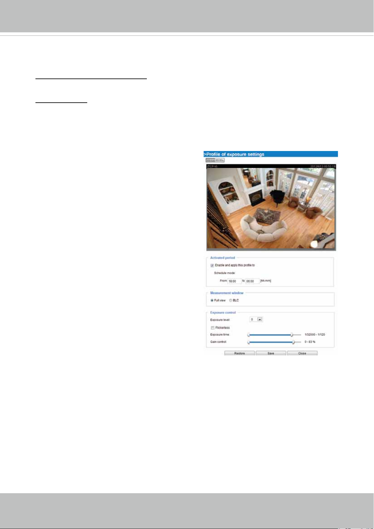
To Congure a Conguration Prole:
Clcik on the Prole button to bring up the conguration window.
Activated period:
Select a period of time during which this configuration will take effect. Please
manually enter a range of time.
You can click Restore to recall the original settings without incorporating the changes. When
completed with the settings on this page, click Save to enable the settings.
Please follow the steps below to setup a prole:
1. Check Enable this prole.
2. Congure a time span.
3. Congure Exposure control settings in the folowing
columns. Please refer to previous dicussions for
detailed information.
4. Click Save to enable the setting and click Close to
exit the page.
44 - User's Manual
Page 45

VIVOTEK
Privacy mask
Advanced Mode
Click Privacy Mask to open the settings page. On this page, you can block out sensitive zones to
address privacy concerns.
2010/12/09 17:08:562010/12/09 17:08:56
■ To set the privacy mask windows, follow the steps below:
1. Click New to add a new window.
2. You can use the mouse cursor to size and drag-drop the window, which is recommended to be
at least twice the size of the object (height and width) you want to cover.
3. Enter a Window Name and click Save to enable the setting.
4. Click on the Enable privacy mask checkbox to enable this function.
►
► If you want to delete the
NOTE:
Up to 5 privacy mask windows can be set up on the same screen.
privacy mask
window, please click the ‘x’ on the upper right corner of
the window.
User's Manual - 45
Page 46

VIVOTEK
Media > Video
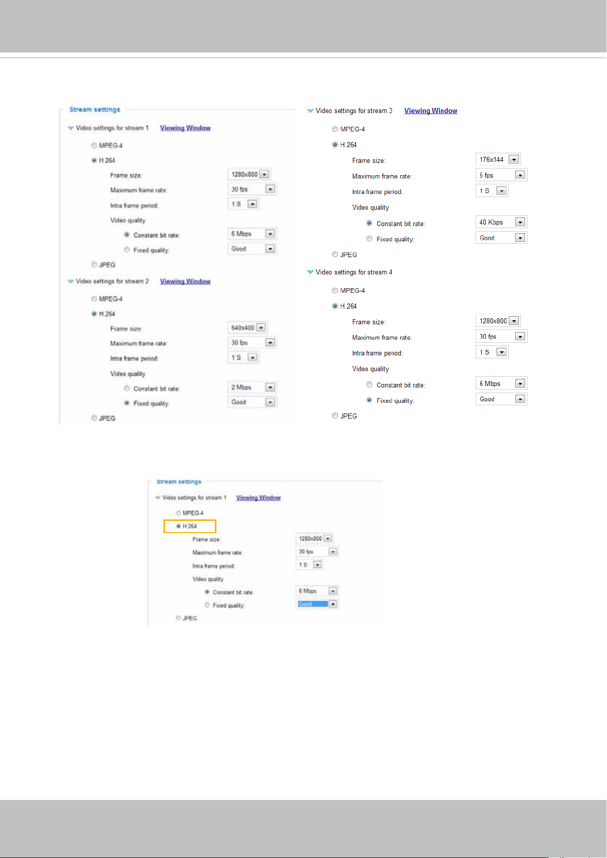
Stream settings
This Network Camera supports multiple streams with frame size ranging from 176 x 144 to 1280 x
800 pixels.
The denition of multiple streams:
■ Stream 1: Users can dene the "Region of Interest" (viewing region) and the "Output Frame Size"
(size of the live view window).
■ Stream 2: The default frame size for Stream 2 is set to a reduced size of 640 x 400 pixels.
■ Stream 3: The default frame size for Stream 3 is set to the minimized 176 x 144 for viewing on
mobile devices.
Advanced Mode
■ Stream 4: Stream 3 does not support the "Region of Interest" conguration.
Click Viewing Window to open the viewing region settings page. On this page, you can set the
Region of Interest and the Output Frame Size for streams #1, #2, and #3.
Please follow the steps below to set up those settings for a stream:
1. Select a stream for which you want to set up the viewing region.
2. Select a Region of Interest from the drop-down list. The floating frame, the same as the
one in the Gloabl View window on the home page, will resize accordingly. If you want to set
up a customized viewing region, you can also resize and drag the oating frame to a desired
position with your mouse.
3. Choose a proper Output Frame Size from the drop-down list according to the size of your
monitoring device.
46 - User's Manual
Page 47

VIVOTEK
Media > Video
NOTE:
► All the items in the “Region of Interest” should not be larger than the “Output Frame Size“
(current maximum resolution).
■ The parameters of the multiple streams:
Region of Interest Output frame size
Stream 1 1280 X 800 ~ 176 x 144 (Selectable) 1280 X 800 ~ 176 x 144 (Selectable)
Stream 2 1280 X 800 ~ 176 x 144 (Selectable) 1280 X 800 ~ 176 x 144 (Selectable)
Stream 3 1280 X 800 ~ 176 x 144 (Selectable) 1280 X 800 ~ 176 x 144 (Selectable)
Stream 4 xed xed
When completed with the settings in the Viewing Window, click Save to enable the settings and
click Close to exit the window. The selected Output Frame Size will immediately be applied to
the Frame size of each video stream. Then you can go back to the home page to test the e-PTZ
function. For more information about the e-PTZ function, please refer to page 78.
X2.1
Region of Interest
(Viewing Region)
Output Frame Size
(Size of the Live View Window)
User's Manual - 47
Page 48
VIVOTEK
Click the stream item to display the detailed information. The maximum frame size will follow your
settings in the above Viewing Window sections.
This Network Camera offers real-time H.264, MPEG-4, and MJPEG compression standards (Triple
Codec) for real-time viewing. If H.264 / MPEG-4 mode is selected, the video is streamed via the
RTSP protocol. There are several parameters for you to adjust the video performance:
■ Frame size
You can set up different video resolution for different viewing devices. For example, set a smaller
frame size and lower bit rate for remote viewing on mobile phones and a larger video size and
a higher bit rate for live viewing on web browsers. Note that a larger frame size takes up more
bandwidth.
■ Maximum frame rate
This limits the maximum refresh frame rate per second. Set the frame rate higher for smoother
video quality and for recognizing moving objects in the eld of view.
If the power line frequency is set to 50Hz, the frame rates are selectable at 1fps, 2fps, 3fps, 5fps,
8fps, 10fps, 15fps, 20fps, 25fps, and 30fps. If the power line frequency is set to 60Hz, the frame
rates are selectable at 1fps, 2fps, 3fps, 5fps, 8fps, 10fps, 15fps, 20fps, 25fps, and 30fps. You can
also select Customize and manually enter a value.
48 - User's Manual
Page 49

VIVOTEK
The frame rate will decrease if you select a higher resolution.
■ Intra frame period
Determine how often to plant an I frame. The shorter the duration, the more likely you will get
better video quality, but at the cost of higher network bandwidth consumption. Select the intra
frame period from the following durations: 1/4 second, 1/2 second, 1 second, 2 seconds, 3
seconds, and 4 seconds.
■
Video quality
Constant bit rate:
• Constant bit rate: A complex scene generally produces a larger le size, meaning that
higher bandwidth will be needed for data transmission. The bandwidth utilization is
congurable to match a selected level, resulting in mutable video quality performance.
The bit rates are selectable at the following rates: 20Kbps, 30Kbps, 40Kbps, 50Kbps,
64Kbps, 128Kbps, 256Kbps, 512Kbps, 768Kbps, 1Mbps, 2Mbps, 3Mbps, 4Mbps,
6Mbps, and 8Mbps. You can also select Customize and manually enter a value.
You should speciy the bit rate setting either as an Average restriction or as an Upper
bound threshold. If set to the Average, video bit rate will uctuate around the Target
bit rate setting.
• Fixed quality: On the other hand, if Fixed quality is selected, all frames are
transmitted with the same quality; bandwidth utilization is therefore unpredictable.
The video quality can be adjusted to the following settings: Medium, Standard, Good,
Detailed, and Excellent. You can also select Customize and manually enter a value.
NOTE:
►
Video quality and xed quality refers to the compression rate, so a lower value will produce higher
quality.
►
Converting high-quality video significantly increases the CPU load, and you may encounter
streaming disconnection or video loss while capturing a complicated scene. In the event of
occurance, we suggest you customize a lower video resolution or reduce the frame rate to obtain
smooth video.
User's Manual - 49
Page 50

VIVOTEK
If the JPEG mode is selected, the Network Camera sends consecutive JPEG images to the client,
producing a moving effect similar to a lmstrip. Every single JPEG image transmitted guarantees
the same image quality, which in turn comes at the expense of variable bandwidth usage. Because
the media contents are a combination of JPEG images, no audio data is transmitted to the client.
There are three parameters provided in MJPEG mode to control the video performance:
■ Frame size
You can set up different video resolution for different viewing devices. For example, set a smaller
frame size and lower bit rate for remote viewing on mobile phones and a larger video size and
a higher bit rate for live viewing on web browsers. Note that a larger frame size takes up more
bandwidth.
■ Maximum frame rate
This limits the maximum refresh frame rate per second. Set the frame rate higher for smoother
video quality.
If the power line frequency is set to 50Hz, the frame rates are selectable at 1fps, 2fps, 3fps, 5fps,
8fps, 10fps, 15fps, 20fps, and 25fps. If the power line frequency is set to 60Hz, the frame rates
are selectable at 1fps, 2fps, 3fps, 5fps, 8fps, 10fps, 15fps, 20fps, 25fps, and 30fps. You can also
select Customize and manually enter a value.
■ Video quality
Refer to the previous page setting an average or upper bound threshold for controlling the
bandwidth consumed for transmitting motion jpegs. The conguration method is identical to that
for MPEG4 and H.264.
50 - User's Manual
Page 51

VIVOTEK
Network > General settings
This section explains how to configure a wired network connection for the Network
Camera.
Network Type
LAN
Select this option when the Network Camera is deployed on a local area network (LAN) and is
intended to be accessed by local computers. The default setting for the Network Type is LAN.
Rememer to click Save when you complete the Network setting.
Get IP address automatically: Select this option to obtain an available dynamic IP address assigned
by the DHCP server each time the camera is connected to the LAN.
Use fixed IP address: Select this option to manually assign a static IP address to the Network
Camera.
1. You can make use of VIVOTEK Installation Wizard 2 on the software CD to easily set up the
Network Camera on LAN. Please refer to Software Installation on page 12 for details.
2. Enter the Static IP, Subnet mask, Default router, and Primary DNS provided by your ISP.
Subnet mask: This is used to determine if the destination is in the same subnet. The default value
is “255.255.255.0”.
Default router: This is the gateway used to forward frames to destinations in a different subnet.
Invalid router setting will fail the transmission to destinations in different subnet.
User's Manual - 51
Page 52

VIVOTEK
Primary DNS: The primary domain name server that translates hostnames into IP addresses.
Secondary DNS: Secondary domain name server that serves as a backup to the Primary DNS.
Primary WINS server: The primary WINS server that maintains the database of computer names
and IP addresses.
Secondary WINS server: The secondary WINS server that maintains the database of computer
names and IP addresses.
Enable UPnP presentation: Select this option to enable UPnPTM presentation for your Network
Camera so that whenever a Network Camera is presented to the LAN, shortcuts of connected
Network Cameras will be listed in My Network Places. You can click the shortcut to link to the web
browser. Currently, UPnPTM is supported by Windows XP or later. Note that to utilize this feature,
please make sure the UPnPTM component is installed on your computer.
Mega-pixel Network Camera (192.168.5.151)
Enable UPnP port forwarding: To access the Network Camera from the Internet, select this option
to allow the Network Camera to open ports automatically on the router so that video streams can
be sent out from a LAN. To utilize of this feature, make sure that your router supports UPnPTM and
it is activated.
PPPoE (Point-to-point over Ethernet)
Select this option to congure your Network Camera to make it accessible from anywhere as long
as there is an Internet connection. Note that to utilize this feature, it requires an account provided
by your ISP.
Follow the steps below to acquire your Network Camera’s public IP address.
1. Set up the Network Camera on the LAN.
2. Go to Conguration > Event > Event settings > Add server (please refer to Add server on page
85) to add a new email or FTP server.
3. Go to Conguration > Event > Event settings > Add media (please refer to Add media on page
90).
Select System log so that you will receive the system log in TXT le format which contains the
Network Camera’s public IP address in your email or on the FTP server.
4. Go to Conguration > Network > General settings > Network type. Select PPPoE and enter the
user name and password provided by your ISP. Click Save to enable the setting.
5. The Network Camera will reboot.
6. Disconnect the power to the Network Camera; remove it from the LAN environment.
52 - User's Manual
Page 53

VIVOTEK
NOTE
NOTE:
► If the default ports are already used by other devices connected to the same router, the Network
Camera will select other ports for the Network Camera.
► If UPnPTM is not supported by your router, you will see the following message:
Error: Router does not support UPnP port forwarding.
► Below are steps to enable the UPnPTM user interface on your computer:
Note that you must log on to the computer as a system administrator to install the UPnPTM
components.
1. Go to Start, click Control Panel, then click Add or Remove Programs.
2. In the Add or Remove Programs dialog box, click Add/Remove Windows Components.
3.
In the Windows Components Wizard dialog box, select Networking Services and click
Details.
User's Manual - 53
Page 54

VIVOTEK
4. In the Networking Services dialog box, select Universal Plug and Play and click OK.
5. Click Next in the following window.
6. Click Finish. UPnPTM is enabled.
► How does UPnPTM work?
UPnP
TM
networking technology provides automatic IP configuration and dynamic discovery of
devices added to a network. Services and capabilities offered by networked devices, such as
printing and file sharing, are available among each other without the need for cumbersome
network conguration. In the case of Network Cameras, you will see Network Camera shortcuts
under My Network Places.
► Enabling UPnP port forwarding allows the Network Camera to open a secondary HTTP port on
the router-not HTTP port-meaning that you have to add the secondary HTTP port number to the
Network Camera’s public address in order to access the Network Camera from the Internet. For
example, when the HTTP port is set to 80 and the secondary HTTP port is set to 8080, refer to
the list below for the Network Camera’s IP address.
From the Internet In LAN
http://203.67.124.123:8080 http://192.168.4.160 or
http://192.168.4.160:8080
► If the PPPoE settings are incorrectly congured or the Internet access is not working, restore
the Network Camera to factory default; please refer to Restore on page 38 for details. After the
Network Camera is reset to factory default, it will be accessible on the LAN.
54 - User's Manual
Page 55

VIVOTEK
Enable IPv6
Select this option and click Save to enable IPv6 settings.
Please note that this only works if your network environment and hardware equipment support
IPv6. The browser should be Microsoft® Internet Explorer 6.5, Mozilla Firefox 3.0 or above.
When IPv6 is enabled, by default, the network camera will listen to router advertisements and be
assigned with a link-local IPv6 address accordingly.
IPv6 Information: Click this button to obtain the IPv6 information as shown below.
If your IPv6 settings are successful, the IPv6 address list will be listed a the pop-up window. The
IPv6 address will be displayed as follows:
Refers to Ethernet
Link-global IPv6 address/network mask
Link-local IPv6 address/network mask
User's Manual - 55
Page 56

VIVOTEK
Please follow the steps below to link to an IPv6 address:
1. Open your web browser.
2. Enter the link-global or link-local IPv6 address in the address bar of your web browser.
3. The format should be:
http://[2001:0c08:2500:0002:0202:d1ff:fe04:65f4]/
IPv6 address
4. Press Enter on the keyboard or click Refresh button to refresh the webpage.
For example:
NOTE:
► If you have a Secondary HTTP port (the default value is 8080), you can also link to the webpage
in the following address format: (Please refer to HTTP streaming on page 58 for detailed
information.)
http://[2001:0c08:2500:0002:0202:d1ff:fe04:65f4]/:8080
IPv6 address
Secondary HTTP port
► If you choose PPPoE as the Network Type, the [PPP0 address] will be displayed in the IPv6
information column as shown below.
Manually setup the IP address: Select this option to manually set up IPv6 settings if your network
environment does not have DHCPv6 server and router advertisements-enabled routers.
If you check this item, the following blanks will be displayed for you to enter the corresponding
information:
56 - User's Manual
Page 57

Port
VIVOTEK
HTTPS port: By default, the HTTPS port is set to 443. It can also be assigned to another port
number between 1025 and 65535.
FTP port: The FTP server allows the user to save recorded video clips. You can utilize VIVOTEK's
Installation Wizard 2 to upgrade the rmware via FTP server. By default, the FTP port is set to 21.
It also can be assigned to another port number between 1025 and 65535.
User's Manual - 57
Page 58

VIVOTEK
Network > Streaming protocols
Advanced Mode
HTTP streaming
To utilize HTTP authentication, make sure that your have set a password for the Network Camera
rst; please refer to Security > User account on page 67 for details.
Authentication: Depending on your network security requirements, the Network Camera provides
two types of security settings for an HTTP transaction: basic and digest.
If basic authentication is selected, the password is sent in plain text format and there can be
potential risks of being intercepted. If digest authentication is selected, user credentials are
encrypted using MD5 algorithm and thus provide better protection against unauthorized accesses.
HTTP port / Secondary HTTP port: By default, the HTTP port is set to 80 and the secondary HTTP
port is set to 8080. They can also be assigned to another port number between 1025 and 65535. If
the ports are incorrectly assigned, the following warning messages will be displayed:
To access the Network Camera on the LAN, both the HTTP port and secondary HTTP port can
be used to access the Network Camera. For example, when the HTTP port is set to 80 and the
secondary HTTP port is set to 8080, refer to the list below for the Network Camera’s IP address.
On the LAN
http://192.168.4.160 or
http://192.168.4.160:8080
Access name for stream #1 ~ #5: This Network camera supports multiple streams simultaneously.
The access name is used to differentiate the streaming source. Users can click Media > Video >
Stream settings to set up the video quality of linked streams. For more information about how to
set up the video quality, please refer to Stream settings on page 47.
When using Mozilla Firefox or Netscape to access the Network Camera and the video mode is
set to JPEG, users will receive video comprised of continuous JPEG images. This technology,
known as “server push”, allows the Network Camera to feed live pictures to Mozilla Firefox and
Netscape.
58 - User's Manual
Page 59

URL command -- http://<ip address>:<http port>/<access name for a specic stream>
For example, when the Access name for stream 2 is set to video2.mjpg:
1. Launch Mozilla Firefox or Netscape.
2. Type the above URL command in the address bar. Press Enter.
3. The JPEG images will be displayed in your web browser.
http://192.168.5.151/video2.mjpg
VIVOTEK
NOTE
NOTE:
► Microsoft® Internet Explorer does not support server push technology; therefore, you will not be
able to access the camera using the http://<ip address>:<http port>/<access name for a specic
stream > command.
► Users can only use URL commands to request the stream 5. For more information about URL
commands, please refer to page 108.
RTSP Streaming
To utilize RTSP streaming authentication, make sure that you have set a password for controlling
the access to video stream rst. Please refer to Security > User account on page 67 for details.
User's Manual - 59
Page 60

VIVOTEK
Authentication: Depending on your network security requirements, the Network Camera provides
three types of security settings for streaming via RTSP protocol: disable, basic, and digest.
If basic authentication is selected, the password is sent in plain text format, but there can be
potential risks of it being intercepted. If digest authentication is selected, user credentials are
encrypted using MD5 algorithm, thus providing better protection against unauthorized access.
The availability of the RTSP streaming for the three authentication modes is listed in the following
table:
Disable O O
Basic O O
Digest O X
Quick Time player VLC
Access name for stream #1 ~ #5: This Network camera supports multiple streams simultaneously.
The access name is used to differentiate the streaming source. In this way, streams of different
qualities can sufce different purposes.
If you want to use an RTSP player to access the Network Camera, you have to set the video mode
to H.264 / MPEG-4 and use the following RTSP URL command to request transmission of the
streaming data.
rtsp://<ip address>:<rtsp port>/<access name for a specic stream>
For example, when the access name for stream 1 is set to live.sdp:
1. Launch an RTSP player.
2. Choose File > Open URL. A URL dialog box will pop up.
3. Type the above URL command in the text box.
4. The live video will be displayed in your player as shown
below.
Video 16:38:01 2012/01/25
rtsp://192.168.5.151:554/live.sdp
RTSP port /RTP port for video, audio/ RTCP port for video, audio
■ RTSP (Real-Time Streaming Protocol) controls the delivery of streaming media. By default, the
port number is set to 554.
■ The RTP (Real-time Transport Protocol) is used to deliver video data to the clients. By default,
the RTP port for video is set to 5556 and the RTP port for audio is set to 5558.
■ The RTCP (Real-time Transport Control Protocol) allows the Network Camera to transmit the
data by monitoring the Internet trafc volume. By default, the RTCP port for video is set to 5557
and the RTCP port for audio is set to 5559.
The port numbers can be changed to values between 1025 and 65535. The RTP port must be
an even number and the RTCP port is the RTP port number plus one, and thus is always an odd
number. When the RTP port changes, the RTCP port will change accordingly.
If the RTP ports are incorrectly assigned,
the following warning message will be displayed:
60 - User's Manual
Page 61

VIVOTEK
Multicast settings for stream 1, 2, 3, and 4: Click the items to display the detailed configuration
information. Select the Always multicast option to enable multicast for stream 1 or 2.
Unicast video transmission delivers a stream through point-to-point transmission; multicast, on the
other hand, sends a stream to the multicast group address and allows multiple clients to acquire
the stream at the same time by requesting a copy from the multicast group address. Therefore,
enabling multicast can effectively save Internet bandwith.
The ports can be changed to values between 1025 and 65535. The multicast RTP port must be an
even number and the multicast RTCP port number is the multicast RTP port number plus one, and
thus is always odd. When the multicast RTP port changes, the multicast RTCP port will change
accordingly.
If the multicast RTP video ports are incorrectly assigned, the following warning message will be
displayed:
Multicast TTL [1~255]: The multicast TTL (Time To Live) is the value that tells the router the range
a packet can be forwarded.
User's Manual - 61
Page 62

VIVOTEK
Network > DDNS
This section explains how to congure the dynamic domain name service for the Network
Camera. DDNS is a service that allows your Network Camera, especially when assigned
with a dynamic IP address, to have a xed host and domain name.
DDNS: Dynamic domain name service
Enable DDNS: Select this option to enable the DDNS setting.
Provider: Select a DDNS provider from the provider drop-down list.
VIVOTEK offers Safe100.net, a free dynamic domain name service, to VIVOTEK customers. It
is recommended that you register Safe100.net to access VIVOTEK’s Network Cameras from the
Internet. Additionally, we offer other DDNS providers, such as Dyndns.org(Dynamic), Dyndns.
org(Custom), TZO.com, DHS.org, CustomSafe100, dyn-interfree.it.
Note that before utilizing this function, please apply for a dynamic domain account rst.
■ Safe100.net
1. In the DDNS column, select Safe100.net from the drop-down list. Click I accept after reviewing
the terms of the Service Agreement.
2. In the Register column, ll in the Host name (xxxx.safe100.net), Email, Key, and Conrm Key,
and click Register. After a host name has been successfully created, a success message will
be displayed in the DDNS Registration Result column.
[Register] Successfully Your account information has
been mailed to registered e-mail address
3. Click Copy and all the registered information will automatically be uploaded to the corresponding
elds in the DDNS column at the top of the page as seen in the picture.
62 - User's Manual
Page 63

VIVOTEK
[Register] Successfully Your account information has
been mailed to registered e-mail address
4. Select Enable DDNS and click Save to enable the setting.
■ CustomSafe100
VIVOTEK offers documents to establish a CustomSafe100 DDNS server for distributors and
system integrators. You can use CustomSafe100 to register a dynamic domain name if your
distributor or system integrators offer such services.
1. In the DDNS column, select CustomSafe100 from the drop-down list.
2. In the Register column, ll in the Host name, Email, Key, and Conrm Key; then click Register.
After a host name has been successfully created, you will see a success message in the DDNS
Registration Result column.
3. Click Copy and all for the registered information will be uploaded to the corresponding elds in
the DDNS column.
4. Select Enable DDNS and click Save to enable the setting.
Forget key: Click this button if you have forgotten the key to Safe100.net or CustomSafe100. Your
account information will be sent to your email address.
Refer to the following links to apply for a dynamic domain account when selecting other
DDNS providers:
■ Dyndns.org(Dynamic) / Dyndns.org(Custom): visit http://www.dyndns.com/
■ TZO.com: visit http://www.tzo.com/
■ DHS.org: visit http://www.dhs.org/
■ dyn-interfree.it: visit http://dyn-interfree.it/
User's Manual - 63
Page 64

VIVOTEK
Advanced Mode
Network > QoS (Quality of Service)
Quality of Service refers to a resource reservation control mechanism, which guarantees the quality
to different services on the network. Quality of service guarantees are important if the network
capacity is insufcient, especially for real-time streaming of multimedia applications. Quality can be
dened as, for instance, a maintained level of bit rate, low latency, no packet dropping, etc.
The following are the main benets of a QoS-aware network:
The ability to prioritize trafc and guarantee a certain level of performance to the data ow.
■
The ability to control the amount of bandwidth each application may use, and thus provide higher
■
reliability and stability on the network.
Requirements for QoS
To utilize QoS in a network environment, the following requirements must be met:
All network switches and routers in the network must include support for QoS.
■
The network video devices used in the network must be QoS-enabled.
■
QoS models
CoS (the VLAN 802.1p model)
IEEE802.1p denes a QoS model at OSI Layer 2 (Data Link Layer), which is called CoS, Class of
Service. It adds a 3-bit value to the VLAN MAC header, which indicates the frame priority level from
0 (lowest) to 7 (highest). The priority is set up on the network switches, which then use different
queuing disciplines to forward the packets.
Below is the setting column for CoS. Enter the VLAN ID of your switch (0~4095) and choose the
priority for each application (0~7).
If you assign Video the highest level, the switch will handle video packets rst.
NOTE:
► A VLAN-capable wwitch (802.1p) is required. The web browsing may fail if the CoS setting is
incorrect.
► Class of Service technologies do not guarantee a level of service in terms of bandwidth and
delivery time; they offer a "best-effort." Users can think of CoS as "coarsely-grained" traffic
control and QoS as "nely-grained" trafc control.
► Although CoS is simple to manage, it lacks scalability and does not offer end-to-end guarantees
since it is based on L2 protocol.
64 - User's Manual
Page 65

VIVOTEK
QoS/DSCP (the DiffServ model)
DSCP-ECN denes QoS at Layer 3 (Network Layer). The Differentiated Services (DiffServ) model
is based on packet marking and router queuing disciplines. The marking is done by adding a eld
to the IP header, called the DSCP (Differentiated Services Codepoint). This is a 6-bit field that
provides 64 different class IDs. It gives an indication of how a given packet is to be forwarded,
known as the Per Hop Behavior (PHB). The PHB describes a particular service level in terms of
bandwidth, queueing theory, and dropping (discarding the packet) decisions. Routers at each
network node classify packets according to their DSCP value and give them a particular forwarding
treatment; for example, how much bandwidth to reserve for it.
Below are the configuration options of DSCP (DiffServ Codepoint). Specify the DSCP value for
each application (0~63).
User's Manual - 65
Page 66

VIVOTEK
Network > SNMP
(Simple Network Management Protocol)
Advanced Mode
This section explains how to use the SNMP on the network camera. The Simple Network
Management Protocol is an application layer protocol that facilitates the exchange of
management information between network devices. It helps network administrators to
remotely manage network devices and nd, solve network problems with ease.
■ The SNMP consists of the following three key components:
1. Manager: Network-management station (NMS), a server which executes applications that
monitor and control managed devices.
2. Agent: A network-management software module on a managed device which transfers the status
of managed devices to the NMS.
3. Managed device: A network node on a managed network. For example: routers, switches,
bridges, hubs, computer hosts, printers, IP telephones, network cameras, web server, and
database.
Before conguring SNMP settings on the this page, please enable your NMS rst.
SNMP Conguration
Enable SNMPv1, SNMPv2c
Select this option and enter the names of Read/Write community and Read Only community
according to your NMS settings.
Enable SNMPv3
This option contains cryptographic security, a higher security level, which allows you to set the
Authentication password and the Encryption password.
■ Security name: According to your NMS settings, choose Read/Write or Read Only and enter the
community name.
■ Authentication type: Select MD5 or SHA as the authentication method.
■ Authentication password: Enter the password for authentication (at least 8 characters).
■ Encryption password: Enter a password for encryption (at least 8 characters).
66 - User's Manual
Page 67

VIVOTEK
Security > User Account
This section explains how to enable password protection and create multiple accounts.
Root Password
The administrator account name is “root”, which is permanent and can not be deleted. If you
want to add more accounts in the Manage User column, please apply the password for the “root”
account rst.
1. Type the password identically in both text boxes, then click Save to enable password protection.
2. A window will be prompted for authentication; type the correct user’s name and password in their
respective elds to access the Network Camera.
Privilege Management
PTZ control: You can modify the management privilege for operators or viewers. Select or deselect
the checkboxes, then click Save to enable the settings. If you give Viewers the privilege, Operators
will also have the ability to control the Network Camera through the main page. (Please refer to
Conguration on page 29).
Allow anonymous viewing: If you check this item, any client can access the live stream without
entering a User ID and Password.
Advanced Mode
Account Management
Administrators can create up to 20 user accounts.
1. Input the new user’s name and password.
2. Select the privilege level for the new user account. Click Add to enable the setting.
Access rights are sorted by user privilege (Administrator, Operator, and Viewer). Only
administrators can access the Configuration page. Although operators cannot access the
Conguration page, they can use the URL Commands to get and set the value of parameters. For
more information, please refer to URL Commands of the Network Camera on page 108. Viewers
can only access the main page for live viewing.
Here you also can change a user’s access rights or delete user accounts.
1. Select an existing account to modify.
2. Make necessary changes and click Update or Delete to enable the setting.
User's Manual - 67
Page 68

VIVOTEK
Security > HTTPS
(Hypertext Transfer Protocol over SSL)
Advanced Mode
This section explains how to enable authentication and encrypted communication over
SSL (Secure Socket Layer). It helps protect streaming data transmission over the Internet
on higher security level.
Create and Install Certicate Method
Before using HTTPS for communication with the Network Camera, a Certicate must be created
rst. There are three ways to create and install a certicate:
Create self-signed certificate
1. Select this option from a pull-down menu.
2. In the rst column, select Enable HTTPS secure connection, then select a connection option:
“HTTP & HTTPS” or “HTTPS only”.
3. Click Create certicate to generate a certicate.
4. The Certicate Information will automatically be displayed as shown below. You can click Certi-
cate properties to view detailed information about the certicate.
68 - User's Manual
Page 69

VIVOTEK
https://
5. Click Home to return to the main page. Change the address from “http://” to “https://“ in the ad-
dress bar and press Enter on your keyboard. Some Security Alert dialogs will pop up. Click OK
or Yes to enable HTTPS.
https://192.168.5.151/index.html
User's Manual - 69
Page 70

VIVOTEK
Create certificate and install : Select this option if you want to create a certicate from a
certication authority.
1. Select this option from a method pull-down menu.
2. Click Create certicate to generate the certicate.
3. The following information will appear in a pop-up window after clicking Create. If you see
the following Information bar, click OK and click on the Information bar at the top of the
page to allow pop-ups.
70 - User's Manual
Page 71

VIVOTEK
4. The Certicate Information will automatically be displayed in the third column as shown below.
You can click Property to see detailed information about the certicate.
. Copy the contents of the Certicate request (in PEM format). Use the contents to apply for a
5
3rd-party certication authority such as Symantec VeriSign. Wait for the certicate authority to
issue an SSL certicate; click Browse to search for the issued certicate, and then click Upload
to nish the process.
User's Manual - 71
Page 72

VIVOTEK
NOTE
NOTE:
► How do I cancel the HTTPS settings?
1. Click on the Remove certicate button.
2. If you are currently running a secure connection The webpage will redirect to a non-HTTPS
page automatically.
Enable HTTPS
Check this item to enable HTTPS communication, then select a connection option: "HTTP &
HTTPS" or "HTTPS only". Note that you have to create and install a certicate rst before clicking
the Save button.
72 - User's Manual
Page 73

VIVOTEK
Security > Access List
Advanced Mode
This section explains how to control access permission by verifying the client PC’s IP
address.
General Settings
Maximum number of concurrent streaming connection(s) limited to: Simultaneous live viewing for
1~10 clients (including stream 1 to stream 3). The default value is 10. If you modify the value and
click Save, all current connections will be disconnected and automatically attempt to re-link (IE
Explorer or Quick Time Player).
Connection Management: Click this button to display the connection status window showing a list
of the current connections. For example:
Note that only consoles that are currently displaying live streaming will be listed in the Connection
Management window.
■ IP address: Current connections to the Network Camera.
■ Elapsed time: How much time the client has been at the webpage.
■ User ID: If the administrator has set a password for the webpage, the clients have to enter a
user name and password to access the live video. The user name will be displayed in the User
ID column. If the administrator allows clients to link to the webpage without a user name and
password, the User ID column will be empty.
There are some situations that allow clients access to the live video without a user name and
password:
1. The administrator does not set up a root password. For more information about how to set up
a root password and manage user accounts, please refer to Security > User account on page
67.
2. The administrator has set up a root password, but set RTSP Authentication to “disable“. For
more information about RTSP Authentication, please refer to RTSP Streaming on page 59.
3. The administrator has set up a root password, but allows anonymous viewing. For more
information about Allow Anonymous Viewing, please refer to page 67.
User's Manual - 73
Page 74

VIVOTEK
■ Refresh: Click this button to refresh all current connections.
■ Add to deny list: You can select entries from the Connection Status list and add them to the
Deny List to deny access. Please note that those checked connections will only be disconnected
temporarily and will automatically try to re-link again (IE Explore or Quick Time Player). If you
want to enable the denied list, please check Enable access list ltering and click Save in the
rst column.
■ Disconnect: If you want to break off the current connections, please select them and click this
button. Please note that those checked connections will only be disconnected temporarily and
will automatically try to re-link again (IE Explore or Quick Time Player).
Filter
Enable access list ltering: Check this item and click Save if you want to enable the access list
ltering function.
Filter type: Select Allow or Deny as the lter type. If you choose Allow Type, only those clients
whose IP addresses are on the Access List below can access the Network Camera, and the others
cannot. On the contrary, if you choose Deny Type, those clients whose IP addresses are on the
Access List below will not be allowed to access the Network Camera, and the others can.
Then you can Add a rule to the following Access List. Please note that the IPv6 access list column
will not be displayed unless you enable IPv6 on the Network page. For more information about
IPv6 Settings, please refer to Network > General settings on page 51 for detailed information.
If IPv6 lter list is preferred, you will be prompted by the following window. Enter the IPv6 address
and the two-digit prex length to specify the range of IP addresses in your conguration.
74 - User's Manual
Page 75

VIVOTEK
There are three types of lter rules:
Single: This rule allows the user to add an IP address to the Allowed/Denied list.
For example:
192.168.2.1
Network: This rule allows the user to assign a network address and corresponding subnet mask to
the Allow/Deny List. The address and network mask are written in CIDR format.
For example:
IP address range 192.168.2.x will be bolcked.
Range: This rule allows the user to assign a range of IP addresses to the Allow/Deny List.
Note: This rule only applies to IPv4 addresses.
For example:
Administrator IP address
Always allow the IP address to access this device: You can check this item and add the
Administrator’s IP address in this eld to make sure the Administrator can always connect to the
device.
User's Manual - 75
Page 76

VIVOTEK
Advanced Mode
Security > IEEE 802.1X
Enable this function if your network environment uses IEEE 802.1x, which is a port-based network
access control. The network devices, intermediary switch/access point/hub, and RADIUS server
must support and enable 802.1x settings.
The 802.1x standard is designed to enhance the security of local area networks, which provides
authentication to network devices (clients) attached to a network port (wired or wireless). If all
certicates between client and server are veried, a point-to-point connection will be enabled; if
authentication fails, access on that port will be prohibited. 802.1x utilizes an existing protocol, the
Extensible Authentication Protocol (EAP), to facilitate communication.
The components of a protected network with 802.1x authentication:
■
Supplicant
(Network Camera)
Supplicant: A client end user (camera), which requests authentication.
1.
Authenticator (an access point or a switch): A “go between” which restricts unauthorized end
2.
Authenticator
(Network Switch)
Authentication Server
(RADIUS Server)
users from communicating with the authentication server.
Authentication server (usually a RADIUS server): Checks the client certificate and decides
3.
whether to accept the end user’s access request.
VIVOTEK Network Cameras support two types of EAP methods to perform authentication: EAP-
■
PEAP and EAP-TLS.
Please follow the steps below to enable 802.1x settings:
1. Before connecting the Network Camera to the protected network with 802.1x, please apply
a digital certificate from a Certificate Authority (i.e., your network administrator) which can be
validated by a RADIUS server.
2. Connect the Network Camera to a PC or notebook outside of the protected LAN. Open the
conguration page of the Network Camera as shown below. Select EAP-PEAP or EAP-TLS as
the EAP authentication method. In the following blanks, enter your ID and password issued by
the CA, then upload related certicate(s).
76 - User's Manual
Page 77

VIVOTEK
3. When all settings are complete, move the Network Camera to the protected LAN by connecting
it to an 802.1x enabled switch. The devices will then start the authentication automatically.
NOTE:
► The authentication process for 802.1x:
1. The Certicate Authority (CA) provides the required signed certicates to the Network Camera
(the supplicant) and the RADIUS Server (the authentication server).
2. A Network Camera requests access to the protected LAN using 802.1X via a switch (the
authenticator). The client offers its identity and client certicate, which is then forwarded by the
switch to the RADIUS Server, which uses an algorithm to authenticate the Network Camera and
returns an acceptance or rejection back to the switch.
3. The switch also forwards the RADIUS Server’s certicate to the Network Camera.
4. Assuming all certicates are validated, the switch then changes the Network Camera’s state to
authorized and is allowed access to the protected network via a pre-congured port.
Certificate Authority
1
(CA)
Certificate
1
Certificate
VIVOTEK
Network Camera
2
4
Network Switch
Protected LAN
RADIUS Server
3
User's Manual - 77
Page 78

VIVOTEK
PTZ > PTZ settings
Advanced Mode
This section explains how to control the Network Camera’s Pan/Tilt/Zoom operation.
Digital PTZ Operation (E-PTZ Operation)
The e-PTZ control settings section will be displayed as shown below:
2010/12/10 17:08:56
2011/12/10 17:08:56
x1.8
Select Stream: Select a video stream to set up the e-PTZ control. Please note that each stream can
possess its own preset and patrol settings. For detailed information about how to set up preset and patrol
settings, please refer to page 78.
Auto pan/patrol speed: Select the speed from 1~5 (slow/fast) to set up the Auto pan/patrol speed control.
When completed with the e-PTZ settings, click Save to enable the settings on this page.
78 - User's Manual
Page 79

Home page in E-PTZ Mode
x3.3
VIVOTEK
2012/04/10 17:08:56
■ The e-Preset Positions will also be displayed on the home page. Select one from the drop-down
list, and the Network Camera will move to the selected position.
■ If you have set up different preset positions for different streams, you can select one of the video
streams to display its separate preset positions.
Global View
In addition to using the e-PTZ control panel, you can also use the mouse to drag or resize the
floating frame to pan/tilt/zoom the viewing region. The live view window will also move to the
viewing region accordingly.
Moving Instantly
If you check this item, the live view window will switch to the new viewing region instantly after you
move the oating frame.
Click on Image
The e-PTZ function also supports “Click on Image“. When you click on any point of the Global View
Window or Live View Window, the viewing region will also move to that point.
Note that the ”Click on Image” function only applies when you have congured a smaller “Region
of Interest” out of the maximum output frame: e.g., a 640x400 region from the camera’s 1280x800
maximum frame size.
Patrol button: Click this button, then the Network Camera will patrol continuously along the preset
positions.
User's Manual - 79
Page 80

VIVOTEK
Patrol settings
You can select some preset positions for the Network Camera to patrol.
Please follow the steps below to set up a patrol schedule:
1. Select the preset locations on the list, and click .
2. The selected preset locations will be displayed on the Patrol locations list.
3. Set the Dwelling time for the live view to stay on a preset location during an auto patrol.
4. If you want to delete a preset location from the Patrol locations list, select it and click Remove.
5. Select a location and click to rearrange the patrol order.
6. Select patrol locations you want to save in the list and click Save to enable the patrol settings.
7. To implement the patrol schedule, please go to homepage and click on the Patrol button. Please refer
to the next page.
x1.8
2
1
3
80 - User's Manual
54
6
Page 81

VIVOTEK
NOTE
►
NOTE:
The Preset Positions will also be displayed on the home page. Select one from the Go to drop-down
list, and the Network Camera will move to the selected position.
►
Click Patrol: The Network Camera will patrol along the selected positions repeatedly. Please refer to
page 80 to see more details.
User's Manual - 81
Page 82

VIVOTEK
Event > Event settings
Advanced Mode
This section explains how to congure the Network Camera to responds to particular situations
(event). A typical application is that when a motion is detected, the Network Camera sends
buffered images to an FTP server or e-mail address as notifications. Click on Help, there is
an illustration shown in the pop-up window explaining that an event can be triggered by many
sources, such as motion detection or external digital input devices. When an event is triggered,
you can specify what type of action that will be performed. You can configure the Network
Camera to send snapshots or videos to your email address or FTP site.
Event
To set an event with recorded video or snapshots, it is necessary to configure the server and media
settings so that the Network Camera will know what action to take (such as which server to send the
media les to) when a trigger is activated. An event is an action initiated by a user-dened trigger source
In the Event column, click Add to open the event settings window. Here you can arrange three elements
-- Schedule, Trigger, and Action to set an event. A total of 3 event settings can be congured.
.
82 - User's Manual
Page 83

VIVOTEK
■ Event name: Enter a name for the event setting.
■ Enable this event: Select this option to enable the event setting.
■ Priority: Select the relative importance of this event (High, Normal, or Low). Events with a higher
priority setting will be executed rst.
■ Detect next event after seconds: Enter the duration in seconds to pause motion detection after
a motion is detected. This can prevent event-related actions to be too frequently performed.
Schedule
1.
Specify the period of them during which the event trigger will take place. Please select the days of the
week and the time in a day (in 24-hr time format) for the event triggering schedule.
2. Trigger
This is the cause or stimulus which denes when to trigger the Network Camera. The trigger source can
be congured to use the Network Camera’s built-in motion detection mechanism or external digital input
devices.
There are several choices of trigger sources as shown on next page.
Select the item to display the
detailed conguration options.
■ Video motion detection
This option makes use of the built-in motion detection mechanism as a trigger source. To enable this
function, you need to congure a Motion Detection Window rst. For more information, please refer to
Motion Detection on page 95 for details.
■ Periodically
This option allows the Network Camera to trigger periodically for every other dened minute. Up to 999
minutes are allowed.
■ Digital input
This option allows the Network Camera to use an external digital input device or sensor as a trigger
source. Depending on your application, there are many choices of digital input devices on the market
which helps to detect changes in temperature, vibration, sound, and light, etc.
■ System boot
This option triggers the Network Camera when the power to the Network Camera is disconnected.
■ Recording notify
This option allows the Network Camera to trigger when the recording disk is full or when recording
starts to rewrite older data.
User's Manual - 83
Page 84
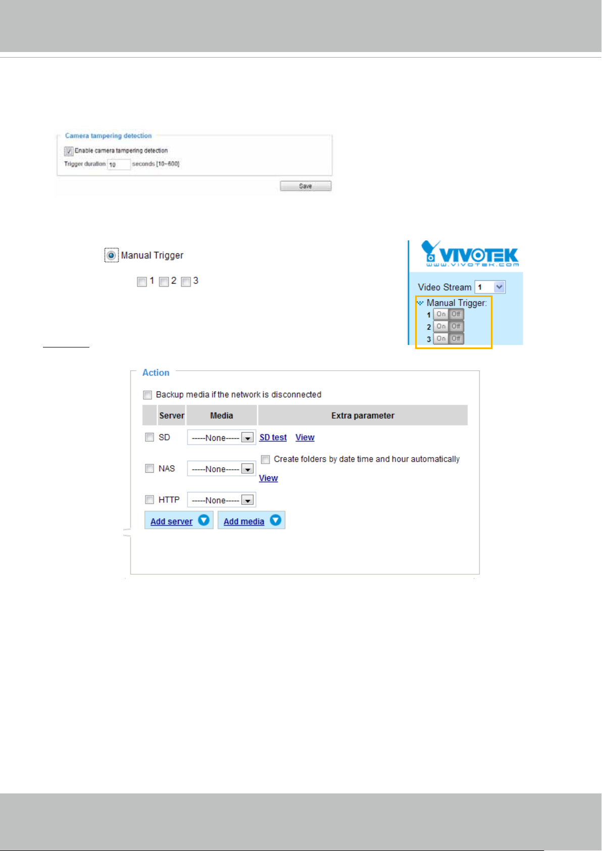
VIVOTEK
■ Camera tampering detection
This option allows the Network Camera to trigger when the camera detects that is is being tampered
with. To enable this function, you need to congure the Tampering Detection option rst. Please refer
to page 98 for detailed information.
■ Manual Trigger
This option allows users to enable event triggers manually by clicking the on/off button on the
homepage. Please congure 1 to 3 associated events before using this function.
3. Action
Dene the actions to be performed by the Network Camera when a trigger is activated.
■ Backup media if the network is disconnected
Select this option to backup media le on SD card if the network is disconnected. This function will only
be displayed after you set up a network storage (NAS).
84 - User's Manual
Page 85

VIVOTEK
Add server
To set an event with recorded video or snapshots, it is necessary to configure the server and media
settings so that the Network Camera will know what action to take (such as which server to send the
media les to) when a trigger is activated. Click
Add server
to open the server setting window. You can
specify where the notication messages are sent when a trigger is activated. A total of 5 server settings
can be congured.
There are four choices of server types available: Email, FTP, HTTP, and Network storage.
to display the detailed conguration options. You can congure either one or all of them.
Select the item
Server type - Email
Select to send the media les via email when a trigger is activated.
■ Server name: Enter a name for the server setting.
■ Sender email address: Enter the email address of the sender.
■ Recipient email address: Enter the email address of the recipient.
■ Server address: Enter the domain name or IP address of the email server.
■ User name: Enter the user name of the email account if necessary.
■ Password: Enter the password of the email account if necessary.
■ Server port: The default mail server port is set to 25. You can also manually set another port.
If your SMTP server requires a secure connection (SSL), select This server requires a secure
connection (SSL).
User's Manual - 85
Page 86

VIVOTEK
To verify if the email settings are correctly congured, click Test. The result will be shown in a pop-up
window. If successful, you will also receive an email indicating the result.
Click Save server to enable the settings.
Note that after you set up the rst event server, the new event server will automatically display on the
Server list. If you wish to add other server options, click Add server.
Server type - FTP
Select to send the media les to an FTP server when a trigger is activated.
■ Server name: Enter a name for the server setting.
■ Server address: Enter the domain name or IP address of the FTP server.
■ Server port: By default, the FTP server port is set to 21. It can also be assigned to another port number
between 1025 and 65535.
■ User name: Enter the login name of the FTP account.
■ Password: Enter the password of the FTP account.
■ FTP folder name
Enter the folder where the media le will be placed. If the folder name does not exist, the Network
Camera will automatically create one on the FTP server.
86 - User's Manual
Page 87

VIVOTEK
■ Passive mode
Most firewalls do not accept new connections initiated from external requests. If the FTP server
supports passive mode, select this option to enable passive mode FTP and allow data transmission to
pass through the rewall. The rmware default has the Passive mode checkbox selected.
To verify if the FTP settings are correctly congured, click Test. The result will be shown in a pop-up
window as shown below. If successful, you will also receive a test.txt le on the FTP server.
Click Save server to enable the settings.
Server type - HTTP
Select to send the media les to an HTTP server when a trigger is activated.
■ Server name: Enter a name for the server setting.
■ URL: Enter the URL of the HTTP server.
■ User name: Enter the user name if necessary.
■ Password: Enter the password if necessary.
To verify if the HTTP settings are correctly congured, click Test. The result will be shown in a pop-up
window as below. If successful, you will receive a test.txt le on the HTTP server.
Click Save server to enable the settings.
User's Manual - 87
Page 88

VIVOTEK
Network storage:
Select to send the media les to a network storage location when a trigger is activated. Please refer to
NAS server on page 102 for details.
Click Save server to enable the settings.
■ SD Test: Click to test your SD card. The system will display a message indicating success or failure. If
you want to use your SD card for local storage, please format it before use. Please refer to page 90 for
detailed information.
■ View: Click this button to open a le list window. This function is only for SD card and Network Storage.
If you click the View button of SD card, a Local storage page will pop up for you to manage recorded
les on SD card. For more information about Local storage, please refer to page 104. If you click the
View button of Network storage, a le directory window will prompt for you to view recorded data on
Network storage. For detailed illustration, please refer to the next page.
■ Create folders by date, time, and hour automatically: If you check this item, the system will generate
folders automatically by the date when video footages are stored onto the networked storage.
The following is an example of a le destination with video clips:
20100820
20100821
20100822
The format is: YYYYMMDD
Click to open the directory
Click to delete all recorded data
Click to delete selected items
88 - User's Manual
Page 89
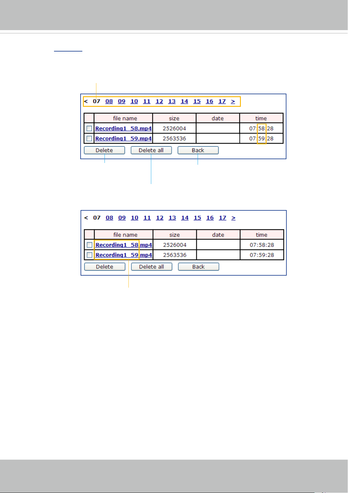
Click 20110220 to open the directory:
The format is: HH (24r)
Click to open the le list for that hour
VIVOTEK
2011/02/20
2011/02/20
Click to delete
selected items
Click to go back to the previous
level of the directory
Click to delete all
recorded data
2011/02/20
2011/02/20
The format is: File name prex + Minute (mm)
You can set up the file name prefix on the Add media page.
Please refer to next page for detailed information.
User's Manual - 89
Page 90

VIVOTEK
Add media
Click
Add media
to open the media setting window. You can specify the type of media that will be
sent when a trigger is activated. A total of 5 media settings can be congured. There are three choices
of media types available: Snapshot, Video Clip, and System log.
Select the item to display the detailed
conguration options. You can congure one or all of them.
Media type - Snapshot
Select to send snapshots when a trigger is activated.
■ Media name: Enter a name for the media setting.
■ Source: Select to take snapshots from any of the video streams.
■ Send pre-event images
The Network Camera has a buffer area; it temporarily holds data up to a certain limit. Enter a number
to decide how many images to capture before a trigger is activated. Up to 7 images can be generated.
■ Send post-event images
Enter a number to decide how many images to capture after a trigger is activated. Up to 7 images can
be generated.
For example, if both the Send pre-event images and Send post-event images are set to 7, a total of 15
images are generated after a trigger is activated.
1 pic. 2 pic. 3 pic. 4 pic. 5 pic. 6 pic. 7 pic. 8 pic. 9 pic.
Trigger Activation
10 pic. 11 pic. 10 pic. 12 pic. 13 pic. 14 pic. 15 pic.
■ File name prex
Enter the text that will be appended to the front of the le name.
90 - User's Manual
Page 91

■ Add date and time sufx to the le name
Select this option to add a date/time sufx to the le name.
For example:
Snapshot_20101213_100341
VIVOTEK
File name prefix
Date and time suffix
The format is: YYYYMMDD_HHMMSS
Click Save media to enable the settings.
To note that after you set up the first media server, a new column for media server will automatically
show up on the Media list. If you wish to add more other media options, click Add media.
Media type -
Video clip
Select to send video clips when a trigger is activated.
■ Media name: Enter a name for the media setting.
■ Source: Select the source of video clip.
■ Pre-event recording
The Network Camera has a buffer area; it temporarily holds data up to a certain limit. Enter a number
to decide the duration of recording before a trigger is activated. Up to 9 seconds can be set.
■ Maximum duration
Specify the maximum recording duration in seconds. Up to 10 seconds can be set.
For example, if pre-event recording is set to five seconds and the maximum duration is set to ten
seconds, the Network Camera continues to record for another 4 seconds after a trigger is activated.
1 sec. 2 sec. 3 sec. 4 sec. 5 sec. 6 sec. 7 sec. 8 sec. 9 sec. 10 sec.
Trigger Activation
User's Manual - 91
Page 92

VIVOTEK
■ Maximum le size
Specify the maximum le size allowed.
■ File name prex
Enter the text that will be appended to the front of the le name.
For example:
Video_20101213_100341
File name prefix
Date and time suffix
The format is: YYYYMMDD_HHMMSS
Click Save media to enable the settings.
Media type - System log
Select to send a system log when a trigger is activated.
Click Save media to enable the settings, then click Close to exit the page.
92 - User's Manual
Page 93

VIVOTEK
In the Event settings column, the Servers and Medias you congured will be listed; please make sure the
Event -> Status is indicated as ON, in order to enable the event triggering action.
When completed, click Save event to enable the settings and click Close to exit Event Settings page.
The new Event / Server settings / Media will appear in the event drop-down list on the Event setting
page.
Please see the example of the Event setting page below:
When the Event Status is ON, once an event is triggered; for example, by motion detection, the Network
Camera will automatically send snapshots via e-mail.
If you want to stop the event trigger, you can click ON to turn it to OFF status or click Delete to remove
the event setting.
To remove a server setting from the list, select a server name from the drop-down list and click Delete.
Note that you can only delete a server setting when it is not applied to an event setting.
To remove a media setting from the list, select a media name from the drop-down list and click Delete.
Note that you can only delete a media setting when it is not applied to an event setting.
User's Manual - 93
Page 94

VIVOTEK
Customized Script
This function allows you to upload a sample script (.xml le) to the webpage, which will save your time on
conguring the settings. Please note that there is a limited number of customized scripts you can upload;
if the current amount of customized scripts has reached the limit, an alert message will prompt. If you
need more information, please contact VIVOTEK technical support.
Click to upload a le
Click to modify the
script online
94 - User's Manual
Page 95

VIVOTEK
Applications > Motion detection
This section explains how to congure the Network Camera to enable motion detection. A total
of three motion detection windows can be congured.
2010/12/10 17:08:56
Motion Detection Setting 1:
For normal situations
Follow the steps below to enable motion detection:
For special situations
Follow the steps below to enable motion detection:
Motion Detection Setting 2:
1. Click New to add a new motion detection window.
2. In the Window Name text box, enter a name for the motion detection window.
■ To move and resize the window, drag and drop your mouse on the window.
■ To delete a window, click X on the upper right corner of the window.
3. Define the sensitivity to moving objects and the space ratio of all alerted pixels by moving the
Sensitivity and Percentage slider bar.
4. Click Save to enable the settings.
5. Select Enable motion detection to enable this function.
For example:
Video(TCP-AV)
window
2010/12/10 17:08:56
The Percentage Indicator will rise or fall depending on the variation between sequential images. When
motions are detected by the Network Camera and are judged to exceed the defined threshold, the
red bar rises. Meanwhile, the motion detection window will be outlined in red. Photos or videos can be
captured instantly and congured to be sent to a remote server (Email, FTP) by utilizing this feature as a
trigger source. For more information on how to set an event, please refer to Event settings on page 82.
User's Manual - 95
Page 96

VIVOTEK
A green bar indicates that even though motions have been detected, the event has not been triggered
because the image variations still fall under the dened threshold.
Percentage = 30%
If you want to congure a motion detection setting for a different scenario, please click Prole to open
the Motion Detection Prole Settings page as shown below. A total of three motion detection windows
can also be congured on this page.
Video(TCP-AV)
2010/12/10 17:08:56
Please follow the steps beolw to set up a prole:
1. Create a new motion detection window.
2. Check Enable this prole.
3. Select the applicable schedule for the current setting. Please manually enter a range of time during
which the conguration will take effect.
4. Click Save to enable the settings and click Close to exit the page.
This motion detection window will also be displayed on the Event Settings page. You can go to Event
> Event settings > Trigger to choose Motion Detection as a trigger source. Please refer to page 100 for
detailed information.
96 - User's Manual
Page 97

VIVOTEK
NOTE
NOTE:
► How does motion detection work?
A
B D
C
There are two motion detection parameters: Sensitivity and Percentage. In the illustration above,
frame A and frame B are two sequential images. Pixel differences between the two frames are
detected and highlighted in gray (frame C) and will be compared with the sensitivity setting. Sensitivity
is a value that expresses the sensitivity to moving objects. Higher sensitivity settings are expected to
detect slight movements while smaller sensitivity settings will neglect them. When the sensitivity is set
to 70%, the Network Camera denes the pixels in the purple areas as “alerted pixels” (frame D).
Percentage is a value that expresses the proportion of “alerted pixels” to all pixels in the motion
detection window. In this case, 50% of pixels are identied as “alerted pixels”. When the percentage is
set to 30%, the motions are judged to exceed the dened threshold; therefore, the motion window will
be outlined in red.
For applications that require a high level of security management, it is suggested to use higher
sensitivity settings and smaller percentage values.
User's Manual - 97
Page 98

VIVOTEK
Applications > DI and DO
Advanced Mode
Connect a Digital Input device to the camera's terminal block, the camera will automatically
detect the current connection state as pulled-high or pulled-low. You may then define the
triggering condition.
Digital input: Select High or Low to dene the "Normal status" for the digital input. The Network
Camera will report the current status.
Applications > Tampering detection
This section explains how to set up camera tamper detection. With tamper detection, the
camera is capable of detecting incidents such as redirection, blocking or defocusing, or even
spray paint.
Please follow the steps below to set up the camera tamper detection function:
1. Check Enable camera tampering detection.
2. Enter the tamper trigger duration. (10 sec. ~ 10 min.) The tamper alarm will be triggered only
when the tampering factor (the difference between current frame and pre-saved background)
exceeds the trigger threshold.
3. Set up the event source as Camera Tampering Detection on Event > Event settings >
Trigger. Please refer to page 100 for detailed information.
98 - User's Manual
Page 99

VIVOTEK
Recording > Recording settings
Advanced Mode
This section explains how to congure the recording settings for the Network Camera.
Recording Settings
Insert your SD card and click here to test
NOTE
NOTE:
► Please remember to format your SD card when using it for the rst time. Please refer to page 104 for
detailed information.
Recording Settings
Click Add to open the recording setting window. On this page, you can dene the adaptive recording,
recording source, recording schedule, and recording capacity. A total of 2 recording settings can be
congured.
■ Recording name: Enter a name for the recording setting.
■ Enable this recording: Select this option to enable video recording.
■ With adaptive recording:
Select this option will activate the frame rate control according to alarm trigger.
The frame control means that when there is a triggered alarm, the frame rate will raise up to the value
you’ve set on Video quality page. Please refer to page 49 for more information.
User's Manual - 99
Page 100

VIVOTEK
If you enable adaptive recording and enable time-shift cache stream on Camera A, only when an event
is triggered on Camera A will the server record the full frame rate streaming data; otherwise, it will only
request the I frame data during normal monitoring, thus effectively save lots of bandwidths and storage
space.
NOTE
NOTE:
► To enable adaptive recording, please make sure
you’ve set up the trigger source such as Motion
Bandwidth
I frame ---> Full frame rate ---> I frame
Bandwidth
Activity Adaptive Streaming
for Dynamic Frame Rate Control
Detection, DI Device, or Manual Trigger.
► When there is no alarm trigger:
- JPEG mode: record 1 frame per second.
- H.264 mode: record I frame only.
- MPEG-4 mode: record the I frame only.
► When the I frame period is >1s on Video settings
page, firmware will force decrease the I frame
period to 1s when adaptive recording is enabled.
Continuous recording
Time
The alarm trigger includes: motion detection and DI detection. Please refer to Event Settings on page 82.
■ Pre-event recording and post-event recording
The Network Camera has a buffer; it temporarily holds data up to a certain limit. Enter a number to
decide the duration of recording before and after a trigger is activated.
■ Priority: Select the relative importance of this recording (High, Normal, or Low). Recording with a higher
priority setting will be executed rst.
■ Source: Select a stream as the recording source.
NOTE
NOTE:
► To enable recording notication please congure Event settings rst . Please refer to page 82.
Please follow the steps below to set up a recording setting.
1. Trigger
Select a trigger source.
■ Schedule: The server will start to record les on the local storage or network storage (NAS).
■ Network fail: In the event of a network failure, the server will start to record media les on the local
storage (SD card).
100 - User's Manual
 Loading...