

Page 1
VIVOTEK Fixed Dome Series
Mounting Bracket
Installation Guide
Using AM-51E mounting bracket
and compatible accessories
Ordering part no.:100171300G
QIG Part no.: 625043100G
IP Surveillance
Rev. 1.0
Page 2
Revision History:
* Rev. 1.0: Initial Release
Compatible VIVOTEK Cameras
I
Fixed Dome series
You may also refer to VIVOTEK's website for the list of supported models. Support for other models can
be available through time.
Package Contents
II
Installation
FD8366-V, FD8166A, FD8166A-N
: AM-51E, Installation Guide, 4x panhead M3x5.
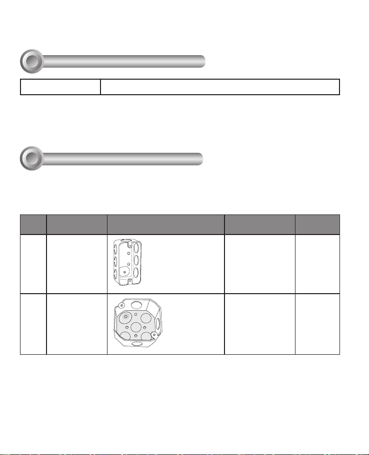
Mounting Hole Denitions
Below are the locations of different groups of mounting holes for matching different junction
boxes:
Hole
Applicable Box Drawings Screw No. of
Type
A
B
4" x 2" handy
box, 1-1/2"
deep, 1/2" end
knockouts
3.5" octagon
box, 1-1/2"
deep, 1/2" side
knockouts
#6-32, L15
(User-supplied)
#8-32, L15
(User-supplied)
screws
2
2
2
Page 3
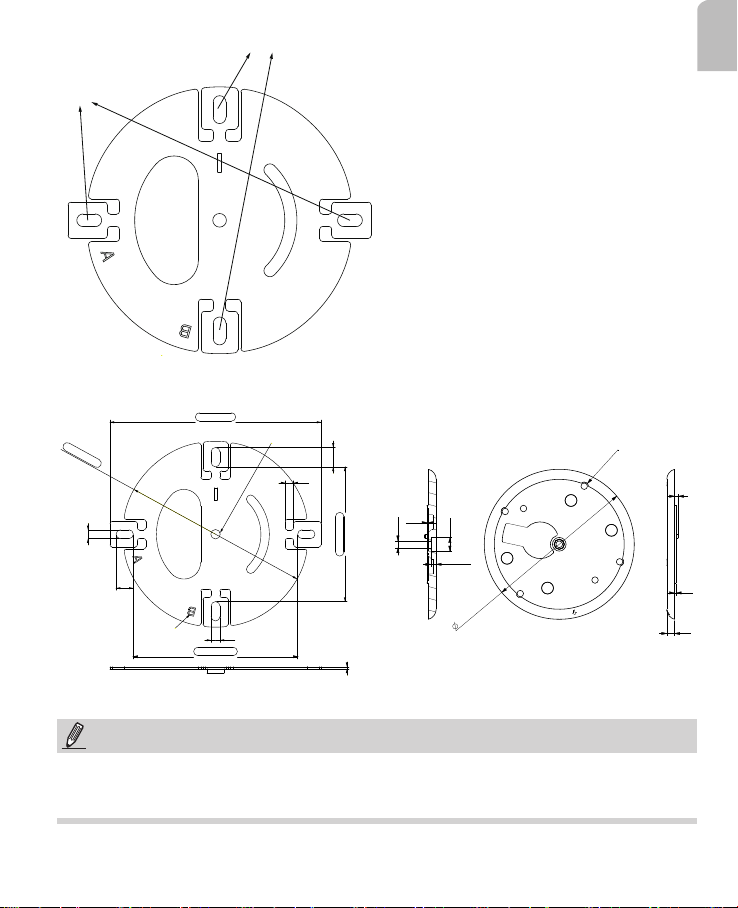
B holes
A holes
AM-51E Mounting Bracket Mechanical Drawings
A_100` 0.2
B_n88 ` 0.2
4.2
8.2
電腦刻字(穿透)
C_77.8 ` 0.2
NUT-M5
4.2
9.2
4
0.9
5.2
D_63.8 ` 0.2
1
English
NUT-M3-6X
A2
A3
10.5
4.1
A4
115.65
A1
A6
A5
3
1.2
6
NOTE:
1. Route cables before you secure the accessories to a wall.
2. For details on the cabling connections with network cameras, please refer to their
Quick Installation Guide.
3
Page 4

Installing the Mounting Bracket
1. Route cables through the junction box.
2. Install the bracket to the junction box using either the A or B holes.
Before installation, align the A mark on the base
plate with that on the rotation plate. If using the
3.5" octagon box, align the B marks.
Turn the rotation plate to align the through
holes with the mounting holes on the box.
When installing to junction box, use screws
with heads smaller than Ø8.5 mm
A1
A2
A3
A6
A5
A4
4
Page 5

IMPORTANT:
Install the bracket with the arrow mark pointing toward the shooting direction you prefer.
If installed high on the wall, the arrow mark should be pointing down.
If the junction box became deformed during the construction process, you can detach
the rotation plate and install the bracket separately.
English
M5*8, Pan head
Nylon spacer_D5.1*D10*1.0
Nylon spacer_D5.1*D10*1.0
Mount bracket, AM-51E
Rotattion plate, AM-51E
5
Page 6

Note that you can still adjust the shooting direction by 90 degrees by turning the rotation
plate.
3. Route cables through the cabling hole.
4. Pass cables through the waterproof rubber seal and complete all cabling requirements
as documented in the camera QIG.
10cm
6
Page 7

5. Align the camera's shooting direction with the arrow mark, and you can nd and match
the mouting holes. Tighten the screws to install camera.
FD8366-V
English
A6
FD8166A Series
A6
A5
A1
A5
A1
A4
A3
A2
A4
A3
A2
7
Page 8

6. Tune and focus, and refer to the documentation that came with your cameras for the
rest of conguration details. Install the dome cover.
M3X5
FD8166A
FD8166A top cover
AM-51E
FD8366-V top cover
M3X5
T10 driver
FD8366-V
AM-51E
3.5” box
8
 Loading...