

Page 1
AM-516
Adaptor Ring
User’s Manual
Corresponding part number: 909001600G
Rev. 1.1
IP Surveillance
Page 2
Overview
I
AM-516 Adaptor Ring
Adaptor ring for FD8162 xed dome camera. The
supported installation types are:
1. to a 90º wall-mount bracket (AM-214).
2. to a 4" or 4
You may also refer to VIVOTEK's website for the list of supported models.
Supported Models: FD8162, FD8163, FD8135H, FD8171, FD8155H, FD8165H, FD8173H, FD8181
Installation with a Wall-mount Bracket (AM-211)
II
11/16
" US standard, metal junction box.
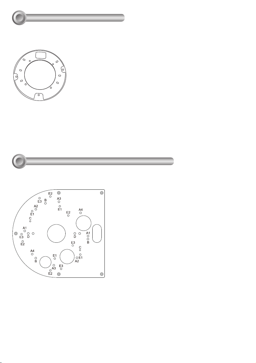
Mounting Hole Denitions
Use the A group holes for the supported cameras.
2
Page 3
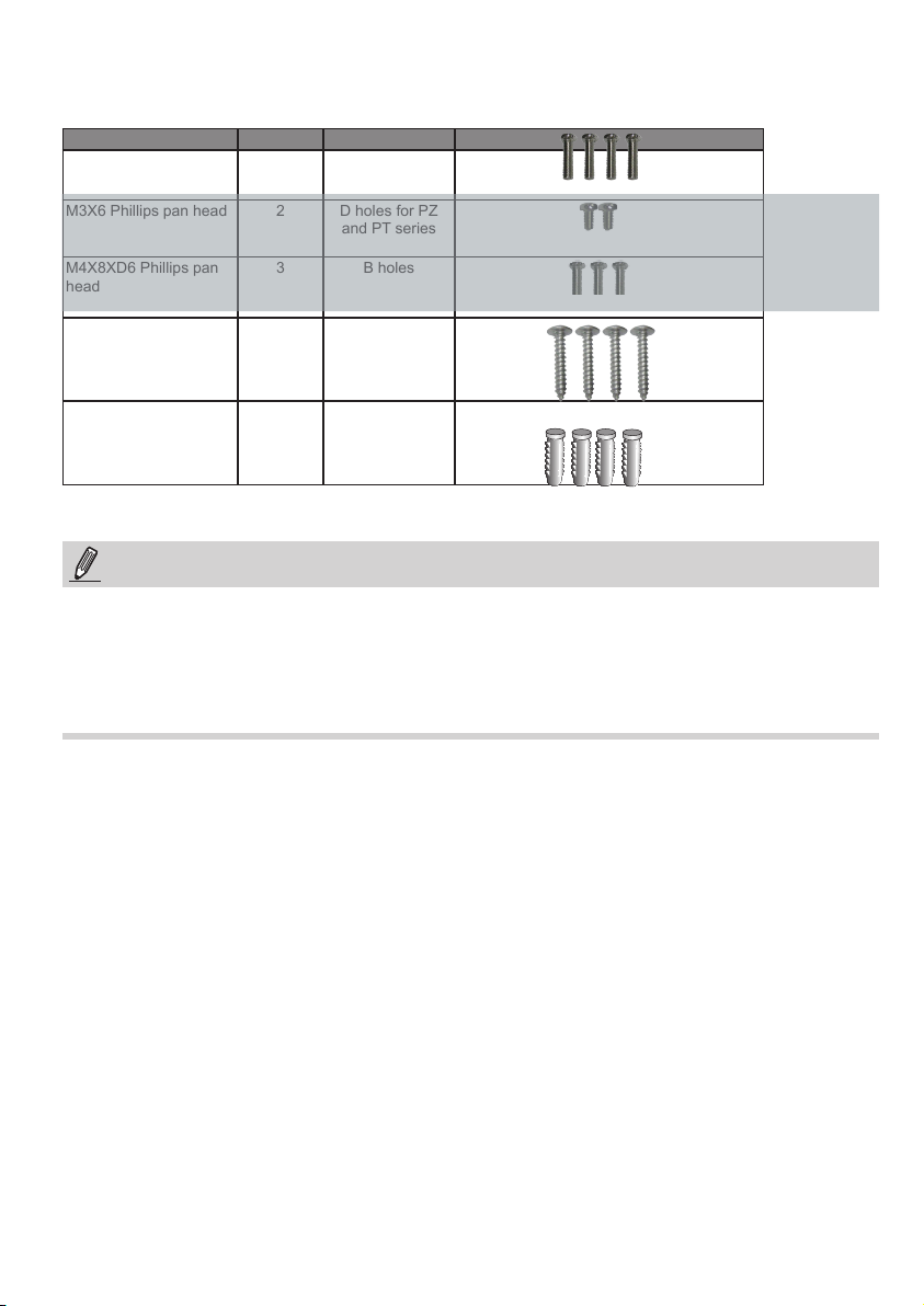
Refer to the table below for the description of the included screws:
Screw Description Quantity Applies to
M4X15 Phillips pan head 4 A holes
M3X6 Phillips pan head 2
NOT USED!
M4X8XD6 Phillips pan
head
M4X25XD9 Phillips pan
head
Plastic anchors 4 Securing the
NOTE:
1. It is presumed that the corresponding AM-211 wall-mount bracket is installed with a hole drilled on the
wall for routing power lines, DI/DO, and Ethernet cables.
2. Route cables before you secure the wall-mount bracket to a wall.
3. For details on the cable connections with each camera, please refer to their Quick Installation Guide.
D holes for PZ
and PT series
3 B holes
4 Securing the
bracket to wall
bracket to wall
Page 4

Wall Mount Installation
Below is a sample procedure using AM-214 wall mount bracket and an FD8162:
1. Determine a hard surface wall location, and use the four mounting holes on the bracket to mark the
positions where holes will be drilled to secure the bracket.
A* holes
M4X15
Camera Lens Orientation
2. Drill holes on the wall for securing the bracket and for routing cables.
3. Route cables through the wall and bracket.
4. Secure the wall mount bracket to the wall using the included screws and plastic anchors.
5. Rotate the adaptor ring to match the camera lens orientation your prefer, e.g., to the front or to the left.
Secure the adaptor ring to bracket using the M4X15 screws to the A2 and A4 holes on the bracket.
4
Page 5

6. Secure the camera to the adaptor ring using the included screws.
7. Connect power lines and cables to the camera.
8. Proceed with initial setup such as enabling network access, focus tuning, or zooming. When done,
secure the outer dome cover.
NOTE:
Use the correct type of screws when installing cameras to the mounting cap. Refer to page 2 for the
screw type.
English
5
Page 6

Ceiling Mount to a Junction Box
III
Below are the basic dimensions of standard, US style, 4 in. or 4 11/16 in. junction boxes. The AM-516
adaptor ring complies with such junction box.
6.75 [17/64] DIA. HOLE MIN. OF FOUR
LOCATED AS SHOWN
101.60 [4]
85.72 [3 3/8]
85.72
[3 3/8]
THREE 1/2 [16] KNOCKOUTS
IN BOTTOM
TWO 1/2 [16] OR 3/4 [21] KNOCKOUTS
IN BOTTOM
119.06 [4 11/16]
69.85
[2 3/4]
[3 3/4]
CLEAR.
THREE 1/2 [16] KNOCKOUTS
IN BOTTOM
D KNOCKOUTS, TWO
REQD. IN BOTTOM
#8-32 TAP
2 HOLES
101.60
[4]
OPTIONAL
MOUNTING
HOLES
THREE 1/2 [16] KNOCKOUTS ON
D REF.
OPPOSITE SIDES
6.75 [17/64] DIA. HOLE
MIN. OF FOUR
LOCATED AS SHOWN
119.06
[4 11/16]
107.95
95.26
[4 1/4]
MIN.
#8-32 TAP
4 HOLES
THREE 1/2 [16] KNOCKOUTS ON
EACH SIDE, 12 REQD. TOTAL
OPTIONAL
MOUNTING
HOLES
Align the adaptor ring with holes on the junction box
following the markings on the ring.
Use the included 8# 1/2 screws for mounting to a
junction box.
6
Page 7

Orient the adaptor ring to match the tap holes on the junction box, so
that the camera's shooting angle can be more easily directed to the area
of your interest, although the camera comes with mechanisms to adjust
lens orientation.
Note that the junction box should be able to carry a weight of at least 3
kilograms.
Camera Lens Orientation
To install camera with the adaptor ring:
1. Use the included machine screws to fasten the adaptor ring to a 4 in. or 4 11/16 in. junction box.
2. Route cables through the opening.
3. Secure the camera to the adaptor ring onto the 3 elevated mounting holes.
4. Connect the cabling, use the Ethernet connection to open a web console. Adjust the camera's shooting
angle, focus, and zoom. When done, install the dome cover.
8# 1/2
Machine screws
Nickel
alloy
English
M4*12mm
Panhead screws,
black
7
Page 8

This page is intentionally left blank.
8
 Loading...