

VIVOTEK Mounting Accessories
Mechanical Drawings
II
AM-411 Corner mount
Installation Guide
Revison History:
Rev. 1.0: Initial release
Corresponding part numbers:
AM-411: 900003003G (v04)
900003004G (v05)
AM-711: 900005100G
AM-221: 900014800G
AM-212: 900004202G
Compatible VIVOTEK Cameras
I
Type Compatible cameras/brackets Brackets
A AM-212/221,
SD8363E, SD8364E, SD83x4E, SD83x6E, SD8333E,
w/ AM-519 (900014900G )
B AE2000/ AE234/ 235/ 211/ 232/ 233 AM-311/411/711
C Medium Bullet, see below for compatibility. AM-311/411
D Large Bullet, see below for compatibility. AM-311/411
AM-411 Support List
Large Bullet Medium Bullet Ball swivel bracket
V04: 900003003G
IP8371E IP8335H
IP8372 IP8362
IB8373-EH
IP8355EH
IP8365EH
V05: 900003004G (V05 is backward compatible with the bullets supported by V04)
IB8381-E IP8364-C
IP8337H-C
IB8354-C
IB8367(-R)
IB8338-H(R)
AM-311/411/711
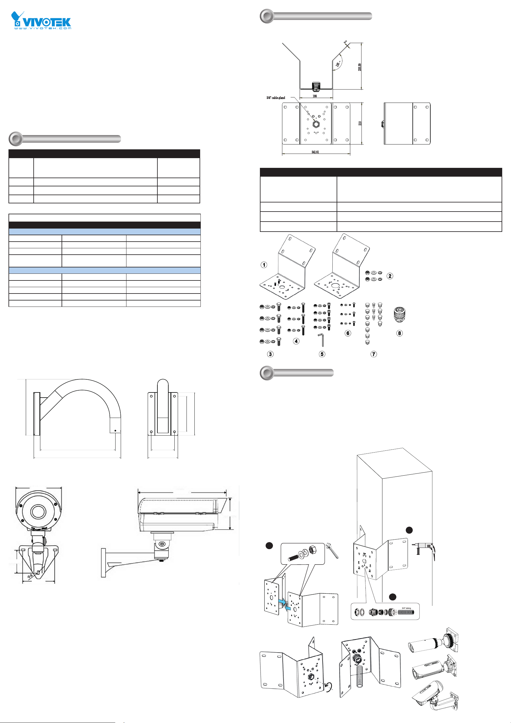
AM-411 Corner mount bracket
2
~
135
3/4" cable gland
Package Contents
Items 1. Corner mount brackets, 2. Screws for combining the corner mount
Box Net Weight 2.9 kgs each box
Box Gross Weight 7.75 kgs 2 boxes in one carton
Outer carton Dimensions 455 x 285 x 365mm
166
341.61
233.39
210
brackets, 3. M8X25mm screws, 4. M6X35mm screws, 5. M6X20 screws
6. M4X15 screws, 7. silicone plugs, 8. 3/4" waterproof corrugated tubing
ttings
AM-221 Gooseneck
262.19
AE20xx Series Enclosure
160mm
350 107.8
405.8
140
425mm
165.5
200
165mm
Installation
III
III-1. Corner mount installation: AM-411
Below is a general, sample procedure using a Corner mount bracket:
1. Combine the two brackets together using the included nuts and washers.
2. Align the assembled brackets with the desired position. Align screw holes on the brackets against the wall.
Drill holes on the wall for securing the bracket and for routing the cables. Hammer anchors into the wall. Wall
anchors are user-supplied.
3. Route power lines and other cables through the included cable gland, conduits (separately purchased),
and install the cable gland to the brackets' through the hole in the center. For cabling details, refer to the
documentation that came with your accessories or network camera.
IMPORTANT:
Refer to the mounting holes for specic
cameras for the orientation of the
bracket. You can mistakenly install the
bracket upside down.
2
68.5mm
83.2mm
1
Cable gland and 3/4"
conduits
3
NOTE: Do not apply the cable gland
when using the following camera
types:
Ball-swivel
bracket
Large bullet
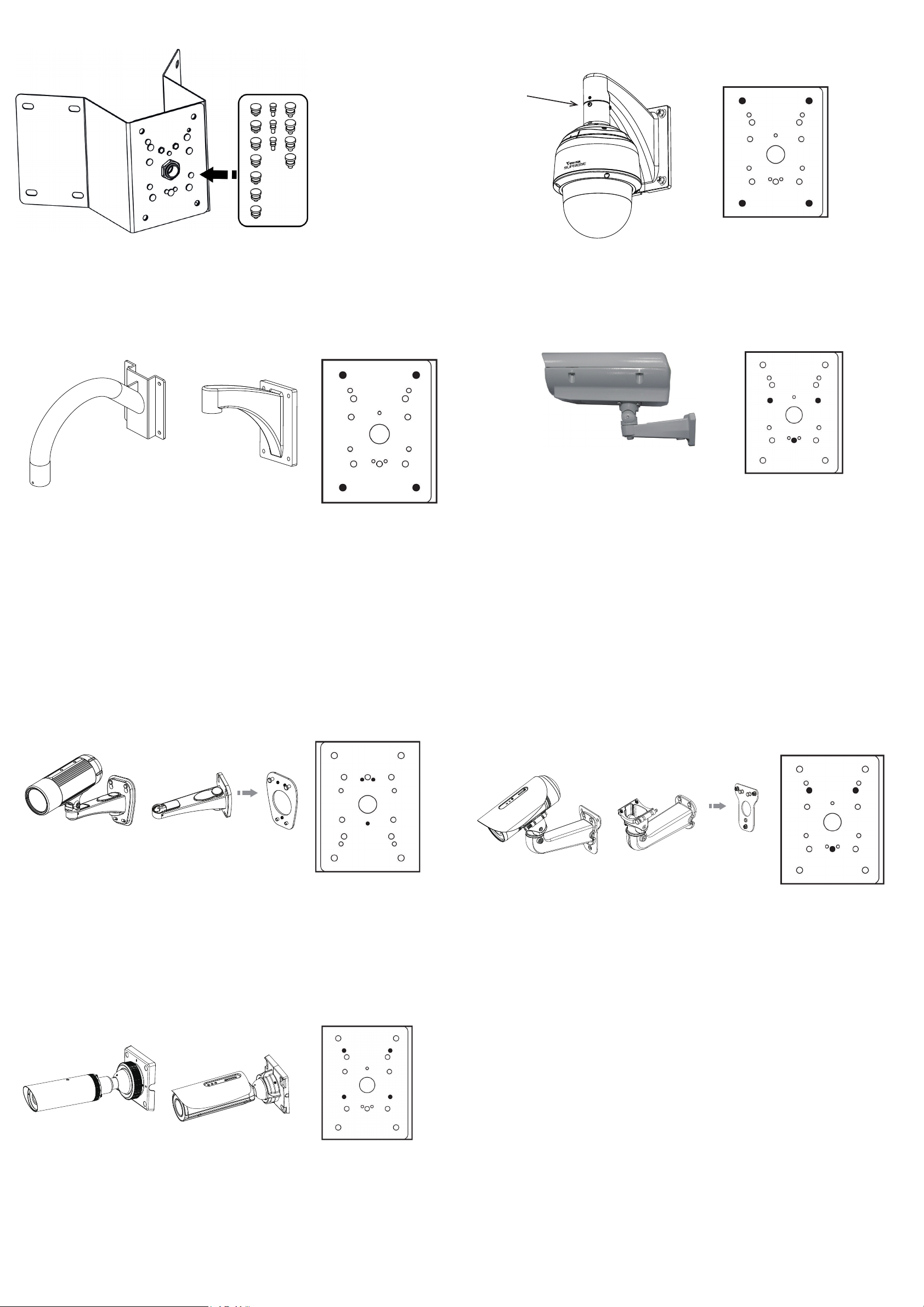
Fill the unused holes on the bracket using the included silicone stoppers. Please check the following drawings for
the mounting holes and the unused holes for your models.
III-4. Speed dome installation: SD83xx Series
Align the mounting holes on the bracket with the mounting holes (as shown in the drawing), and secure it using
the included hex bolts, washers, and nuts.
AM-519 inside
HD WDR Pro
Speed dome
III-3. Goose neck installation: AM-221 and AM-212
Align the mounting holes on the bracket with the mounting holes (as shown in the drawing), and secure it using
the included hex bolts, washers, and nuts. The enclosure is mounted later after its wall-mount bracket is securely
attached.
Align the mounting holes on the bracket with the mounting holes, and secure it using the included hex bolts,
washers, and nuts.
AM-212AM-221
Use M8X25mm screws
NOTE: There is no need to apply silicone stoppers to the AM-221.
Use M8X25mm screws
III-5. AE series enclosure installation: AE2000 and others
AE series enclosures
Use M6X35mm screws
III-6. Camera installation - Medium Bullet: IP8335/8352/8362
Align the mounting holes on the bracket with the mounting holes (as shown in the drawing), and secure it using
the included hex bolts, washers, and nuts.
IP8335/8352/8362
III-7. Camera installation - Medium Bullet: IP8337-H/8364/8364-C, IB8367-R, 8338-HR, 8367-RT
Align the mounting holes on the bracket with the mounting holes (as hsown in the drawing), and secure it using
the included hex bolts, washers, and nuts.
III-8. Camera installation - Large Bullet: IP8371E, IP8372, IB8373-EH, IB8381(-E), IP8355(E)H,
IP8365(E)H, IP8335H, IP8362
Align the mounting holes on the bracket with the mounting holes (as shown in the drawing), and secure it using
the included hex bolts, washers, and nuts. Refer to the camera's documentation for the rest of the details.
Use M6X35mm screwsUse M4X15mm screws
IP8337-H, 8364, 8354-C
IB8367-R, 8338-HR, 8367RT
Use M6X20mm screws
 Loading...