

Page 1
VIVOTEK Fixed Dome Series
Wall-mount Bracket
Installation Guide
Using AM-21G wall-mount bracket
and compatible accessories
Corresponding part number:
AM-21G: 100200200G AM-21G_V01
QIG part no.: 625049500G
Rev. 1.0
IP Surveillance
Page 2
Revision History:
* Rev. 1.0: Initial Release
Compatible VIVOTEK Cameras
I
FD8366-V, MD8565-N
You may also refer to VIVOTEK's website for the list of supported models. Support for other models can
be available through time.
Installation
II
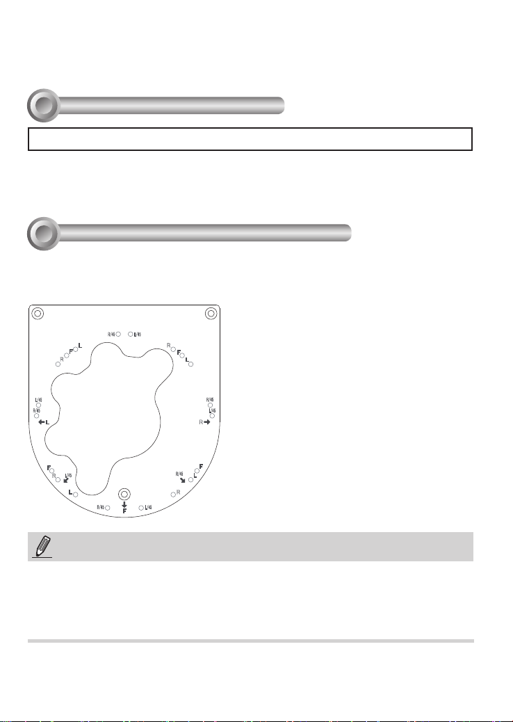
Mounting Hole Denitions
Below are the locations of mounting holes.
R/4 5
L
F
R
L/4 5
R
F
L
L/4 5
R/4 5
L
F
L/4 5
R
L
R/4 5
L/4 5
F
R/4 5
L/4 5
R
F
R/4 5
L
R
NOTE:
1. It is presumed that this wall-mount bracket is installed with a hole drilled on the wall for
routing power wires, DI/DO, and Ethernet cables.
2. Route cables before you secure the wall-mount bracket to a wall.
3. For details on the cable connections with each camera, please refer to their Quick
Installation Guide.
2
Page 3

For cabling and conguration details with each network camera, please refer to their
documentation.
Refer to the table below for the description of the included screws:
Screw Description Quantity Applies to
M4X25XD7 Phillips pan
head
4 Securing the
bracket to wall
English
Plastic anchors 4 Securing the
bracket to wall
Wall Mount Installation
Below is a general, sample procedure using a wall mount bracket:
1. Locate the position where you want to install the wall mount bracket and camera. Drill
holes on the wall for securing the bracket and for routing the cables.
2. Secure the bracket by hammering anchors into the wall and then fasten screws through
the four mounting holes on the bracket.
3
Page 4

3. Route power lines and other cables through the wall and the bracket.
4. Turn the camera towards the eld of view of your interest. Note that the orientation
(camera lens) is separated by every 45º. The available shooting direction is illustrated
below. When done, align the camera's screw slots with the corresponding mounting
holes.
5. Secure the camera to the wall mount.
6. Install the dome cover using the included T10 driver in the camera's package.
R/4 5
L
F
R
L/4 5
R
F
L
L/4 5
R/4 5
L
F
L/4 5
R
L
R/4 5
L/4 5
F
R/4 5
L/4 5
R
F
R/4 5
L
R
Usable holes
at this orientation
Shooting direction
45º
4
 Loading...