

Page 1

VIVOTEK Fixed Dome Series
AM-105 Recessed-mount Bracket
Installation Guide
Corresponding part number: 900026802G
Rev. 1.2
IP Surveillance
Page 2
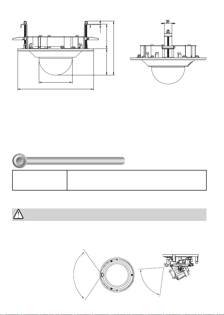
AM-105 Recessed-mount Bracket Mechanical Drawing
1,6
66,2
146,1
71,5
Ø
90
Ø
205
20
Package Contents
• Recessed-mount bracket
• Screws: 3x round head M4x8L; 3x round head
M3x8L .
• Alignment sticker
• Screwdriver: T10 stardriver
Compatible VIVOTEK Cameras
I
Fixed Dome series
FD816BA-HF2, FD816BA-HT, FD8182-F2, FD8182-T,
Revision History
• Rev. 1.0: Initial release.
• Rev. 1.1: Updated for new models–
HF2, FD816BA-HT, FD8182-F2, FD8182-T, FD9171HT, FD9181-HT, FD9165-HT, FD9167-H, FD9167-HT,
FD8177-HT
• Rev. 1.2: Added FD9187-H, -HT
FD816BA-
FD9171-HT, FD9181-HT, FD9165-HT, FD9167-H, FD9167-HT,
FD8177-HT, FD9187-H/-HT
You may also refer to VIVOTEK's website for the list of supported models. Support for other models can
be available through time.
IMPORTANT:
Before installing your camera, make sure the built-in PIR (Passive Infrared Sensor) can be
directed toward the area of interest, where possible intrusion may occur. (The sensitivity
of PIR sensor depends on the object size and temperature differences between the object
and the background environment.)
121°
5M
Top View
77.3°
5M
Side View
2
Page 3
Installation
II
Mounting Hole Denitions
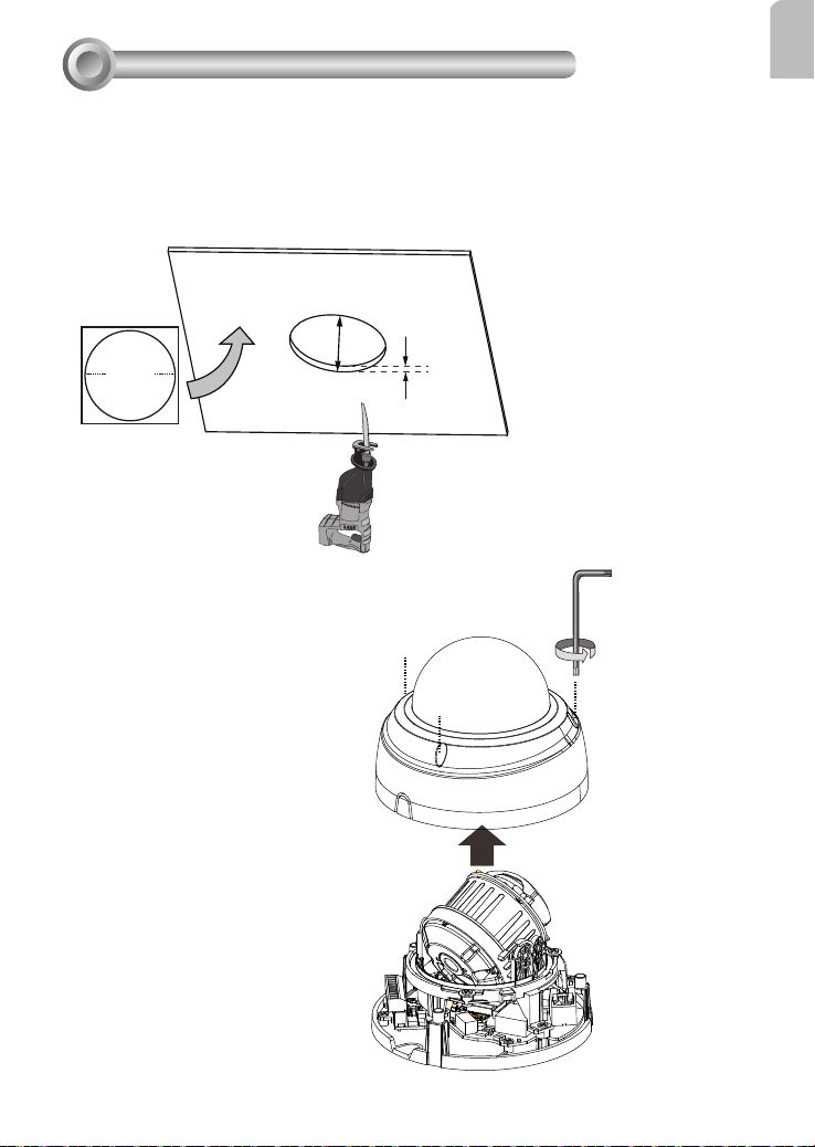
1. Determine a secure location for the recessed-mount bracket.
2. Drill or cut a 186mm hole (in diameter). The maximum thickness of the ceiling/board is
24mm. The ceiling board should be able to sustain at least a weight of 1.4kg.
186mm
Up to
Ceiling Hole Template Sticker
190mm
3. Remove dome cover from the camera
using the stardriver included in kit.
24mm
English
3
Page 4

4. Use the included T10 stardriver to detach the dome cover from the recessed mount
bracket.
5. Remove the breakaway tab from the bottom of the camera so that you can route cabIes
through the opening.
4
Page 5

6. Install camera to the recessed-mount bracket by driving 3 screws.
M4
M3
M3 M4
M4
M3
English
M3
M4
Mount hole Applicable models Screws
M4 FD9165-HT, FD9167-H/HT, FD8177-HT,
3x round head M4X8L
FD9187-H/-HT
M3 FD8182F2/T, FD9171-HT, FD9181-HT,
3x round head M3X8L
FD816BA-HT/HF2
NOTE:
1. Connect and route cables before you secure the recessed-mount bracket to a ceiling.
2. For details on the cabling connections with each camera, please refer to their Quick
Installation Guide.
5
Page 6

7. Pass cables through the routing hole and connect cables to the camera.
8. Use a #2 Phillips screwdriver to loosen the clamping plates (see drawing below) and
insert the recessed-mount bracket through the hole in the ceiling.
6
Page 7

9. Use a #2 Phillips screwdriver to move the clamping plates down so that the ceiling/
board is caught between the clamps and the ange on the other side of the ceiling.
Clockwise Counter-
clockwise
10. Adjust the shooting angle and check for a satisfactory image over a web session.
When you have a satisifactory live view, tighten the tilt screw, and secure the dome
cover from below the ceiling using the T10 stardriver.
English
7
Page 8

11. You are done with the installation.
IMPORTANT:
The ceiling mount conguration does not support the Corridor view. If using the Corridor
view, some part of the view area may not be properly revealed.
8
 Loading...