

Page 1
AI1002
IR Illuminator
Installation Guide
Rev. 1.0
IP Surveillance
Page 2
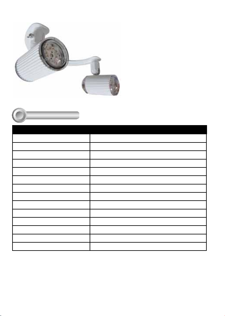
AI1002 Tube Type Infrared Illuminator
Specications
I
Model Number AI1002
IR LED quantity 12 pcs in 2 tube housings
IR light range 30~40 meters
IR wavelength 850nm
IR bean angle 60°
IR light control. CTRL (+/-) by camera
Input voltage AC 90~240V
Output voltage DC 12V
Operating current (constant) 500mA
Power consumption 6Watt
Operating temperature -10°C ~ +40°C
Storage temperature -20°C ~ +60°C
Dimensions 60mm (O.D) x 80mm (L) x 106mm (H)
Weight 1.5 kg
2
Page 3
Mounting & Cabling
II
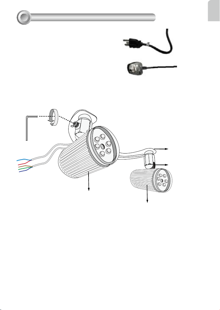
Preparing for installation:
1. Remove the IR illuminator from its package.
2. You should purchase power cords with
adequate length.
3. A T20 hex wrench.
Assemble the IR illuminator with the Support
Bracket. Use the included hex wrench to
assemble the support bracket, bearing housing,
and the ball swivel on the illuminators.
Use the included hex wrench to slightly loosen the ball swivel to adjust the shooting angle.
Support bracket
Ball swivel
English
IR illuminator
IR illuminator
3
Page 4

Install the IR illuminator behind your network camera, i.e., FD8362/FD8362E. Orient its
shooting angle after you slightly loosened the ball swivel screws. Secure the illuminators'
shooting angle by fastening socket screws on the ball swivels.
If you drilled a hole on the wall, you can pass power lines through the hollow of the
illuminator bracket and then through the hole.
271.3mm
Camera
Illuminator bracket
180.6mm
Mounting hole
* The IR tube housings have been
removed from this drawing for
simplicity sake.
Mounting hole
When planning the surveillance area, take into account the achievable distance. Optimal
results can be achieved by setting up at night and observing the results on a management
session screen. Adjust the illuminators' shooting angles so that the camera's eld of view
is correctly lit..
39.6°
118.9°
Near View Plane
60° projection angle
Max. 40m
View Plane
Far View Plane
4
Page 5

Wiring
III
There are 5 wires with the illuminators: 3 for power connections and another 2 as control
lines to the Digital outputs from a network camera. Refer to the diagram below for details.
Power cords
Connector Block
Dark Blue: AC input
Green: GND
Brown: AC input
Red
English
To Camera
GPIO Block
Light Blue
AC Power Connection
Power lines are connected to a power cord with a power plug. Use them to connect the
power cords you separately purchased.
Control Line Connection
The DI/DO terminal block is accessed by opening the camera dome cover.
Dome Cover Terminal Block
5
Page 6

FD8362 GPIO Pinouts
Blue: Ground
Red: Digital Output
1 DC 12V2 DC 12V+
3 AC 24V_2
4 AC 24V_1
5 DI- (GND)
6 DI+
7 DO8 DO+ (12V)
87654321
Shown above is the network camera's General Purpose IO terminal block. Connect the IR
illuminator's red and blue lines to pin7 and pin5 on the terminal block.
Top View
Power and IO cables pass through a waterproof
connector. All cables are user-supplied.
Remove the plastic cap on the opening for IO cables
and replace it with the included waterproof connector.
For Ethernet
Cable
For Power & IO Cables
Tips
Replace the side opening cover with the included
side outlet bushing if you want to route cables
from the side of camera. The 1/2" protection
conduits and tubing are separately purchased.
6
Page 7

Waterproof Connector
English
(A)
Sealing Nut (A)
Housing (B)
Seals (C)
Seal (D)
Screw Nut (E)
Hex Nut (F)
Assembling Steps
1. Disassemble the components of the
waterproof connector into parts (A) ~ (F)
as shown above.
2. Place the screw nut (E) on the Power and
GPIO opening.
3. Feed the power cables through the
waterproof connector (F --> E --> D -->
B --> A) as the illustration shows. Then
connect the power cables to the power
source. Note: There are 8 holes on the
seal (D), and the widest holes with a crack
on the side are specic for power cables.
4. If you have external devices such as
sensors and alarms, feed the cables
through the waterproof connector (F
(B)
(D)
(E)
(F)
--> E --> D --> B --> A) as previously
described. Refer to the pin denition to
connect them to the general I/O terminal
block. Note: The recommended cable
gauge is 2.0 ~ 2.8 mm.
5. Push the seal (D) into the housing (B).
6. Insert the seals (C) into unused holes on
the seal (D) to avoid moisture.
7. Secure the sealing nut (A) tightly and
hex nut (F) from the bottom of the
camera.
7
Page 8

IR Conguration on Camera
IV
To congure the IR-related settings in camera rmware:
1. Open a browser management session according to your QIG (Quick Installation Guide).
2. On the main page, enter Conguration > Advanced mode > Media > Image (General
settings) > click on a tab at the lower screen to open Day/Night settings.
3. Select the checkbox in front of "Turn on external IR illuminator in night mode." Click
Save to preserve your setting.
Once the conguration is done, the network camera will automatically turn on the
illuminator when its light sensor detects low-light conditions, e.g., when the night falls.
NOTE:
If the external IR illuminator setting is enabled, all DO-related settings you previously
congured in the Event conguration will be erased.
Since only one pair of digital output lines are available, once the IR illuminator is enabled,
the other Digital output options will be disabled.
8
Page 9

This page is intentionally left in blank.
English
9
Page 10

10
IP Surveillance
 Loading...