

Page 1

AE-235
Infrared Illuminator Enclosure
Installation Guide
Rev. 1.0
IP Surveillance
Page 2
CAUTION:
TO REDUCE RISK OF FIRE OR ELECTRIC SHOCK, DO NOT REMOVE COVER.
NO USER SERVICEABLE PARTS INSIDE.
REFER SERVICING TO QUALIFIED SERVICE PERSONNEL.
UNPACKING:
Unpack carefully. Electronic components can be damaged if improperly handled or
dropped. If an item appears having been damaged in shipment, place it properly in its
carton and notify the shipper.
1. Read and follow Instructions: All operating and user instructions should be read
and followed before the unit is to be operated.
2. Electrical Connections: Only a qualified electrician allow to make electrical
connections.
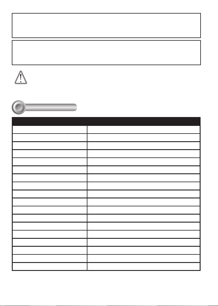
Specications
I
Model Name AE-235
LED Quantity 12 IR LEDs
IR Light Distance Approach To 80 ~ 100M
IR Light ON/OFF Photo Diode Sensor Control
Infrared Bean Angle 30° or 45 °
Power Input AC90~240V (+/-10%)
Rating Current 5 A
Heater Control 18°C (ON) / 28°C (OFF) & 0°C (ON) / 10°C (OFF)
Blower Control 35°C (ON) / 25°C (OFF)
Operation Temp. -20°C ~ +50°C
Environmental Storage Temp. -40°C ~ +50°C
Protection Level IP68 or IP44 with ventilation hole
Window Temper glass, 4mm thickness
Mounting Bracket Fully-cable Management
Construction Die-Cast Aluminum Alloy
Coating Ivory Powder & Stove Finish
Dimensions 425 (L) x 160 (W) x 165 (H) mm
Camera Space 275 (L) x 90 (W) x 100 (H) mm
Net Weight 5530 gm
2
Page 3

Physical description
II
English
11
12
3
2
1
1. Lens cap with heater 2. IR LEDs behind temper glass
3. IR board and IR board bracket 4. Thermostat switch
5. Day/Night trigger: controls the color/mono
mode switch for D/N cameras
7. Camera bracket 8. Heater
9. Power Supply Unit: AC90~240V power input,
DC12V output
11. Fuse holder: with a 250V/5A fuse 12. AC IN terminal block: AC 90~240V external
13. OUTPUT_1 spare terminal block: for AC 24V
or AC 90~240V camera use
15. VR: to adjust the Infrared LED activation level 16. Thermostat switch: turn on at 35°C and turn
17. Ground wire: to top cover
13
14
15 16
17
7
6
4
8
5
6. Universal IR control circuit board: to
10. Blower and blower bracket
14. OUTPUT_2: to power supply unit
9 10
control color/mono switching and IR on/off
synchronization
power input.
off at 25°C for blower
3
Page 4

AC input wiring: connect power lines to an external power cord.
Power cords
Connector Block
Brown: Line
Blue: Neutral
III
Interface Connections
Once a camera is installed, you can connect
the 12V DC phone jack connector to power the
camera.
Since the housing comes with a light sensor,
which controls when to turn into the night mode
and light the IR LEDs. Connect the red or orange
wire to the DI pin on the terminal block, and the
black wire to the Ground pin.
The following determines which wire (Red or
Orange) should be connected to the DI pin.
Red: If IR trigger signal is on the high position (+5V
DC), connect the Red and Black wires.
Orange: If IR trigger signal is on the Low position
(+0V DC), connect the Orange and Black wires.
DC 12V
Ground
DI
Yellow/Green: Earth
You should check the DI and Do settings on a web console in Conguration > Applications > DI and
DO. For example, if you connect the Red line to the DI, its normal status should be High.
4
Page 5

Configure the camera's IR cut filter
setting (if your camera comes with it) to
"Synchronize with digital input."
The configuration option can be found
in Configuration > Media > Image >
General settings > Day/Night settings >
IR cut lter.
Hardware Installation
IV
1. Loosen two screws on both sides of the camera bracket, and then adjust the position of
camera bracket by sliding it up and down.
2. Use the supplied L-type hex key wrench to x the camera on the camera bracket.
3. Connect the power cable and Ethernet cable to the camera.
Side View
L-type hex key wrench
2
1
Zoom ring
English
Focus ring
5
Page 6

4. Assemble the mounting bracket arm (A).(B).(C).
110.00mm
83.00mm
95.00mm
8.00mm
(B) (C)
(A)
Dimensions of Bracket Base
5. Feed the Ethernet cable and power cord from hole (D) on the bottom of the enclosure
through the mounting bracket arm.
6. Pan and tilt the enclosure to aim at the monitored area.
5
(D)
Ethernet cable
Power cord
6
7. Mount the enclosure to the mounting plate (C) with supplied four screws.
8. Use the supplied long screw to secure (C) with (B).
9. Use the supplied big screw to secure (B) with (A).
10. Use the supplied three screws to mount the enclosure to a desired location.
10
7
8
9
6
 Loading...