

Vivitek DU7295Z-WH, DU7295Z-BK User Manual

— i —
Copyright
This publication, including all photographs, illustrations and software, is protected under international
copyright laws, with all rights reserved. Neither this manual, nor any of the material contained herein, may
be reproduced without written consent of the author.
© Copyright 2019
Disclaimer
The information in this document is subject to change without notice. The manufacturer makes no
representations or warranties with respect to the contents hereof and specifically disclaims any implied
warranties of merchantability or fitness for any particular purpose. The manufacturer reserves the right to
revise this publication and to make changes from time to time in the content hereof without obligation of
the manufacturer to notify any person of such revision or changes.
Trademark Recognition
Kensington is a U.S. registered trademark of ACCO Brand Corporation with issued registrations
and pending applications in other countries throughout the world.
HDMI, the HDMI Logo, and High-Definition Multimedia Interface are trademarks or
registered trademarks of HDMI Licensing LLC in the United States and other countries.
HDBaseT™ and the HDBaseT Alliance logo are trademarks of the HDBaseT Alliance.
All other product names used in this manual are the properties of their respective owners and are
acknowledged.
Ver.: 1
DLP Projector—User’s Manual
— ii —
Important Safety Information
Important:
It is strongly recommended that you read this section carefully before using the projector. These
safety and usage instructions will ensure that you enjoy many years of safe use of the projector.
Keep this manual for future reference.
Symbols Used
Warning symbols are used on the unit and in this manual to alert you of hazardous situations.
The following styles are used in this manual to alert you to important information.
Note:
Provides additional information on the topic at hand.
Important:
Provides additional information that should not be overlooked.
Caution:
Alerts you to situations that may damage the unit.
Warning:
Alerts you to situations that may damage the unit, create a hazardous environment, or cause
personal injury.
Note:
As with any bright light source, do not stare into the beam, RG2 IEC 62471-5:2015
Throughout this manual, component parts and items in the OSD menus are denoted in bold font as in this
example:
“Push the Menu button on the remote control to open the Main menu.”
General Safety Information
Do not open the unit case. There are no user-serviceable parts in the unit. For servicing, contact
qualified service personnel.
Follow all warnings and cautions in this manual and on the unit case.
To avoid damage to eyes, do not look into the lens when the light source is on.
Do not place the unit on an unstable surface, cart, or stand.
Avoid using the system near water, in direct sunlight, or near a heating device.
Do not place heavy objects such as books or bags on the unit.
Notice
This product is intended for the adults who have the ability to operate this machine.
Please write down your projector model number and serial number and keep the information for
maintenance purposes in the future. Should the equipment be lost or stolen, the information could also be
used for the police report.
Model number:
Serial number:

Preface
– iii –
LASER WARNING
This symbol indicates that there is a potential hazard of eye exposure to laser
radiation unless the instructions are closely followed.
CLASS 3R LASER PRODUCT
This Laser Product is designated as Class 3R during all procedures of operation. LASER
LIGHT - AVOID DIRECT EYE EXPOSURE.
Do not point laser or allow laser light to be directed or reflected toward other people or reflective
objects .
Direct or scattered light can be hazardous to eyes and skin.
There is a potential hazard of eye exposure to laser radiation if the included instructions are not
followed.
Caution – use of controls or adjustments or performance of procedures other than those
specified herein may result in hazardous radiation exposure
Laser Parameters
Wavelength 450nm - 460nm (Blue)
Mode of operation Pulsed, due to frame rate
Pulse width 1.34ms
Pulse repetition rate 120Hz
Maximum laser energy 0.698mJ
Total internal power >100w
Apparent source size >10mm, at lens stop
Divergence >100 mili Radian
DLP Projector—User’s Manual
— iv —
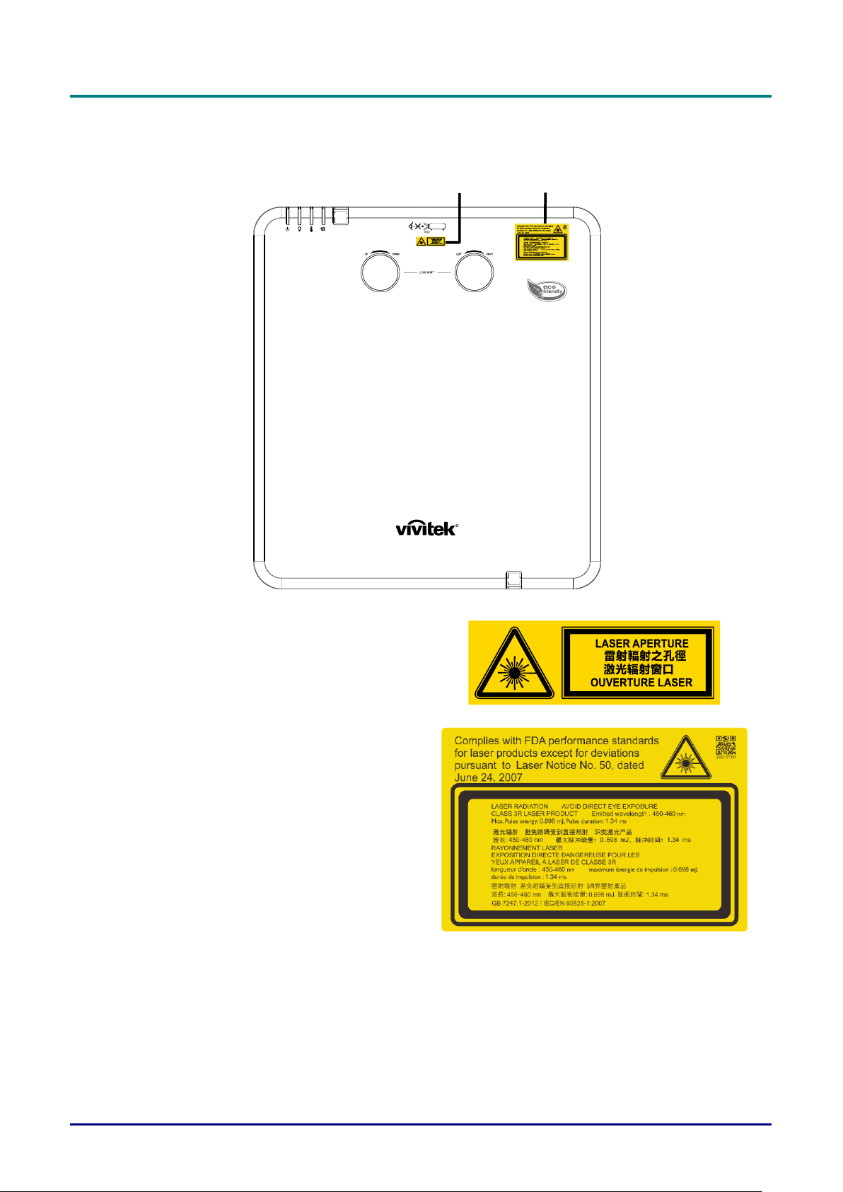
Product labels (DU70x Series)
Below drawing show the label’s location
1 2
1.
Hazard Warning Symbol and
Aperture Label
2.
Explanatory Label
Preface
– v –
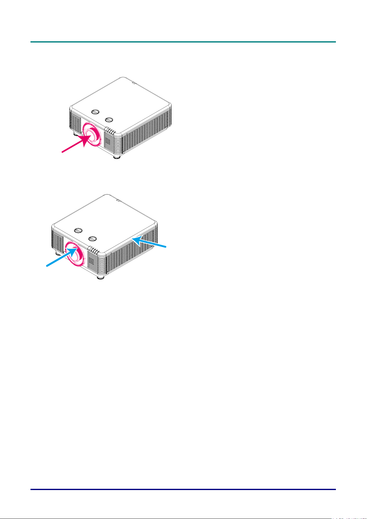
Location of laser aperture
Below drawing is the laser aperture location. Be careful not to let the eye see the light directly.
Laser aperture
Interlock switches
This machine has 2 (Top cover x 1, Lens x 1) Interlock switches to protect the laser light Leakage.
1. Will power-off the system individually when the top cover is removed.
2. Will power-off the system individually when the lens is removed or not install correctly.
DLP Projector—User’s Manual
— vi —
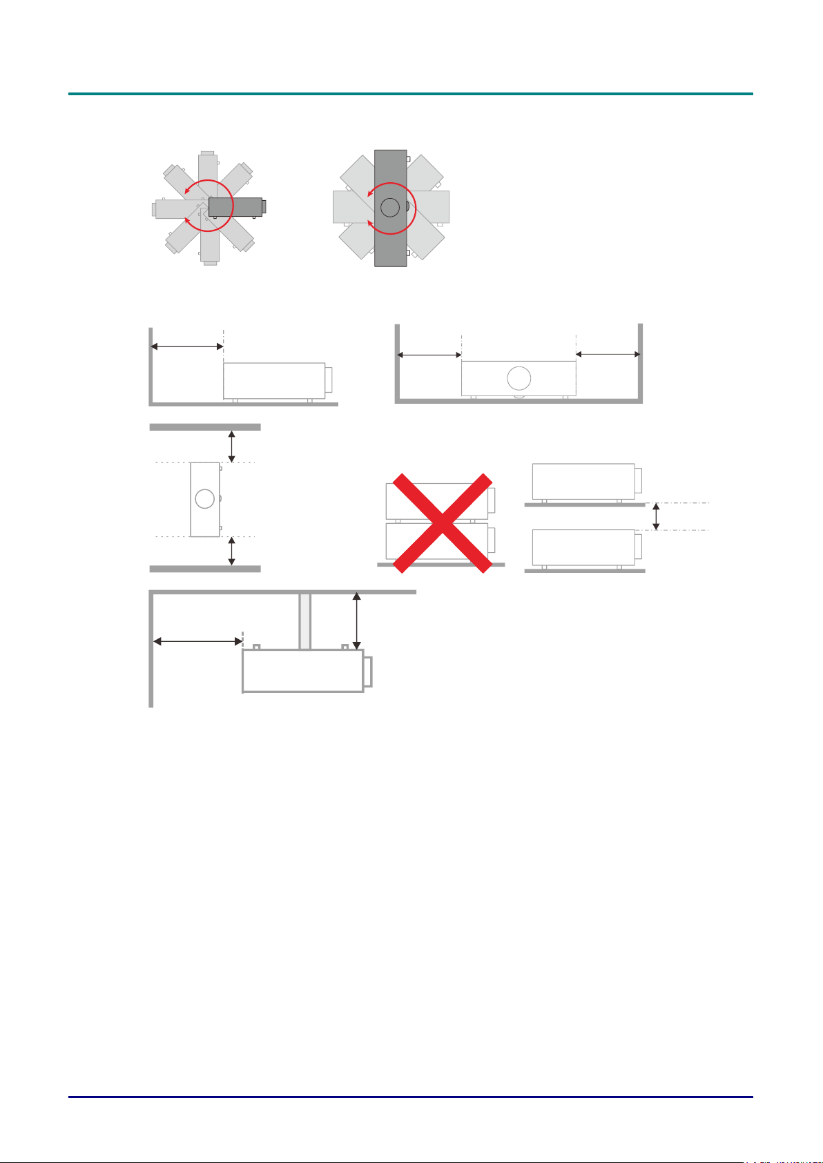
Projector Installation Notice
There is no limitation angle for projector installation.
Allow at least 50 cm clearance around the exhaust vent.
Ensure that the intake vents do not recycle hot air from the exhaust vent.
When operating the projector in an enclosed space, ensure that the surrounding air temperature
within the enclosure does not exceed operation temperature while the projector is running, and the
air intake and exhaust vents are unobstructed.
All enclosures should pass a certified thermal evaluation to ensure that the projector does not
recycle exhaust air, as this may cause the device to shutdown even if the enclosure temperature is
with the acceptable operation temperature range.
Minimum 500mm
(19.69 inch)
Minimum 500mm
(19.69 inch)
Minimum 500mm
(19.69 inch)
Minimum 500mm
(19.69 inch)
Minimum 300mm
(11.81 inch)
Minimum 100mm
(3.94 inch)
Minimum 500mm
(19.69 inch)
Minimum 500mm
(19.69 inch)

Preface
– vii –
Verify Installation Location
To supply power, the 3-blade (with earthing lead) socket should be used to ensure proper
grounding and equalized ground potential for all of the equipment in the Projector System.
The power code provided with the Projector should be used. In case of any missing item, other
qualified 3-blade (with earthing lead) power cord can be used as substitution; however, do not use
2-blade power cord.
Verify if the voltage is stable, grounded properly and there is no electricity leakage.
Measure total power consumption which should not higher the safety capacity and avoid safety
issue and short circuit.
Turn on Altitude Mode when located in high altitude areas
The projector can only be installed upright or inverted.
When installation the bracket, make sure the weight limit is not exceed and firmly secured.
Avoid installing near air conditioner duct or subwoofer.
Avoid installing at high temperature, insufficient cooling and heavy dust locations.
Keep your product away from fluorescent lamps (>1 Meter) to avoid malfunction
caused by IR interference
The VGA IN connector should be connected to the VGA IN port. Note that it should be inserted
tightly, with the screws on both sides securely fastened to ensure proper connection of the signal
wire for achieving optimal display effect.
The AUDIO IN connector should be connected to the AUDIO IN port and CANNOT be connected
to AUDIO OUT or other ports like BNC, RCA; otherwise, it will lead to mute output and even
DAMAGE the port.
Install the projector above 200cm to avoid damage.
The power cord and signal cable should be connected before power on the projector. During the
projector starting and operating process, DO NOT insert or remove the signal cable or the power
cord to avoid damaging the projector.
Cooling notes
Air outlet
Make sure the air outlet is 50cm clear of any obstruction to ensure proper cooling.
Air outlet location should not be in front of the lens of other projector to avoid causing illusions.
Keep the outlet at least 100cm away from the inlets of other projectors
The projector generates a massive amount of heat during use. The internal fan dissipates the heat
of the projector when shutting down, and such process may continue for a certain period. After the
project enters STANDBY MODE status, press the AC power button to turn off the projector and
remove the power cord. DO NOT remove the power cord during the shutdown process, as it may
cause damage to the projector. In the meantime, the delayed heat radiating will also affect the
service life of the projector. The shutdown process may vary depending on the model used.
Whatever the case may be, be sure to disconnect the power cord till after the projector enters the
STANDBY status.
Air inlet
Make sure there is no object blocking air input within 30 cm.
Keep the inlet away from other heat sources
Avoided heavy dust area

DLP Projector—User’s Manual
— viii —
Power Safety
Only use the supplied power cord.
Do not place anything on the power cord. Place the power cord where it will not be in the way of
foot traffic.
Remove the batteries from the remote control when storing or not in use for a prolonged period.
Cleaning the Projector
Unplug the power cord before cleaning. See Cleaning the Projector page 60.
Allow the light source to cool for about one hour.
Regulatory Warnings
Before installing and using the projector, read the regulatory notices in the Regulatory Compliance on
page 79.
Symbol Explanations
DISPOSAL: Do not use household or municipal waste collection services for
disposal of electrical and electronic equipment. EU countries require the use
of separate recycling collection services.
Special Care for Laser Beams!
Special care should be considered when DLP projectors and high power laser equipment are used in the
same room as.
Direct or indirect hit of a laser beam on to the projector lens can severely damage the Digital Mirror
Devices (DMD™).
Sun light Warning
Avoid using in direct sun light.
Sun light on the projector lens can severely damage the Digital Mirror Devices (DMD™).

Preface
– ix –
Main Features
Compatible with all major video standards including NTSC, PAL, and SECAM.
A high brightness rating allows for presentations in daylight or in lit rooms.
Flexible setup allows for front, rear projections.
Line-of-vision projections remain square, with advanced keystone correction for angled
projections.
Input source automatically detected.
High brightness for projection in just about any environment.
Supports resolutions up to WUXGA for clear and crisp images.
DLP® and BrilliantColor™ technologies from Texas Instruments.
Centered lens for easy installation.
Horizontal and vertical lens shift.
Built-in speaker with multiple audio-in and audio-out ports.
Network ready for integration and system administration via RJ45.
Sealed engine to minimizing the impact of dust and smoke.
Anti-theft security features include: Kensington security slot, security bar.
Built-in HDBaseT receiver. HDBaseT™ interface with support for distribution of HD video,
digital audio content RS232, RJ45 and IR function over standard CAT5e/6 LAN cable
Advanced laser phosphor light engine for superior brightness and color uniformity
Laser design deliveries up to 20,000 hours of operational time
About this Manual
This manual is intended for end users and describes how to install and operate the DLP projector.
Wherever possible, relevant information—such as an illustration and its description—has been kept on
one page. This printer-friendly format is both for your convenience and to help save paper, thereby
protecting the environment. It is suggested that you only print sections that are relevant to your needs.

DLP Projector—User’s Manual
— x —
Table of Contents
GETTING STARTED ..............................................................................................................................................1
PACKING CHECKLIST .............................................................................................................................................1
VIEWS OF PROJECTOR PARTS ................................................................................................................................2
Front-right View ...............................................................................................................................................2
Top view ..........................................................................................................................................................3
Side view—On-Screen Display (OSD) buttons and IO ...................................................................................4
Bottom view .....................................................................................................................................................6
REMOTE CONTROL PARTS .....................................................................................................................................8
REMOTE CONTROL OPERATING RANGE ............................................................................................................... 11
PROJECTOR AND REMOTE CONTROL BUTTONS .................................................................................................... 11
SETUP AND OPERATION .................................................................................................................................. 12
INSERTING THE REMOTE CONTROL BATTERIES .................................................................................................... 12
INSTALLING OR REMOVING THE OPTIONAL LENS ................................................................................................... 13
Installing the New Lens ................................................................................................................................ 13
Removing the Existing Lens From the Projector .......................................................................................... 14
STARTING AND SHUTTING DOWN THE PROJECTOR................................................................................................ 15
SETTING AN ACCESS PASSWORD (SECURITY LOCK) ............................................................................................. 17
ADJUSTING THE PROJECTOR LEVEL..................................................................................................................... 19
ADJUSTING PROJECTED IMAGE POSITION USING LENS SHIFT ............................................................................... 20
Adjusting the vertical image position ............................................................................................................ 20
Adjusting the horizontal image position ........................................................................................................ 21
Shift Range Diagram .................................................................................................................................... 21
ADJUSTING THE ZOOM, FOCUS AND KEYSTONE .................................................................................................... 22
ADJUSTING THE VOLUME .................................................................................................................................... 23
ON-SCREEN DISPLAY (OSD) MENU SETTINGS............................................................................................. 24
OSD MENU CONTROLS ...................................................................................................................................... 24
Navigating the OSD ...................................................................................................................................... 24
SETTING THE OSD LANGUAGE ............................................................................................................................ 25
OSD MENU OVERVIEW ....................................................................................................................................... 26
IMAGE MENU ...................................................................................................................................................... 29
Computer Menu ............................................................................................................................................ 30
Advanced Feature ........................................................................................................................................ 31
White Balance .............................................................................................................................................. 32
Color Manager .............................................................................................................................................. 33
Dynamic Black Settings ................................................................................................................................ 34
HDR Settings ................................................................................................................................................ 35
SETTINGS 1 MENU .............................................................................................................................................. 36
Keystone ....................................................................................................................................................... 37
Audio............................................................................................................................................................. 37
Advanced 1 Feature ..................................................................................................................................... 38
Advanced 2 Feature ..................................................................................................................................... 40
4 Corner ........................................................................................................................................................ 41
SETTINGS 2 MENU .............................................................................................................................................. 42
Light Setting .................................................................................................................................................. 43
Status............................................................................................................................................................ 44
Advanced 1 Feature ..................................................................................................................................... 45
Advanced 2 Feature ..................................................................................................................................... 58
MAINTENANCE AND SECURITY ...................................................................................................................... 60
CLEANING THE PROJECTOR ................................................................................................................................ 60
Cleaning the Lens ......................................................................................................................................... 60
Cleaning the Case ........................................................................................................................................ 60
Cleaning the Air Filter ................................................................................................................................... 61
REPLACING THE FILTER ...................................................................................................................................... 62
USING THE PHYSICAL LOCK ................................................................................................................................ 64
Using the Kensington Security Slot .............................................................................................................. 64
Using the Security Bar Lock ......................................................................................................................... 64

Preface
– xi –
TROUBLESHOOTING ........................................................................................................................................ 65
COMMON PROBLEMS AND SOLUTIONS ................................................................................................................. 65
TIPS FOR TROUBLESHOOTING ............................................................................................................................. 65
LED ERROR MESSAGES ..................................................................................................................................... 66
IMAGE PROBLEMS .............................................................................................................................................. 66
LIGHT SOURCE PROBLEMS ................................................................................................................................. 67
REMOTE CONTROL PROBLEMS ............................................................................................................................ 67
AUDIO PROBLEMS .............................................................................................................................................. 67
HAVING THE PROJECTOR SERVICED .................................................................................................................... 68
HDMI Q & A ...................................................................................................................................................... 69
SPECIFICATIONS ............................................................................................................................................... 70
SPECIFICATIONS ................................................................................................................................................. 70
PROJECTION DISTANCE VS. PROJECTION SIZE ..................................................................................................... 72
Projection Distance and Size Table ............................................................................................................. 72
TIMING MODE TABLE .......................................................................................................................................... 75
Table of Supported Frequency ..................................................................................................................... 75
Table of Supported Frequency For 3D mode ............................................................................................... 77
PROJECTOR DIMENSIONS ................................................................................................................................... 78
REGULATORY COMPLIANCE .......................................................................................................................... 79
FCC WARNING .................................................................................................................................................. 79
CANADA ............................................................................................................................................................. 79
SAFETY CERTIFICATIONS .................................................................................................................................... 79
APPENDIX I......................................................................................................................................................... 80
COMMUNICATION PARAMETER SETUP .................................................................................................................. 80
DLP Projector—User’s Manual
— 1 —
GETTING STARTED
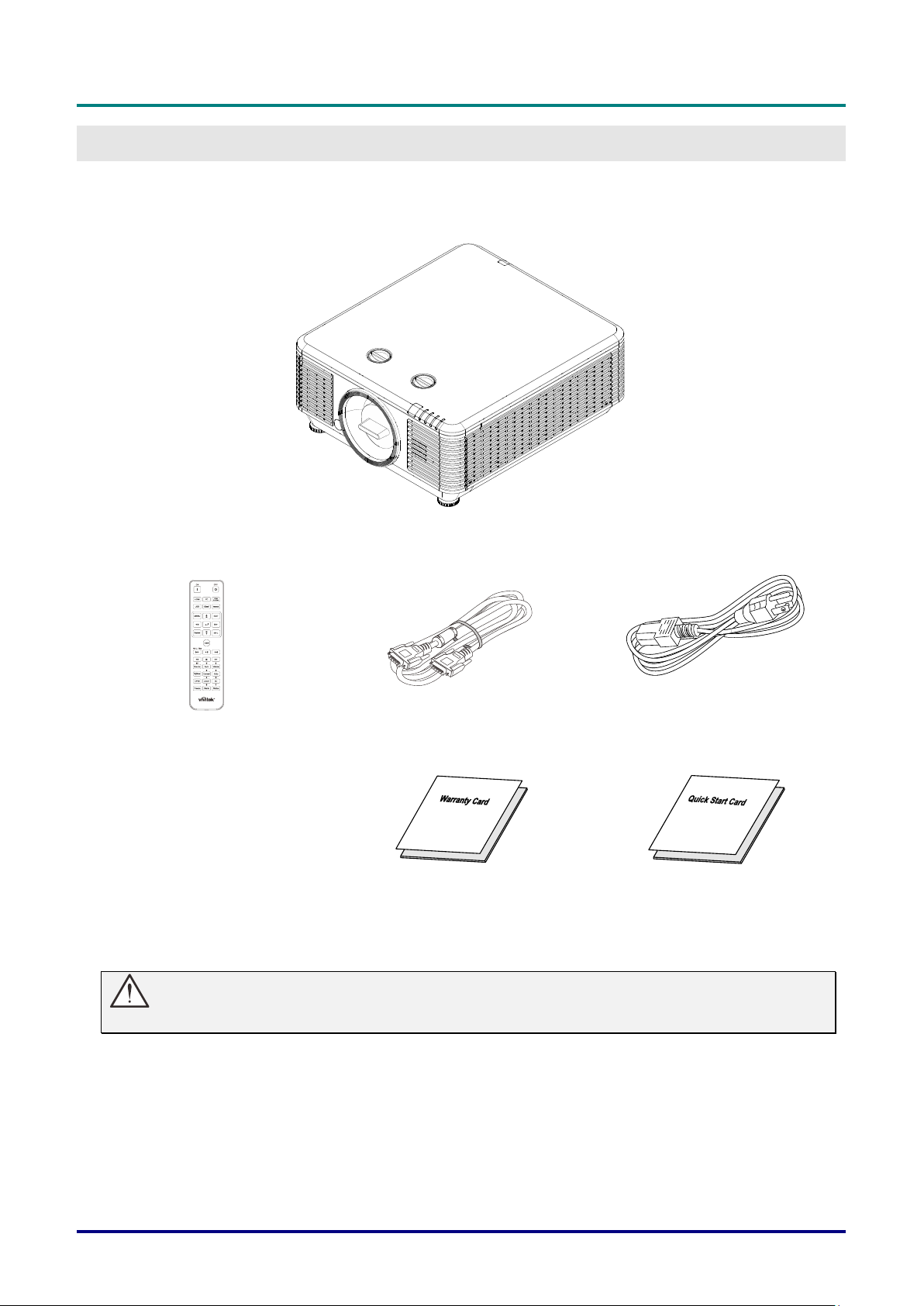
Packing Checklist
Carefully unpack the projector and check that the following items are included:
Projector
Remote Control
(Batteries Included)
VGA Cable (1.8m)
Power Cord (1.8m)
Warranty Card
Quick Start Guide
Contact your dealer immediately if any items are missing, appear damaged, or if the unit does not work. It is
recommend that you keep the original packing material should you ever need to return the equipment for
warranty service.
Caution:
Avoid using the projector in dusty environments.
DLP Projector—User’s Manual
— 2 —
Views of Projector Parts
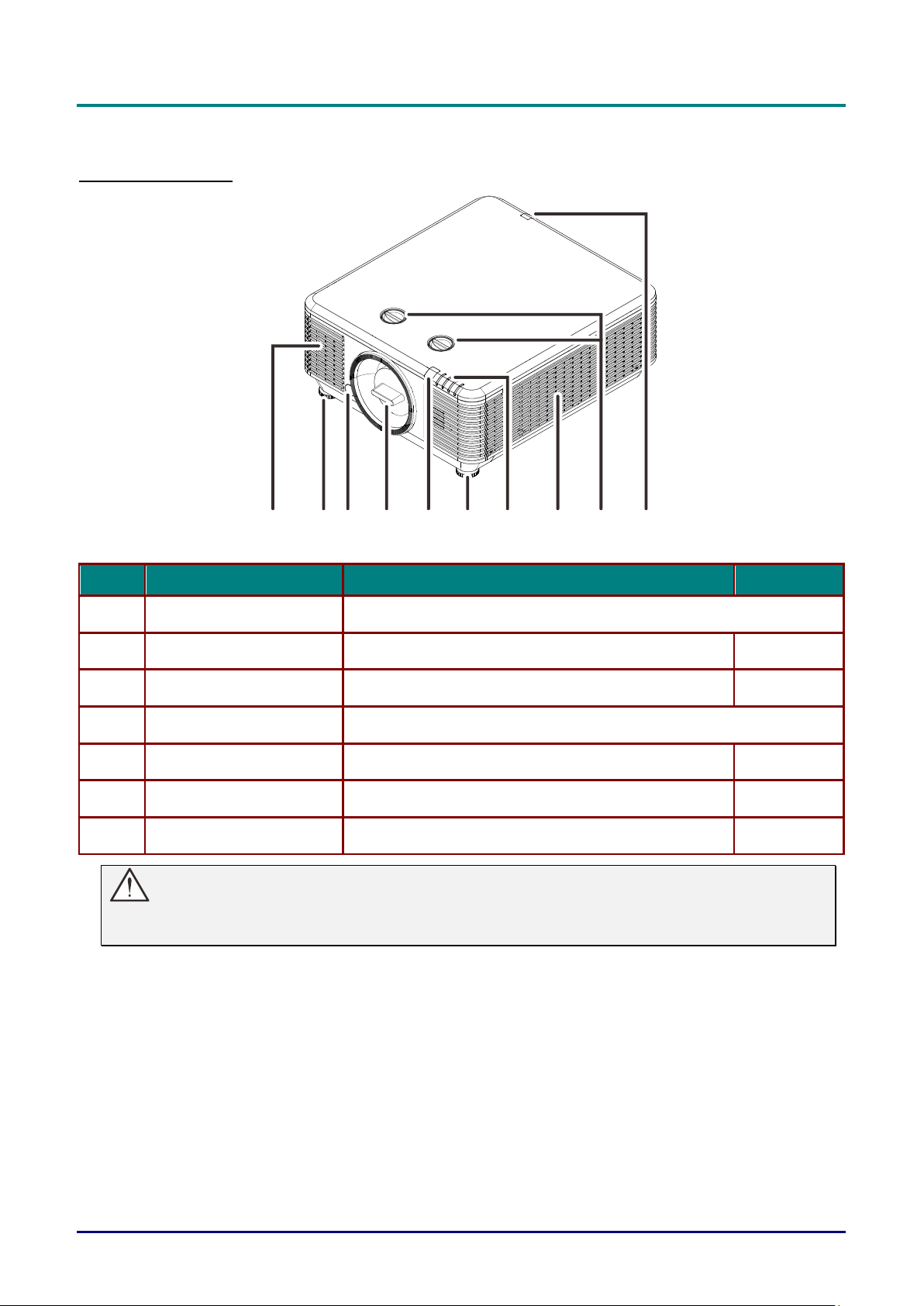
Front-right View
1 2 3 4 2 1
7
5 6 5
ITEM
LABEL
DESCRIPTION
SEE PAGE:
1.
Vent
Cool air intake.
2.
Tilt Adjuster
Rotate adjuster lever to adjust angle position.
19
3.
Lens Release Button
For release Lens.
14
4.
Anti-dust cap
Anti-dust cap
5.
IR Receiver
Receives IR signal from remote control.
7
6.
LEDs
Displays the projector status.
3
7.
Lens Shift
Adjusts the image position.
20
Important:
Ventilation openings on the projector allow for good air circulation, which keeps the projector light
source cool. Do not obstruct any of the ventilation openings.
DLP Projector—User’s Manual
– 3 –
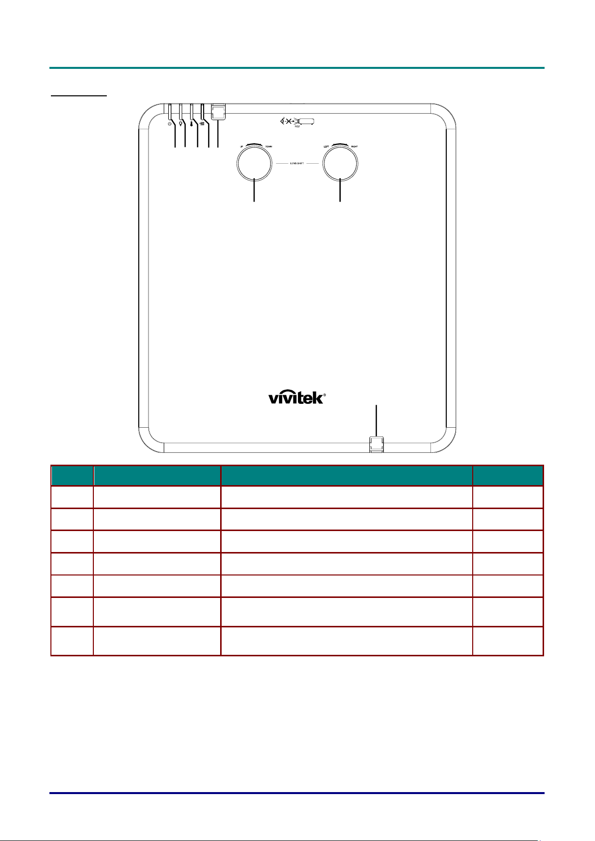
Top view
1 2 34 5
6
7
5
ITEM
LABEL
DESCRIPTION
SEE PAGE:
1.
Power LED
Display the power on/off sequence status.
66
2.
Light source LED
Display the light source status.
66
3.
Temp LED
Display the thermal status.
66
4.
Filter LED
Display the filter replacing warning message.
66
5.
IR Receiver
Receives IR signal from remote control.
7
6.
Vertical Lens Shift
(UP / DOWN)
Adjusts the image position vertically.
20
7.
Horizontal Lens Shift
(LEFT / RIGHT)
Adjusts the image position horizontally.
21
DLP Projector—User’s Manual
— 4 —
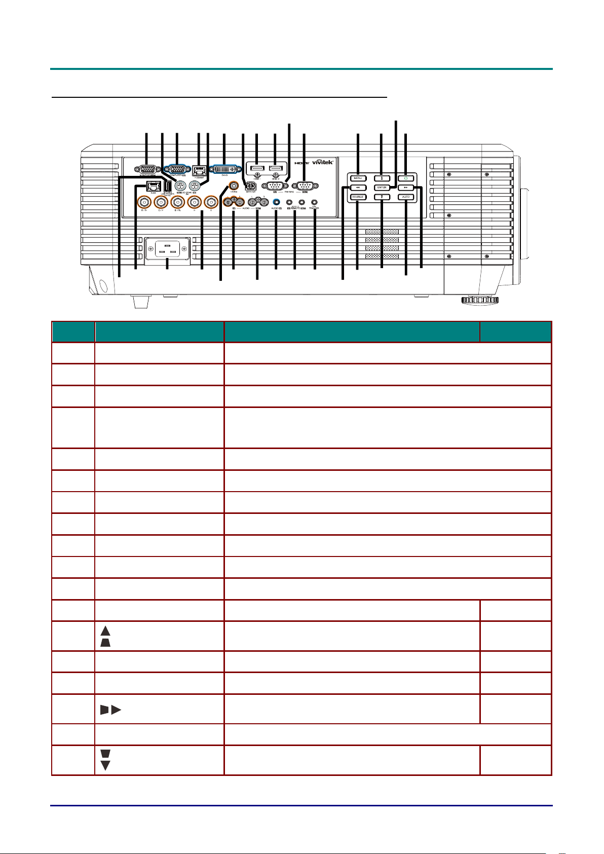
Side view—On-Screen Display (OSD) buttons and IO
7
8
9
10
11
12
13
14
15
16
17
18
19
20
212223
24
25
26
27
28
29
30
1
2 3 4
5
6
ITEM
LABEL
DESCRIPTION
SEE PAGE:
1.
MONITOR OUT
Connect an RGB cable to a display.
2.
3D-SYNC OUT (5V)
Connect 3D IR glasses receiver unit.
3.
COMPUTER IN
Connect an RGB cable from a computer or a video enabled device.
4.
HDBaseT
Connect Cat5e/Cat6 cable from HDBaseT TX Box (VIDEO
EXTENDER) for HDBaseT signal received.
Note: HDBaseT cable suggest use cat6 type cable.
5.
3D-SYNC IN (5V)
Connect 3D-sync in cable from a computer or an enabled device.
6.
DVI-D
Connect the DVI CABLE to display.
7.
SERVICE
For service personnel only.
8.
HDMI 1
Connect the HDMI cable from an HDMI device.
9.
HDMI 2
Connect the HDMI cable from an HDMI device.
10.
RS-232C IN
Connects RS-232 serial port cable for remote control.
11.
RS-232C OUT
Connects to another projector (same model) for RS-232 control.
12.
MENU
Opens and exits OSD menus.
24
13.
Navigates and changes settings in the OSD.
Quick Menu – For Vertical Keystone.
24
14.
ENTER
Enter or confirm highlighted OSD menu item.
24
15.
Power
Turn the projector on or off.
15
16.
Navigates and changes settings in the OSD.
Quick Menu – For Horizontal Keystone.
24
17.
AUTO
Optimizes image size, position, and resolution.
18.
Navigates and changes settings in the OSD.
Quick Menu – For Vertical Keystone.
24

DLP Projector—User’s Manual
– 5 –
ITEM
LABEL
DESCRIPTION
SEE PAGE:
19.
SOURCE
Enter the Source menu.
20.
Navigates and changes settings in the OSD.
Quick Menu – For Horizontal Keystone.
24
21.
12V TRIGGER
When connected to the screen through a commercially available
cable, the screen deploys automatically on start up of the projector.
The screen retracts when the projector is powered off (see notes
below).
22.
WIRE REMOTE IN / OUT
Connect the wire remote from remote control to the projector for wire
remote control.
Connect "WIRE REMOTE OUT" to another projector (same model)
"WIRE REMOTE IN" for serial control.
23.
AUDIO IN
Connect an AUDIO cable from the audio device.
24.
AUDIO OUT L/R
Connect an AUDIO cable for audio loop through.
25.
AUDIO IN L/R
Connect the audio cables from an audio device for VIDEO audio input.
26.
VIDEO
Connect the composite cable from a video device.
27.
BNC
Connect a BNC cable from a computer.
28.
AC IN
Connect the POWER cable.
29.
RJ45
Connect a LAN cable from Ethernet.
30.
USB POWER (5V/1.5A)
Connect a USB cable for USB host.
Note: Support 5V/1.5A output as long as the projector Power On.
Note:
To use this feature, you must plug in the connector before turn on/off the projector.
Screen controllers are supplied and supported by screen manufacturers.
Do not use this jack for anything other than intended use.
Warning:
As a safety precaution, disconnect all power to the projector and connecting devices before making
connections.
DLP Projector—User’s Manual
— 6 —
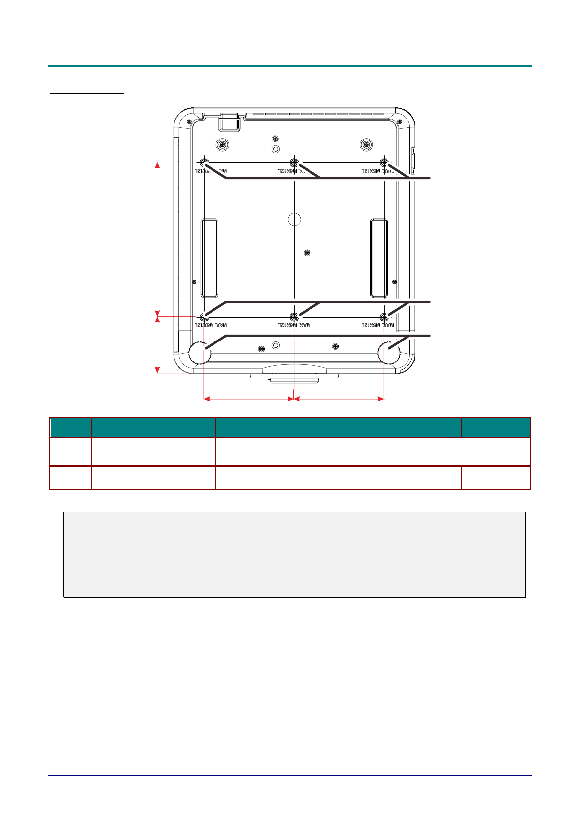
Bottom view
300mm
[11.81"]
110mm
[4.33"]
175mm
[6.89"]
175mm
[6.89"]
1
1
2
ITEM
LABEL
DESCRIPTION
SEE PAGE:
1.
Ceiling Mount Holes
Contact your dealer for information on mounting the projector on a
ceiling.
2.
Tilt Adjustor
Rotate adjuster lever to adjust angle position.
19
Note:
When installing, ensure that you use only UL Listed ceiling mounts.
For ceiling installations, use approved mounting hardware and M6 screws with a maximum screw
depth of 12mm (0.47 inch).
The construction of the ceiling mount must be of a suitable shape and strength. The ceiling mount
load capacity must exceed the weight of the installed equipment, and as an additional precaution
be capable of withstanding three times the weight of the equipment over a period of 60 seconds.

DLP Projector—User’s Manual
– 7 –
Reference drawings for stand
Please hire an installation service provider (for a fee) for the design and manufacture of a customized
stand to be used for portrait projection. Please ensure that the design complies with the following
conditions:
• Use the 6 screw holes at the back of the projector to secure it to the stand.
Screw hole center dimension: 300 × 350 (pitch = 175) mm
Screw hole dimension on the projector: M6 with the maximum depth 12 mm
• Horizontal adjustment mechanism (for example, bolts and nuts in 4 places)
• Please design the stand so that it does not easily topple over.
The drawing showing the dimensional requirements is not an actual stand design drawing.
[Side View]
[Front View]
Horizontal adjuster
Air exhaust
Air intake
Air intake
Air intake
300mm
[11.81"]
110mm
[4.33"]
1
7
5
m
m
[6
.8
9
"]
1
7
5
m
m
[6
.8
9
"]
DLP Projector—User’s Manual
— 8 —
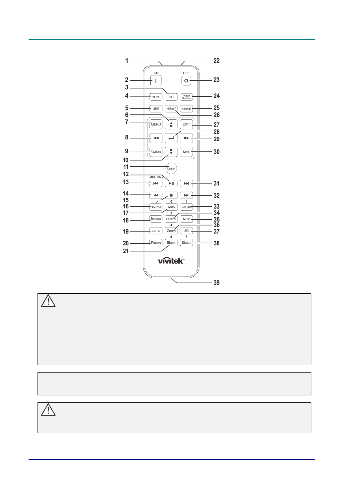
Remote Control Parts
Important:
1. Avoid using the projector with bright fluorescent lighting turned on. Certain high-frequency
fluorescent lights can disrupt remote control operation.
2. Be sure nothing obstructs the path between the remote control and the projector. If the path
between the remote control and the projector is obstructed, you can bounce the signal off certain
reflective surfaces such as projector screens.
3. The buttons and keys on the projector have the same functions as the corresponding buttons on
the remote control. This user’s manual describes the functions based on the remote control.
Note:
Complies with FDA performance standards for laser products except for deviations pursuant to
Laser Notice No. 50, dated June 24, 2007
Caution:
Use of controls, adjustments or performance of procedures other than those specified herein
may result in hazardous laser light exposure.

DLP Projector—User’s Manual
– 9 –
ITEM
LABEL
DESCRIPTION
SEE PAGE:
1.
IR Transmitter
Transmits signals to projector.
2.
Power On
Turns the projector on.
15
3.
PC
Displays the PC source selection.
4.
HDMI
Displays the HDMI1/HDMI 2/DVI source selection (toggle).
5.
USB
NA
6.
Navigates and changes settings in the OSD.
Quick Menu – For Vertical Keystone.
24
7.
MENU
Opens the OSD.
24
8.
Navigates and changes settings in the OSD.
Quick Menu – For Horizontal Keystone.
24
9.
Keystone
Opens the Keystone menu.
10.
Navigates and changes settings in the OSD.
Quick Menu – For Vertical Keystone.
24
11.
Laser
Press to operate the on-screen pointer. DO NOT POINT IN EYES.
12.
NA
13.
NA
14.
NA
15.
NA
16.
Source/ID
Alternate input source.
Combo key function for Remote Control customer code
settings (Press ID button + Number for 3 seconds).
24
17.
Auto/0
Auto adjustment for frequency, phase, and position.
Number for Remote ID setting used.
24
18.
Brightness
Displays the brightness setting bar.
19.
Lamp
Displays the light source selections.
20.
Freeze
Freezes/unfreezes the on-screen picture.
21.
Blank/6
Makes the screen blank.
Number for Remote ID setting used.
22.
Laser
Use as on-screen pointer. DO NOT POINT IN EYES.
23.
Power Off
Turns the projector off.
15
24.
Video/S-Video
Displays the Video source selection.
25.
Network
Open the OSD Network menu.
26.
HDBaseT
Displays the HDBaseT source selection.
27.
EXIT
Return to last OSD page.
28.
Enters and confirms settings in the OSD.
24
29.
Navigates and changes settings in the OSD.
Quick Menu – For Horizontal Keystone.
24
30.
MHL
NA
31.
NA
32.
NA
DLP Projector—User’s Manual
— 10 —
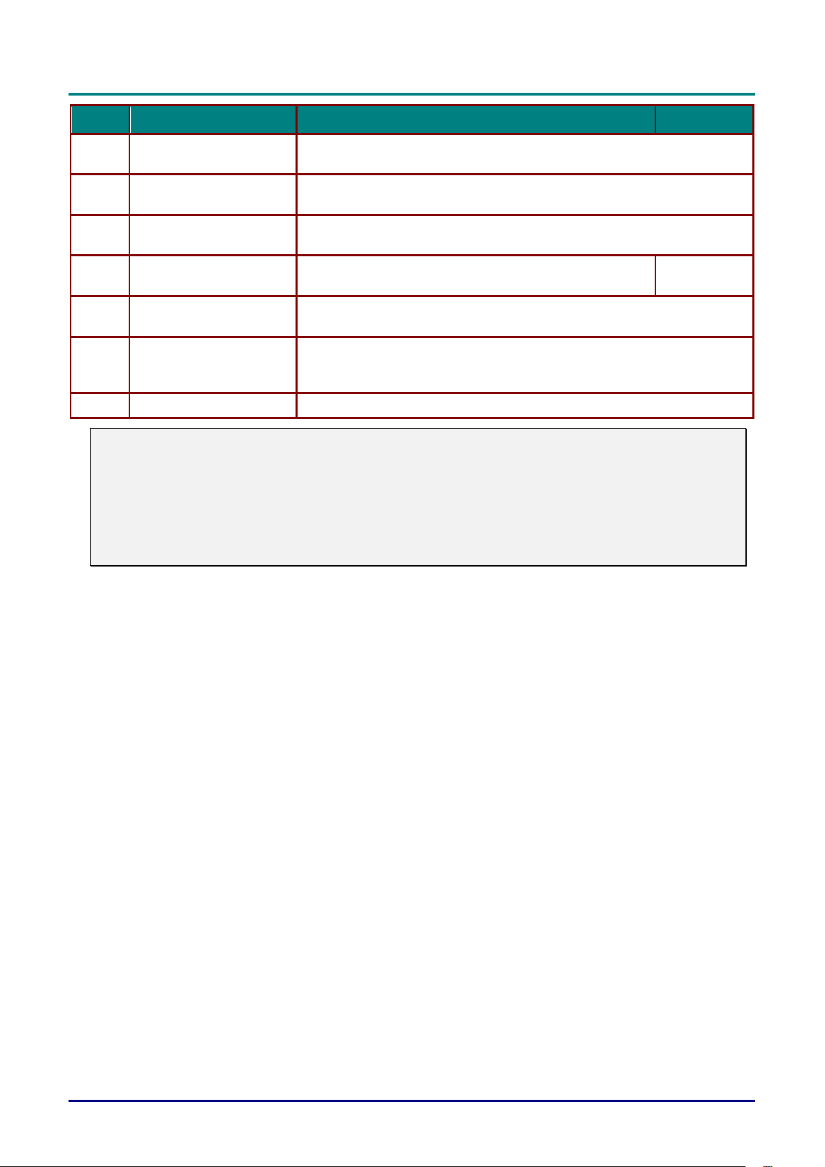
ITEM
LABEL
DESCRIPTION
SEE PAGE:
33.
Volume/1
Displays the Volume setting bar.
Number for Remote ID setting used.
34.
Contrast/2
Displays the Contrast settings bar.
Number for Remote ID setting used.
35.
Mute/3
Mutes the built-in speaker.
Number for Remote ID setting used.
36.
Zoom/4
Displays the digital zoom settings bar.
Number for Remote ID setting used.
22
37.
3D/5
Open the OSD 3D Setting menu.
Number for Remote ID setting used.
38.
Status/7
Opens the OSD Status menu (the menu only opens when an input
device is detected).
Number for Remote ID setting used.
39.
Wired Jack
Connect wire remote to the projector.
Note:
Remote Combo Key Settings:
ID+0: Reset Remote Control customer code to default settings.
ID+1: Set Remote Control customer code to "1".
~
ID+7: Set Remote Control customer code to "7".
Projector also need setting ID for unique control. Projector ID settings see page 45.

DLP Projector—User’s Manual
– 11 –
Remote Control Operating Range
The remote control uses infrared transmission to control the projector. It is not necessary to point the
remote directly at the projector. Provided you are not holding the remote perpendicular to the sides or the
rear of the projector, the remote will function well within a radius of about 7 meters (23 feet) and 15
degrees above or below the projector level. If the projector does not respond to the remote control, move a
little closer.
Projector and Remote Control Buttons
The projector can be operated using the remote control or the buttons on the top of the projector. All
operations can be carried out with the remote control; however, the buttons on the projector are limited in
use.
DLP Projector—User’s Manual
— 12 —
SETUP AND OPERATION
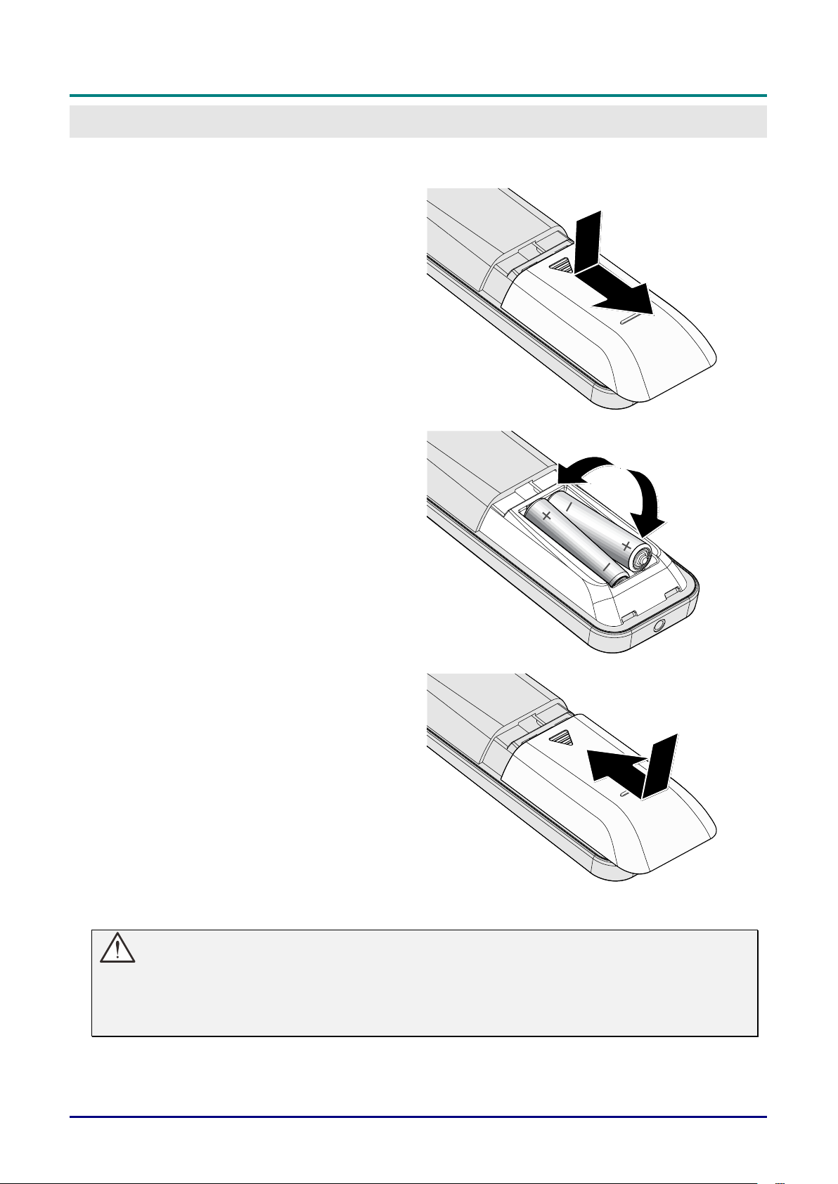
Inserting the Remote Control Batteries
1.
Remove the battery compartment
cover by sliding the cover in the
direction of the arrow.
2.
Insert the battery with the positive
side facing up.
3.
Replace the cover.
Caution:
1. Only use AAA batteries (Alkaline batteries are recommended).
2. Dispose of used batteries according to local ordinance regulations.
3. Remove the batteries when not using the projector for prolonged periods.
DLP Projector—User’s Manual
– 13 –
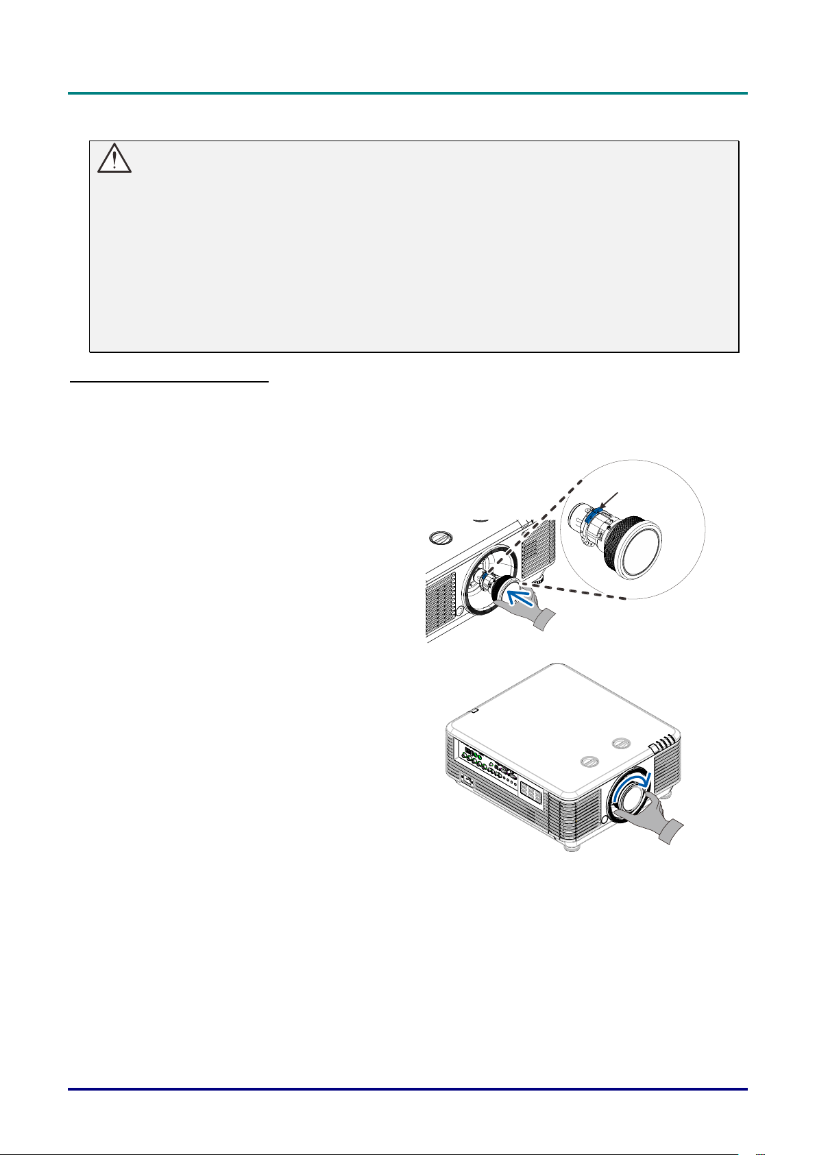
Installing or Removing the Optional Lens
Caution:
Do not shake or place excessive pressure on the projector or the lens components as the
projector and lens components contain precision parts.
Before removing or installing the lens, be sure to turn off the projector, wait until the cooling fans
stop, and turn off the main power switch.
Do not touch the lens surface when removing or installing the lens.
Keep fingerprints, dust or oil off the lens surface.
Do not scratch the lens surface.
Work on a level surface with a soft cloth under it to avoid scratching.
If you remove and store the lens, attach the lens cap to the projector to keep off dust and dirt.
Installing the New Lens
Remove both end caps from the lens.
Removal of the Anti-dust cap before inserting a lens for the first time.
1.
Align the flange and correctly
position at the 11 o’clock position as
shown in the picture.
Flange
2.
Rotate the lens clockwise until you
feel it click into place.

DLP Projector—User’s Manual
— 14 —
Removing the Existing Lens From the Projector
1.
Push the LENS RELEASE button to
the unlock position.
2.
Grasp the lens.
3.
Rotate the lens counterclockwise.
The existing lens will be
disengaged.
4.
Pull out the existing lens slowly.
DLP Projector—User’s Manual
– 15 –
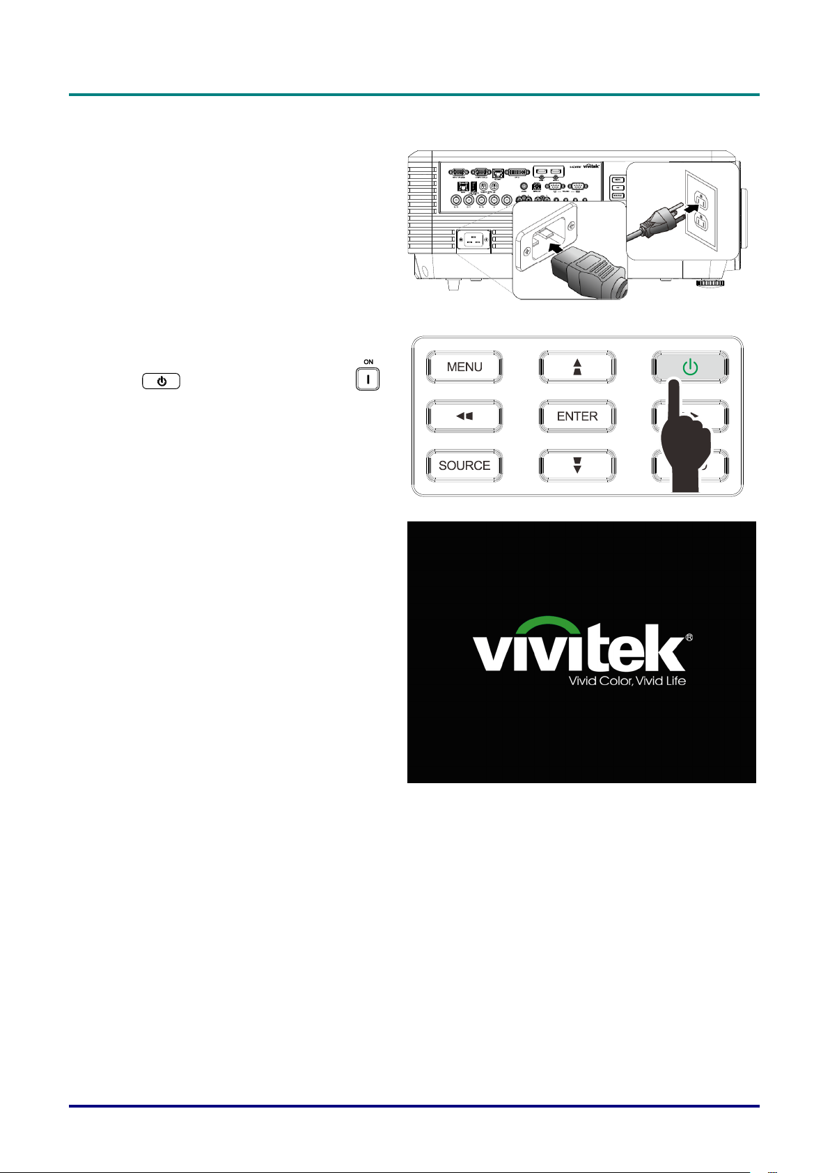
Starting and Shutting down the Projector
1.
Securely connect the power cord and
signal cable. When connected, the power
led will flash green to solid green.
2.
Turn on the light source by pressing
“ ” button on the projector or “ ”
on the remote control.
The PWR LED will now flash green.
The startup screen will display in
approximately 30 seconds. The first time
you use the projector, you can select
your preferred language from quick menu
after the startup screen display. (See
Setting the OSD Language on page 25)
See Setting an Access Password
(Security Lock) on page 17 if security lock
is enabled.

DLP Projector—User’s Manual
— 16 —
3.
If more than one input device is
connected, press the SOURCE button
and use ▲▼ to scroll among devices.
(Component is supported through the
RGB to Component adapter.)
HDMI 1: High-Definition Multimedia Interface
compatible
HDMI 2: High-Definition Multimedia Interface
DVI: DVI
VGA: Analog RGB
DVD input YCbCr/ YPbPr, or HDTV input
YPbPr via D-sub connector
BNC: Analog RGB
Composite Video: Traditional composite video
HDBaseT: Digital Video trough the HDBaseT
transmitter
Note:
It is recommended to use a certified TX box (VIDEO
EXTENDER) – Rextron (EVBMN-110L38) for the
HDBaseT function and there is no guarantee of full
response when other brands of TX box are used..
Using a single HDBaseT CAT5e/6 cable, the projector
supports an HDBaseT connection distances to
100m/328ft.
4.
When the “Power Off? /Press Power
again” message appears, press the
POWER button. The projector turns off.
Caution:
Do not unplug the power cord until the POWER LED stops flashing – indicating the projector has
cooled down.
DLP Projector—User’s Manual
– 17 –
Setting an Access Password (Security Lock)
You can use the four (arrow) buttons to set a password and prevent unauthorized use of the projector.
When enabled, the password must be entered after you power on the projector. (See Navigating the OSD
on page 24 and Setting the OSD Language on page 25 for help on using OSD menus.)
Important:
Keep the password in a safe place. Without the password, you will not be able to use the projector.
If you lose the password, contact your reseller for information on clearing the password.
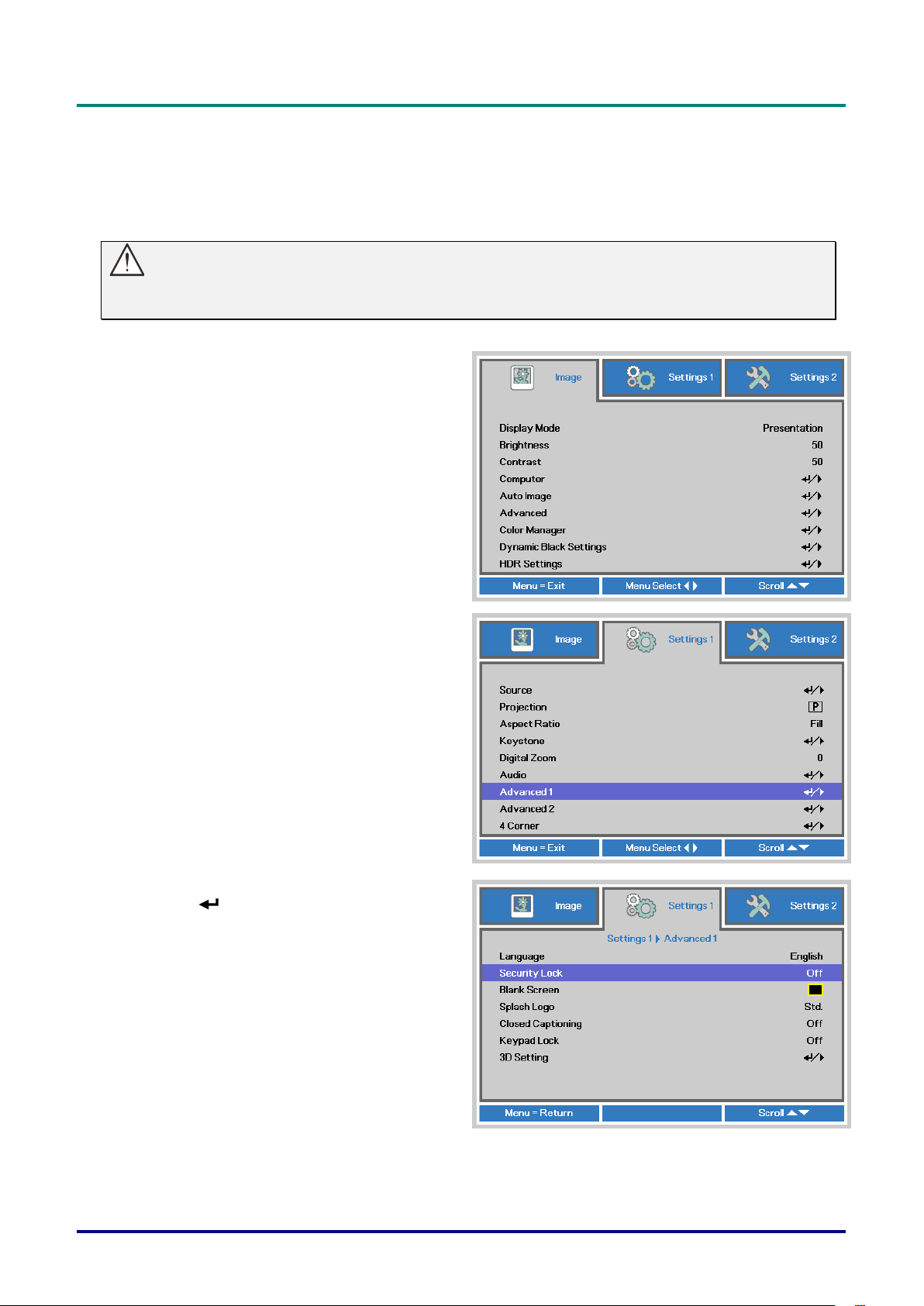
1.
Press the MENU button to open the
OSD menu.
2.
Press the cursor ◄► button to move to
the Settings 1 menu, press the cursor
▲▼ button to select Advanced 1.
3.
Press (Enter) / ► to enter the
Advanced 1 sub menu. Press the
cursor ▲▼ button to select Security
Lock.
4.
Press the cursor ◄► button to enter
and enable or disable security lock
function.
A password dialog box automatically
appears.
DLP Projector—User’s Manual
— 18 —
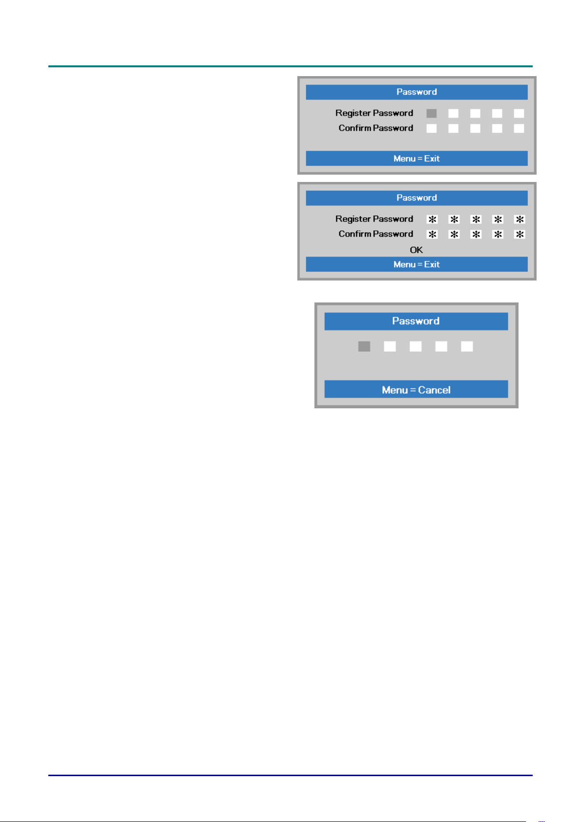
5.
You can use the cursor buttons
▲▼◄►
either on keypad or IR remote control
for password entry. You can use any
combination including the same arrow
five times, but not less than five.
Press the cursor buttons in any order to
set the password. Push the MENU
button to exit the dialog box.
6.
The password confirm menu appears
when user presses the power-on key in
case the Security Lock is enabled.
Enter the password in the order you set
it at step 5. In case you forget the
password, please contact the service
center.
The service center will validate the
owner and help reset the password.
 Loading...