

Page 1
User’s Manual
Page 2

Contents
COPYRIGHT INFORMATION 5
y Copyright 5
y Disclaimer 5
y About this manual 5
Start using the projector - Adjustments 23
y Connecting to AC Power 23
y Turning on the Power 23
y Changing the OSD Language 24
y Adjusting the Picture Orientation 24
y Lens Adjustments 25
IMPORTANT SAFETY INSTRUCTIONS 6
y DISPOSAL OF OLD ELECTRICAL AND ELECTRONIC EQUIPMENT 7
y Important Recycle Instructions: 7
INTRODUCTION 8
y About This Manual 8
y Description, Features and Benefits 8
y Parts List 9
CONTROLS AND FUNCTIONS 10
y D8300 at a Glance 10
y I/O Panel 11
y KEYPAD 12
y To install batteries in the remote control 14
y Range of effective remote control signal reception 14
Installation Considerations 15
y Ambient Light 15
y Throw Distance 15
y Modes of installation 15
y Allow at least 50 cm clearance around the exhaust vent. 16
y Do not tilt the projector more than 15 degrees. 17
y Other Considerations 17
Lens Shift 18
Start using the projector - Operation 26
y Selecting An Input Source 26
y Selecting an Aspect Ratio 26
y Using the OSD 26
Start using the projector - OSD Introduction 27
y OSD Menu Tree 27
y OSD Introduction - MAIN 28
y OSD Introduction - ADVANCE 30
y OSD Introduction - SYSTEM 33
y OSD Introduction - CONTROL 34
y OSD Introduction - LANGUAGE 35
y OSD Introduction - SERVICE 36
Change Lamp 38
y To replace the projector lamp 38
LED Status 40
y POWER 40
y ISSUE 40
SPECIFICATIONS 41
y Optical 41
y Electrical 41
y Physical 41
y Vertical Lens Shift 18
y Horizontal Lens Shift 18
Connecting the projector to other devices. 19
y HDMI Connection 19
y 12V Trigger connection 20
y IR Input connection 20
y S-VIDEO, VIDEO connection 21
y COMPONENT connection 21
y RS-232 Controller Connection 22
SERIAL INTERFACE SPECIFICATIONS 42
y Transfer Specifications 42
y RS-232 Commands 42
y IR Codes and Key names 42
y Operations Commands 43
Dimensions 46
Supported Timings 47
Projection Distance and Screen Size 48
Page 3

DLP Projector - User’s Manual
COPYRIGHT INFORMATION
Copyright
This publication, including all photographs, illustrations and software, is protected under international copyright laws,
with all rights reserved. Neither this manual, nor any of the material contained herein, may be reproduced without written consent of the manufacturer. The Vivitek logo is a trademark of “Vivitek Corporation.” © Copyright 2012
Disclaimer
The information in this document is subject to change without notice. The manufacturer makes no representations or
warranties with respect to the contents hereof and specifically disclaims any implied warranties of merchantability or
fitness for any particular purpose. The manufacturer reserves the right to revise this publication and to make changes
from time to time in the content here without obligation of the manufacturer to notify any person of such revision or
changes.
About this manual
This manual is intended for end users and describes how to install and operate the DLP projector. Wherever possible,
relevant information such as an illustration and its description has been kept on one page. This printer-friendly format is
both for your convenience and to help save paper, thereby protecting the environment. It is suggested that you only print
sections that are relevant to your needs.
5
Page 4
DLP Projector - User’s Manual
DLP Projector - User’s Manual
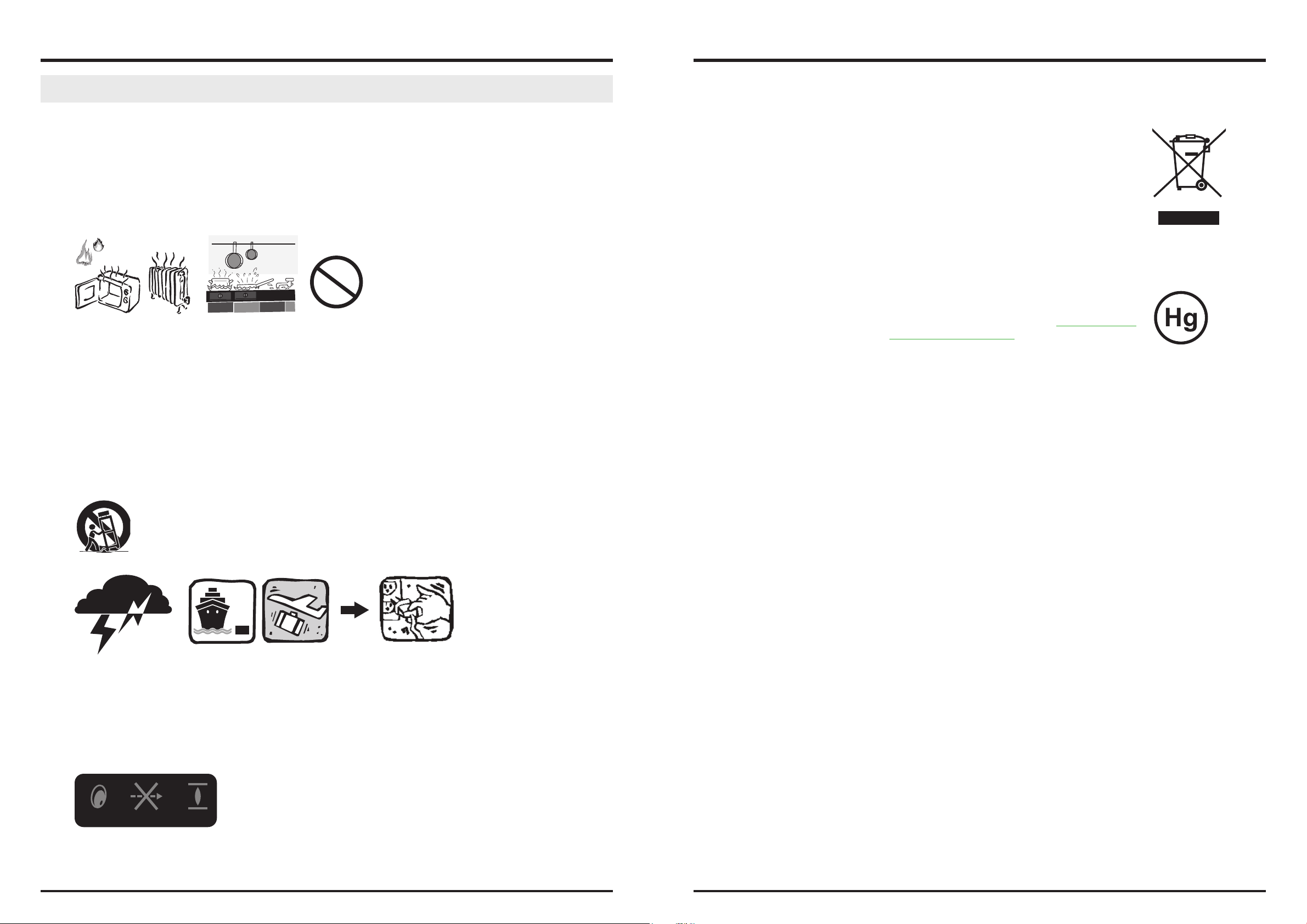
IMPORTANT SAFETY INSTRUCTIONS
Thank you for your purchase of this quality product! For best performance, please read this manual carefully as it is your
guide through the menus and operation.
1. Read and Keep these instructions.
2. Heed all warnings.
3. Follow all instructions.
4. Do not use this apparatus near water. and not install near any heat sources such as radiators, heat registers, stoves, or
other apparatus (including amplifiers) that produce heat.
5. Clean only with a dry cloth.
6. Do not block any of the ventilation openings. Install in accordance with the manufacturer’s instructions.
7. Do not defeat the safety purpose of the polarized or grounding type plug. A polarized plug has two blades with one
wider than the other. A grounding type plug has two blades and a third grounding prong. The wide blade or the third
prong is provided for your safety. When the provided plug does not fit into your outlet, consult an electrician for the
replacement of the obsolete outlet.
DISPOSAL OF OLD ELECTRICAL AND ELECTRONIC EQUIPMENT
(Applicable throughout the European Union and other European countries with separate collection programs)
This symbol found on your product or on its packaging, indicates that this product should not be
treated as household waste when you wish to dispose of it. Instead, it should be handed over to
an applicable collection point for the recycling of electrical and electronic equipment. By ensuring
this product is disposed of correctly, you will help prevent potential negative consequences to the
environment and human health, which could otherwise be caused by inappropriate disposal of this
product. The recycling of materials will help to conserve natural resources. This symbol is only valid
in the European Union. If you wish to discard this product, please contact your local authori-ties or
dealer and ask for the correct method of disposal.
Important Recycle Instructions:
Lamp(s) inside this product contain mercury. This product may contain other electronic waste that
can be hazardous if not disposed of properly. Recycle or dispose in accordance with local, state, or
federal Laws. For more information, contact the Electronic Industries Alliance at WWW.EIAE.ORG. For
lamp specific disposal information check WWW.LAMPRECYCLE.ORG.
8. Protect the power cord from being walked on or pinched particularly at plugs, convenience receptacles and the point
where they exit from the apparatus.
9. Only use the attachments/accessories specified by the manufacturer.
10. Use only with a cart, stand, tripod, bracket or table specified by the manufacturer or sold with the apparatus. When a
cart is used, use caution when moving the cart/apparatus to avoid injury from tip-over.
11. Unplug this apparatus during lightning storms or when unused for long periods of time.
12. Refer all servicing to qualified service personnel. Servicing is required when the apparatus has been damaged in any
way, such as power supply cord or plug is damaged, liquid has been spilled or objects have fallen into the ap-paratus,
the apparatus has been exposed to rain or moisture, does not operate normally, or has been dropped.
13. The +12V trigger only outputs 12V DC signal for triggering. Do not connect to any other power input or output. This
could cause damage to this unit.
14. Keep the packing material in case the equipment should ever need to be shipped.
15. Never look into the lens when the projector is on.
AVOID EYE CONTACT TO THE LIGHT
6 7
Page 5

DLP Projector - User’s Manual
DLP Projector - User’s Manual
INTRODUCTION
About This Manual
This User’s Manual describes how to install, set up and operate the D8300. Throughout this manual, the Projector is
referred to as the “D8300.”
Target Audience Vivitek has prepared this manual to help installers and end users get the most out of the D8300.
Vivitek has made every effort to ensure that this manual is accurate as of the date it was printed. However, because of
ongoing product improvements and customer feedback, it may require updating from time to time. You can always find
the latest version of this and other Vivitek product manuals on-line, at www.vivitekcorp.com.
Description, Features and Benefits
The Vivitek D8300 provides state-of-the-art technology for 1080P picture performance, Full HD (1920 x 1080) native
resolution for crystal clear, pristine images. The D8300 offers incredibly high definition images at today’s highest
available resolutions. Equipped with precision optics, the D8300 includes zoom, focus and lens shift controls for a throw
range of 1.85:1 to 2.40:1. For a smaller throw distance (1.56:1 to 1.86:1), the D8300 can be fitted with a varying optics
package (optional) to meet different requirements. Exceptional scaling and film-to-video (3:2 pull-down) conversion
is easily achieved. Combined with Vivitek’s sophisticated parameters for white balancing, the D8300’s proprietary
deinterlacing technology provides the highest level of devel-opment for gray-scale and color balancing and artifact-free
images. Completing this engineering marvel are discrete infrared (IR) and RS-232 control, power and source selection
controls for seamless, flexible operation.
Parts List
Your D8300 is shipped with the following items, if any items are missing or damaged, please contact your dealer or
Vivitek Customer Service.
y DLP Projector x 1
y Wrench x 1
y Power Cable
USA x 1
China x 1
Europe x 1
y Remote Control x1
Batteries x 2
y CD x 1
y Warranty Card
China x 1
USA x 1
Europe x 1
Taiwan x 1
Other x 1
y INSP. Card x 1
y China RoHS Card x 1
Key Features and Benefits
The D8300 offers these key features and benefits:
y Native Resolution: 1920 x 1080 (16:9 Native Aspect Ratio)
y DLP system using high-performance Digital Micromirror Device (DMD)
y Two (2), HDMI 1.3 Inputs with High-bandwidth Digital Content Protection (HDCP)
y HDTV Compatible
y Excellent Video Processing on progressive and interlaced video inputs.
Green Product with:
y Lead free solder used for soldering including circuit and component electronics.
y Lead free glasses and coatings.
y Recycled paper used in the user manuals and packing cartons.
y Energy Saving: High efficiency power switching and less than 1W power consumption in standby mode.
Additional Features of the D8300
y Horizontal and vertical lens shift
y Keystone adjustment
8 9
Page 6
DLP Projector - User’s Manual
DLP Projector - User’s Manual
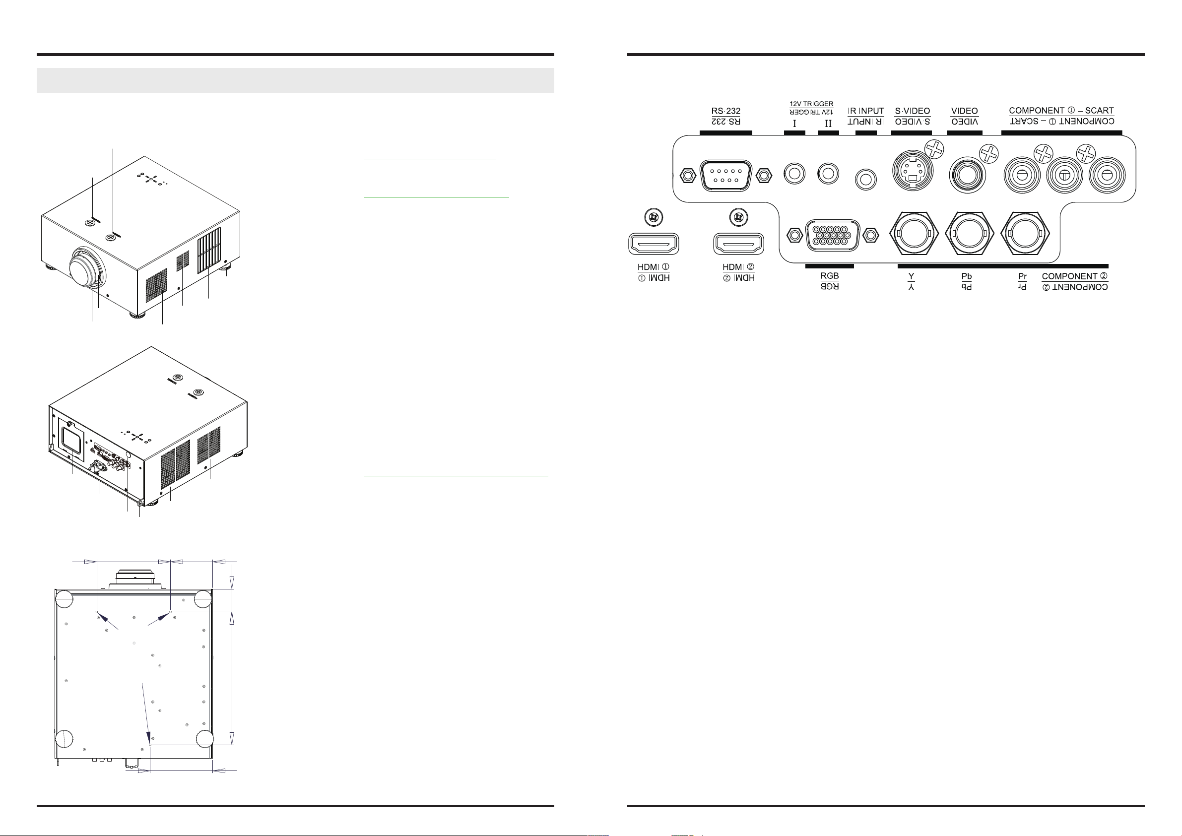
CONTROLS AND FUNCTIONS
D8300 at a Glance
Vertical Shift adjustment
Horizontal Shift
adjustment
Adjustable
feet*4
Air outlet
Zoom ring
Focus ring
Air inlet
Air outlet
y Vertical Shift adjustment
Refer to “Vertical Lens Shift” on page 18
y Horizontal Shift adjustment
Refer to “Horizontal Lens Shift” on page 18
y Focus ring
Rotate this to focus the projected image.
y Zoom ring
Rotate this to change the projected image size.
y Air outlet
Warm air exits the projector through this vent. Ensure
that it is not blocked
y Air inlet
Internal fans draw cool air into the projector through
this vent.
I/O Panel
y RS-232
9-pin D-sub connector for interfacing with a PC or home theater automation/control system.
y TRIGGER 1 , TRIGGER 2
(3.5-mm, mini phone jack) Offers 12 (+/- 1.5) V of output for 350mA monitor relay with short circuit protection.
Lamp Cover
Power inlet
Rear Infre-red window
(remote control)
Use screw x 3pcs
(M6, Lenght=10mm)
to x this machine on
the ceiling mount.
Kensington Lock
181.4
M6xL10
Air inlet
103.4
Air inlet
56.4
327
y Adjustable feet
Use these when the projector is installed in a tabletop configuration to level the image and/or adjust the
projection angle
y Lamp Cover
Refer to “To replace the projector lamp” on page 38.
y Power Inlet
For input power from wall outlet to projector.
y Rear Infre-red window
For receive the remote controller’s message.
y Kensington Lock
If you worry the security problem, attach the projector
to a permanent object with the Kensington slot and a
security cable.
y IR INPUT
Wired input from a Niles- or Xantech-compatible, infrared (IR) repeater system.
y S-VIDEO
A standard S-Video input for connecting a DVD player, satellite receiver or Super VHS (S-VHS) VCR.
y VIDEO
Standard composite video input for connecting a VCR, laser disc player or other composite video source. Also pro-vides
composite sync input for RGBS sources.
y COMPONENT 1/SCART (RCA connectors)
Standard or high-definition (480i/480p/576i/576p/720p/1080i/1080p) Component (YPbPr) input for connecting a
DVD/HD-DVD/BD player, HD set-top box or other SD/HD source. Also provides RGB input for RGBS sources.
y COMPONENT 2
Three BNCs for connecting component (YPbPr) video sources.
y RGB
Provides a standard, 15-pin VGA-style connection to either an RGB or component high-definition source, or to a per-
sonal computer.
The D8300 automatically detects the input signal resolution.
y HDMI1, HDMI2
For connect the device which have HDMI output connectors.
153.4
Ceiling mount dimension
10 11
Page 7
DLP Projector - User’s Manual
DLP Projector - User’s Manual
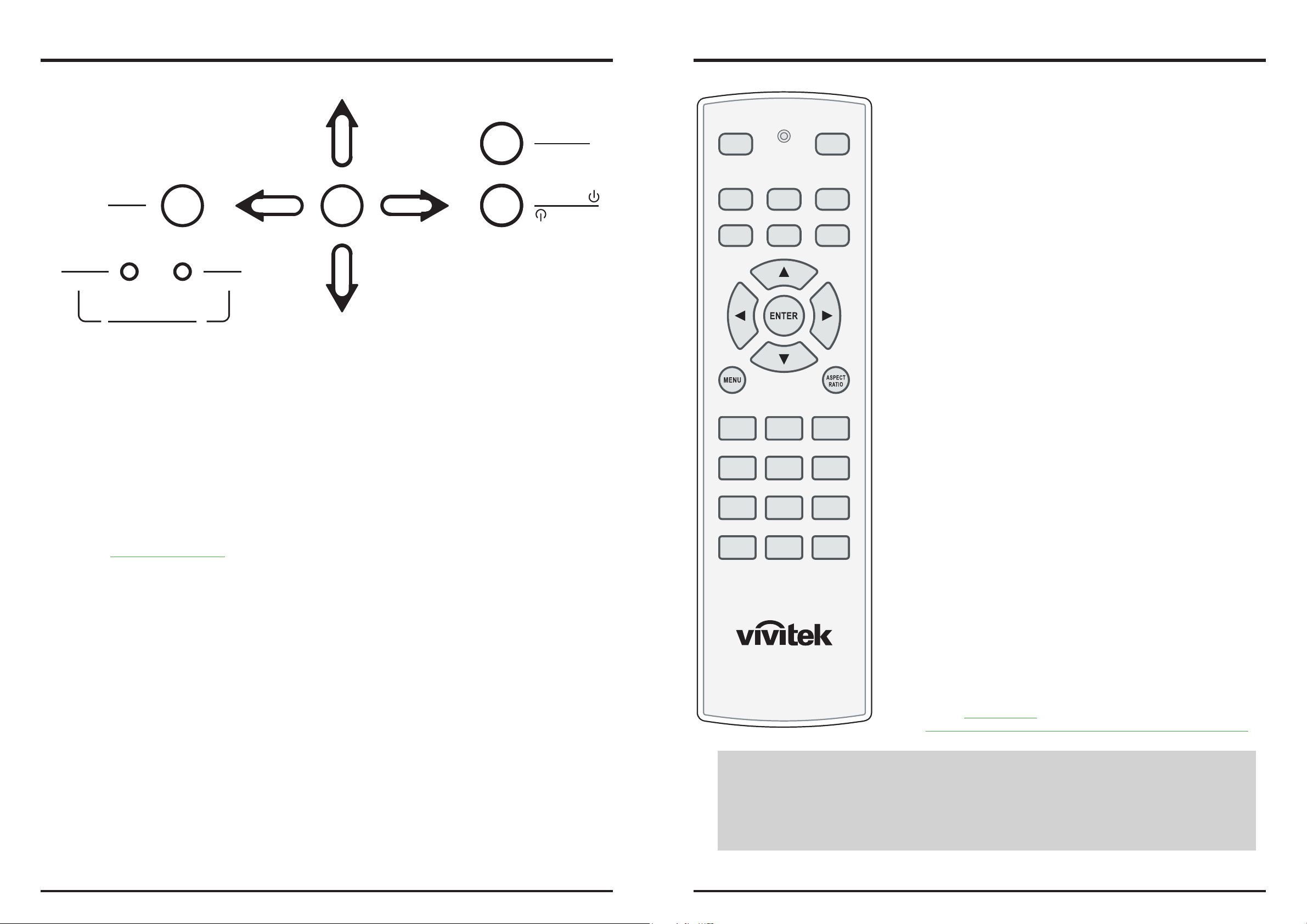
KEYPAD
E
L
C
E
MENU
POWER
POWER
LED STATUS
y MENU
Press this button to show or hide the OSD menu.
y SELECT, p, q, t, u
Use these buttons to select items or settings, adjust settings or switch display patterns.
y SOURCE
Press to select a video source. HDMI1, HDMI2, RGB, COMP1, COMP2, VIDEO or S-VIDEO.
y Power
Use the button to turn on/off the projector.
y LED STATUS
Refer to “LED Status” on page 40
MENU
ISSUE
LED STATUS
ISSUE
S
T
C
S
E
L
E
T
SOURCE
POWER
SOURCE
POWER
Remote control
ON
HDMI1
COMP1
CONT BRIGHT SHARP
GAMMA OS NR
PIP SWAP
HDMI2 RGB
COMP2 VIDEO
USER 2USER 1 TEMP
OFF
MP
● ON
Use this button to turn the projector on.
● OFF
Use this button to turn the projector off.
● HDMI1, HDMI2, RGB, COMP1, COMP2, VIDEO
Press to select a input source.
● ENTER, p, q, t, u
Use these buttons to select items or settings, adjust settings or switch display patterns. ENTER: Press to select a highlighted menu item or confirm a
changed setting.
● Aspect Ratio
Selection Button: Press this button repeatedly to select one of the follow ing aspect ratios: • 16 : 9: For viewing 16:9 DVDs or HDTV programs in their
native aspect ratio.
● MENU
Press this button to show or hide the OSD menu.
● USER1,USER2
Press to recall settings for the current input from one of two memory presets. By default, these buttons are assigned as follows: M1 = User Memory
1; M2 = User Memory 2. However, you can assign each button to any
memory preset you wish.
● Temp
This function is not availabel for this model.
● CONT
Adjust the Contrast value using t or u to highlight the differences between light and dark areas of the picture.
● BRIGHT
Adjust the Brightness value using t or u to lighten or darken the pic-ture.
● SHARP
Adjust the Sharpness value using t or u to sharpen or blur the borders
between colors and objects.
● GAMMA
adjustment to the light intensity (brightness) of an image in order to
match the source more closely.
● OS
Press to select an overscan mode
Note:When Native aspect is selected,Zoom is no available
● NR
Press to adjust noise reduction level.
● PIP
This function is not availabel for this model.
● SWAP
This function is not availabel for this model.
● MP
Refer to “Menu Position
Choose this function to decide the OSD menu’s position.” on page 33
Notes on Remote Control Operation
●In most situations, you can simply point the remote control at the screen which will reflect the IR signal
from the re-mote back toward the IR receiver on the projector. In some cases, however, ambient conditions
may prevent this. If so, point the remote control at the projector and try again.
● If the effective range of the remote control decreases, or it stops working, replace the batteries with new ones.
● The remote control may fail to operate if the infrared remote sensor is exposed to bright sunlight or fluores-
cent lighting.
12 13
Page 8
DLP Projector - User’s Manual
DLP Projector - User’s Manual
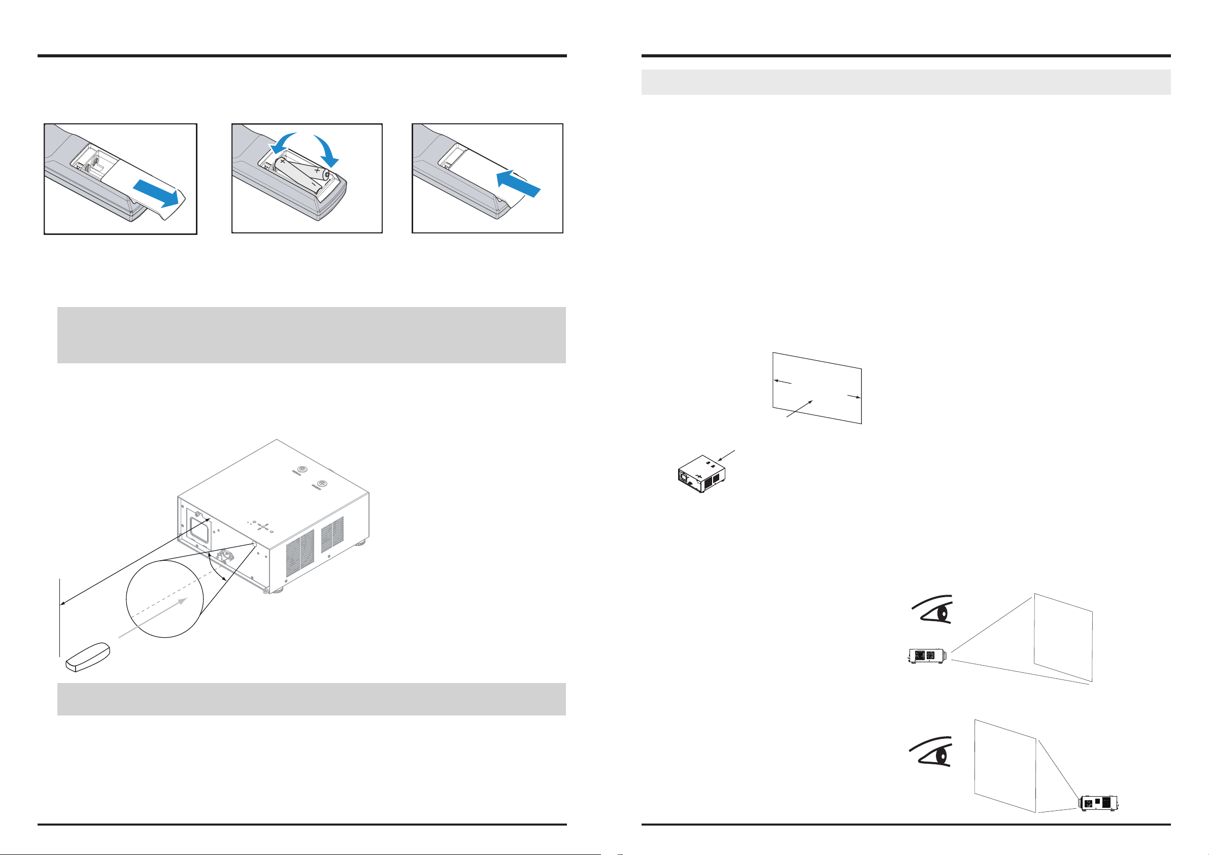
To install batteries in the remote control
STEP 1 STEP 2 STEP 3
1. Slide the battery compartment cover in the direction of the arrow to remove it.
2. Install two AA batteries with the correct polarity.
3. Replace the cover.
Notes on Batteries
y Make sure that the battery polarities are correct when installing the batteries.
y Do not mix an old battery with a new one or different types of batteries.
y If you will not use the remote control for a long time, remove the batteries to avoid damage from battery leakage.
Installation Considerations
Proper installation of your projector will ensure the quality of your display. Whether you are installing a projector temporarily or permanently, you should take the following into account to ensure your projector performs
optimally.
Ambient Light
In general, minimize or eliminate light sources directed at the screen. Contrast ratio in your images will be noticeably
reduced if light directly strikes the screen, such as when a shaft of light from a window or floodlight falls on the image.
Images may then appear washed out and less vibrant.
Requires separate room Installation cost is usually higher
Throw Distance
Throw distance is the distance measured from the front of the projector to the screen. This is an important calculation
in any projector installation as it determines whether or not you have enough room to install your projector with a desired screen size and if your image will be the right size for your screen. You can quickly estimate the throw distance by
taking the width of the screen and multiplying it by the lens throw ratio; see Figure 3-2. The result of this calculation tells
you roughly how far back the projector should be positioned from the screen in order to project a focused image large
enough to fill the screen.
Throw Distance (TD) = Screen Width (W) x Throw Ratio (TR)
Screen Width (W)
Range of effective remote control signal reception
40°
12m
IR Reception eective Angles: 40°
IR Reception eective distance: 12m
Note:
Avoid placing the remote control at places of high temperature or humidity as it could cause the remote control to
malfunction.
Throw Distance (TD)
Two models of the D8300 are available, one with 1.56-1.86:1 lens and the other with 1.85-2.40:1 lens With optional zoom
adaptors throw ratios of 1.24 – 3.0 can be achieved. The standard D8300 offers throw ratios between 1.85:1 and 2.40:1.
With the optional, short-throw lens, the D8300 offers throw ratios between 1.56:1 and 1.86:1.
Modes of installation
Frontal projection - desktop installaion
Advantages: easy to install can be easily moved or adjusted
easy to operate.
Disadvantage: occupies floor space and limits seating capac-
ity.
Rear projection - desktop installaion
Advantage: the projector is completely hidden from plain
view the projector can be easily operated this
setup usually offers better reduction of ambient
noise.
Projector
Projector
Disadvantage: requires an additional room for installation
relatively higher costs for installation.
14 15
Page 9

DLP Projector - User’s Manual
DLP Projector - User’s Manual
Frontal projection - ceiling mode
Advantage: does not occupy floor space does not draw
attention to it.Eliminates the possibility
that someone would accidentally move the
projector.
Disadvantage: stricter installation requirements and
conditions; care should be taken during
the installation to ensure the projector has
been securely mounted. operation of the
projector becomes inconvenient without the
remote control.
Rear projection - ceiling mode
Advantage: the projector is completely hidden from plain
view this setup usually offers better reduction of
ambient noise.
Disadvantage: requires an additional room for installation.
Stricter installation requirements and
conditions; care should be taken during the
installation to ensure the projector has been
securely mounted. operation of the projector
becomes inconvenient without the remote
control.
Projector
Do not tilt the projector more than 15 degrees.
The maximum tilt angle for the projector is 15 degrees.
When the projector is tilted more than 15 degrees, it will shorten the life of the projector lamp and may lead to other
unpredictable damages.
Projector
Can’t >15°
Can’t >15°
Other Considerations
y Install the projector in an environment below 35°C (95°F). The projector should be kept clear from sources of heat
and / or ventilation openings of air conditioner.
y The projector should be kept away from devices that emit electromagnetic energy, such as motor and transformer.
Common devices that emit electromagnetic energy include slideshow system, speakers, power amplifiers and
elevators.
y If you choose to install the projector on the ceiling, be sure to use the ceiling installation components
manufactured by manufacturer-certified vendors. For details, please contact your local dealer.
y Ensure that the intake vents do not recycle hot air from the exhaust vent.
Allow at least 50 cm clearance around the exhaust vent.
must > 50cm must > 50cm
must > 50cm
must > 30cm
must > 10cm
16 17
Page 10

DLP Projector - User’s Manual
DLP Projector - User’s Manual
Lens Shift
Vertical Lens Shift
The D8300 has a lens shift capability which allows the vertical movement of the image without moving the projector.
Lens shift is generally expressed as a percentage of the screen height. For ceiling mounted projectors, the lens can be
moved 120% (0.6V) downward, while the lens can be moved 120% (0.6V) up or down on a desktop mounted projector.
V
0.6V
0.6V
Range of vertical
lens shift adjustment
This illustration shows normal
vertical lens shift without the
use of special specification
lens or projector
Range of vertical
lens shift
adjustment
V
0.6V
Connecting the projector to other devices.
Proceed as follows to connect the D8300 to your video sources, external controller(s) - if present - and AC power.
When connecting your equipment: •Use the correct signal cables for each source. •Ensure that the cables are securely
connected. Tighten the thumbscrews on connectors that have them. Connecting Source Components to the D8300
Connect your video sources to the D8300 as shown and described in the sections that follow.
HDMI Connection
note:
This is a general example of lens shift. Lenses vary in their shift capabilities. No particular lens or projector is used in this
example.
Horizontal Lens Shift
The D8300 has a lens shift capability which allows the horizontal movement of the image without moving the projector.
The lens can be moved 30% (0.15H) to the right or left within the housing.
0.15H
H
0.15H
DVI Source(s)
(BD/HD-DVD/DVD Player, HD SetTop Box, Game Console etc.)
note:
This is a general example of lens shift. Lenses vary in their shift capabilities. No particular lens or projector is used in this
example.
18 19
Page 11

DLP Projector - User’s Manual
DLP Projector - User’s Manual
12V Trigger connection
If your home theatre system includes a projector screen, screen cover or other 12V Trigger equipment, please connect
such device/equipment to the projector’s 12V Trigger output as illustrated. After you have done so, Your screen will lower
automatically whenever you turn on your projector for your convenience.
Retractable screen or other
12V device
Sleeve = Ground
Tip = +12V
Projector Screen
S-VIDEO, VIDEO connection
If the image input device offers both S-Video and Video connection, it is recommended that you choose S-Video to obtain
better image quality.If both the S-Video and Video inputs are connected to the projector, the projector will prioritize SVideo signal input and image from the Video input will not be played.
DVD player, VCR, satellite receiver,
LD and so forth
IR Input connection
If infrared signals from the remote control cannot reach the projector due to excessive distance or obstructions such as
walls or cabinet doors, you can connect an external IR repeater system to the IR INPUT on the D8300 to extend the range
of the remote control.
IR sensor
IR repeater
Remote control
COMPONENT connection
Take the 3/5 cabled RGB component video connectors from the source equipment to the projector’s COMPONENT1 SCART
or COMPONENT2 jacks.
Y Pb Pr
DTV set-top-box or other component (YPbPr) input source
20 21
Page 12

DLP Projector - User’s Manual
DLP Projector - User’s Manual
RS-232 Controller Connection
Connect a PC or home theater control/automation system (if present) to the RS-232 port on the D8300. Use a standard,
9-pin serial cable, wired straight-through.
Desk Top or Notebook
Start using the projector - Adjustments
Connecting to AC Power
The D8300 ships with various types of AC power cords. Choose the one that is appropriate to your locale. Plug the female
end of the power cord into the AC receptacle on the rear of the projector (AC 100V ~ 240V); Then, connect the other end
to your AC power source.
Turning on the Power
Press the on button on Remote controller. The power LED indicator flashes green to indicate that it is warming up. When
the projector is ready for use, the LED indicator turns off, and the projector lights. button on the remote control to turn
on the D8300.
POWER
MENU
MENU
POWER
LED STATUS
ISSUE
LED STATUS
ISSUE
SOURCE
E
L
C
E
T
S
S
T
E
C
L
E
POWER
SOURCE
POWER
or
ON
HDMI1
COMP1
OFF
HDMI2 RGB
COMP2 VIDEO
Press Power
POWER LED
Flash Blue clolor
22 23
Page 13

DLP Projector - User’s Manual
DLP Projector - User’s Manual
Changing the OSD Language
The D8300 can display the menus in English, Simplify Chinese. Press MENU to display the OSD, Press to select
LANGUAGE item, then press to select a language that you wanted. Then press ENTER to confirm your selection.
Lens Adjustments
The D8300 gives you a great deal of control over the picture size, position and focus. Focus To focus the projected image,
grasp the lens by the front ring and rotate it.
Adjust foot
Rotate the 4 feet on projector for image position.
Note:
Ceiling Mode can’t adjust this function.
Vertical Shift adjustment
Horizontal Shift
adjustment
Vertical Lens Shift
To shift the projected image vertically, insert the provided hex
wrench into the hole at the top of the projector (directly above the
lens). Then, turn the wrench as shown to shift the lens in the desired
direction. Refer to “Vertical Lens Shift” on page 18
Adjusting the Picture Orientation
If the D8300 is installed behind the screen, you must change the picture orientation to match the installation method.
Refer to “Modes of installation” on page 15. To do this, press MENU on the remote control. Then select SYSTEM -> Rear
Projectior -> ON.
If the projector is ceiling-mounted, the D8300 will automatically inverts the image. If this automatic inversion is not de-sired,
please select Ceiling Mode from the OSD Menu -> SYSTEM -> Ceiling Mode -> ON.
Focus
Directly insert the
wrench into the hole
Remove the rubber pad
then insert the wrench
into the hole.
Zoom
Horizontal Lens Shift
To shift the projected image horizontally, insert the provided hex
wrench into the hole at the top of the projector. Then, turn the
wrench as shown to shift the lens in the desired direction. Refer to
“Horizontal Lens Shift” on page 18
When use hex wrench:
1. you can remove the rubber pad which cover the lens shift
hole. then insert the hex wrench into the hole and rotate the
wrench to adjust the picture’s position. Suggest you do this
action.
2. Or you can directly insert the hex wrench into the hole for
adjust the picture’s position. Of course the rebber pad will
break a hole.
Zoom
To make the picture smaller (zoom out) or larger (zoom in). Rotate
the zoom ring in the appropriate direction..
Focus
To make the picture clear or Fuzzy. Rotate the Focus ring appropriate
direction.
24 25
Page 14

DLP Projector - User’s Manual
DLP Projector - User’s Manual
Start using the projector - Operation
Selecting An Input Source
When you turn on the D8300, it switches to the last selected input and looks for a
valid signal. Use the input source buttons on the remote control to select an input
HDMI1
source directly.
COMP1
Selecting an Aspect Ratio
Press the aspect ratio button to select the appropriate aspect ratio for the type of
program material being
Using the OSD
1. Press the MENU button on the remote control or machine top cover’s keypad to display the OSD main menu.
2. Press or to select a sub-menu.
3. Press or to select a sub-menu item.
4. For each sub-menu item, the currently-selected value is highlighted. Press or to choose a setting for that item,
and press ENTER on the remote controller or SELECT on the keypad to adjust the value of that item.
5. If want return to the previous menu, please press MENU.
6. In the Main Menu, press MENU to turn off the OSD menu. The D8300 OSD menus are arranged
HDMI2 RGB
COMP2 VIDEO
Start using the projector - OSD Introduction
OSD Menu Tree
MAIN
ADVANCE
16:9
Letterbox
Aspect Ratio
Memory
Brightness 0~200
Contrast 0~200
Color Saturation Not availabel for this model
Color Tint Not availabel for this model
Sharpness 0~200
Noise Reduction 0~200
Overscan
Source Select
Resync ENTER
Color Space
Video Standard
Gamma
RGB Adjust
Fine Sync
Color Mode
4:3
4:3 Narrow
Native
Recall Memory
Save setting
Off
Crop
Zoom
HDMI1
HDMI2
RGB
COMP1
COMP2
VIDEO
Auto
REC709
REC601
RGB-PC
RGB-VIDEO
Auto
NTSC
PAL
SECAM
CRT
Film
Video
Bright
Grahpic
Red Offset
Green Offset
Blue Offset
Red Gain
Green Gain
Blue Gain
V Position
H Position
Phase
Tracking
Sync Level
Bright Mode
D65 Mode
D65 Color Mode
SYSTEM
Control
Language
SERVICE
Source Enable
Menu Position
Lamp Power
Blank Screen
Auto Power Off
Auto Power On
Rear Projection
Celling Mode
Triggle 1 Lamp
Triggle 2
Auto Source
H Keystone -35 ~ 0 ~ 35
V Keystone -20 ~ 0 ~20
English
簡體中文
Model Name
Serial Number
Software Version
Active Source
Pixel Clock
Signal Format
H/W Refresh Rate
Lamp Hours
Factory Reset
Blue Only
Altitude
HDMI1
HDMI2
RGB
COMP1
COMP2
VIDEO
S-Video
SCART
Economy
Standard
Logo
Black
Blue
White
ON
OFF
16:9
Letterbox
4:3
4:3 Narrow
RS232
ON
OFF
Yes
No
ON
OFF
26 27
Page 15

DLP Projector - User’s Manual
DLP Projector - User’s Manual
OSD Introduction - MAIN
y Brightness
Use to adjust the level of black in the image to increase or decrease image brightness.
y Contrast
Use to adjust the contrast of the projected image.
Note:
Brightness and Contrast controls are interactive. The screen change to one may require a subtle change to the other
in order to achieve the optimum setting.
y Sharpness
The adjustment of sharpness primarily changes the value of high frequency detail. Use to adjust it.
y Noise Reduction
Use to adjust the noise of the projected image. This function is suitable for the elimination of image noise
from interleaving SD input.Generally speaking, reducing image noise will lower the value of high frequency
detail and make the image appear more mellow.
y Overscan
Some consumers may use the image that input source is not 16:9, and some programs may not display the
edges of the image. Use this function to hide the image edge by choosing one of the following three options:
ZoomCropO
y ASPECT Ratio
This function allow user adjust the picture’s Aspect ratio. The following figure is an example for your reference.
Original input picture
16:9
Aspect Ratio
4:3
Aspect Ratio
16:9
Aspect Ratio
4:3 Narrow
Aspect Ratio
Letterbox
Aspect Ratio
Native
The part of the picture can not be projected
y Memory
Recall Memory: Select this item to recalll the your own setting.
Saving setting: You can adjust the OSD’s items by yourself then use this function to save your setting.
4:3
16:9
4:3
Narrow
Source image area
Native
(720p)
y Source Select
This function is same as the hotkey which on Remote controller. You can use Remote controller or this function
to select the correct input source. Refer to “Selecting An Input Source” on page 26.
y Resync
If the projected image becomes unstable or degraded. Use this function to adjust it. This causes a reacquisition of the present active source. It also changes any Fine Sync setting for this timing to the default
setting.
Edge Noise
Screen (16:9)
28 29
Page 16

DLP Projector - User’s Manual
DLP Projector - User’s Manual
OSD Introduction - ADVANCE
● COLOR SPACE
When the source signal for HDMI, RGB, and component connections. You can select different color space for
different color performance.
● The default setting, Auto, functions as follows:
HDMI: If the Auxiliary Video Information (AVI) infoframe contains color space and/or range data, the D8300 uses
that information. Otherwise, for RGB sources, the D8300 uses the RGB-Video color space. For component SDTV
and EDTV resolutions, REC601 is used. For other component video resolutions, REC709 is used.
RGB: If Hsync or Vsync signals are present, the D8300 uses the RGB-PC color space. Otherwise, REC601 is used
for SDTV and EDTV sources, and REC709 for all other sources.
Component: For SDTV and EDTV resolutions, the D8300 uses the REC601 color space. For all other resolutions
REC709 is used.
● In most cases, the Auto setting determines the correct color space to use. If it does not, you can force the D8300
to use a specific color space. Choose one of the following:
REC709 sets the color space matrix to that defined in ITU-R BT.709.
REC601 sets the color space matrix to that defined in ITU-R BT.601.
RGB-PC uses RGB color space and sets black at 0,0,0 RGB and white at 255,255,255 RGB, assuming an 8-bit im-
age.
RGB-Video uses RGB color space and sets black at 16,16,16 RGB and white at 235,235,235, assuming an 8-bit
image, to correspond to the luminance values defined in digital component standards.
Different countries may use different video signal formats. Please choose the video standard in your area.
● Auto
The color systems are automatically identified and the format is set accordingly.
● NTSC (National Television Systems Committee)
This is the standard format used mainly in the United States and Japan.
● PAL (Phase Alternation By Line)
This is the standard used in Europe, Australia and many other parts of the world, typically with a 50Hz frame
rate.
● SECAM (Sequential Color With Memory)
This is a standard format used mainly in France and Russia. Gamma: Select Gamma from the ADVANCED menu
to choose a DLP de-gamma curve. Used correctly, the Gamma control can improve contrast while maintaining
good details for blacks and whites. If excess ambient light washes out the image and it becomes difficult or
impossible to see details in dark areas, low-er the gamma setting to compensate. This improves contrast while
maintaining good details for blacks. Conversely, if the image is washed out and unnatural, with excessive detail
in black areas, increase the setting.
Note:
Generally speaking, the projector will be able to automatically detect the video standard used in your area. However, there are
circumstance where the projector will fail to interpret the video standard used and the user will have to manually configure
the video format. If you are unsure of the video standard used in your area, please contact a qualified personnel and inquire
about the video standard used in your area.
● Gamma
Different Gamma settings will affect viewers’ perception of the image. Generally speaking, for images that are darker,
it is recommended that Gamma be set higher to yield better image quality in darker regions by sacrificing details in
brighter areas. In contrast, when projecting brighter images, you can set the Gamma lower to give up details in the
darker areas to make the brighter areas (i.e. clouds) more visible.
● CRT sets the gamma to 2.5.
● Film sets the gamma to 2.2.
● Video is similar to Film gamma but differs in dark areas of the image to correspond to the function that video
cameras use to create images.
● Bright sets the gamma to 2.0.
● Graphics should only be used for computer presentations that require increased brightness at the cost of
grayscale accuracy.
● RGB Adjust
For remove any trace of color from the white areas of the projected image.
● Gain
Use the Gain controls to correct color imbalances in the bright areas of the image. A good way to do this is to
use a test pattern consisting mostly of solid white areas, such as an 80 IRE “window” pattern. If the white areas
contain traces of red, green or blue, decrease the Gain for that color.
● Offset
Use the Offset controls in the RGB Adjust sub-menu to correct color imbalances in the dark areas of the image.
A good way to do this is to use a test pattern consisting mostly of dark gray areas, such as a 30 IRE “window”
pattern. If the gray areas contain traces of red, green or blue, decrease the Offset for that color.
The Gain controls increase or decrease the full-scale input range; the Offset controls shift the entire range,
resulting in a change in brightness.
Generally, higher Gain settings reduce the image contrast; higher Offset settings reduce the image brightness.
● Video Standard
30 31
● Fine Sync
Page 17

DLP Projector - User’s Manual
DLP Projector - User’s Manual
To fine-tune the position and other image attributes.
y V Position:
Select this function to adjust the vertical position of the image within the designated image area, up to 25%
up or down of the image height.
y H Position
Select this function to adjust the horizontal position of the image within the designated image area, up to 25%
right or left of the image width.
y Phase (for RGB or Component sources)
This control adjusts the phase of the pixel sampling clock relative to the incoming signal. Adjust the phase
when an RGB or Component image still shows shimmer or “noise” after Tracking has been optimized.
Note:
Adjust the Phase after adjusting Tracking (see below). If some shimmer from a video or HDTV source persists, use the
Noise Reduction controls to remove high-frequency noise from the signal.
y Tracking (for RGB or Component sources)
Tracking determines the frequency of the pixel sampling clock, indicated by the number of incoming pixels
per line, so that all pixels generated by a particular source are sampled.
Steady flickering or several soft vertical stripes or bands across the entire image indicates poor pixel tracking.
Proper pixel tracking helps ensure that the image quality is consistent across the screen, that aspect ratio is
maintained and that pixel phase can be optimized.
OSD Introduction - SYSTEM
y Sync Level (for Component sources only)
Select Sync Level to adjust the voltage level of the D8300 Sync signal detection circuitry.
Sync Level adjustment is occasionally necessary when a DVD player or HDTV source signal drops “below black”
(for example, during scenes with explosions or when subtitles are present) and causes the projector to temporarily lose sync. If the Sync Level from the source is persistently too low, the projector won’t sync with the
source at all.
The range is from 50 to 256 millivolts (mV) inclusive. The default setting is 240 mV and should rarely require
adjustment.
y Color Mode
y Bright Mode
Choose this item to get the Bright color.
y D65 Mode
Color performance between Bright and D65 Color mode.
y D65 Color Mode
Choose this mode to get the beautiful(High saturation) color.
y Source Enable
To enable or disable selection of a picture’s input source.
When the source “ HDMI1” set as off. The input source “HDMI1” will became Gray. Can’t select.
y Menu Position
Choose this function to decide the OSD menu’s position.
y Lamp Power
y Economy
Power-saving mode. Select this lamp output level will reduce lamp’s brightness, but it can prolongs the life of
the lamp. This setting is per source, not global, so it can be saved like other user settings.
y Standard
Choose this item to run the lamp as bright as possible (400W).
y Blank Screen
Use this function to specify the content or color to be displayed on the blank screen when no input signal is available.
You can choose from Logo, Blue, Black, White.The default value is Logo.
y Auto Power Off
The default value is OFF. If you set it to ON, the projector will automatically shut down after 20 minutes without input
signal.
32 33
Page 18

DLP Projector - User’s Manual
DLP Projector - User’s Manual
y Auto Power ON
The default value is Off. If you set it to ON, the projector will automatically start up when it is connected to AC power. If
you plug the projector’s power cord into an AC socket with a switch, you can use this function to start up the projector
using the socket’s switch instead of the remote. If you do not need this function, please set it to Off.
y Rear Projection
This control reverses all images and menus, and is necessary when the projector is used in rear-projection applications.
The default is Off. Refer to “Modes of installation” on page 15.
y Celling Mode
This control flips the image so the projector can be used in ceiling mounted installations. The default setting, Auto,
automatically determines the orientation using an internal sensor. Refer to “Modes of installation” on page 15.
OSD Introduction - CONTROL
y Auto Source
Off: default setting. By enabling this function, the projector will automatically determine the source of input every time
it is turned on so that the user will not have to make the selection on the OSD Menu.
Setting the function off will require the user to specify source of image input on the OSD Menu in order for the
projector to display the intended image.
y H Keystone , V Keyston
Use this function to correct keystoning caused by projection angle.
V Keystone
20
H Keystone
-35
H Keystone
V Keystone
0
V Keystone
-20
H Keystone
35
y Triggle 1, Triggle 2
The projector comes with two sets of Trigger output. You can configure two different devices connected to the projector via the trigger ports to be automatically turned on when the projector is on. There will be a 2-3 second delay prior
to activation to prevent operation of this function when the user is choosing the desired aspect ratio.
y Lamp Outputs 12V of power on Trigger1 or 2 when the lamp is on.
y 16:9 Outputs 12V of power on Trigger1 or 2 when chooses the 16:9 aspect ratio.
y Letterbox Outputs 12V of power on Trigger1 or 2 when chooses the Letterbox aspect ratio.
y 4:3 Outputs 12V of power on Trigger1 or 2 when chooses the 4:3 aspect ratio.
y 4:3 Narrow Outputs 12V of power on Trigger1 or 2 when chooses the 4:3 narrow aspect ratio.
y RS232 Outputs 12V of power on Trigger 1 or 2 when the projector receive the message from RS232.
OSD Introduction - LANGUAGE
Choose the OSD display language that you familiar. English or Simple-Chinese.
34 35
Page 19

DLP Projector - User’s Manual
DLP Projector - User’s Manual
OSD Introduction - SERVICE
y Blue Only
Enabling this option will make the projector display only blue color to facilitate the process of image inspection for the service personnel. For detailed instructions on how to use this function, consult a qualified service
personnel.
y Altitude
Use this function to control the projector’s cooling fan. You can set it to Off or On. The default setting is Off.
Under normal circumstances, the projector will operate normally with this function set to Off. By default, the
projector will detect the temperature of the surrounding environment to regulate the speed of the cooling fan.
When the ambient temperature rises, fan speed will increase (generates louder noise) to make sure the heat
inside the projector gets discharged and keep the projector working normally.
However, if you were to operate the projector in environment of excessive heat or in areas of high altitude, the
projector may automatically shut down. When this happens, you can enable this function by setting it to On to
force the cooling fan to work at a higher speed to regulate the temperature inside the projector.
High altitude region refers to area with elevation over 5000 feet.
The functions covered in this unit relate to the display of some basic information about the projector.
Memory of the custom timing files will be erased in the Factory Reset operation.
y Model: the designated model number of the projector.
y Serial Number: the designated serial number of the projector.
y Software Version: the version of software installed on the projector.
y Active Source: displays the current PIP sources.
y Pixel Clock: displays the pixel clock of the current input signal.
y Signal Format: displays the format of the current input signal.
y H/V Refresh Rate: displays the horizontal and vertical refresh rates for the current image.
y Lamp Hours
Display the lamp usage time. When you change the new lamp. The lamp hours will re-calculate the time.
y Factory Reset
Use this function to restore the configurations in the OSD Menu back to factory default. Note that this function will not
apply to items including no signal, network, Projector control, startup Logo, language, High Altitute mode and lamp
hours.
When Factory Reset is executed, all source memories created by the projector (i.e. timings files) will be erased.
36 37
Page 20

DLP Projector - User’s Manual
DLP Projector - User’s Manual
Change Lamp
The lifecycle of ordinary projection lamp typically lasts for 1500 hours (Normal mode), 1000 hours(Economy mode)
before requiring replacement (different lamp configurations will affect lamp life). From the OSD Menu, you can go to
" “OSD Introduction - SERVICE” on page 36 ". to check how long a lamp has been used. You should also replace the
lamp when the projected image gets noticeably darker.
your projector.
To replace the projector lamp
1. Turn off the projector and unplug the power cord. Let the projector cool for approximately 60 minutes before removing the lamp module for replacement.
When you turn off the projector, the lamp inside the projector will still be very hot (approximately 200 ~ 300°C). If you attempt to replace the lamp without allowing the projector to cool, you could risk scalding yourself. This is why you should
wait for no less than 60 minutes for the lamp to cool down in order to perform the replacement safely.
2. Loosen the lamp cover.
Contact your local dealer to purchase new certified lamps for
6. Replace the lamp cover and firmly secure the two
screws on the lamp cover.
3. Use a screw driver to loosen the screws as shwon in
the illustration.
4. Grasp the metal rod on the lamp cover and pull the
lamp out.
5. Insert the new lamp in the direction shown in the
illustration into the lamp assembly; tighten the two
screws using a screw diver and make sure the lamp is
firmly secured to prevent the lamp from shaking or
poor contact.
38 39
Page 21

DLP Projector - User’s Manual
DLP Projector - User’s Manual
LED Status
POWER
POWER
LED STATUS
POWER
● Turns blue
Indicate projector is turned on, and can function properly.
● Flash blue
Indicate the projector is in the warming or cooling time. In this situation, the function of keypad is not available.
● Off
This indicates that the projector has either been turned on and is working normally or the projector is not connected
to power.
ISSUE
● Flashes once in red
The projector lamp is faulty; check to see if the lamp is damaged or if it hasn't been properly installed.
● Flashes twice in red
The lamp cover is not properly replaced.
● Flashes three times in red
The cooling fan inside the projector is not working; seek assistance from a qualified service personnel.
● Flashes four times in red
The projector temperature is too high; try cleaning the ventilator slots or unplugging the power cord to resolve
the issue.
● Flashes five times in red
The projector filter might not have been inserted properly; check the ventilation slot and make sure the filter has been
properly replaced and inserted.
● Turn Red
The projector’s system has problem. Please contact the service center.
Blue
(POWER)
Standby
Cooling / Warm up
Power on / Normal
Lamp fail
Lamp door open
Fan fail
Over Temperature
Filter fail
System Error
ISSUE
ISSUE
LED STATUS
Red
(ISSUE)
repeat
repeat
repeat
repeat
repeat
SPECIFICATIONS
Optical
● Digital Light Processor 1 x 0.95” Texas Instruments DMD™,resolution 1920 x 1080 pixels
● Colour wheel 6-segment: (RGBYCW) (3x)
● Contrast Ratio 3000: 1 (±10%)
● Colour temperature Native: 7000°K (±1500°K)
● Pixel fill factor 87%
● Lamp power 400W
● Lamp life (typical) 1500 hours
● Brightness 7000 ANSI lumens (±10%)
● Uniformity 85%
Electrical
● Inputs HDMI x 2, RGB, Component x 2, Video, S-Video
● Pixel clock (digital) up to 165MHz
● Bandwidth (analog) 200MHz
● Control inputs 1 x RS232 serial: 38400 baud, 8 bits, 1 stop bit, no parity 1 x remote control
● Mains voltage 100-240 VAC ±10%, 47-63Hz (single phase)
● Power consumption
110V 347W in Running mode, 1.9W in Standby
240V 331W in Running mode, 2.5W in Standby
● International Regulations Meets FCC Class B requirements
Meets EMC Directives (EN 55022, EN 55024)
Meets Low Voltage Directive (EN60950)
● Indicators Power, Standby, Issue (Fault)
Physical
● Temperature
Operating 10 to 35°C
Storage -20 to 60°C
● Thermal Dissipation 1500 BTU/hr
● Humidity
Operating 20% to 90% non condensing
Storage 10% to 90%
● Altitude
Operating up to 10,000 feet
Storage up to 40,000 feet
● Weight 15 kg (33.07 lbs)
● Noise level < 45 dB
40 41
Page 22

DLP Projector - User’s Manual
SERIAL INTERFACE SPECIFICATIONS
Transfer Specifications
DLP Projector - User’s Manual
item Specifications
Transmission Speed 38400 bps
Data Length 8 bit
Parity None
Stop Bit 1
Flow Control None
RS-232 Commands
There are 2 types of commands:
● Key commands
● Operation commands
All commands start with 2 letters as shown in the following:
● “ky” for key commands.
● “op” for operations commands.
● Key Commands The following example is the syntax for key commands: ky <keyname> [CR]
IR Codes and Key names
Key Code RS232 Key name Function Key Wording Description
1 0x01 pow.on Power On ON Turn power on
2 0x09 pow.off Power Off OFF Turn power off
9 0x1A cur.up Keypad Down Arrow.
10 0x1D cur.left Keypad Left Arrow.
11 0x17 enter Enter ENER Key pad enter.
12 0x1F cur.right Keypad Right Arrow.
13 0x18 cur.down Keypad Up Arrow.
14 0x15 menu Bring Up or Cancel Menu Display. MENU Bring up or cancel menu display
p
t
u
q
Key pad up arrow.
Key pad left arrow.
Keypad right arrow.
Key pad down arrow.
Operation Command Values
source.sel = ? 0 = HDMI 1
1 = HDMI 2
2 = RGB
3 = YPrPb 1
4 = YPrPb 2
5 = S-video
6 = Video
aspect = ? 0 = 16:9
1 = Letterbox
2 = 4:3
3 = 4:3 Narrow
4 = Native
bright = ? + - 0 - 200
contrast = ? + - 0 - 200
sharp = ? + - 0 - 200
nr = ? + - 0 - 200
overscan = ? 0 = Off
1 = Crop
2 = Zoom
resync (execute)
color.space = ? 0 = Auto
1 = YPbPr
2 = YCbCr
3 = RGB-PC
4 = RGB-Video
gamma = ? 0 = CRT
1 = Film
2 = Video
3 = Bright
4 = Graphics
red.off = ? + - 0-200
green.off = ? + - 0-200
blue.off = ? + - 0-200
red.gain = ? + - 0-200
green.gain = ? + - 0-200
Operations Commands
The following example is the syntax for operations commands:
op <operation> <command> [CR]
No. Function Command Action on unit
1 Set =<value> Makes the unit take that value.
2 Get ? Asks what the current value is.
3 Increment + Adds 1 to the current value.
4 Decrement - Subtracts 1 from the current value.
5 Execute (none) Performs an action.
42 43
Page 23

DLP Projector - User’s Manual
blue.gain = ? + - 0-200
vert.pos = ? + - 0-200
horiz.pos = ? + - 0-200
menu.pos = ? 0 = Top left
1 = Top right
2 = Bottom left
3 = Bottom right
4 = Center
auto.pow.off = ? 0 = Off
1 = On
auto.pow.on = ? 0 = Off
1 = On
rear.proj = ? 0 = Off
1 = On
ceil.mode = ? 0 = Off
1 = On
model.name ? <string>
ser.number ? <string>
soft.version ? <string>
act.source ? 0 = HDMI 1
1 = HDMI 2
2 = RGB
3 = YPrPb 1
4 = YPrPb 2
5 = S-video
6 = Video
h.refresh ? <number> kHz
v.refresh ? <number> Hz
pixel.clock ? <number> MHz
signal ? <string>
lamp.hours ? <number>
Lamp.reset (execute)
fact.reset (execute)
altitude = ? 0 = off
1 = on
v.keystone = ?
h.keystone = ?
memory = 0 - recall user memory 1
?
<number>
<number>
1 - recall user memory 2
DLP Projector - User’s Manual
44 45
Page 24

DLP Projector - User’s Manual
DLP Projector - User’s Manual
Dimensions
388.2
162.5
182.3
416.4
Supported Timings
Signal
Type
PC
Apple Mac 640x480 66.59 X X
SDTV
EDTV
Resolution
640x480 59.94 X X
640x480 74.99 X X
640x480 85 X X
800x600 60.32 X X
800x600 75 X X
800x600 85.06 X X
848x480 47.95 X X
848x480 59.94 X X
1024x768 60 X X
1280x1024 60.02 X X
1280x1024 75.02 X X
1280x1024 85.02 X X
1600x1200 60 X X
1680x1050 59.954 X X
1920x1080 47.95 X X
RGBs 50 X
1440x480i 60 X
1440x576i 50 X
480i 59.94 X
576i 50 X
480p 59.94 X X X X
576p 50 X X X X
1035i 60 X X X X
1080i 50 X X X X
1080i (Aus) 50 X X X X
1080i 59.94 X X X X
1080i 60 X X X X
720p 50 X X X X
720p 59.94 X X X X
Frame
rate
DVI Video SCART S-Video Y-Pb-Pr HD15-YUV
HD15RGB
HDTV
NTSC
PAL
SECAM SECAM (M) 50 X X
46 47
720p 60 X X X X
1080p 23.98 X X X X
1080p 24 X X X X
1080p 25 X X X X
1080p 29.97 X X X X
1080p 30 X X X X
1080p 50 X X X X
1080p 59.94 X X X X
1080p 60 X X X X
NTSC
(M 4.43)
PAL
(B,G,H,I)
PAL (N) 50 X X
PAL (M) 59.94 X X
59.94 X X
50 X X
Page 25

DLP Projector - User’s Manual
DLP Projector - User’s Manual
Projection Distance and Screen Size
Screen Size: This is the size of the screen not the size of the projection
In case of display 16:9 picture on the whole 16:9 Screen 16:9 Screen TR: 1.85~2.4TR = PD / SW
Unit: Inch
Screen Size Projection Distance
Diagonal Width Height Min. Max.
60 52.29 29.41 96.74 125.50
70 61.01 34.32 112.87 146.42
72 62.75 35.3 116.09 150.60
80 69.72 39.22 128.99 167.34
82 71.47 40.20 132.21 171.51
84 73.21 41.18 135.44 175.71
90 78.44 44.12 145.11 188.26
92 80.18 45.10 148.34 192.44
100 80.18 45.10 148.34 192.44
106 92.38 51.97 170.91 221.72
110 95.87 53.93 177.36 230.09
120 104.59 58.83 193.49 251.01
123 107.20 60.30 198.32 257.28
133 115.92 65.20 214.45 278.20
135 117.66 66.18 217.67 282.38
150 130.73 73.54 241.86 313.76
170 148.16 83.34 274.10 355.59
200 174.31 98.05 322.48 418.35
250 217.89 122.56 403.09 522.93
300 261.47 147.07 483.71 627.52
Diagonal Width Height Min. Max.
60 1219 914 2256 2926
70 1422 1067 2631 3414
72 1463 1097 2707 3511
80 1626 1219 3007 3901
82 1666 1250 3083 3999
84 1707 1280 3158 4097
90 1829 1372 3383 4389
92 1869 1402 3458 4487
100 2032 1524 3759 4877
106 2154 1615 3985 5169
110 2235 1676 4135 5364
120 2438 1829 4511 5852
123 2499 1875 4624 5998
133 2703 2027 5000 6486
135 2743 2057 5075 6584
150 3048 2286 5639 7315
170 3454 2591 6391 8291
200 4064 3048 7518 9754
250 5080 3810 9398 12192
300 5096 4572 11278 14630
In case of display 16:9 picture on the whole 4:3 Screen 4:3 Screen TR: 1.85~2.4TR = PD / SW Unit: Inch
Screen Size Projection Distance
Diagonal Width Height Min. Max.
60 48.00 36.00 88.80 115.20
70 56.00 42.00 103.60 134.40
72 57.60 43.20 106.56 138.24
80 64.00 48.00 118.40 153.60
82 65.60 49.20 121.36 157.44
84 67.20 50.40 124.32 161.28
90 72.00 54.00 133.20 172.80
92 73.60 55.20 136.16 176.64
100 80.00 60.00 148.00 192.00
106 84.80 63.60 156.88 203.52
110 88.00 66.00 162.80 211.20
120 96.00 72.00 177.60 230.40
123 98.40 73.80 182.04 236.16
133 106.40 79.80 196.84 255.36
135 108.00 81.00 199.80 259.20
150 120.00 90.00 222.00 288.00
170 136.00 102.00 251.60 326.40
200 160.00 120.00 296.00 384.00
250 200.00 150.00 370.00 480.00
300 240.00 180.00 444.00 576.00
In case of display 16:9 picture on the whole 4:3 Screen 4:3 Screen TR: 1.85~2.4TR = PD / SW Unit: mm
Screen Size Projection Distance
48 49
Page 26

http://www.vivitekcorp.com
 Loading...