

Vivitek D5500 series Service Manual

DDM
Disclaimer
Disclaimer
This user manual is provided as a free service by FixYourDLP.com. FixYourDLP is in no way responsible
for the content of this manual, nor do we guarantee its accuracy. FixYourDLP does not make any claim
of copyright and all copyrights remain the property of their respective owners.
About FixYourDLP.com
FixYourDLP.com (http://www.xyourdlp.com) is the World’s #1 resource for media product news,
reviews, do-it-yourself guides, and manuals.
Informational Blog: http://www.xyourdlp.com
Video Guides: http://www.xyourdlp.com/guides
User Forums: http://www.xyourdlp.com/forum
FixYourDLP’s Fight Against Counterfeit Lamps:
http://www.xyourdlp.com/counterfeits
Sponsors:
Sponsors:
RecycleYourLamp.org – Free lamp recycling services for used lamps:
http://www.recycleyourlamp.org
Lamp Research - The trusted 3rd party lamp research company:
http://www.lampresearch.com
Discount-Merchant.com – The worlds largest lamp distributor:
http://www.discount-merchant.com
Sponsored by
M
Delta Elec. Inc. Vivitek rev.00
THE TRUSTED SOURCE FOR PROJECTOR LAMPS AND ACCESSORIES
PROJECTOR
D5500 Serial
SERVICE MANUAL (Rev.00)
Company Confidential VIVITEK_______________________ Delta____________
1
2008/07/28
Delta Elec. Inc. Vivitek rev.00
THE TRUSTED SOURCE FOR PROJECTOR LAMPS AND ACCESSORIES
DLP DIGITAL PROJECTOR Rev.00
Model Name: D5500 Serial
Revision Description Date
00 Preliminary 07/28/2008
Company Confidential VIVITEK_______________________ Delta____________
2
2008/07/28
Delta Elec. Inc. Vivitek rev.00
THE TRUSTED SOURCE FOR PROJECTOR LAMPS AND ACCESSORIES
CONTENTS
1. COMPLIANCE OF SAFE REP AIR .........................................................………………………………..…….……5
1-1. Caution during disassembling and assembling ..................……………………………………..…….……5
1-2. Lamp .......... ..............................................................……………………………………………….……….….5
1-3. Lens ............................................................…………………………………………………….…………….….5
2. SPECIFICA TIONS .........................................................…………………………………………………………..…6
2-1. Optical Specifications …………………………………………………………………… …… …………..……… 6
2-2. Electrical Specifications ………………………………………… …………………………………..………… …7
2-3. Mechanical Specifications …………………………………………………………………………………...….8
2-4.Environmental considerations…………………………………………………………….………….……...….8
2-5. Views of projector parts……………………………………………………………………………………………9
2-6. Top features…………………………………………………………………………………………………….…..11
2-7. Terminal panel features.………………………………………………………………………………….………14
2-8. Remote control parts……… …………………………………………………………………………………..…16
2-9. Inserting the remote control batteries……………………………………………………………………..….18
2-10. Block Diagram ……………………………………………………………..……………………………..…..…19
2-11. Explanation of the block diagrams …………………………………………...………..……………………20
2-12. Wire Location ……………………………………………………………..….……………………………...…..22
3. TROUBLE SHOOTING ……………………………………………………………… ……………….……………..…23
3-1. Operation check ………………………………………………………..…………………………………………23
3-2. Main Board check ……………………………………………………………………………………………..….24
3-3. LED State Indications ………………………………………………………….………………………………...26
4. DISASSEMBLY AND ASSEMBLY ………………………………………….…………………………………..…….27
5. ADJUSTMENT………………………………………………………………………… ……………………………..….57
5-1. Step of Into Service mode………………………………………….…………………………..………………..57
5-2. Calibrate VGA (1024 x 768 @ 60Hz)………….....................................................................……………....58
5-3. Calibrate YUV…………………………………………………………………………………….…………..…….59
5-4. Calibrate Video……………………………………………………………………………………………………..60
5-5. Color Wheel Index Adjustment……………………………………………………………….………….……..63
5-6. Focus Adjustment…………………………………………………………………………………………………65
6. SECURITY NOTICE………………………………………………………………………………………………..…...72
6-1. Preventing the Unauthorized Use of the Projector……………………… ……..………………………..….72
6-2. Unlocking the Projector…………………………………………………………………………………..……...74
6-3. Security function notice……………………………………………………………………… ………………….74
7. Circuit Protections ………………………………………………………………………………………………….....75
Company Confidential VIVITEK_______________________ Delta____________
3
2008/07/28
Delta Elec. Inc. Vivitek rev.00
THE TRUSTED SOURCE FOR PROJECTOR LAMPS AND ACCESSORIES
7-1. Fuse ………………………………………………………………………………………………………………..75
7-2 Thermostat ………………………………………………………………………………………………………...76
7-3 Bimetal ……………………………………………… ……………………………………………………………..77
7-4 Lamp Interlock Switch …………………………………………………………………………………………..78
8. Maintenance …………………………………………………………………………………………………………...79
8-1 Cleaning the projector ………………………………………………………………… ………………………..79
8-2 Replacing Consumable Parts ………………………………………………………………………………….83
9. Factory Preset Display Modes ……………………………………………………………… ……………………..87
10. Spare part list ………….…………….…..……………………………………………………….……………….…91
11. Required adjustments when the parts replaced ………………………………..……….….…………………96
Company Confidential VIVITEK_______________________ Delta____________
4
2008/07/28

Delta Elec. Inc. Vivitek rev.00
THE TRUSTED SOURCE FOR PROJECTOR LAMPS AND ACCESSORIES
1. COMPLIANCE OF SAFE REPAIR
Be sure to read this Service Manual before providing services. In the projector, full consideration is taken
to ensure the safety for a fire, electric shock, injury, harmful radiation, and substance. Therefore, observe the notice described
in this Service Manual so that the safety is kept when providing services. Moreover, be sure to observe the notice described
in the Instruction Manual. Pay attention to the following during service inspection.
1-1. Cautions during disassembling and assembling
1.This equipment contains parts under high voltage. When making repairs, etc. Be sure to pull out the power
plug beforehand to insure safety.
2. Parts may be very hot immediately after use. Make sure the equipment has cooled off sufficiently before
carrying out repairs.
3. Make sure that parts and screws and wiring, etc. are returned to their original positions. Tube, tape and
other insulation materials have been used for safety reasons. The internal wiring has been designed to
avoid direct contact with hot parts or parts under high voltage when using clamps or other tools.
4. The parts used in this device have special safety features such as flame-resistance and anti-voltage
properties. When replacing parts, always use parts supplied from the factory.
5. After finishing operations make sure that all parts and wires have been returned to their original position
and that there has been no deterioration of the area around the location that was worked on.
6. Be sure to use an earth band (wrist band) during repair and inspection.
1-2. Lamp
During current conduction, the lamp is in the high-temperature state. In this case, pay careful attention
because a high voltage is used. When replacing a lamp, replace it after confirming that the lamp has gotten
cold sufficiently.
1-3. Lens
Do not look through a lens during projection. This damages your eyes.
Company Confidential VIVITEK_______________________ Delta____________
5
2008/07/28
Delta Elec. Inc. Vivitek rev.00
THE TRUSTED SOURCE FOR PROJECTOR LAMPS AND ACCESSORIES
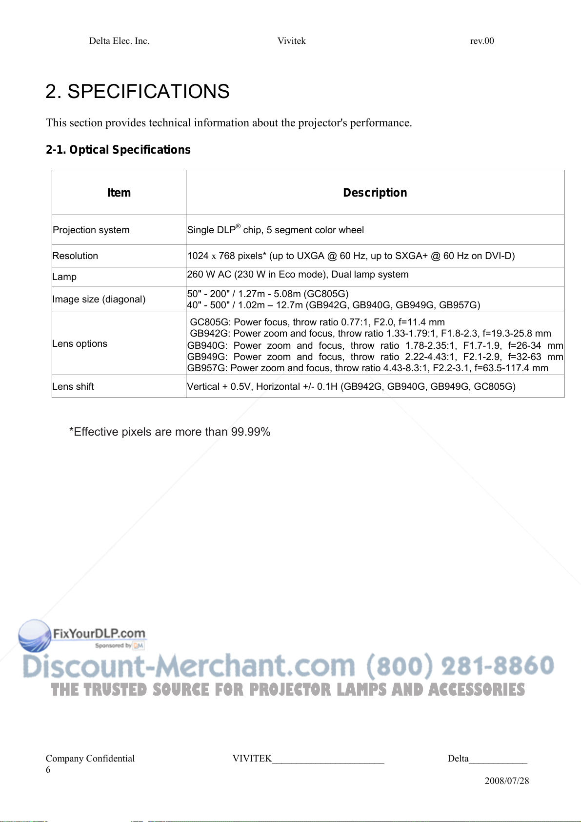
2. SPECIFICATIONS
This section provides technical information about the projector's performance.
2-1. Optical Specifications
Item Description
Projection system Single DLP® chip, 5 segment color wheel
Resolution 1024 x 768 pixels* (up to UXGA @ 60 Hz, up to SXGA+ @ 60 Hz on DVI-D)
Lamp
Image size (diagonal)
Lens options
Lens shift Vertical + 0.5V, Horizontal +/- 0.1H (GB942G, GB940G, GB949G, GC805G)
260 W AC (230 W in Eco mode), Dual lamp system
50" - 200" / 1.27m - 5.08m (GC805G)
40" - 500" / 1.02m – 12.7m (GB942G, GB940G, GB949G, GB957G)
GC805G: Power focus, throw ratio 0.77:1, F2.0, f=11.4 mm
GB942G: Power zoom and focus, throw ratio 1.33-1.79:1, F1.8-2.3, f=19.3-25.8 mm
GB940G: Power zoom and focus, throw ratio 1.78-2.35:1, F1.7-1.9, f=26-34 mm
GB949G: Power zoom and focus, throw ratio 2.22-4.43:1, F2.1-2.9, f=32-63 mm
GB957G: Power zoom and focus, throw ratio 4.43-8.3:1, F2.2-3.1, f=63.5-117.4 mm
*Effective pixels are more than 99.99%
Company Confidential VIVITEK_______________________ Delta____________
6
2008/07/28
Delta Elec. Inc. Vivitek rev.00
THE TRUSTED SOURCE FOR PROJECTOR LAMPS AND ACCESSORIES
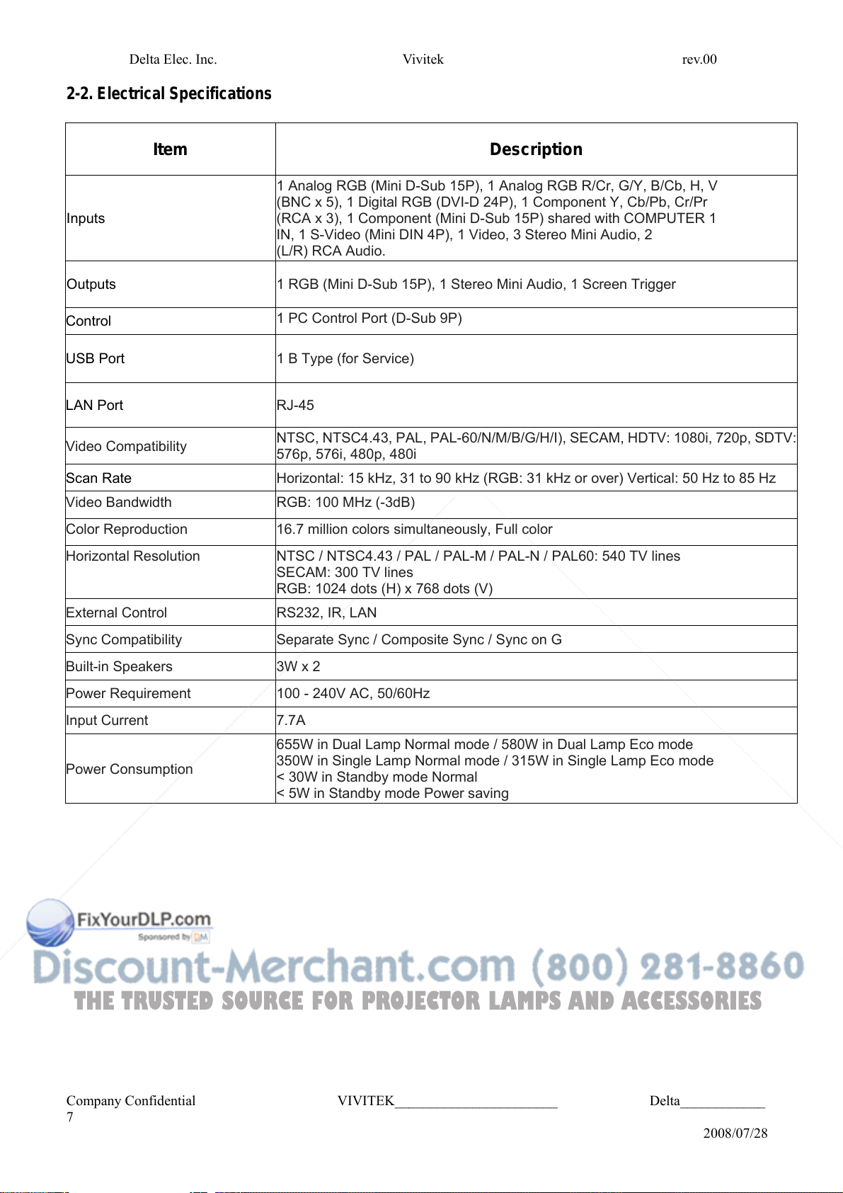
2-2. Electrical Specifications
Item Description
1 Analog RGB (Mini D-Sub 15P), 1 Analog RGB R/Cr, G/Y, B/Cb, H, V
(BNC x 5), 1 Digital RGB (DVI-D 24P), 1 Component Y, Cb/Pb, Cr/Pr
Inputs
Outputs 1 RGB (Mini D-Sub 15P), 1 Stereo Mini Audio, 1 Screen Trigger
(RCA x 3), 1 Component (Mini D-Sub 15P) shared with COMPUTER 1
IN, 1 S-Video (Mini DIN 4P), 1 Video, 3 Stereo Mini Audio, 2
(L/R) RCA Audio.
Control
USB Port 1 B Type (for Service)
LAN Port RJ-45
Video Compatibility
Scan Rate Horizontal: 15 kHz, 31 to 90 kHz (RGB: 31 kHz or over) Vertical: 50 Hz to 85 Hz
Video Bandwidth RGB: 100 MHz (-3dB)
Color Reproduction 16.7 million colors simultaneously, Full color
Horizontal Resolution
External Control RS232, IR, LAN
Sync Compatibility Separate Sync / Composite Sync / Sync on G
Built-in Speakers 3W x 2
Power Requirement 100 - 240V AC, 50/60Hz
Input Current 7.7A
Power Consumption
1 PC Control Port (D-Sub 9P)
NTSC, NTSC4.43, PAL, PAL-60/N/M/B/G/H/I), SECAM, HDTV: 1080i, 720p, SDTV:
576p, 576i, 480p, 480i
NTSC / NTSC4.43 / PAL / PAL-M / PAL-N / PAL60: 540 TV lines
SECAM: 300 TV lines
RGB: 1024 dots (H) x 768 dots (V)
655W in Dual Lamp Normal mode / 580W in Dual Lamp Eco mode
350W in Single Lamp Normal mode / 315W in Single Lamp Eco mode
< 30W in Standby mode Normal
< 5W in Standby mode Power saving
Company Confidential VIVITEK_______________________ Delta____________
7
2008/07/28
Delta Elec. Inc. Vivitek rev.00
THE TRUSTED SOURCE FOR PROJECTOR LAMPS AND ACCESSORIES
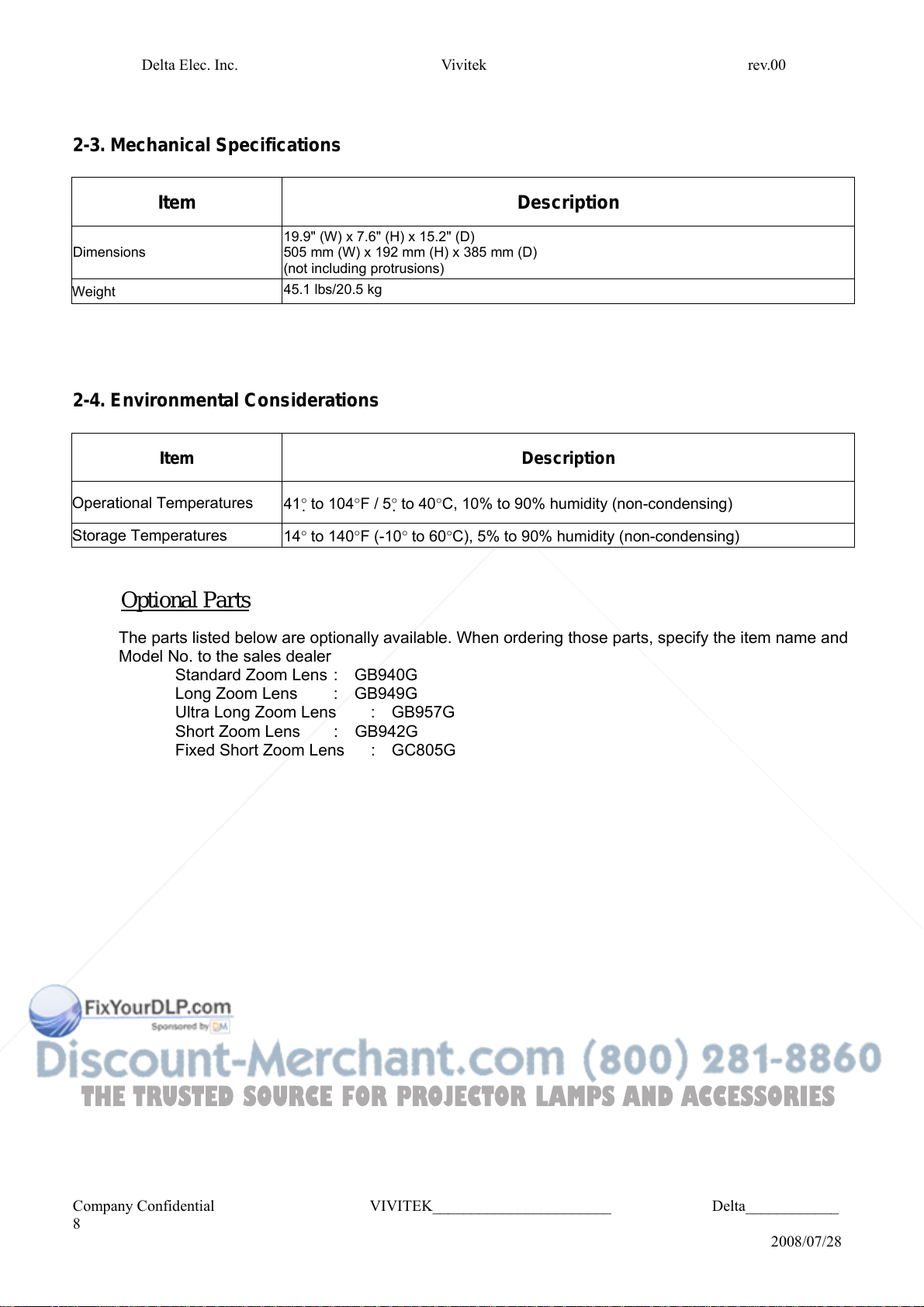
2-3. Mechanical Specifications
Item Description
19.9" (W) x 7.6" (H) x 15.2" (D)
Dimensions
Weight
505 mm (W) x 192 mm (H) x 385 mm (D)
(not including protrusions)
45.1 lbs/20.5 kg
2-4. Environmental Considerations
Item Description
Operational Temperatures
Storage Temperatures
41° to 104°F / 5° to 40°C, 10% to 90% humidity (non-condensing)
14° to 140°F (-10° to 60°C), 5% to 90% humidity (non-condensing)
Optional Parts
The parts listed below are optionally available. When ordering those parts, specify the item name and
Model No. to the sales dealer
Standard Zoom Lens : GB940G
Long Zoom Lens : GB949G
Ultra Long Zoom Lens : GB957G
Short Zoom Lens : GB942G
Fixed Short Zoom Lens : GC805G
Company Confidential VIVITEK_______________________ Delta____________
8
2008/07/28
Delta Elec. Inc. Vivitek rev.00
THE TRUSTED SOURCE FOR PROJECTOR LAMPS AND ACCESSORIES
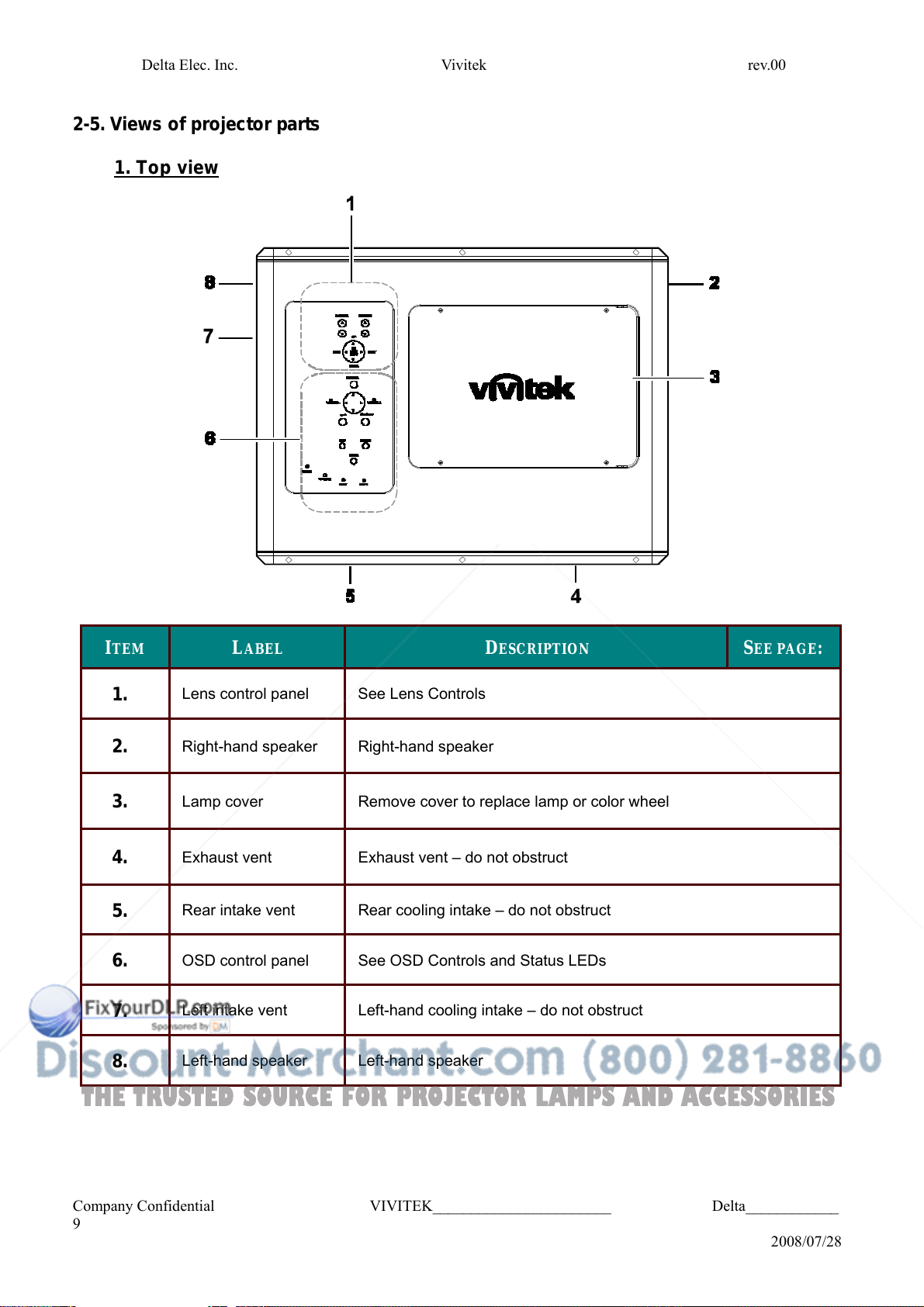
2-5. Views of projector parts
1. Top view
I
TEM
1.
2.
L
ABEL
Lens control panel
Right-hand speaker
See Lens Controls
Right-hand speaker
D
ESCRIPTION
S
EE PAGE
:
3.
Lamp cover
Remove cover to replace lamp or color wheel
4.
5.
6.
7.
8.
Company Confidential VIVITEK_______________________ Delta____________
9
Exhaust vent
Rear intake vent
OSD control panel
Left intake vent
Left-hand speaker
Exhaust vent – do not obstruct
Rear cooling intake – do not obstruct
See OSD Controls and Status LEDs
Left-hand cooling intake – do not obstruct
Left-hand speaker
2008/07/28
Delta Elec. Inc. Vivitek rev.00
THE TRUSTED SOURCE FOR PROJECTOR LAMPS AND ACCESSORIES
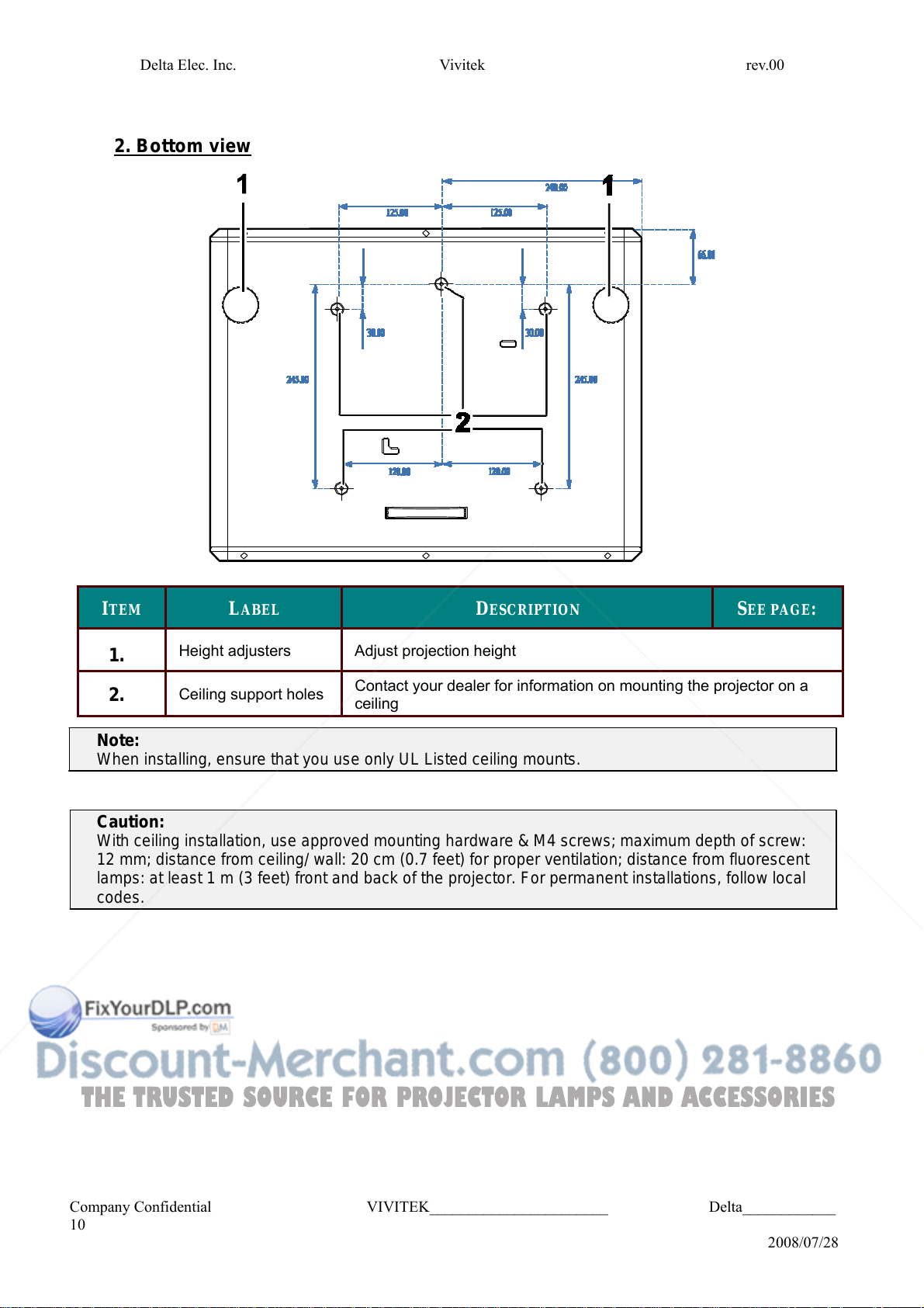
2. Bottom view
I
TEM
1.
2.
Note:
Height adjusters
Ceiling support holes
When installing, ensure that you use only UL Listed ceiling mounts.
Caution:
With ceiling installation, use approved mounting hardware & M4 screws; maximum depth of screw:
12 mm; distance from ceiling/ wall: 20 cm (0.7 feet) for proper ventilation; distance from fluorescent
lamps: at least 1 m (3 feet) front and back of the projector. For permanent installations, follow local
codes.
L
ABEL
Adjust projection height
D
ESCRIPTION
Contact your dealer for information on mounting the projector on a
ceiling
S
EE PAGE
:
Company Confidential VIVITEK_______________________ Delta____________
10
2008/07/28
Delta Elec. Inc. Vivitek rev.00
THE TRUSTED SOURCE FOR PROJECTOR LAMPS AND ACCESSORIES
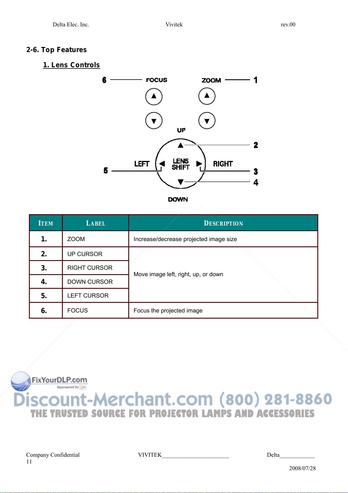
2-6. Top Features
1. Lens Controls
I
TEM
1.
2.
3.
4.
5.
6.
ZOOM
UP CURSOR
RIGHT CURSOR
DOWN CURSOR
LEFT CURSOR
FOCUS
L
ABEL
Increase/decrease projected image size
D
ESCRIPTION
Move image left, right, up, or down
Focus the projected image
Company Confidential VIVITEK_______________________ Delta____________
11
2008/07/28
Delta Elec. Inc. Vivitek rev.00
THE TRUSTED SOURCE FOR PROJECTOR LAMPS AND ACCESSORIES
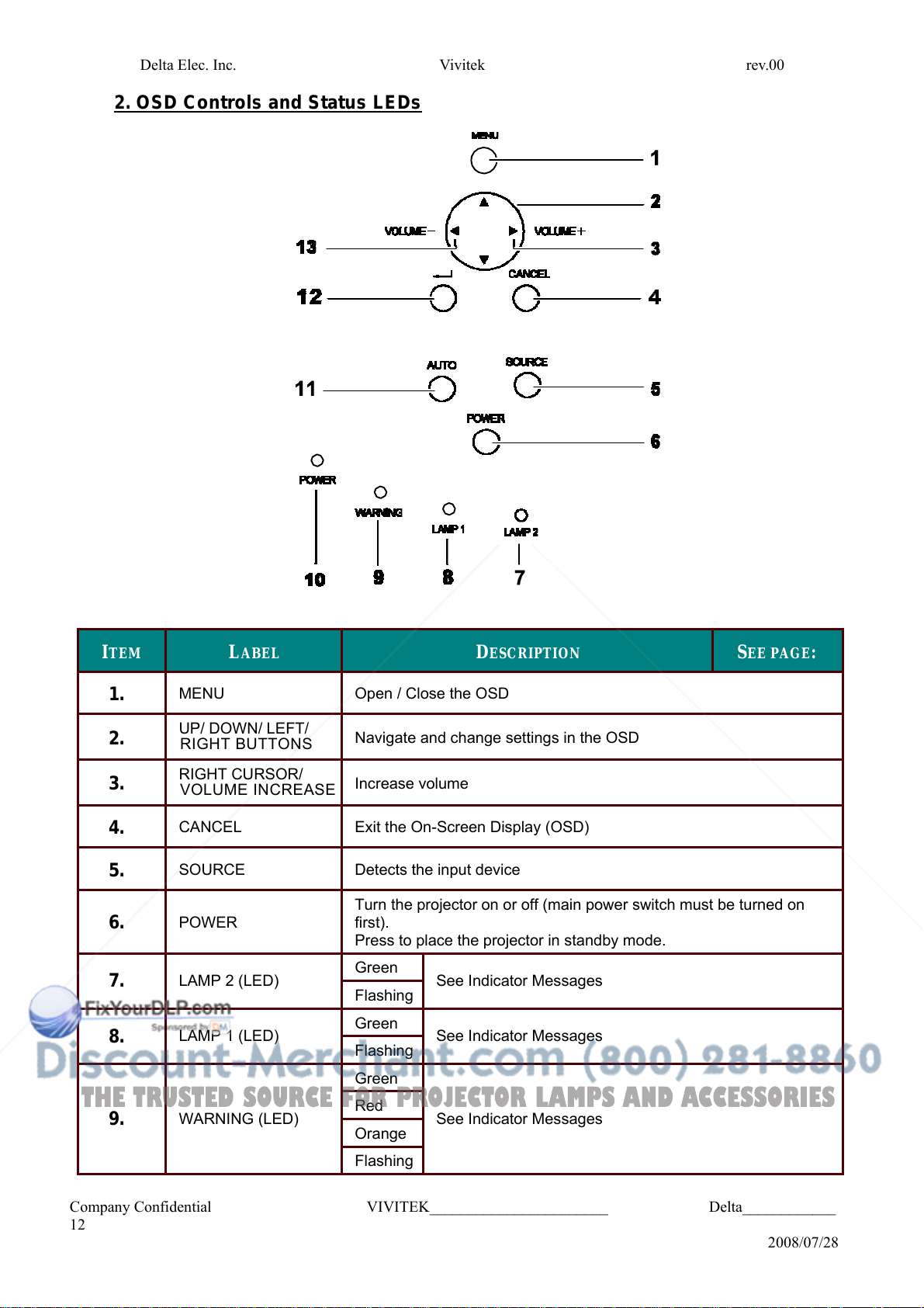
2. OSD Controls and Status LEDs
I
TEM
1.
2.
3.
4.
5.
6.
L
ABEL
MENU
UP/ DOWN/ LEFT/
RIGHT BUTTONS
RIGHT CURSOR/
VOLUME INCREASE
CANCEL
SOURCE
POWER
7.
8.
LAMP 2 (LED)
LAMP 1 (LED)
9.
WARNING (LED)
Company Confidential VIVITEK_______________________ Delta____________
12
Open / Close the OSD
D
ESCRIPTION
S
EE PAGE
:
Navigate and change settings in the OSD
Increase volume
Exit the On-Screen Display (OSD)
Detects the input device
Turn the projector on or off (main power switch must be turned on
first).
Press to place the projector in standby mode.
Green
See Indicator Messages
Flashing
Green
See Indicator Messages
Flashing
Green
Red
See Indicator Messages
Orange
Flashing
2008/07/28
Delta Elec. Inc. Vivitek rev.00
THE TRUSTED SOURCE FOR PROJECTOR LAMPS AND ACCESSORIES
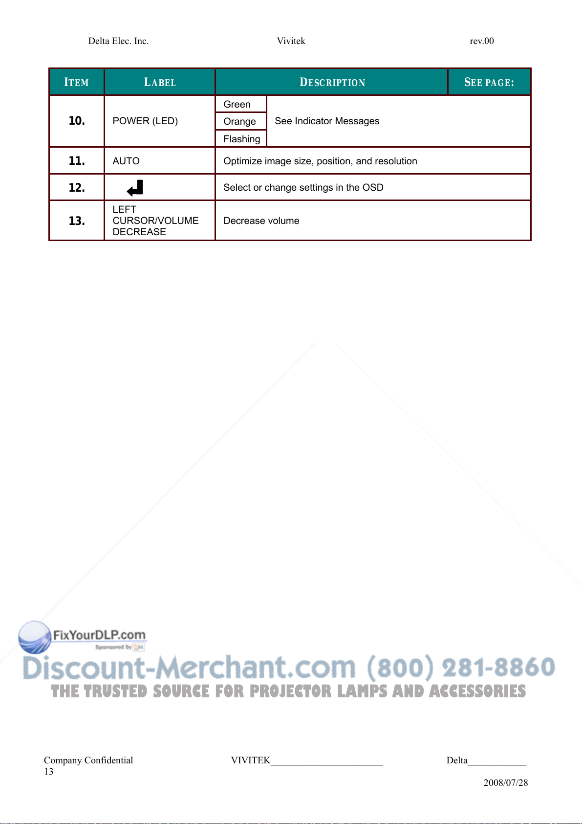
I
TEM
10.
11.
12.
13.
L
POWER (LED)
AUTO
LEFT
CURSOR/VOLUME
DECREASE
ABEL
Green
Orange
Flashing
Optimize image size, position, and resolution
Select or change settings in the OSD
D
ESCRIPTION
See Indicator Messages
S
EE PAGE
:
Decrease volume
Company Confidential VIVITEK_______________________ Delta____________
13
2008/07/28
Delta Elec. Inc. Vivitek rev.00
THE TRUSTED SOURCE FOR PROJECTOR LAMPS AND ACCESSORIES
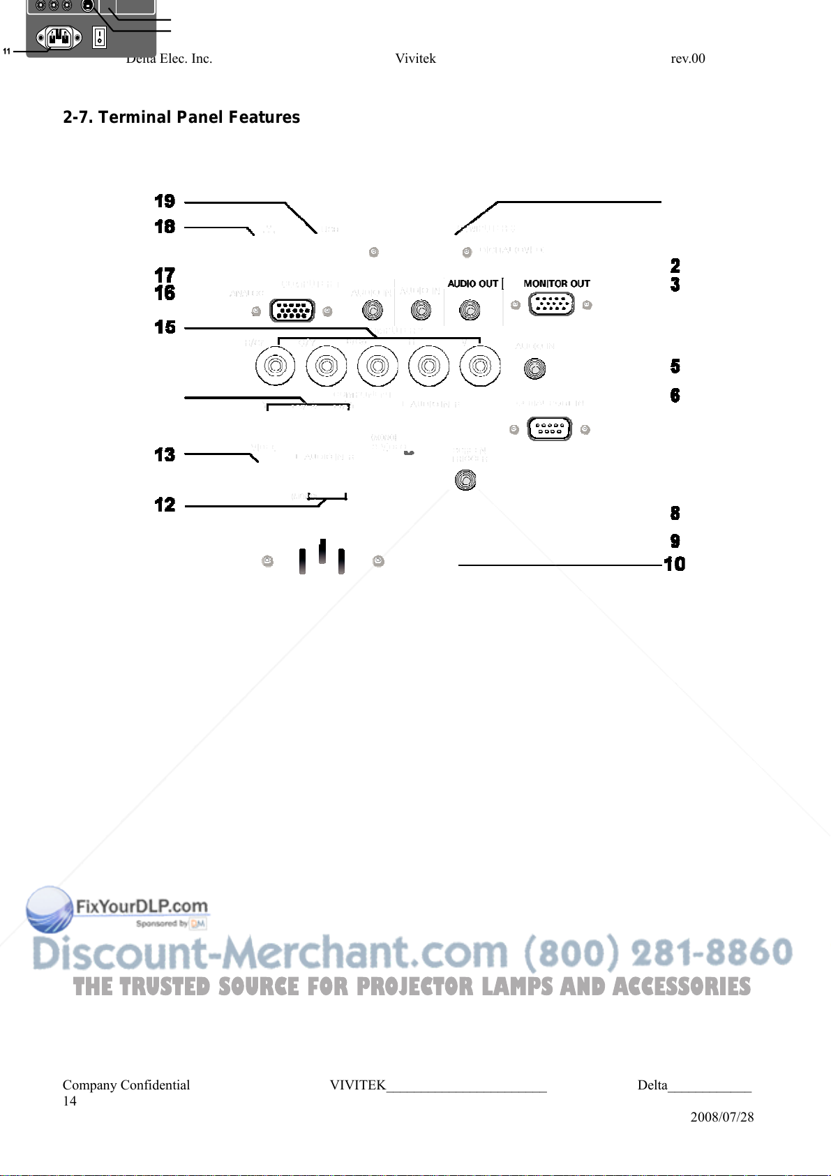
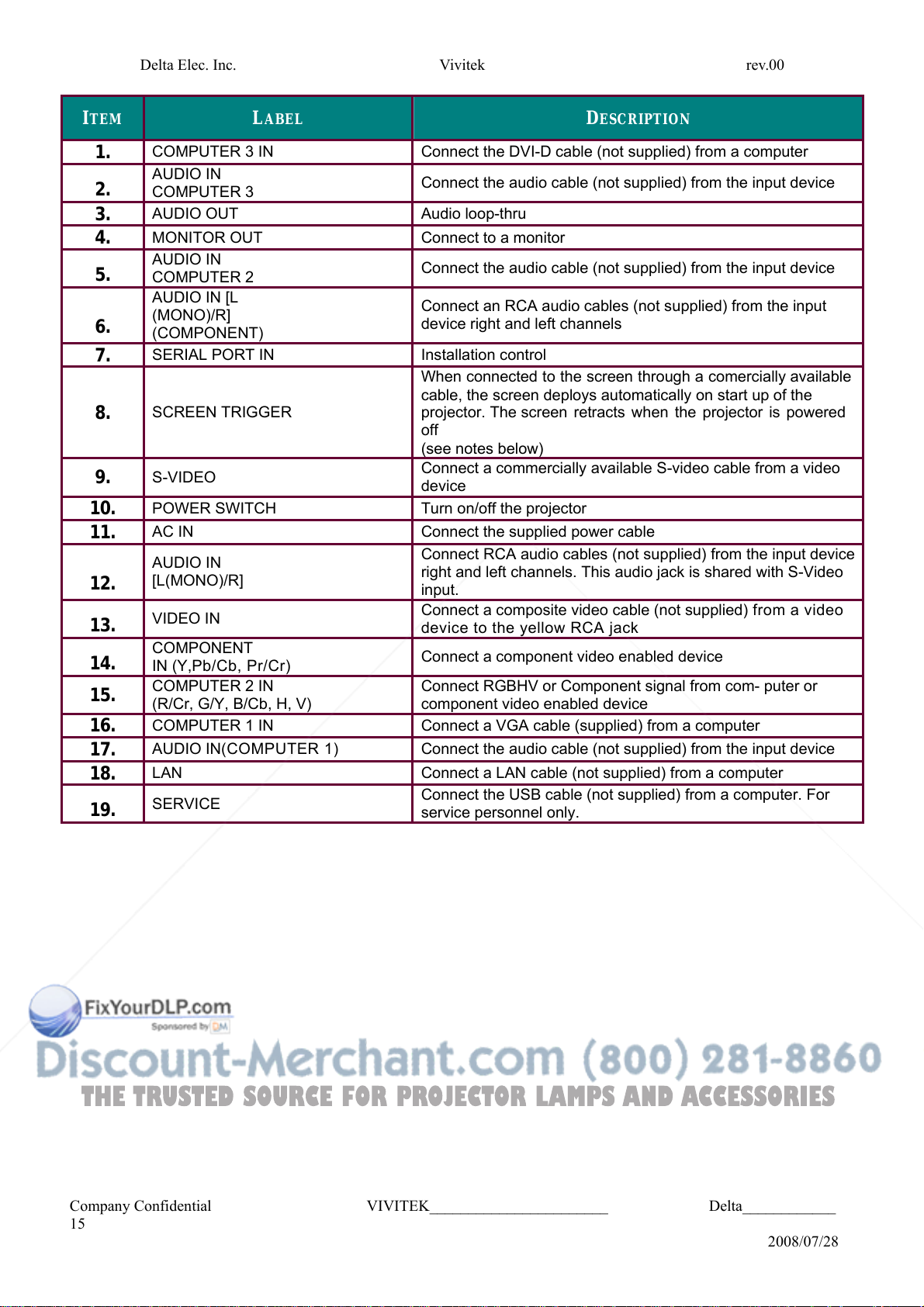
2-7. Terminal Panel Features
Company Confidential VIVITEK_______________________ Delta____________
14
2008/07/28
THE TRUSTED SOURCE FOR PROJECTOR LAMPS AND ACCESSORIES
Delta Elec. Inc. Vivitek rev.00
I
TEM
L
ABEL
D
ESCRIPTION
1.
2.
3.
4.
5.
6.
7.
8.
9.
10.
11.
12.
13.
14.
15.
16.
17.
18.
19.
COMPUTER 3 IN Connect the DVI-D cable (not supplied) from a computer
AUDIO IN
COMPUTER 3
AUDIO OUT Audio loop-thru
MONITOR OUT Connect to a monitor
AUDIO IN
COMPUTER 2
AUDIO IN [L
(MONO)/R]
(COMPONENT)
SERIAL PORT IN Installation control
SCREEN TRIGGER
S-VIDEO
POWER SWITCH Turn on/off the projector
AC IN Connect the supplied power cable
AUDIO IN
[L(MONO)/R]
VIDEO IN
COMPONENT
IN (Y,Pb/Cb, Pr/Cr)
COMPUTER 2 IN
(R/Cr, G/Y, B/Cb, H, V)
COMPUTER 1 IN Connect a VGA cable (supplied) from a computer
AUDIO IN(COMPUTER 1) Connect the audio cable (not supplied) from the input device
LAN Connect a LAN cable (not supplied) from a computer
SERVICE
Connect the audio cable (not supplied) from the input device
Connect the audio cable (not supplied) from the input device
Connect an RCA audio cables (not supplied) from the input
device right and left channels
When connected to the screen through a comercially available
cable, the screen deploys automatically on start up of the
projector. The screen retracts when the projector is powered
off
(see notes below)
Connect a commercially available S-video cable from a video
device
Connect RCA audio cables (not supplied) from the input device
right and left channels. This audio jack is shared with S-Video
input.
Connect a composite video cable (not supplied) from a video
device to the yellow RCA jack
Connect a component video enabled device
Connect RGBHV or Component signal from com- puter or
component video enabled device
Connect the USB cable (not supplied) from a computer. For
service personnel only.
Company Confidential VIVITEK_______________________ Delta____________
15
2008/07/28
Delta Elec. Inc. Vivitek rev.00
THE TRUSTED SOURCE FOR PROJECTOR LAMPS AND ACCESSORIES
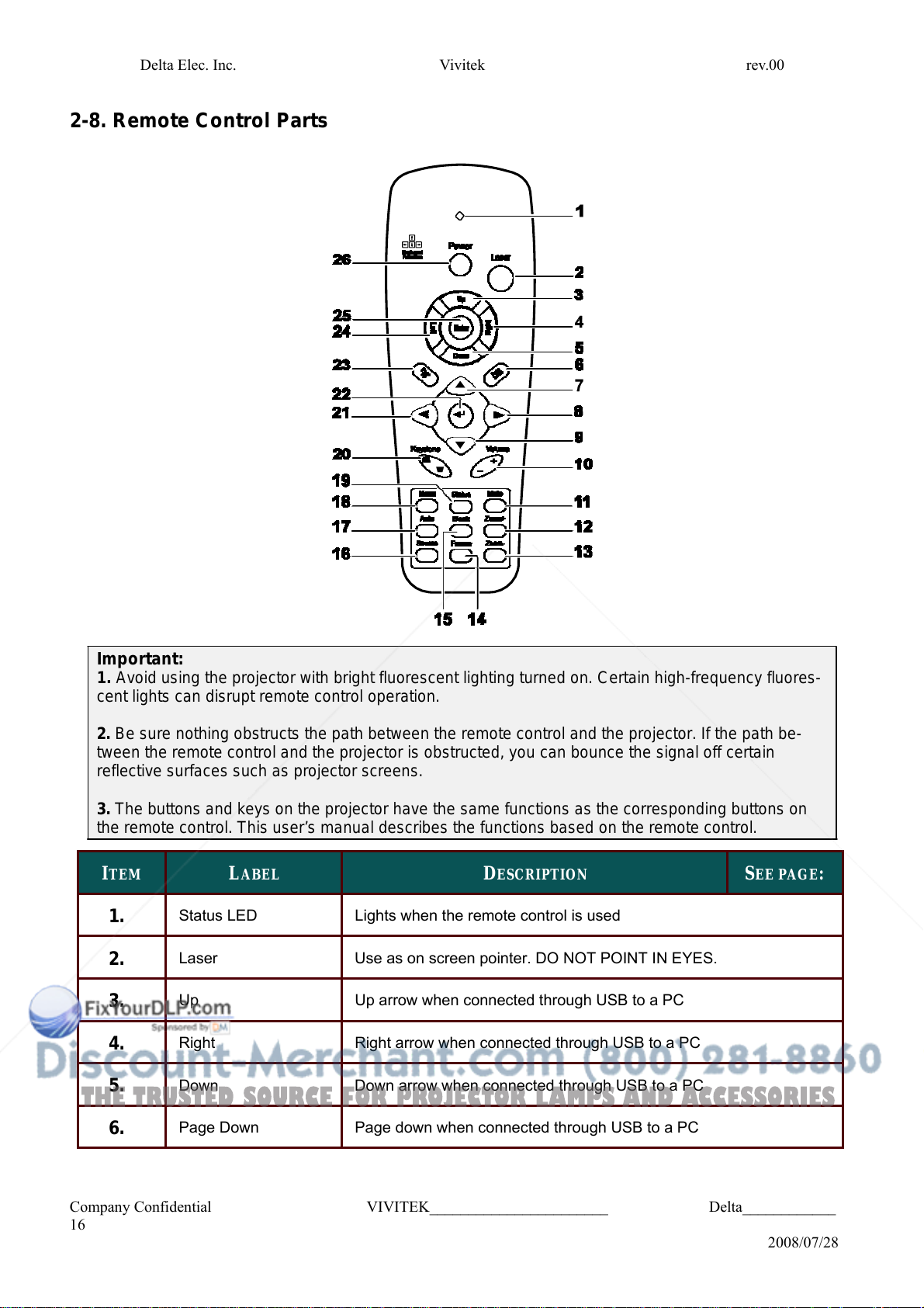
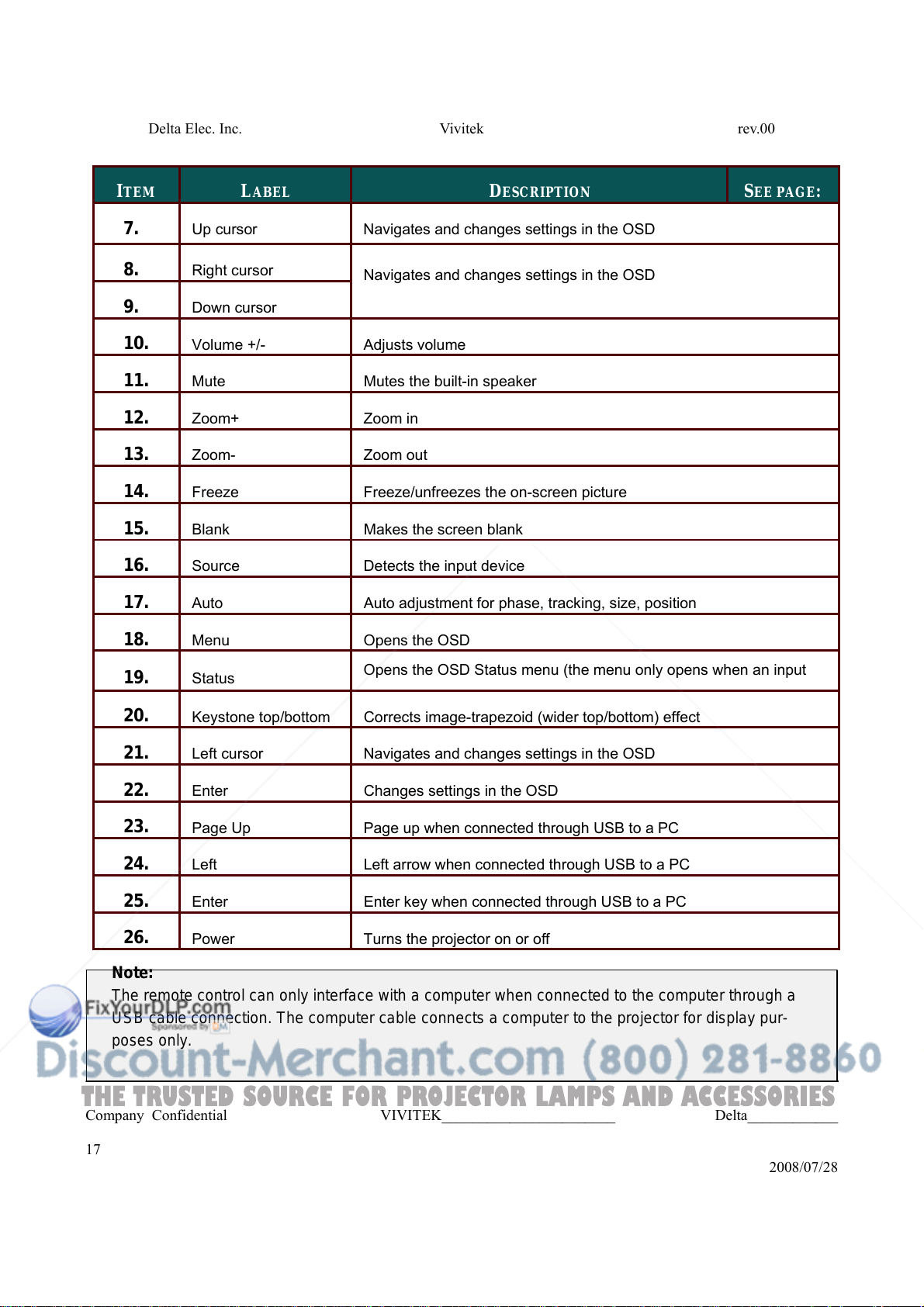
2-8. Remote Control Parts
Important:
1. Avoid using the projector with bright fluorescent lighting turned on. Certain high-frequency fluores-
cent lights can disrupt remote control operation.
2. Be sure nothing obstructs the path between the remote control and the projector. If the path be-
tween the remote control and the projector is obstructed, you can bounce the signal off certain
reflective surfaces such as projector screens.
3. The buttons and keys on the projector have the same functions as the corresponding buttons on
the remote control. This user’s manual describes the functions based on the remote control.
I
TEM
1.
2.
3.
4.
5.
6.
L
ABEL
Status LED
Laser
Up
Right
Down
Page Down
D
ESCRIPTION
S
EE PAGE
Lights when the remote control is used
Use as on screen pointer. DO NOT POINT IN EYES.
Up arrow when connected through USB to a PC
Right arrow when connected through USB to a PC
Down arrow when connected through USB to a PC
Page down when connected through USB to a PC
:
Company Confidential VIVITEK_______________________ Delta____________
16
2008/07/28
THE TRUSTED SOURCE FOR PROJECTOR LAMPS AND ACCESSORIES
Delta Elec. Inc. Vivitek rev.00
I
TEM
7.
8.
9.
10.
11.
12.
13.
14.
15.
16.
17.
18.
19.
20.
21.
22.
23.
24.
25.
26.
Note:
Up cursor
Right cursor
L
ABEL
D
ESCRIPTION
Navigates and changes settings in the OSD
Navigates and changes settings in the OSD
Down cursor
Volume +/-
Mute
Zoom+
Zoom-
Freeze
Blank
Source
Auto
Menu
Status
Adjusts volume
Mutes the built-in speaker
Zoom in
Zoom out
Freeze/unfreezes the on-screen picture
Makes the screen blank
Detects the input device
Auto adjustment for phase, tracking, size, position
Opens the OSD
Opens the OSD Status menu (the menu only opens when an input
Keystone top/bottom Corrects image-trapezoid (wider top/bottom) effect
Left cursor
Enter
Page Up
Left
Enter
Power
Navigates and changes settings in the OSD
Changes settings in the OSD
Page up when connected through USB to a PC
Left arrow when connected through USB to a PC
Enter key when connected through USB to a PC
Turns the projector on or off
S
EE PAGE
:
The remote control can only interface with a computer when connected to the computer through a
USB cable connection. The computer cable conn ect s a comput er t o the project or for display pur-
poses only.
Company Confidential VIVITEK_______________________ Delta____________
17
2008/07/28
Delta Elec. Inc. Vivitek rev.00
THE TRUSTED SOURCE FOR PROJECTOR LAMPS AND ACCESSORIES
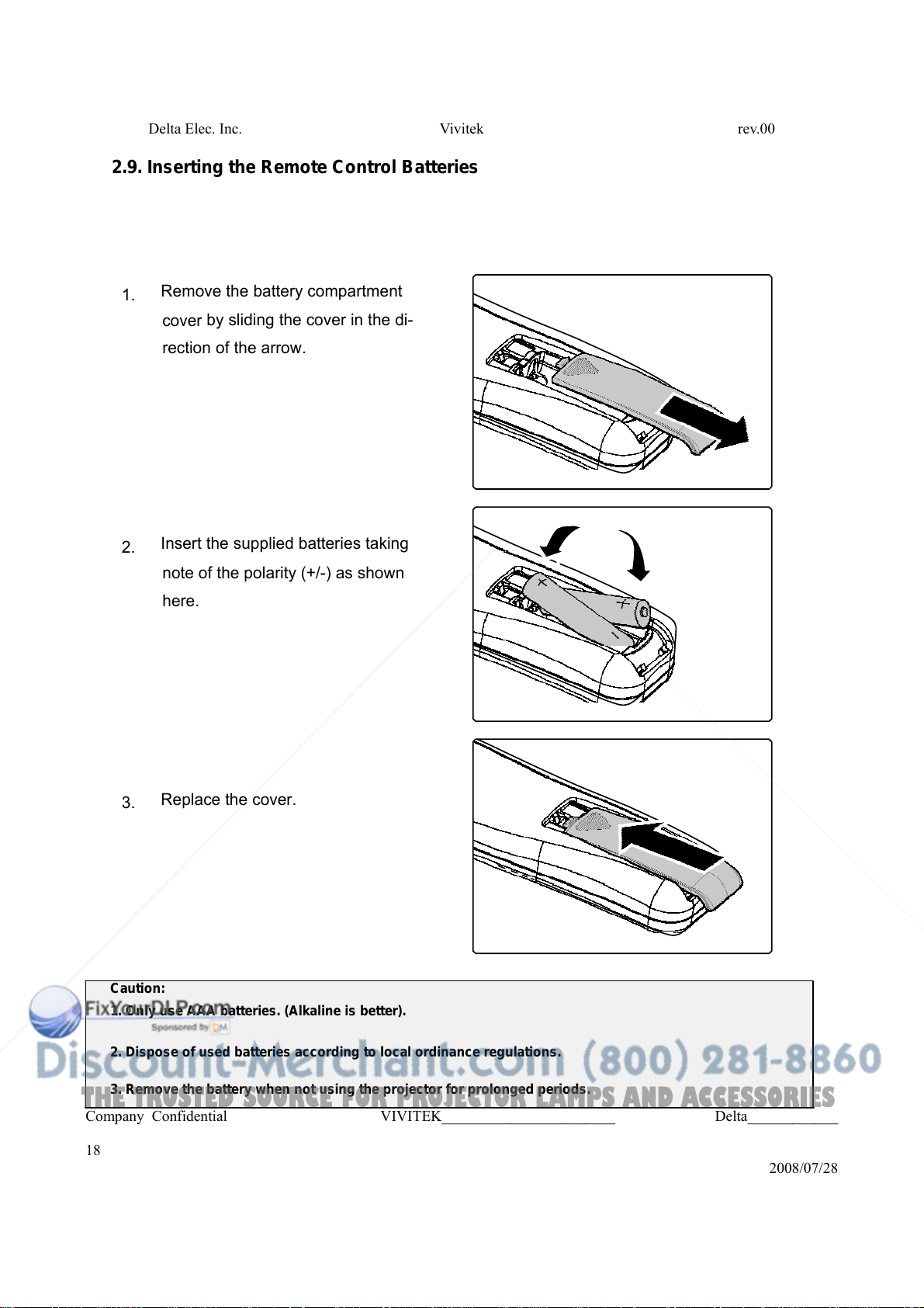
2.9. Inserting the Remote Control Batteries
Remove the battery compartment
1.
by
cover
rection
sliding the cover in the di-
of
the arrow.
Insert the supplied batteries taking
2.
of
note
the polarity (+/-) as shown
here.
Replace the cover.
3.
Caution:
1. Only use AAA batteries. (Alkaline is better).
2. Dispose of used batteries according to local ordinance regulations.
3. Remove the battery when not using the projector for prolonged periods.
Company Confidential VIVITEK_______________________ Delta____________
18
2008/07/28
Delta Elec. Inc. Vivitek rev.00
THE TRUSTED SOURCE FOR PROJECTOR LAMPS AND ACCESSORIES
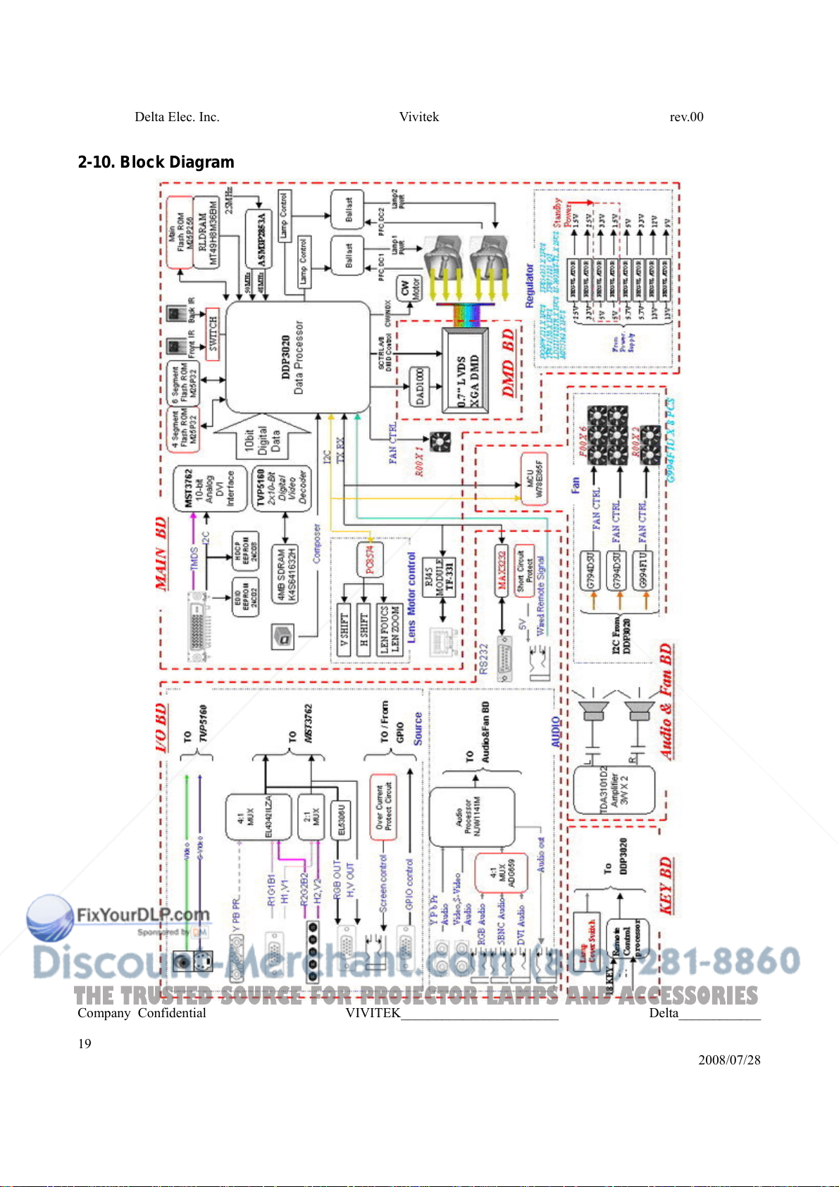
2-10. Block Diagram
Company Confidential VIVITEK_______________________ Delta____________
19
2008/07/28
Delta Elec. Inc. Vivitek rev.00
THE TRUSTED SOURCE FOR PROJECTOR LAMPS AND ACCESSORIES
2-11. Explanation of the block diagrams
1. Input signal processing
1-1.RGB & Component & DVI input system
The RGB(5BNC) and COMPONENT input signals are led through the multiplexer
circuit. After these signals and DVI signal have been converted into 10-bit digital signals
of RGB each at the A/D converter (U201) incorporated in the VIDEO amplifier, the
resultant signals are output to the scaler (U400).
1-2.Video input system
The VIDEO input and S-VIDEO input signals are decoded into the Y/CbCr (brightness
and chroma) signals at the video decoder (U702). The decoded signals are further
converted into 10-bit digital signals of Y/ CbCr, and then output to the scaler (U400).
2. Digital video signal processing
2-1.Scaler (U400)
• The Y/CbCr signals are processed for picture quality improvement and matrix
processing at the Scaler circuit, and then converted into the RGB signals.
• The RGB and VIDEO input signals are switched over at the selector. After passing
through the signal adjusting circuit of color space processing, auto-adjustment, etc.,
these signals are written in the RLDRAM.
• The video signals called up from the RLDRAM, pass through the definition converter
circuit, ON-screen display, error diffusion circuit for DLP, V-T compensator circuit, and
such signal processing circuits, and are then output to the optical engine unit (DLP
formatter board).
• In the frame memory consisting of the RLDRAM and the FIFO located in the scaler,
frequency conversion is conducted for the WRITE system and the READ system.
Therefore, the video signals can be output to the optical engine unit (DLP formatter
board) always at the constant timing.
• According to the conditions of projector installation, the trapezoidal distortion
compensation of the video signals are also effected through the frame memory.
Company Confidential VIVITEK_______________________ Delta____________
20
2008/07/28
Delta Elec. Inc. Vivitek rev.00
THE TRUSTED SOURCE FOR PROJECTOR LAMPS AND ACCESSORIES
3. Audio signal processing
• The audio output is generated from the speakers via the amplifier (U900) provided with a
volume control.
• The volume control is conducted by the DC output from the D/A converter (U900).
4. System control
The scaler (U400) controls all of this system.
5. Power circuit
1. Main power supply
• In the state of standby, the power is supplied 5V to the scaler, scaler peripheral ICs,
and FLASHROM.
• After the power is ON, the power at 2.5V, 3.3V, 5.7Vand 13V is fed to the analog circuit,
fan, formatter board, etc.
2. Lamp power supply
• The lamp is lit with POWER ON.
• Unlighting detection is performed.
6. Safety design
• Fan circuit detection
• Lamp cover detection
• Lamp house temperature detection
• Thermal protector for the lamp power supply
• Lamp replacing time
Company Confidential VIVITEK_______________________ Delta____________
21
2008/07/28

Delta Elec. Inc. Vivitek rev.00
THE TRUSTED SOURCE FOR PROJECTOR LAMPS AND ACCESSORIES
2-12. Wire Location
Company Confidential VIVITEK_______________________ Delta____________
22
2008/07/28
Delta Elec. Inc. Vivitek rev.00
THE TRUSTED SOURCE FOR PROJECTOR LAMPS AND ACCESSORIES
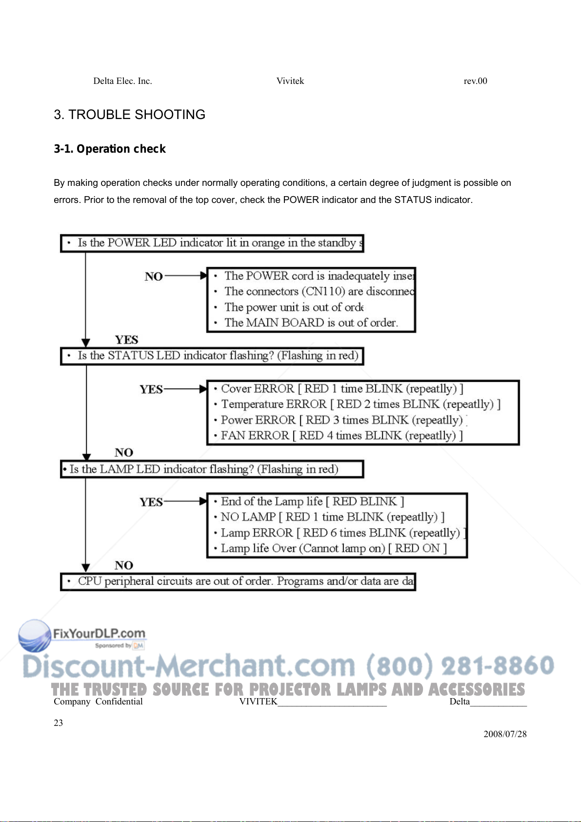
3. TROUBLE SHOOTING
3-1. Operation check
By making operation checks under normally operating conditions, a certain degree of judgment is possible on
errors. Prior to the removal of the top cover, check the POWER indicator and the STATUS indicator.
Company Confidential VIVITEK_______________________ Delta____________
23
2008/07/28
Delta Elec. Inc. Vivitek rev.00
THE TRUSTED SOURCE FOR PROJECTOR LAMPS AND ACCESSORIES
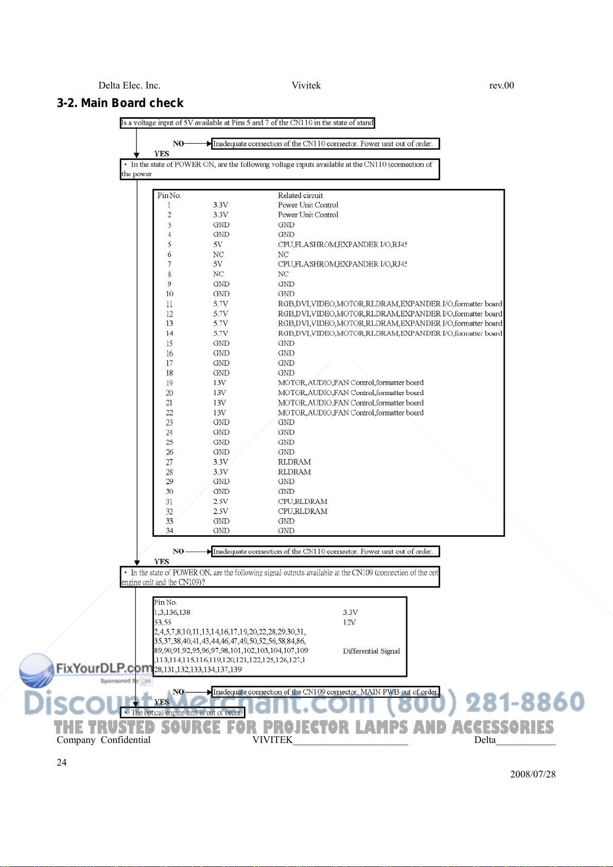
3-2. Main Board check
Company Confidential VIVITEK_______________________ Delta____________
24
2008/07/28
Delta Elec. Inc. Vivitek rev.00
THE TRUSTED SOURCE FOR PROJECTOR LAMPS AND ACCESSORIES
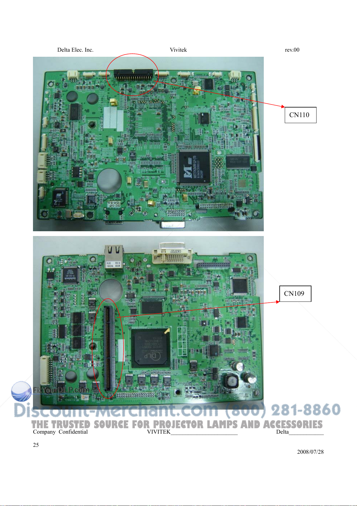
CN110
CN109
Company Confidential VIVITEK_______________________ Delta____________
25
2008/07/28
Delta Elec. Inc. Vivitek rev.00
THE TRUSTED SOURCE FOR PROJECTOR LAMPS AND ACCESSORIES
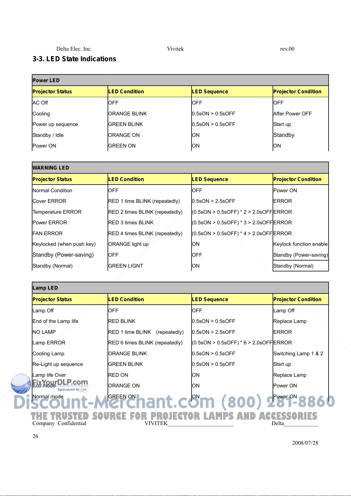
3-3. LED State Indications
Power LED
Projector Status LED Condition LED Sequence Projector Condition
AC Off OFF OFF OFF
Cooling ORANGE BLINK 0.5sON > 0.5sOFF After Power OFF
Power up sequence GREEN BLINK 0.5sON > 0.5sOFF Start up
Standby / Idle ORANGE ON ON
Power ON GREEN ON ON ON
WARNING LED
Projector Status LED Condition LED Sequence Projector Condition
Normal Condition OFF OFF Power ON
Cover ERROR RED 1 time BLINK (repeatedly) 0.5sON > 2.5sOFF ERROR
Temperature ERROR RED 2 times BLINK (repeatedly) (0.5sON > 0.5sOFF) * 2 > 2.0sOFF ERROR
Power ERROR RED 3 times BLINK (0.5sON > 0.5sOFF) * 3 > 2.0sOFF ERROR
FAN ERROR RED 4 times BLINK (repeatedly) (0.5sON > 0.5sOFF) * 4 > 2.0sOFF ERROR
Keylocked (when push key) ORANGE light up ON Keylock function enable
Standby (Power-saving)
Standby (Normal) GREEN LIGNT ON Standby (Normal)
Lamp LED
Projector Status LED Condition LED Sequence Projector Condition
OFF OFF Standby (Power-saving)
Standby
Lamp Off OFF OFF Lamp Off
End of the Lamp life RED BLINK 0.5sON > 0.5sOFF Replace Lamp
NO LAMP RED 1 time BLINK (repeatedly) 0.5sON > 2.5sOFF ERROR
Lamp ERROR RED 6 times BLINK (repeatedly) (0.5sON > 0.5sOFF) * 6 > 2.0sOFF ERROR
Cooling Lamp ORANGE BLINK 0.5sON > 0.5sOFF Switching Lamp 1 & 2
Re-Light up sequence GREEN BLINK 0.5sON > 0.5sOFF Start up
Lamp life Over RED ON ON Replace Lamp
Eco mode ORANGE ON ON Power ON
Normal mode GREEN ON ON Power ON
Company Confidential VIVITEK_______________________ Delta____________
26
2008/07/28
THE TRUSTED SOURCE FOR PROJECTOR LAMPS AND ACCESSORIES
Delta Elec. Inc. Vivitek rev.00
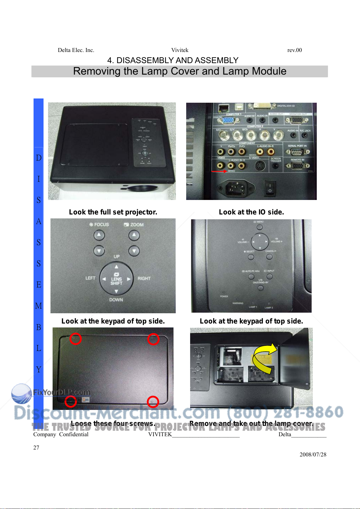
4. DISASSEMBLY AND ASSEMBLY
Removing the Lamp Cover and Lamp Module
D
I
S
A
S
S
E
M
B
L
Y
Look the full set projector. Look at the IO side.
Look at the keypad of top side. Look at the keypad of top side.
Loose these four screws. Remove and take out the lamp cover.
Company Confidential VIVITEK_______________________ Delta____________
27
2008/07/28
THE TRUSTED SOURCE FOR PROJECTOR LAMPS AND ACCESSORIES
Delta Elec. Inc. Vivitek rev.00
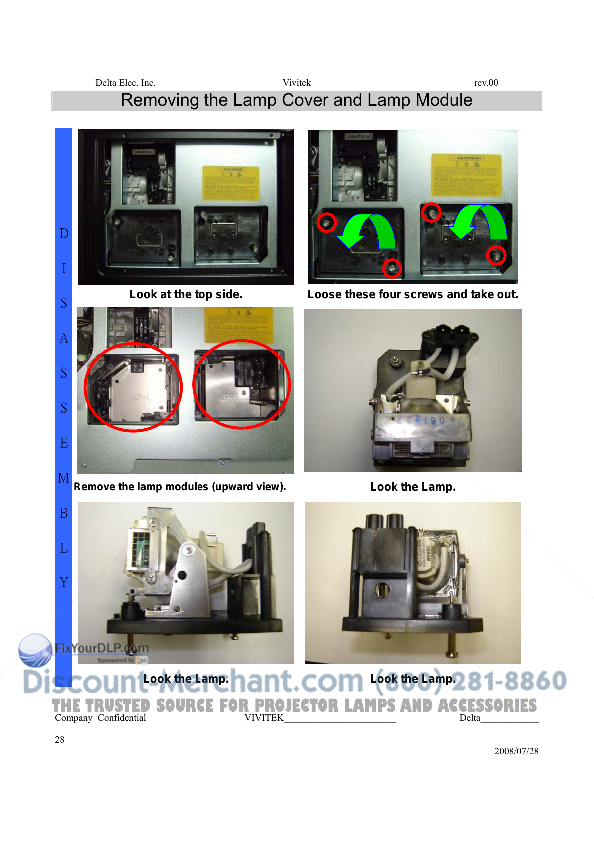
Removing the Lamp Cover and Lamp Module
D
I
S
Look at the top side. Loose these four screws and take out.
A
S
S
E
M
Remove the lamp modules (upward view).
B
L
Y
Look the Lamp.
Look the Lamp. Look the Lamp.
Company Confidential VIVITEK_______________________ Delta____________
28
2008/07/28
THE TRUSTED SOURCE FOR PROJECTOR LAMPS AND ACCESSORIES
Delta Elec. Inc. Vivitek rev.00
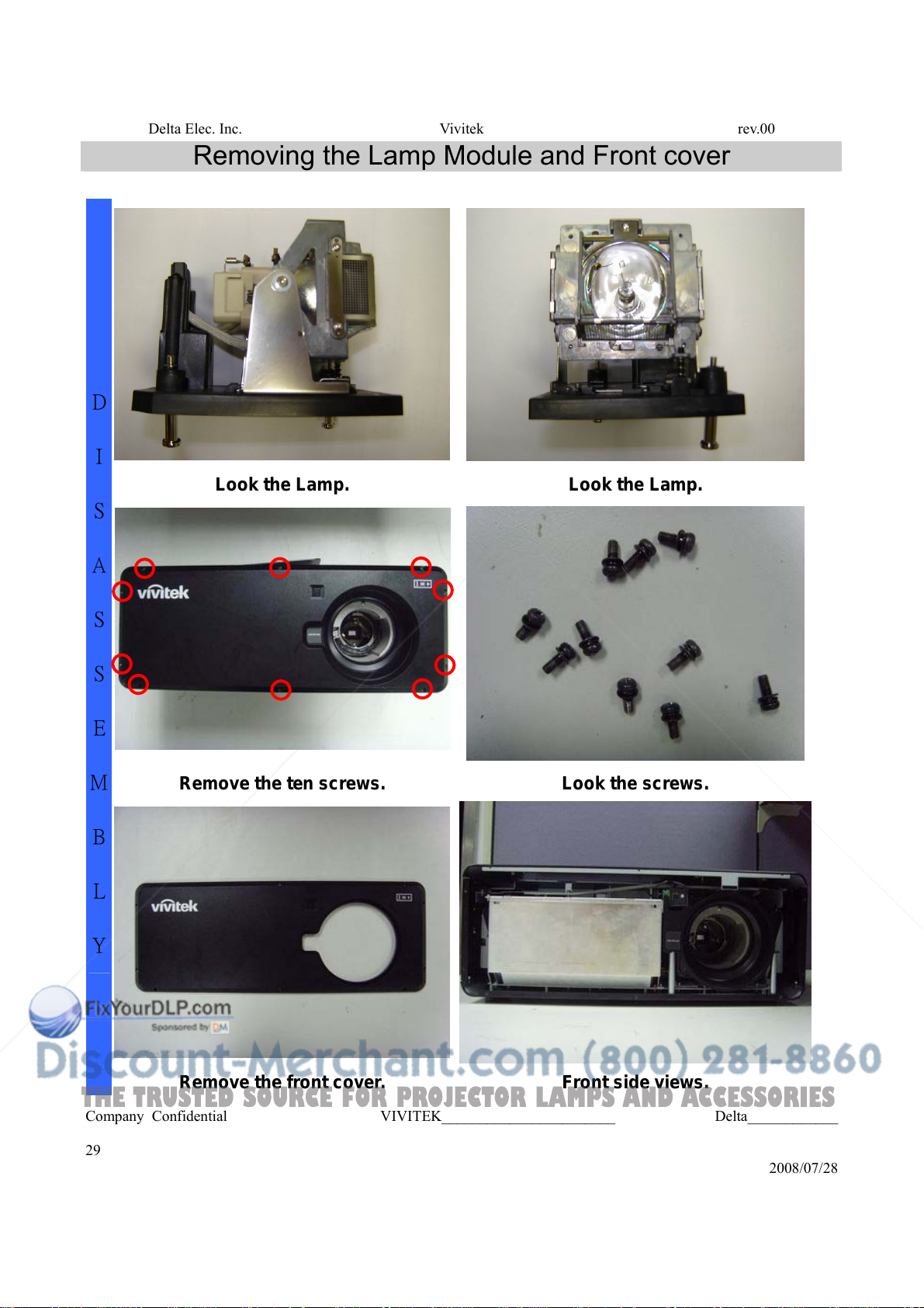
Removing the Lamp Module and Front cover
D
S
A
S
S
E
M
B
L
I
Look the Lamp. Look the Lamp.
Remove the ten screws. Look the screws.
Y
Remove the front cover. Front side views.
Company Confidential VIVITEK_______________________ Delta____________
29
2008/07/28
 Loading...