

Page 1
Page 2

Copyright
This publication, including all photographs, illustrations and software, is protected under international
copyright laws, with all rights reserved. Neither this manual, nor any of the material contained herein, may
be reproduced without written consent of the author.
© Copyright 2013
Disclaimer
The information in this document is subject to change without notice. The manufacturer makes no
representations or warranties with respect to the contents hereof and specifically disclaims any implied
warranties of merchantability or fitness for any particular purpose. The manufacturer reserves the right to
revise this publication and to make changes from time to time in the content hereof without obligation of
the manufacturer to notify any person of such revision or changes.
Trademark Recognition
Kensington is a U.S. registered trademark of ACCO Brand Corporation with issued registrations
and pending applications in other countries throughout the world.
HDMI, the HDMI Logo, and High-Definition Multimedia Interface are trademarks or
registered trademarks of HDMI Licensing LLC in the United States and other countries.
All other product names used in this manual are the properties of their respective owners and are
acknowledged.
— i —
Page 3
DLP Projector—User’s Manual
Important Safety Information
Important:
It is strongly recommended that you read this section carefully before using the projector. These
safety and usage instructions will ensure that you enjoy many years of safe use of the projector.
Keep this manual for future reference.
Symbols Used
Warning symbols are used on the unit and in this manual to alert you of hazardous situations.
The following styles are used in this manual to alert you to important information.
Note:
Provides additional information on the topic at hand.
Important:
Provides additional information that should not be overlooked.
Caution:
Alerts you to situations that may damage the unit.
Warning:
Alerts you to situations that may damage the unit, create a hazardous environment, or cause
personal injury.
Throughout this manual, component parts and items in the OSD menus are denoted in bold font as in this
example:
“Push the Menu button on the remote control to open the Main menu.”
General Safety Information
¾ Do not open the unit case. Aside from the projection lamp, there are no user-serviceable parts in
the unit. For servicing, contact qualified service personnel.
¾ Follow all warnings and cautions in this manual and on the unit case.
¾ The projection lamp is extremely bright by design. To avoid damage to eyes, do not look into the
lens when the lamp is on.
¾ Do not place the unit on an unstable surface, cart, or stand.
¾ Avoid using the system near water, in direct sunlight, or near a heating device.
¾ Do not place heavy objects such as books or bags on the unit.
— ii —
Page 4
Projector Installation Notice
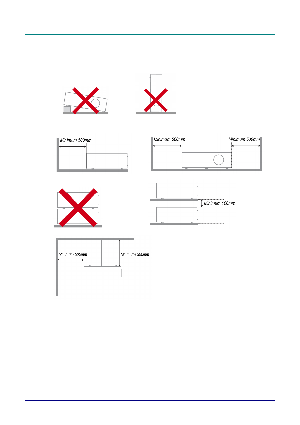
¾ Place the projector in a horizontal position
The tilt angle of the projector please see Tilt Up/Down caution on page 52.
P
r
e
f
a
c
e
P
r
P
r
e
f
a
c
e
e
f
a
c
e
¾ Allow at least 50 cm clearance around the exhaust vent.
¾ Ensure that the intake vents do not recycle hot air from the exhaust vent.
¾ When operating the projector in an enclosed space, ensure that the surrounding air temperature
within the enclosure does not exceed operation temperature while the projector is running, and the
air intake and exhaust vents are unobstructed.
¾ All enclosures should pass a certified thermal evaluation to ensure that the projector does not
recycle exhaust air, as this may cause the device to shutdown even if the enclosure temperature is
with the acceptable operation temperature range.
– iii –
Page 5

DLP Projector—User’s Manual
Verify Installation Location
¾ To supply power, the 3-blade (with earthing lead) socket should be used to ensure proper
grounding and equalized ground potential for all of the equipment in the Projector System.
¾ The power code provided with the Projector should be used. In case of any missing item, other
qualified 3-blade (with earthing lead) power cord can be used as substitution; however, do not use
2-blade power cord.
¾ Verify if the voltage is stable, grounded properly and there is no electricity leakage.
¾ Measure total power consumption which should not higher the safety capacity and avoid safety
issue and short circuit.
¾ Turn on Altitude Mode when located in high altitude areas
¾ When installation the bracket, make sure the weight limit is not exceed and firmly secured.
¾ Avoid installing near air conditioner duct or subwoofer.
¾ Avoid installing at high temperature, insufficient cooling and heavy dust locations.
¾ Keep your product away from fluorescent lamps to avoid malfunction
caused by IR interference
¾ The VGA IN connector should be connected to the VGA IN port. Note that it should be inserted
tightly, with the screws on both sides securely fastened to ensure proper connection of the signal
wire for achieving optimal display effect.
¾ The AUDIO IN connector should be connected to the AUDIO IN port and CANNOT be connected
to AUDIO OUT or other ports like BNC, RCA; otherwise, it will lead to mute output and even
DAMAGE the port.
¾ Install the projector above 200cm to avoid damage.
¾ The power cord and signal cable should be connected before power on the projector. During the
projector starting and operating process, DO NOT insert or remove the signal cable or the power
cord to avoid damaging the projector.
Cooling notes
Air outlet
¾ Make sure the air outlet is 50cm clear of any obstruction to ensure proper cooling.
¾ Air outlet location should not be in front of the lens of other projector to avoid causing illusions.
¾ Keep the outlet at least 100cm away from the inlets of other projectors
¾ The projector generates a massive amount of heat during use. The internal fan dissipates the heat
of the projector when shutting down, and such process may continue for a certain period. After the
project enters STANDBY MODE status, press the AC power button to turn off the projector and
remove the power cord. DO NOT remove the power cord during the shutdown process, as it may
cause damage to the projector. In the meantime, the delayed heat radiating will also affect the
service life of the projector. The shutdown process may vary depending on the model used.
Whatever the case may be, be sure to disconnect the power cord till after the projector enters the
STANDBY status.
Air inlet
¾ Make sure there is no object blocking air input within 30 cm.
¾ Keep the inlet away from other heat sources
¾ Avoided heavy dust area
— iv —
Page 6

Power Safety
¾ Only use the supplied power cord.
¾ Do not place anything on the power cord. Place the power cord where it will not be in the way of
foot traffic.
¾ Remove the batteries from the remote control when storing or not in use for a prolonged period.
Replacing the Lamp
Replacing the lamp can be hazardous if done incorrectly. See Replacing the Projection Lamp on page 54
for clear and safe instructions for this procedure. Before replacing the lamp:
¾ Unplug the power cord.
¾ Allow the lamp to cool for about one hour.
Caution:
In rare cases the lamp bulb may burn out during normal operation and cause glass dust or shards
to be discharged outward from the rear exhaust vent.
Do not inhale or do not touch glass dust or shards. Doing so could result in injury.
Always keep your face away from the exhaust vent so that you do not suffer from the gas and
broken shards of the lamp.
P
r
P
r
P
e
f
a
c
e
e
f
a
c
e
r
e
f
a
c
e
Cleaning the Projector
¾ Unplug the power cord before cleaning. See Cleaning the Projector on page 60.
¾ Allow the lamp to cool for about one hour.
Regulatory Warnings
Before installing and using the projector, read the regulatory notices in the Regulatory Compliance on
page 80.
Important Recycle Instructions:
Lamp(s) inside this product contain mercury. This product may contain other electronic waste that
can be hazardous if not disposed of properly. Recycle or dispose in accordance with local, state, or federal
Laws. For more information, contact the Electronic Industries Alliance at WWW.EIAE.ORG
specific disposal information check WWW.LAMPRECYCLE.ORG.
Symbol Explanations
DISPOSAL: Do not use household or municipal waste collection services for
disposal of electrical and electronic equipment. EU countries require the use
of separate recycling collection services.
. For lamp
– v –
Page 7

DLP Projector—User’s Manual
Main Features
• Lightweight unit, easy to pack away and transport.
• Compatible with all major video standards including NTSC, PAL, and SECAM.
• A high brightness rating allows for presentations in daylight or in lit rooms.
• Supports resolutions up to WUXGA at 16.7 million colors to deliver crisp, clear images.
• Flexible setup allows for front, rear projections.
• Line-of-vision projections remain square, with advanced keystone correction for angled
projections.
• Input source automatically detected.
About this Manual
This manual is intended for end users and describes how to install and operate the DLP projector.
Wherever possible, relevant information—such as an illustration and its description—has been kept on
one page. This printer-friendly format is both for your convenience and to help save paper, thereby
protecting the environment. It is suggested that you only print sections that are relevant to your needs.
— vi —
Page 8

P
r
e
f
a
c
P
P
e
r
e
f
a
c
r
e
f
a
c
Table of Contents
GETTING STARTED........................................................................................................................................................... 1
PACKING CHECKLIST ........................................................................................................................................................... 1
VIEWS OF PROJECTOR PARTS............................................................................................................................................... 2
Front-right View ............................................................................................................................................................ 2
Top view—On-screen Display (OSD) buttons and LEDs....................................................................................... 3
Rear view....................................................................................................................................................................... 4
Bottom view................................................................................................................................................................... 6
REMOTE CONTROL PARTS ................................................................................................................................................... 7
REMOTE CONTROL OPERATING RANGE ............................................................................................................................... 9
PROJECTOR AND REMOTE CONTROL BUTTONS.................................................................................................................... 9
SETUP AND OPERATION............................................................................................................................................... 10
INSERTING THE REMOTE CONTROL BATTERIES ................................................................................................................. 10
INSTALLING OR REMOVING THE OPTIONAL LENS .............................................................................................................. 11
Removing the Existing Lens From the Projector ................................................................................................... 11
Installing the New Lens ............................................................................................................................................. 12
STARTING AND SHUTTING DOWN THE PROJECTOR............................................................................................................. 13
SETTING AN ACCESS PASSWORD (SECURITY LOCK) .......................................................................................................... 15
ADJUSTING THE PROJECTOR LEVEL ................................................................................................................................... 17
ADJUSTING PROJECTED IMAGE POSITION USING SHIFT ..................................................................................................... 18
Adjusting the vertical image position....................................................................................................................... 18
Adjusting the horizontal image position .................................................................................................................. 20
Shift Range Diagram ................................................................................................................................................. 20
ADJUSTING THE ZOOM, FOCUS AND KEYSTONE ................................................................................................................ 22
ADJUSTING THE VOLUME .................................................................................................................................................. 23
e
e
ON-SCREEN DISPLAY (OSD) MENU SETTINGS ...................................................................................................... 24
OSD MENU CONTROLS ..................................................................................................................................................... 24
Navigating the OSD ................................................................................................................................................... 24
SETTING THE OSD LANGUAGE .......................................................................................................................................... 25
OSD MENU OVERVIEW ..................................................................................................................................................... 26
IMAGE MENU..................................................................................................................................................................... 27
Computer Menu.......................................................................................................................................................... 28
Advanced Feature...................................................................................................................................................... 29
Color Manager ............................................................................................................................................................ 30
SETTINGS 1 MENU ............................................................................................................................................................. 31
Audio ............................................................................................................................................................................ 32
Advanced 1 Feature................................................................................................................................................... 33
Advanced 2 Feature................................................................................................................................................... 35
SETTINGS 2 MENU ............................................................................................................................................................. 36
Status ........................................................................................................................................................................... 37
Advanced 1 Feature................................................................................................................................................... 38
Advanced 2 Feature................................................................................................................................................... 50
MAINTENANCE AND SECURITY.................................................................................................................................. 52
TILT UP/DOWN CAUTION................................................................................................................................................... 52
The model with Standard lamp module .................................................................................................................. 52
The model with Tilt lamp module ............................................................................................................................. 52
REPLACING THE PROJECTION LAMP................................................................................................................................... 54
Resetting the Lamp.................................................................................................................................................... 57
CLEANING THE FILTER (FILTER: OPTIONAL PARTS) ............................................................................................................ 58
REPLACING THE FILTER ..................................................................................................................................................... 59
CLEANING THE PROJECTOR................................................................................................................................................ 60
Cleaning the Lens ...................................................................................................................................................... 60
Cleaning the Case...................................................................................................................................................... 60
USING THE PHYSICAL LOCK .............................................................................................................................................. 61
Using the Kensington Lock®..................................................................................................................................... 61
Using the Security Chain Lock ................................................................................................................................. 61
– vii –
Page 9

DLP Projector—User’s Manual
TROUBLESHOOTING...................................................................................................................................................... 62
COMMON PROBLEMS AND SOLUTIONS ............................................................................................................................... 62
TIPS FOR TROUBLESHOOTING ............................................................................................................................................ 62
LED ERROR MESSAGES..................................................................................................................................................... 63
IMAGE PROBLEMS.............................................................................................................................................................. 63
LAMP PROBLEMS ............................................................................................................................................................... 64
REMOTE CONTROL PROBLEMS .......................................................................................................................................... 64
AUDIO PROBLEMS ............................................................................................................................................................. 65
HAVING THE PROJECTOR SERVICED .................................................................................................................................. 65
HDMI Q & A .................................................................................................................................................................... 66
SPECIFICATIONS............................................................................................................................................................. 67
SPECIFICATIONS................................................................................................................................................................. 67
SPECIFICATIONS................................................................................................................................................................. 68
PROJECTION DISTANCE VS. PROJECTION SIZE (WUXGA) ................................................................................................. 69
Projection Distance and Size Table......................................................................................................................... 69
PROJECTION DISTANCE VS. PROJECTION SIZE (WXGA) .................................................................................................... 71
Projection Distance and Size Table......................................................................................................................... 71
PROJECTION DISTANCE VS. PROJECTION SIZE (XGA)........................................................................................................ 73
Projection Distance and Size Table......................................................................................................................... 73
PROJECTION DISTANCE VS. PROJECTION SIZE (1080P) ...................................................................................................... 75
Projection Distance and Size Table......................................................................................................................... 75
TIMING MODE TABLE ........................................................................................................................................................ 77
PROJECTOR DIMENSIONS ................................................................................................................................................... 79
REGULATORY COMPLIANCE....................................................................................................................................... 80
FCC WARNING .................................................................................................................................................................. 80
CANADA ............................................................................................................................................................................ 80
SAFETY CERTIFICATIONS ................................................................................................................................................... 80
APPENDIX I........................................................................................................................................................................ 81
RS-232C PROTOCOL.......................................................................................................................................................... 81
— viii —
Page 10
DLP Projector – User’s Manual
GETTING STARTED
Packing Checklist
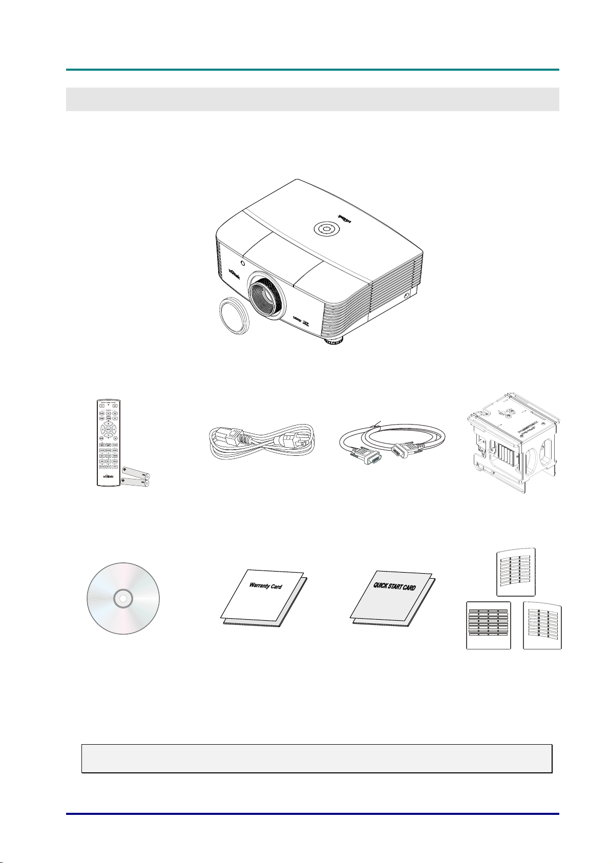
Carefully unpack the projector and check that the following items are included:
PROJECTOR WITH LENS CAP
EMOTE CONTROL
R
ITH TWO AA BATTERIES)
(W
CD-ROM
HIS USER’S MANUAL)
(T
P
OWER CORD VGA CABLE (1.8M)
W
ARRANTY CARD QUICK START CARD DUST FILTER
T
ILT LAMP MODULE
(O
(O
Contact your dealer immediately if any items are missing, appear damaged, or if the unit does not
work. It is recommend that you keep the original packing material should you ever need to return
the equipment for warranty service.
Caution:
Avoid using the projector in dusty environments.
PTIONAL)
PTIONAL)
— 1 —
Page 11
DLP Projector—User’s Manual
3
67810
9
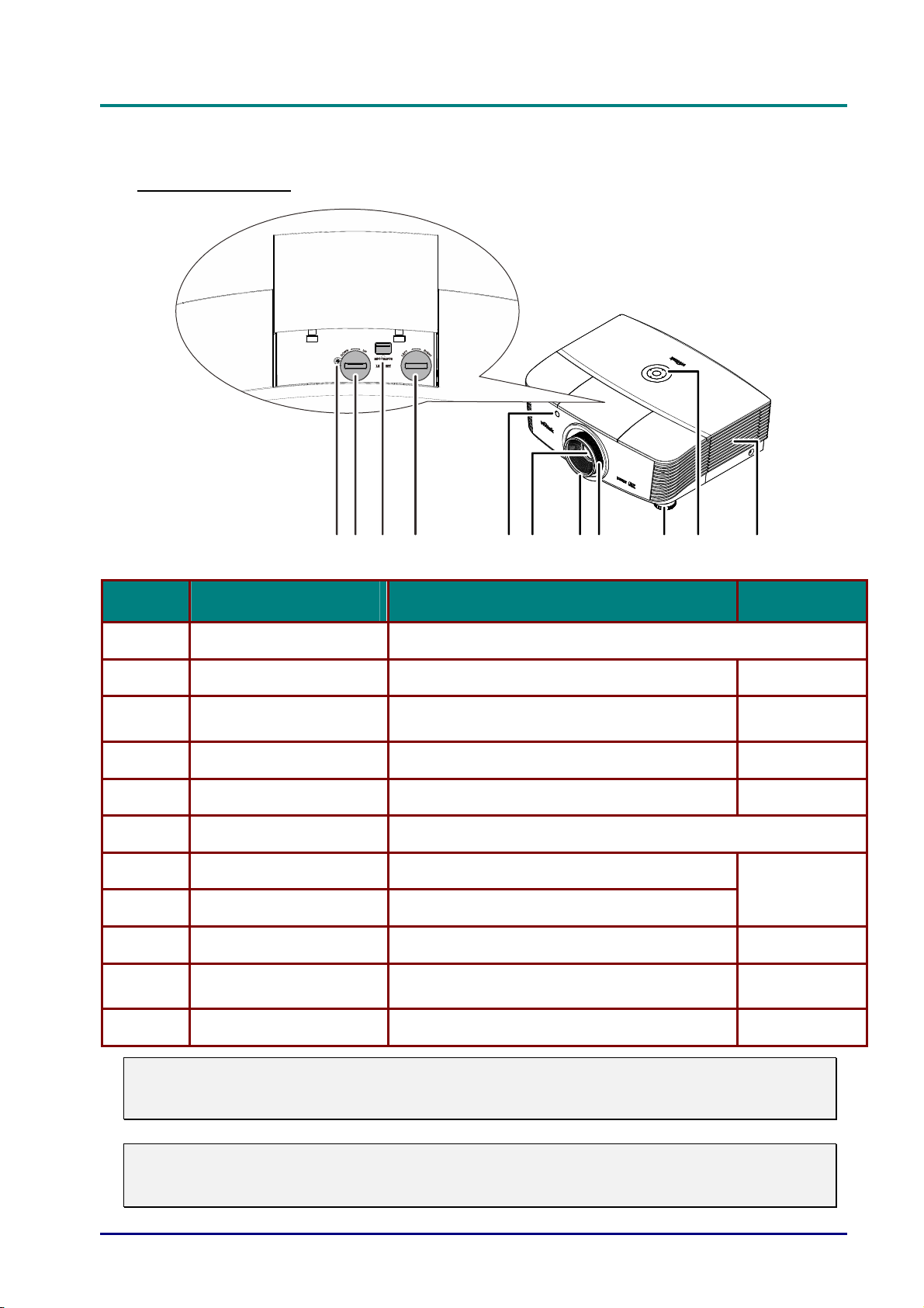
Views of Projector Parts
Front-right View
2
4
5
111
ITEM LABEL DESCRIPTION SEE PAGE:
1.
2.
3.
4.
5.
6.
7.
Screw For ensure the lens position
Vertical lens shift Adjusts the image position vertically
Lens release button
Horizontal lens shift Adjusts the image position horizontally
IR receiver Receives IR signal from remote control
Lens Projection Lens
Focus ring Focuses the projected image
Press the release button before removing the
lens
18
11
20
7
22
8.
9.
10.
Zoom ring Enlarges the projected image
Height adjuster Adjusts level of projector
Function keys
See Top view—On-screen Display (OSD)
buttons and LEDs.
17
3
11.
Important:
Ventilation openings on the projector allow for good air circulation, which keeps the projector
lamp cool. Do not obstruct any of the ventilation openings.
Note:
Suggest to loosen the screw before lens shift adjustment and tighten up after finished
adjustment.
Lamp cover Removes cover to replace lamp module
— 2 —
52
Page 12
D
L
P
P
r
o
D
L
D
L
j
P
P
r
o
j
P
P
r
o
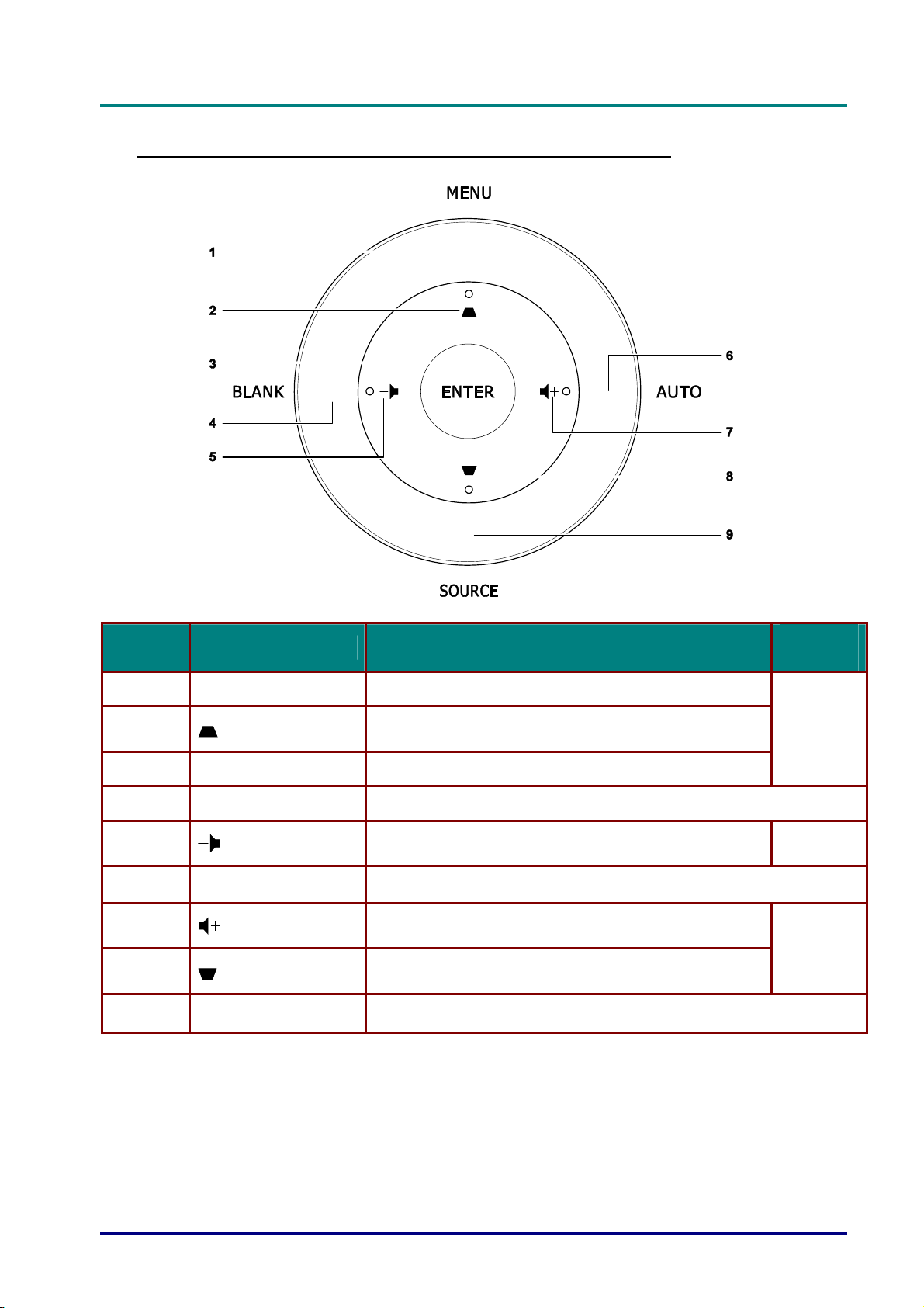
Top view—On-screen Display (OSD) buttons and LEDs
e
c
t
o
r
—
U
s
e
r
’
s
M
a
n
u
a
l
e
c
t
o
r
—
U
s
e
r
’
s
j
e
c
t
o
r
—
U
M
s
e
r
’
s
M
a
n
u
a
l
a
n
u
a
l
ITEM LABEL DESCRIPTION
1.
2.
3.
4.
5.
6.
7.
8.
9.
MENU Opens and exits OSD menus
ENTER Enter or confirm highlighted OSD menu item
BLANK Displays a blank screen and mutes audio
AUTO Optimizes image size, position, and resolution
SOURCE Enter the Source menu
Navigates and changes settings in the OSD
Quick Menu – For Keystone
Navigates and changes settings in the OSD
Quick Menu – For Volume -
Navigates and changes settings in the OSD
Quick Menu – For Volume +
Navigates and changes settings in the OSD
Quick Menu – For Keystone
SEE
PAGE:
24
24
24
– 3 –
Page 13
DLP Projector—User’s Manual
1617
3
5
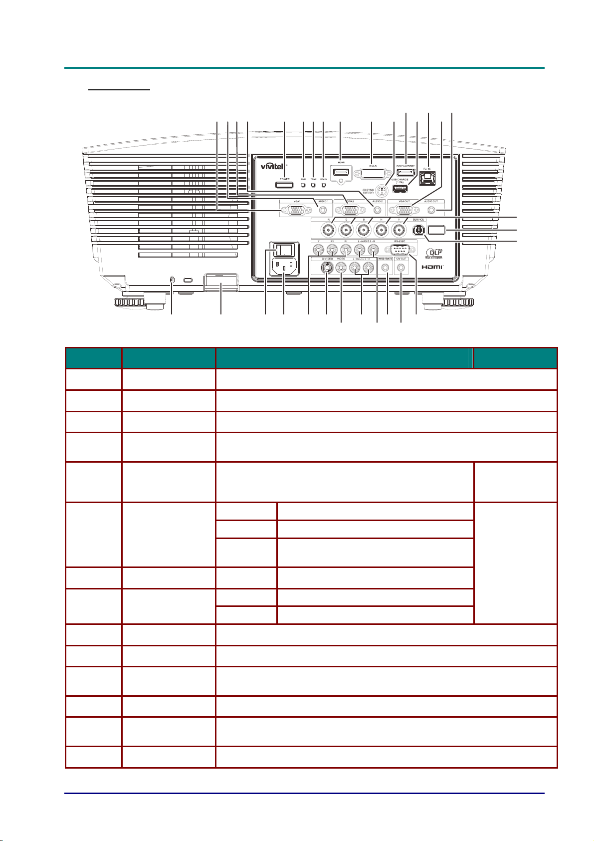
Rear view
12
4
3
56789
262728293031
2
10 1112131415
24
2
22
20
21
18
19
ITEM LABEL DESCRIPTION SEE PAGE:
1.
2.
VGA1 Connect a RGB cable from a computer or a video enabled device.
AUDIO IN 1 Connect the AUDIO cable from an input device.
3.
4.
5.
6.
7.
8.
9.
10.
11.
12.
VGA2 Connect a RGB cable from a computer or a video enabled device.
AUDIO IN 2
POWER
PWR LED
TEMP LED Red Over temperature
READY LED
HDMI Connect the HDMI cable from a HDMI device.
DVI-D Connect the DVI cable from a computer.
3D SYNC OUT
(5V)
DISPLAYPORT Connect a DISPLAYPORT cable to a DISPLAYPORT source.
Connect the AUDIO cable from an input device.
Note: Share with DVI & BNC audio input.
Turns the projector on or off (main power switch must
be turned on first). Press to place the projector in
standby mode.
Red Standby, Over Temperature
Blue Lamp Lit , System stable
Flashing
Red Lamp Lit , System stable, Lamp Fail
Flashing Error code (See as LED indicator table)
Connect 3D IR glasses receiver unit.
Power on, Cooling, Error code (See as
LED indicator table)
13
63
13.
14.
USB CHARGE
(1.5A)
RJ-45 Connect a LAN cable from Ethernet.
For USB charge.
— 4 —
Page 14
D
L
P
P
r
o
j
e
c
t
o
r
—
U
s
e
r
’
s
M
a
n
u
D
D
L
P
P
r
o
j
e
c
t
o
r
—
U
s
e
r
’
s
L
P
P
r
o
j
e
c
t
o
r
—
U
s
e
r
’
s
M
M
a
a
n
u
a
a
n
u
a
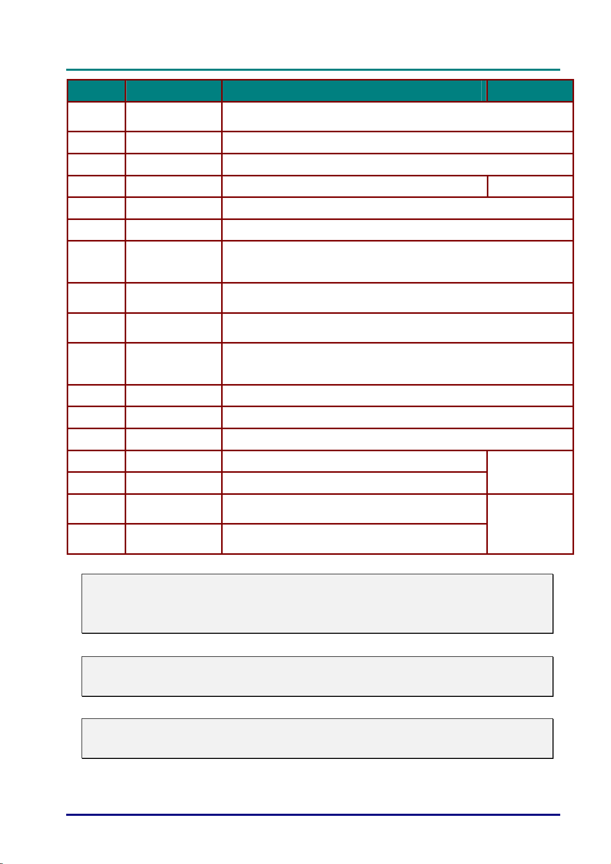
ITEM LABEL DESCRIPTION SEE PAGE:
l
l
l
15.
16.
17.
18.
19.
20.
21.
22.
23.
24.
25.
VGA OUT
AUDIO OUT Connect an AUDIO cable for audio loop through.
BNC Connect a BNC cable from a computer.
IR receiver Receive IR signal from remote control.
SERVICE For service use.
RS-232 Connects RS-232 serial port cable for remote control.
12V
WIRED REMOTE
AUDIO IN 3 L/R
RCA (YPbPr)
AUDIO IN 4 L/R
RCA (Video/ SVideo)
VIDEO Connect the composite cable from a video device.
Connect the RGB cable to a display.
(Pass through by VGA1 only)
When connected to the screen through a commercially available cable,
the screen deploys automatically on start up of the projector. The screen
retracts when the projector is powered off (see notes below).
Wire remote control connector (connect with wire remote connector of the
Remote Control set).
Connect the audio cables from a audio device.
Connect the audio cables from a audio device.
7
26.
27.
28.
29.
30.
31.
Note:
y
To use this feature, you must plug in the connector before turn on/off the projector.
y
Screen controllers are supplied and supported by screen manufacturers.
y
Do not use this jack for anything other than intended use.
Note:
If your video equipment has both S-VIDEO and RCA jacks (composite video) connect to the
S-VIDEO connector. S-VIDEO provides a better quality signal.
S-VIDEO Connect the S-video cable from a video device.
YPbPr Connect a component video enabled device.
AC IN Connects the power cable.
Power switch Turns on/off the projector.
Security chain
lock
Kensington Lock
Helps protect the projector from unauthorized use.
Secures to permanent object with a Kensington® Lock
system.
13
61
Warning:
As a safety precaution, disconnect all power to the projector and connecting devices before
making connections.
– 5 –
Page 15
DLP Projector—User’s Manual
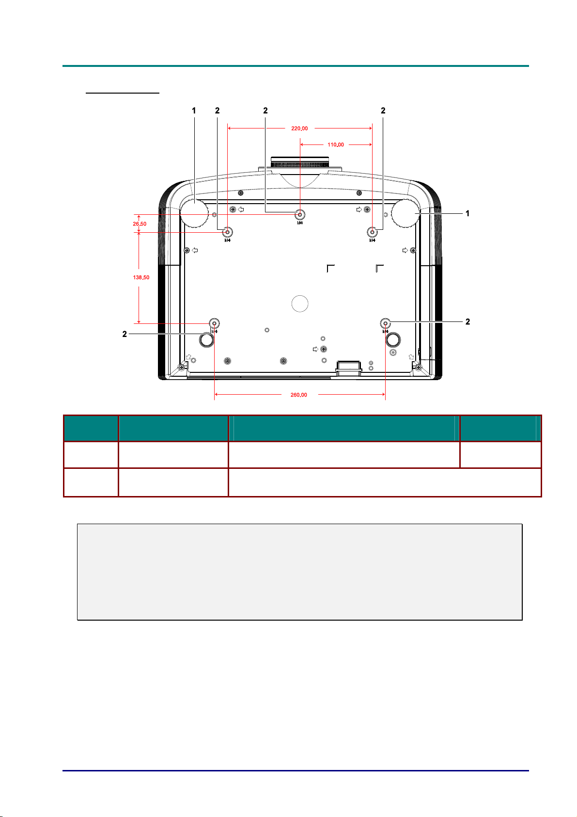
Bottom view
ITEM LABEL DESCRIPTION SEE PAGE:
1.
2.
Note:
When installing, ensure that you use only UL Listed ceiling mounts.
For ceiling installations, use approved mounting hardware and M4 screws with a maximum
screw depth of 6 mm (0.23 inch).
The construction of the ceiling mount must be of a suitable shape and strength. The ceiling
mount load capacity must exceed the weight of the installed equipment, and as an additional
precaution be capable of withstanding three times the weight of the equipment (not less than
5.15 kg) over a period of 60 seconds.
Tilt adjustor Rotate adjuster lever to adjust angle position.
Ceiling support holes
Contact your dealer for information on mounting the projector on a
ceiling
17
— 6 —
Page 16
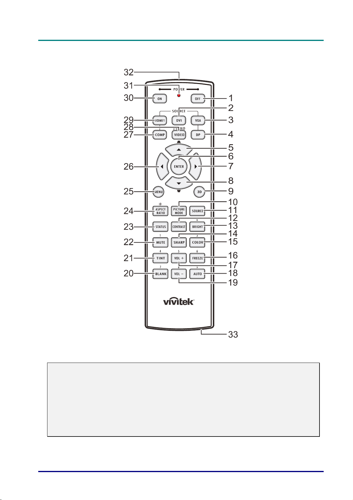
Remote Control Parts
D
D
D
L
P
P
r
o
j
e
c
t
o
r
—
U
s
e
r
’
s
M
a
n
u
a
l
L
P
P
r
o
j
e
c
t
o
r
—
U
s
e
r
’
s
L
P
P
r
o
j
e
c
t
o
r
—
U
M
s
e
r
’
s
M
a
n
u
a
l
a
n
u
a
l
Important:
1. Avoid using the projector with bright fluorescent lighting turned on. Certain high-frequency
fluorescent lights can disrupt remote control operation.
2. Be sure nothing obstructs the path between the remote control and the projector. If the path
between the remote control and the projector is obstructed, you can bounce the signal off
certain reflective surfaces such as projector screens.
3. The buttons and keys on the projector have the same functions as the corresponding buttons
on the remote control. This user’s manual describes the functions based on the remote control.
– 7 –
Page 17

DLP Projector—User’s Manual
ITEM LABEL DESCRIPTION SEE PAGE:
1.
2.
Power OFF Turns the projector off
DVI Displays the DVI source selection
13
3.
4.
5.
6.
7.
8.
9.
10.
11.
12.
13.
14.
15.
16.
17.
VGA Displays the VGA source selection
DP Displays the DisplayPort source selection
Up cursor /
Keystone+
ENTER Enters and confirms settings in the OSD
Right cursor Navigates and changes settings in the OSD
Down cursor /
Keystone-
3D Activate 3D video (not available in D5180HD series)
PICTURE MODE Changes the Display Mode setting
SOURCE Alternate input source
CONTRAST Displays the contrast settings bar
BRIGHT Displays the brightness setting bar
SHARP Displays the sharpness setting bar
COLOR Displays the color setting bar
FREEZE Freezes/unfreezes the on-screen picture
VOL + Adjusts volume
Navigates and changes settings in the OSD
Quick Menu – For Keystone
Navigates and changes settings in the OSD
Quick Menu – For Keystone
24
24
18.
19.
20.
21.
22.
23.
24.
25.
26.
27.
28.
29.
30.
31.
32.
33.
AUTO Auto adjustment for frequency, phase, and position
VOL - Adjusts volume
BLANK Makes the screen blank
TINT Displays the tint setting bar
MUTE Mutes the built-in speaker
STATUS
ASPECT RATIO Displays the ASPECT RATIO selections
MENU
Left cursor Navigates and changes settings in the OSD
COMP Displays the Component source selection
VIDEO Displays the VIDEO source selection
HDMI 1 Displays the HDMI 1 source selection
Power ON Turns the projector on
Status LED Lights when the remote control is used
IR transmitter Transmits signals to projector
Wired remote
connector
Opens the OSD Status menu (the menu only opens when an input
device is detected)
Opens
Wired remote function
or closed the OSD
used
24
24
24
13
— 8 —
Page 18

D
L
P
P
r
o
j
e
c
t
o
r
—
U
s
e
r
’
D
D
L
P
P
r
o
j
e
c
t
o
r
L
P
P
r
o
—
j
e
c
t
o
r
—
U
U
s
s
e
r
’
s
e
r
’
Remote Control Operating Range
The remote control uses infrared transmission to control the projector. It is not necessary to point
the remote directly at the projector. Provided you are not holding the remote perpendicular to the
sides or the rear of the projector, the remote will function well within a radius of about 7 meters (23
feet) and 15 degrees above or below the projector level. If the projector does not respond to the
remote control, move a little closer.
Projector and Remote Control Buttons
The projector can be operated using the remote control or the buttons on the top of the projector.
All operations can be carried out with the remote control; however, the buttons on the projector
are limited in use.
M
a
n
u
a
l
s
M
s
M
a
n
u
a
l
a
n
u
a
l
– 9 –
Page 19
DLP Projector—User’s Manual
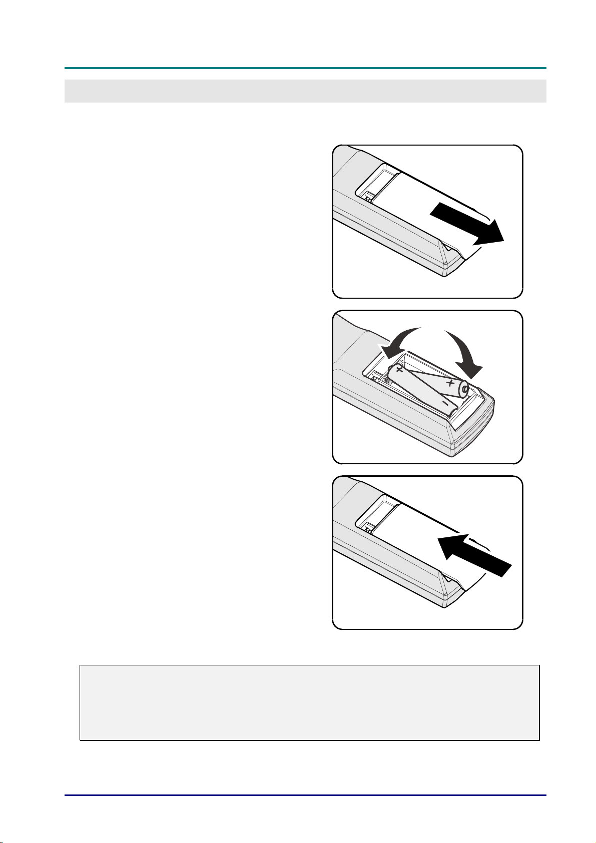
Inserting the Remote Control Batteries
Remove the battery compartment
1.
cover by sliding the cover in the
direction of the arrow.
Insert the battery with the positive
2.
side facing up.
SETUP AND OPERATION
Replace the cover.
3.
Caution:
1. Only use AA batteries (Alkaline batteries are recommended).
2. Dispose of used batteries according to local ordinance regulations.
3. Remove the batteries when not using the projector for prolonged periods.
— 10 —
Page 20
D
L
P
P
r
o
j
e
c
t
o
r
—
D
D
L
P
P
r
o
j
e
L
P
c
P
r
o
j
e
c
U
t
o
r
—
U
t
o
r
—
U
Installing or Removing the Optional Lens
Caution:
y
Do not shake or place excessive pressure on the projector or the lens components as the
projector and lens components contain precision parts.
y
Before removing or installing the lens, be sure to turn off the projector, wait until the cooling
fans stop, and turn off the main power switch.
y
Do not touch the lens surface when removing or installing the lens.
y
Keep fingerprints, dust or oil off the lens surface.
y
Do not scratch the lens surface.
y
Work on a level surface with a soft cloth under it to avoid scratching.
y
If you remove and store the lens, attach the lens cap to the projector to keep off dust and dirt.
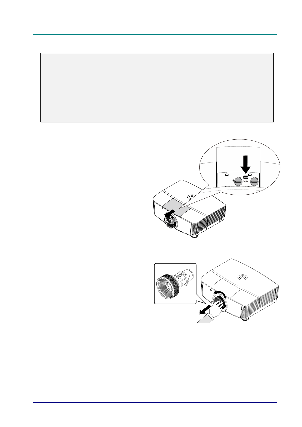
Removing the Existing Lens From the Projector
Pull and release the top cover to
1.
open as shown.
s
e
r
’
s
M
a
n
u
a
l
s
e
r
’
s
M
s
e
r
’
s
M
a
n
u
a
l
a
n
u
a
l
Push the LENSE RELEASE button
2.
to the unlock position.
Grasp the lens.
3.
Rotate the lens counterclockwise.
4.
The existing lens will be
disengaged.
Pull out the existing lens slowly.
5.
– 11 –
Page 21
DLP Projector—User’s Manual
El
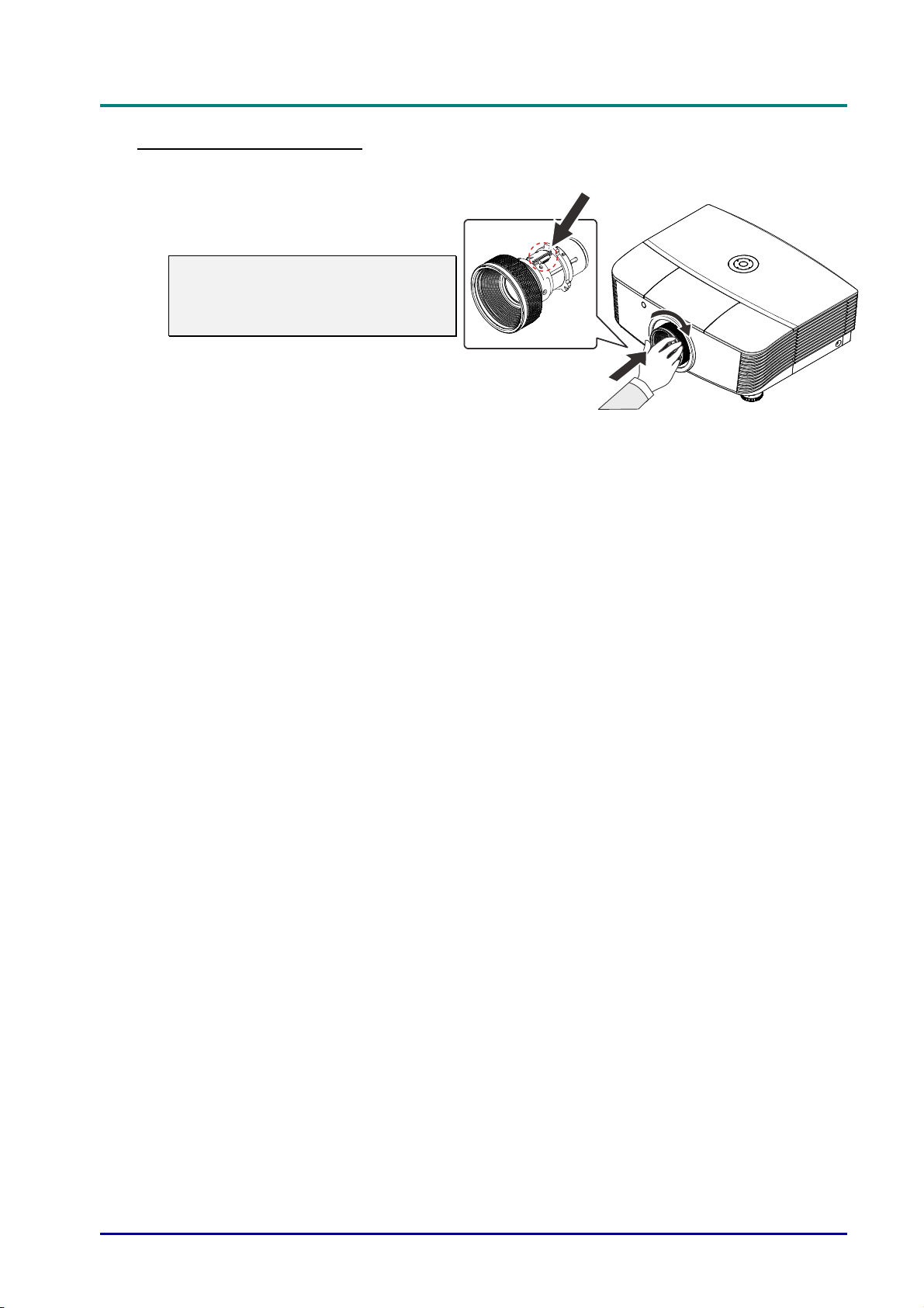
Installing the New Lens
Align the notches and correctly
1.
position the electrical contact pad as
shown in the picture.
Note:
Pin of Electrical contact pins should
be in the direction as shown in the
picture.
Rotate the lens clockwise until you
2.
feel it click into place.
ectrical contact pins
— 12 —
Page 22
Starting and Shutting down the Projector
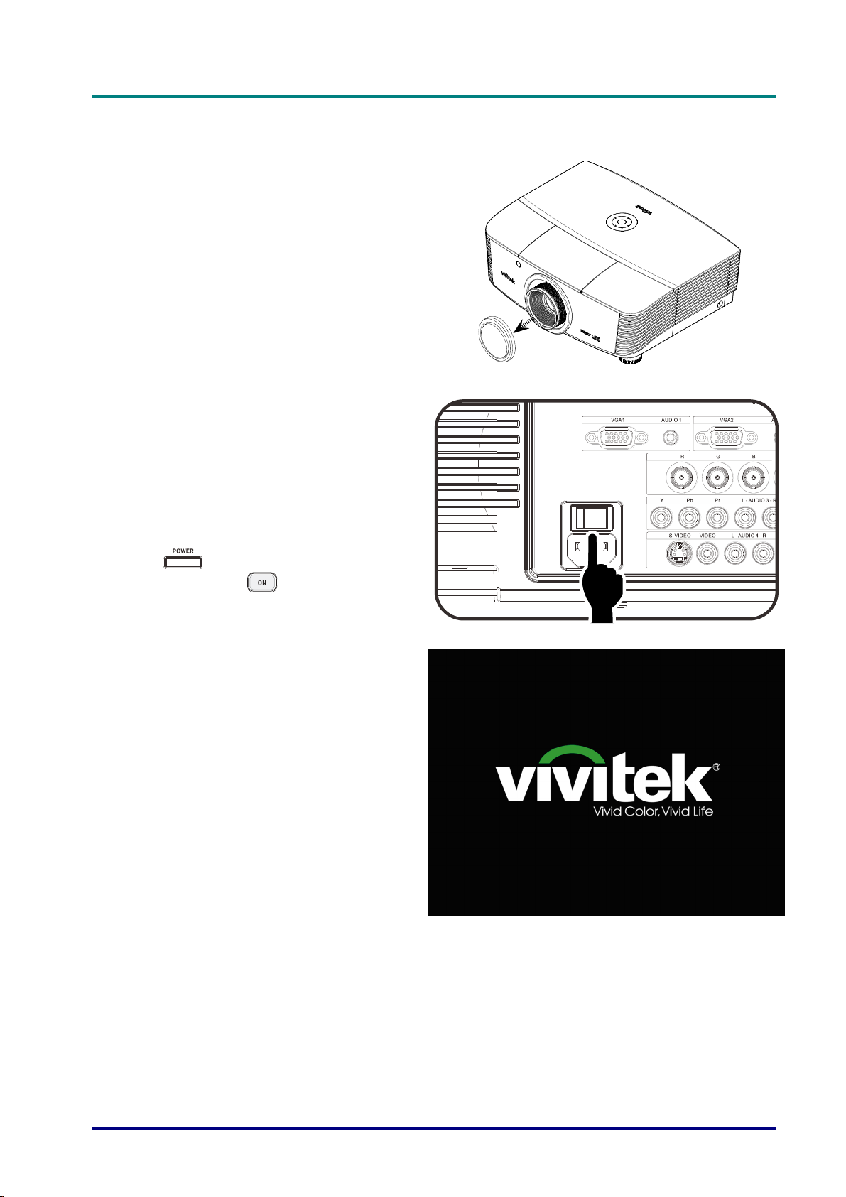
Remove the lens cap.
1.
Securely connect the power cord
2.
and signal cable. When connected,
the power led will turn red.
D
D
D
L
P
P
r
o
j
e
c
t
o
r
—
U
s
e
r
’
s
M
a
n
u
a
l
L
P
P
r
o
j
e
c
t
o
r
—
U
s
e
r
’
s
L
P
P
r
o
j
e
c
t
o
r
—
U
M
s
e
r
’
s
M
a
n
u
a
l
a
n
u
a
l
Turn on the lamp by pressing
3.
“
projector or “
control.
The PWR LED will now flash red.
The startup screen will display in
approximately 30 seconds. The first
time you use the projector, you can
select your preferred language from
quick menu after the startup screen
display.
” button on the rear of the
” on the remote
– 13 –
Page 23
DLP Projector—User’s Manual
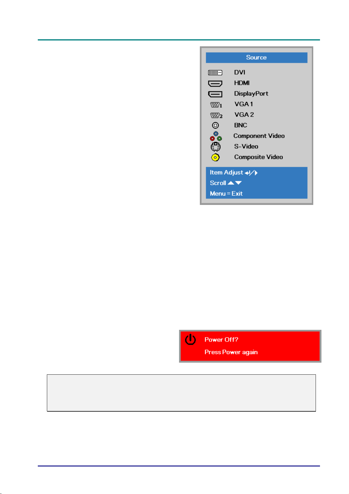
If more than one input device is
4.
connected, press the SOURCE
button and use ▲▼ to scroll among
devices.
• DVI: Digital Visual Interface
• HDMI: High-Definition Multimedia Interface
• DisplayPort: Digital display interface
• VGA 1 / 2: Analog RGB 1 / 2
• BNC: Analog RGB (BNC connector)
•
Component Video: DVD input YCbCr / YPbPr , or
• S-Video: Super video (Y/C separated)
• Composite Video: Traditional composite video
When the “Power Off? /Press
5.
Power again” message appears,
press the POWER button. The
projector turns off.
Caution:
1. Be sure to remove the lens cap before starting projector.
compatible
HDTV input YPbPr
2. Do not unplug the power cord until the READY LED stops flashing–indicating the projector
has cooled down.
— 14 —
Page 24
D
L
P
P
r
o
j
e
c
t
o
r
—
U
s
D
D
L
P
P
r
o
j
e
c
t
o
L
P
P
r
o
r
j
e
c
t
o
r
—
—
U
U
e
s
s
Setting an Access Password (Security Lock)
You can use the four (arrow) buttons to set a password and prevent unauthorized use of the
projector. When enabled, the password must be entered after you power on the projector. (See
Navigating the OSD on page 24 and Setting the OSD Language on page 25 for help on using
OSD menus.)
Important:
Keep the password in a safe place. Without the password, you will not be able to use the
projector. If you lose the password, contact your reseller for information on clearing the
password.
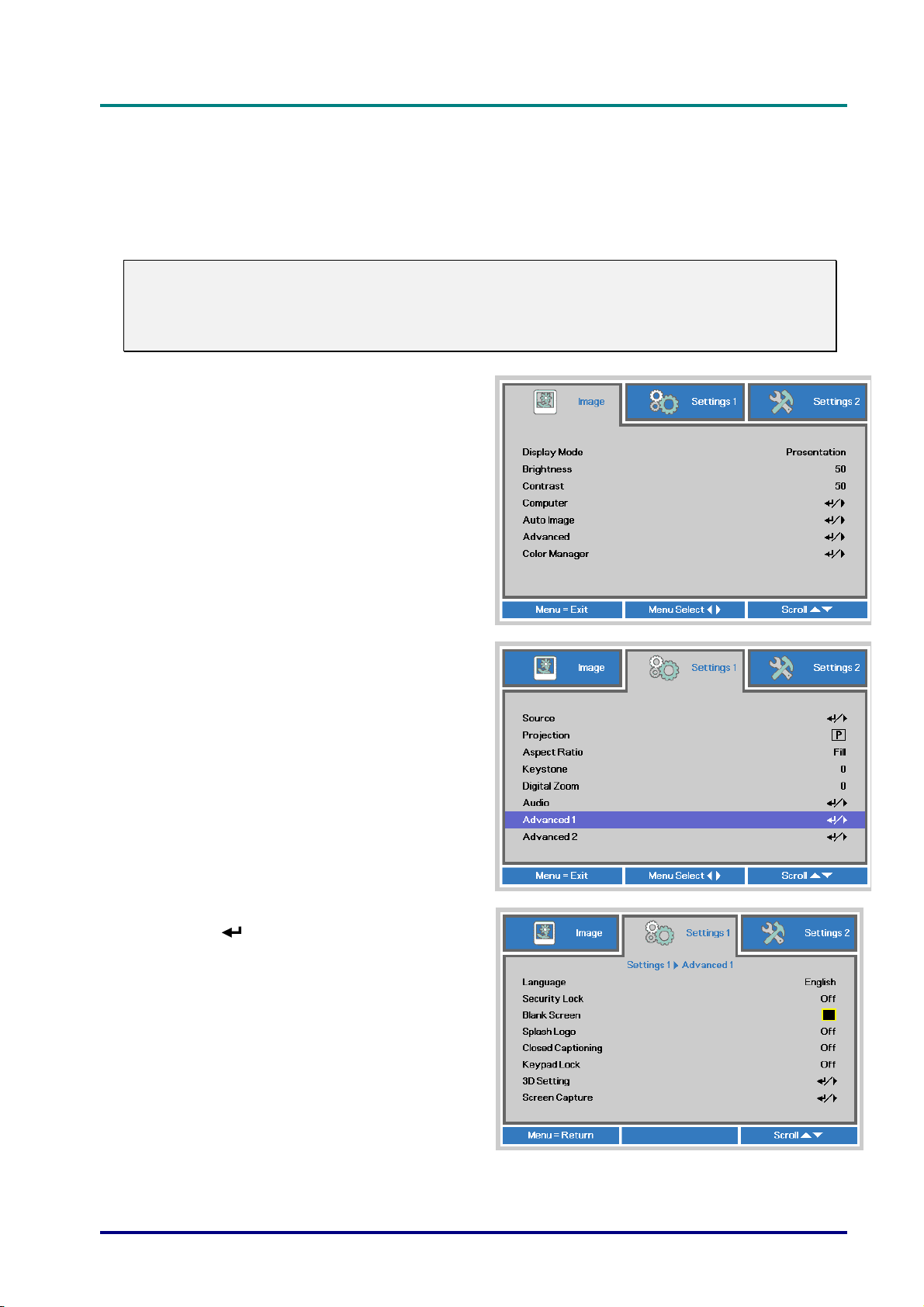
Press the MENU button to open the
1.
OSD menu.
r
’
s
M
a
n
u
a
l
e
r
’
s
M
e
r
’
s
M
a
n
u
a
l
a
n
u
a
l
Press the cursor ◄► button to move to
2.
the Settings 1 menu, press the cursor
▲▼ button to select Advanced 1.
Press (Enter) / ► to enter the
3.
Advanced 1 sub menu. Press the
cursor ▲▼ button to select Security
Lock.
Press the cursor ◄► button to enter
4.
and enable or disable security lock
function.
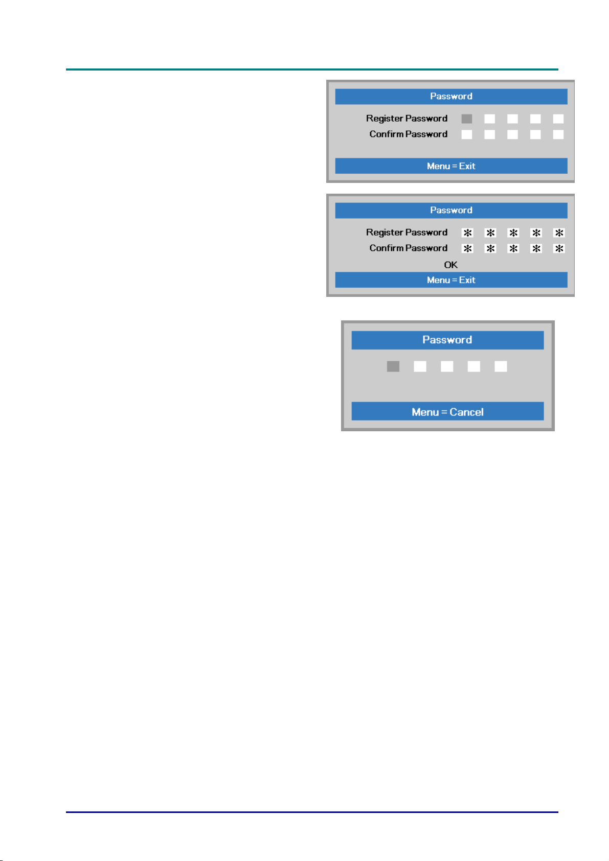
A password dialog box automatically
appears.
– 15 –
Page 25
DLP Projector—User’s Manual
You can use the cursor buttons
5.
▲▼◄►
either on keypad or IR remote control
for password entry. You can use any
combination including the same arrow
five times, but not less than five.
Press the cursor buttons in any order to
set the password. Push the MENU
button to exit the dialog box.
The password confirm menu appears
6.
when user presses the power-on key in
case the Security Lock is enabled.
Enter the password in the order you set
it at step 5. In case you forget the
password, please contact the service
center.
The service center will validate the
owner and help reset the password.
— 16 —
Page 26
Adjusting the Projector Level
Take note of the following when setting up the projector:
• The projector table or stand should be level and sturdy.
• Position the projector so that it is perpendicular to the screen.
• Remove the Back Foot Holder on the rear adjuster foot before adjusting the projection
angle.
• Ensure the cables are in a safe location. You could trip over them.
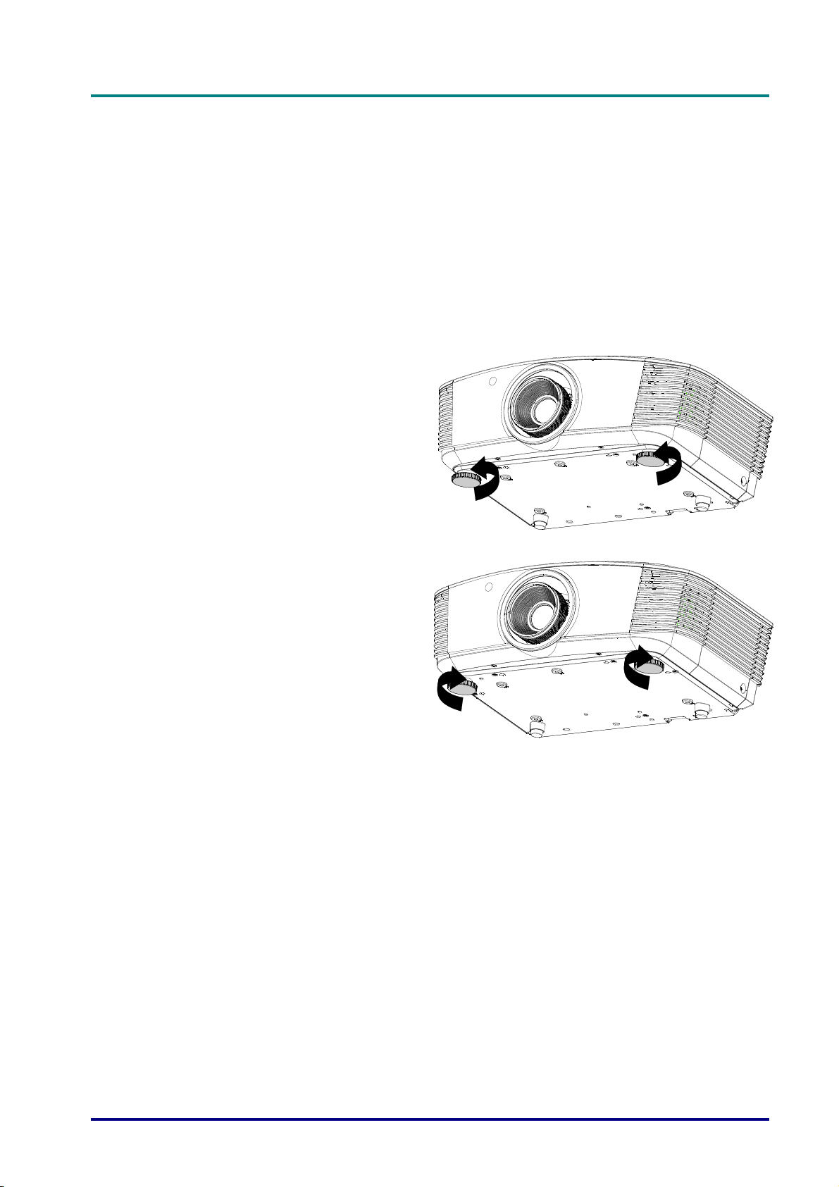
To raise the level of the projector,
1.
twist the adjusters counter
clockwise.
D
L
P
P
r
o
j
e
c
t
o
r
—
U
s
e
r
’
s
M
a
n
u
a
l
D
L
P
P
r
o
j
e
c
t
o
r
—
U
s
e
r
’
s
D
L
P
P
r
o
j
e
c
t
o
r
—
U
M
s
e
r
’
s
M
a
n
u
a
l
a
n
u
a
l
To lower the level of the projector,
2.
lift the projector and twist the
adjusters clockwise.
– 17 –
Page 27
DLP Projector—User’s Manual
S
UXGA /
Adjusting Projected Image Position Using Shift
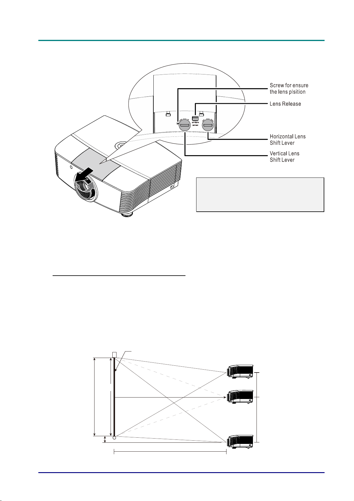
Note:
Suggest to loosen the screw before lens
shift adjustment and tighten up after
finished adjustment.
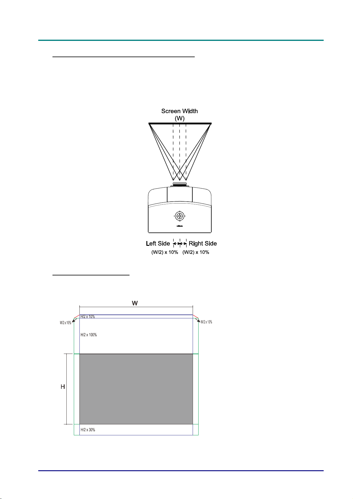
The Shift feature provides a lens shift function that can be used to adjust the position of the
projected image either horizontally or vertically within the range detailed below.
Shift is a unique system that provides lens shift while maintaining a much higher ANSI contrast
ratio than traditional lens shift systems.
Adjusting the vertical image position
The vertical image height can be adjusted between 110% and -30% ( WUXGA, WXGA), 100%
and -20% (XGA), 120% and -40% ( 1080P) of offset position. Note that the maximum vertical
image height adjustment can be limited by the horizontal image position. For example it is not
possible to achieve the maximum vertical image position height detailed above if the horizontal
image position is at maximum. Please consult the Shift Range diagram below for further
clarification.
WUXGA and WXGA
creen
-30%
100%
(H)
30% x (H/2)
0%
Screen Height
(H/2) x 10%
W
Distance
(L)
WXGA
— 18 —
110% x (H/2)
+110%
Page 28
XGA
H
GA
)
S
080
)
1080P
D
L
P
P
r
o
j
e
c
t
o
r
—
U
s
e
r
’
s
M
a
n
u
a
l
D
L
P
P
r
o
j
e
c
t
o
r
—
U
s
e
r
’
s
D
L
P
P
r
o
j
e
c
t
o
r
—
U
Screen
-20%
100%
eight
(H)
Screen
100% x (H/2
+100%
Distance
(L)
X
M
s
e
r
’
s
M
a
n
u
a
l
a
n
u
a
l
Screen Height
(H/2) x 20%
100%
(H)
creen
Distance
(L)
P
1
-40%
40% x (H/2)
0%
120% x (H/2
+120%
– 19 –
Page 29
DLP Projector—User’s Manual
Adjusting the horizontal image position
With the lens in the center position the horizontal image position can be adjusted to the left or right
by up to a maximum of 10% of the half image width. Note that the maximum horizontal image
height adjustment can be limited by the vertical image position. For example it is not possible to
achieve the maximum horizontal image position if the vertical image position is at maximum.
Please consult the Shift Range diagram below for further clarification.
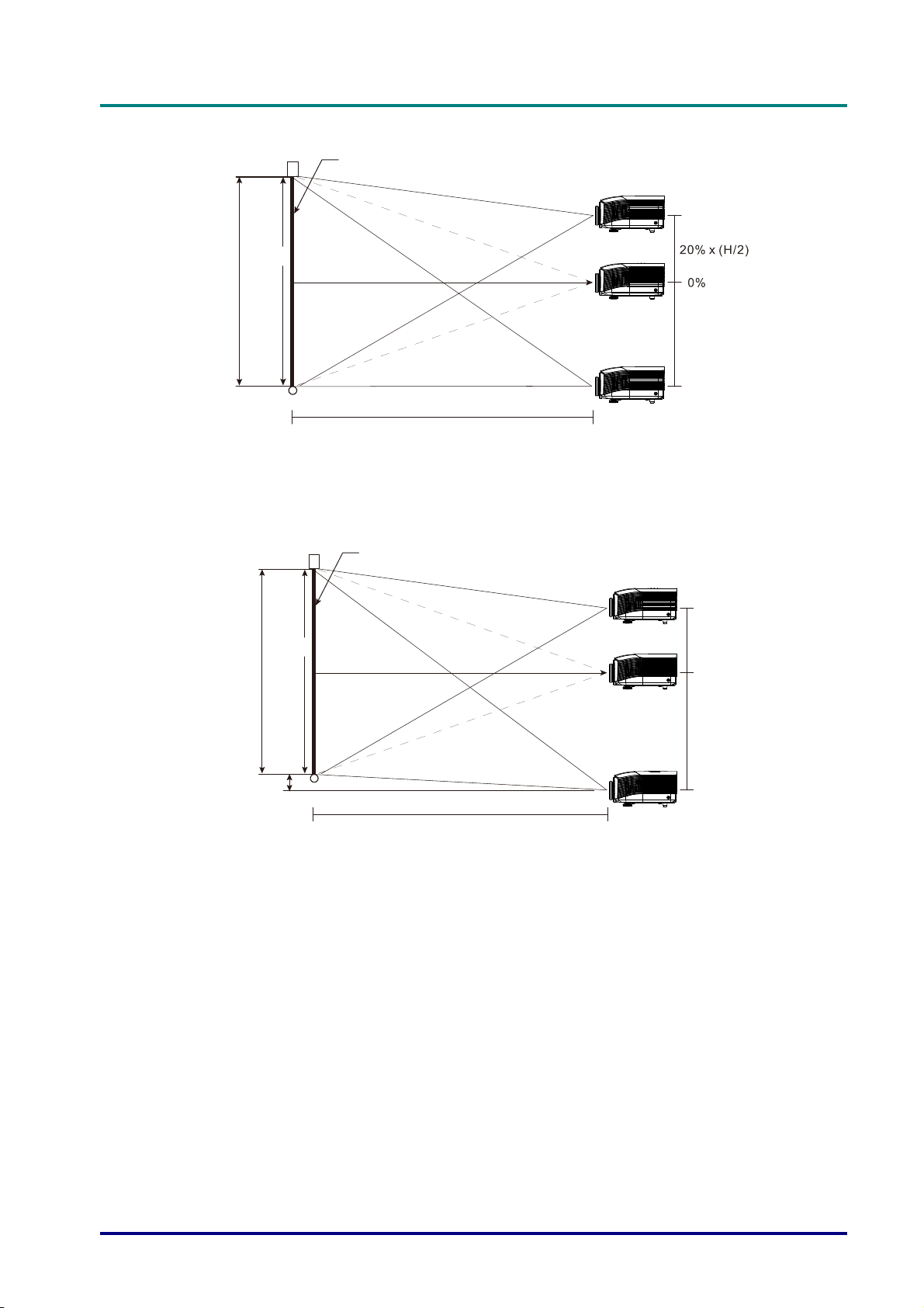
Shift Range Diagram
WUXGA and WXGA
The max H up shift = H/2 x 110%
The max H down shift = H/2 x 30%
The max W shift = W/2 x 10%
When max W shift is W/2 x 10%
max H shift = H/2 x 100%
When max H shift is H/2 x 110%
max W shift = H x 0%
— 20 —
Page 30
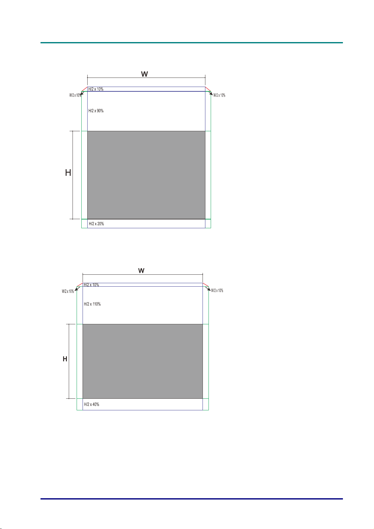
XGA
D
L
P
P
r
o
j
e
c
t
o
r
—
U
s
e
r
’
s
M
a
D
L
P
P
r
o
j
e
c
t
o
r
—
U
s
e
D
L
P
P
r
o
j
e
c
t
o
r
—
The max H up shift = H/2 x 100%
The max H down shift = H/2 x 20%
The max W shift = W/2 x 10%
When max W shift is W/2 x 10%
max H shift = H/2 x 90%
When max H shift is H/2 x 100%
max W shift = H x 0%
U
r
s
e
r
n
’
s
M
a
n
’
s
M
a
n
u
a
l
u
a
l
u
a
l
1080P
The max H up shift = H/2 x 120%
The max H down shift = H/2 x 20%
The max W shift = W/2 x 10%
When max W shift is W/2 x 10%
max H shift = H/2 x 110%
When max H shift is H/2 x 120%
max W shift = H x 0%
– 21 –
Page 31
DLP Projector—User’s Manual
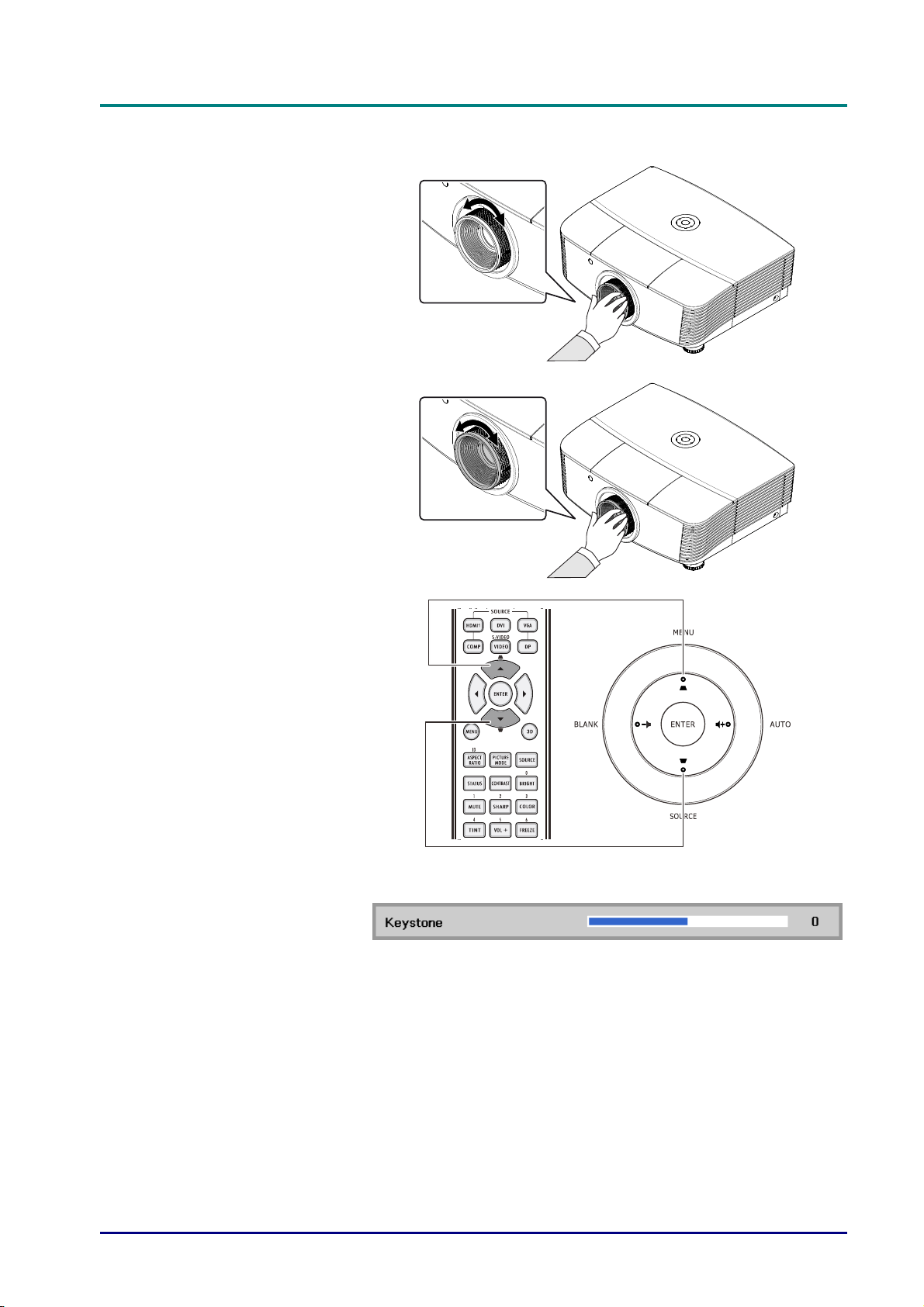
Adjusting the Zoom, Focus and Keystone
Use the Image-zoom
1.
control (on the projector
only) to resize the
projected image and
screen size.
Use the Image-focus
2.
control (on the projector
only) to sharpen the
projected image.
Use the KEYSTONE
3.
buttons (on the
projector or the remote
control) to correct
image-trapezoid (wider
top or bottom)
effect.
The keystone control
4.
appears on the display.
Remote control and OSD panel
— 22 —
Page 32
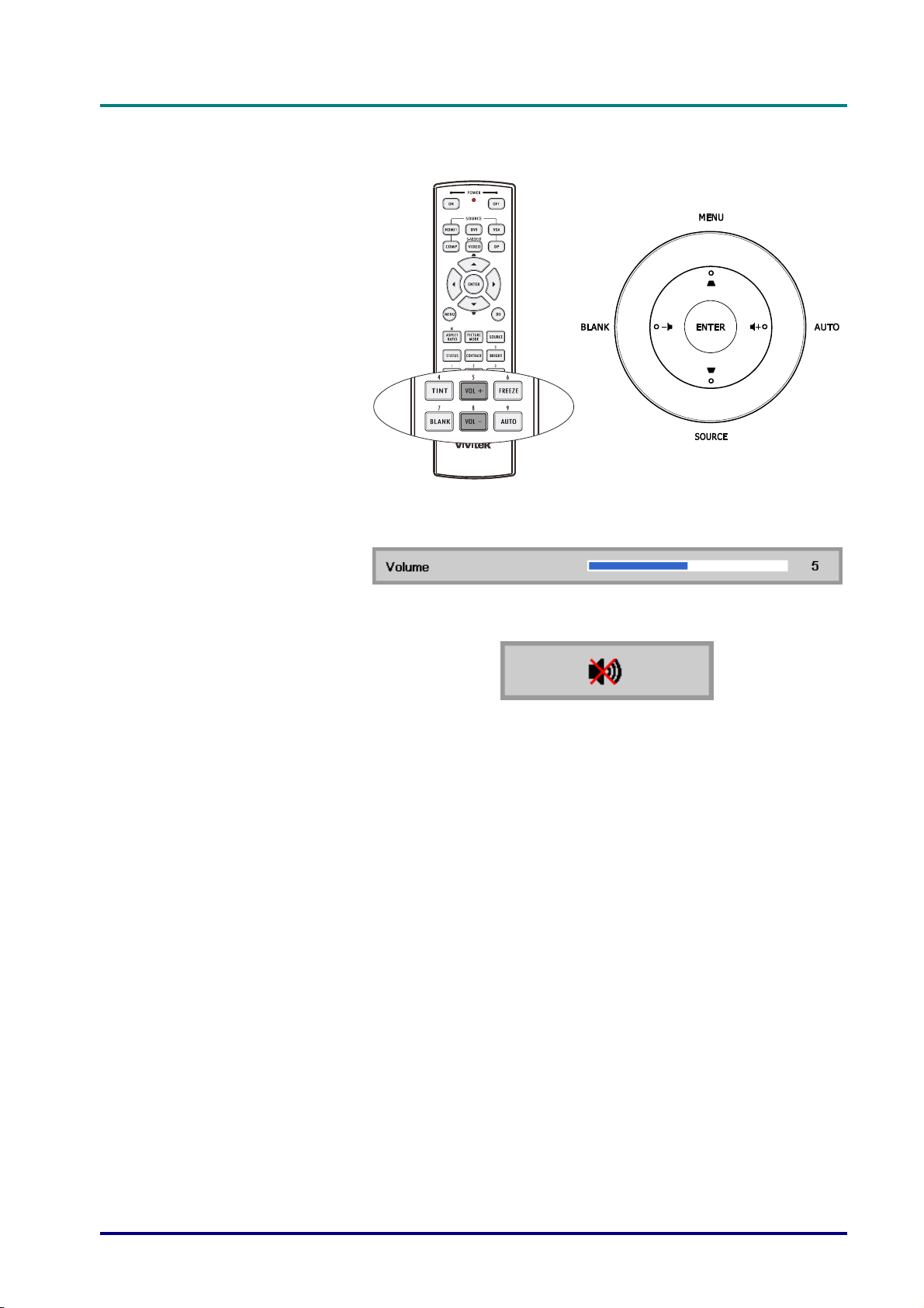
Adjusting the Volume
Press the Volume +/-
1.
buttons on the remote
control.
The volume control
appears on the display.
Press the Left or Right
2.
Cursor buttons on the
keypad to adjust
Volume +/-.
D
D
D
L
P
P
r
o
j
e
c
t
o
r
—
U
s
e
r
’
s
M
a
n
u
a
l
L
P
P
r
o
j
e
c
t
o
r
—
U
s
e
r
’
s
L
P
P
r
o
j
e
c
t
o
r
—
U
M
s
e
r
’
s
M
a
n
u
a
l
a
n
u
a
l
Press the MUTE button
3.
to turn off the volume
(This feature is
available only on the
remote).
– 23 –
Page 33
DLP Projector—User’s Manual
6
ON-SCREEN DISPLAY (OSD) MENU SETTINGS
OSD Menu Controls
The projector has an OSD that lets you make image adjustments and change various settings.
Navigating the OSD
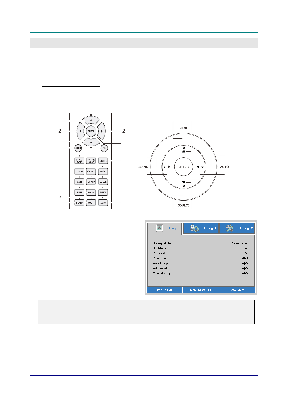
You can use the remote control cursor buttons or the buttons on the top of the projector to
navigate and make changes to the OSD. The following illustration shows the corresponding
buttons on the projector.
1
1
3
7
1. To enter the OSD, press the MENU
button.
2. There are three menus. Press the cursor
◄► button to move through the menus.
3. Press the cursor ▲▼ button to move up
and don in a menu.
5
6
4
13
7
2
1
4
2
5
4. Press ◄► to change values for settings.
5. Press MENU to close the OSD or leave
a submenu.
Note:
Depending on the video source, not all items in the OSD are available. For example, the
Horizontal/Vertical Position items in the Computer menu can only be modified when
connected to a PC. Items that are not available cannot be accessed and are grayed out.
— 24 —
Page 34
Setting the OSD Language
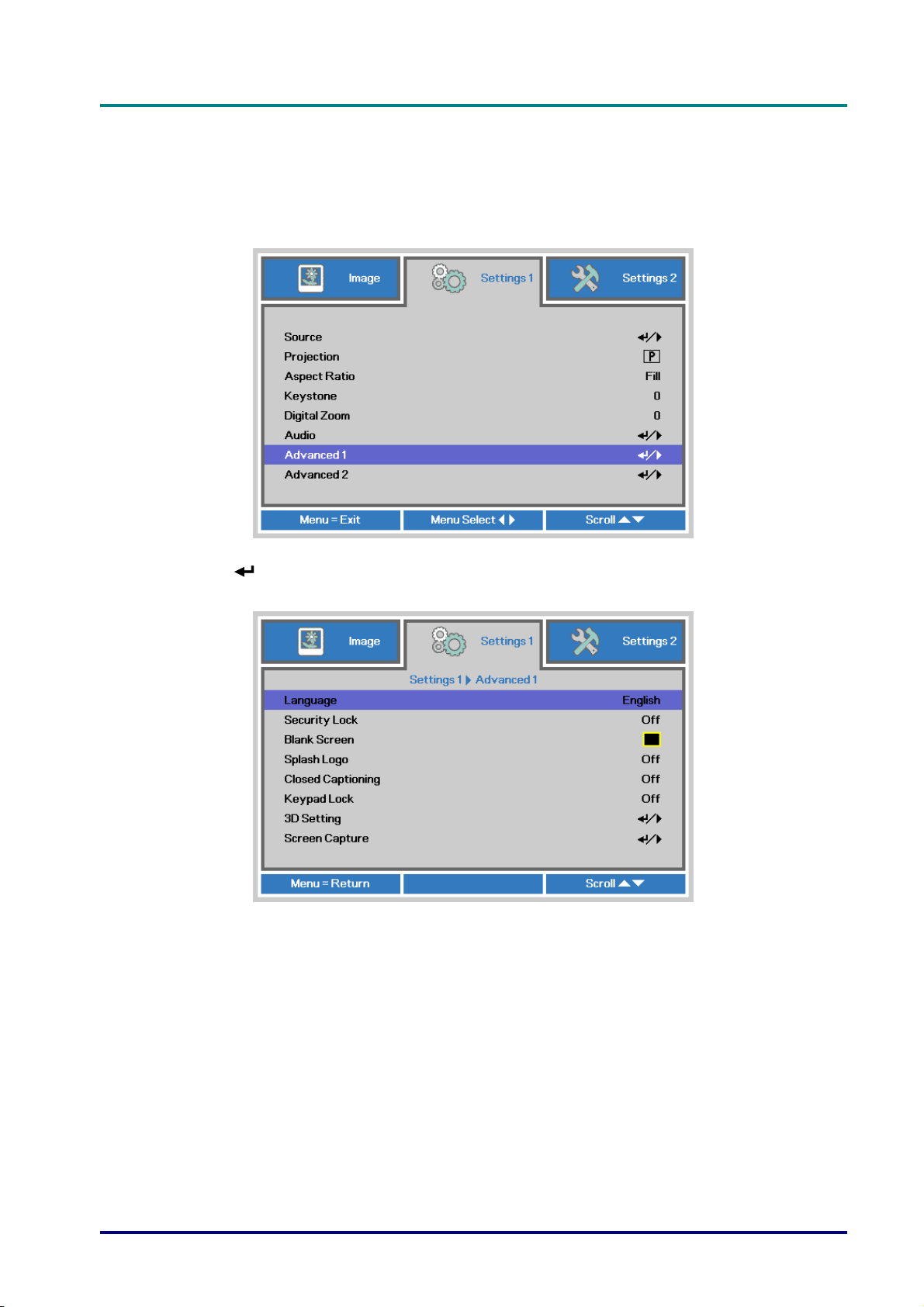
Set the OSD language to your preference before continuing.
1. Press the MENU button. Press the cursor ◄► button to navigate to Settings 1. Press
the cursor ▲▼ button to move to the Advanced 1 menu.
D
D
D
L
P
P
r
o
j
e
c
t
o
r
—
U
s
e
r
’
s
M
a
n
u
a
l
L
P
P
r
o
j
e
c
t
o
r
—
U
s
e
r
’
s
L
P
P
r
o
j
e
c
t
o
r
—
U
M
s
e
r
’
s
M
a
n
u
a
l
a
n
u
a
l
2. Press (Enter) / ► to enter the Advanced 1 sub menu. Press the cursor ▲▼ button
until Language is highlighted.
3. Press the cursor button until the language you want is highlighted.
4. Press the MENU button four times to close the OSD.
– 25 –
Page 35
DLP Projector—User’s Manual
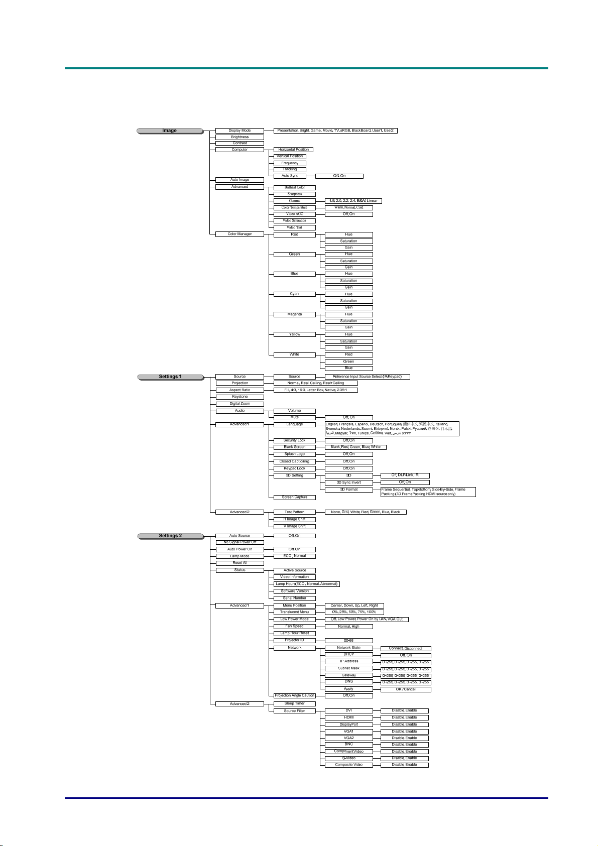
OSD Menu Overview
Use the following illustration to quickly find a setting or determine the range for a setting.
— 26 —
Page 36
D
L
P
P
r
o
j
e
c
t
o
r
—
U
s
e
D
D
L
P
P
r
o
j
e
c
t
o
r
L
P
P
r
o
—
j
e
c
t
o
r
—
U
U
r
s
e
r
s
e
r
Image Menu
Attention !
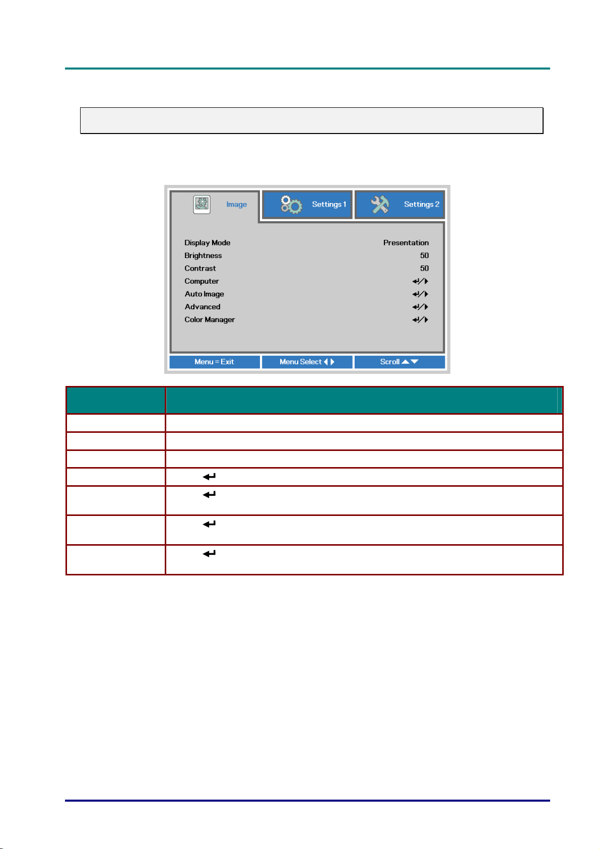
All of display mode parameters when changed will be saved to user mode.
Press the MENU button to open the OSD menu. Press the cursor ◄► button to move to the
Image Menu. Press the cursor ▲▼ button to move up and down in the Image menu. Press ◄►
to enter and change values for settings.
’
s
M
a
n
u
a
l
’
s
M
’
s
M
a
n
u
a
l
a
n
u
a
l
ITEM DESCRIPTION
Display Mode Press the cursor ◄► button to enter and set the Display Mode.
Brightness Press the cursor ◄► button to enter and adjust the display brightness.
Contrast Press the cursor ◄► button to enter and adjust the display contrast.
Computer Press (Enter) / ► to enter the Computer menu. See Computer Menu on page 28.
Auto Image
Advanced
Color Manager
Press
position.
Press
29.
Press
information on Color Manager.
(Enter) / ► to automatically adjustment for phase, tracking, size and
(Enter) / ► to enter the Advanced menu. See Advanced Feature on page
(Enter) / ► to enter the color manager menu. See page 30 for more
– 27 –
Page 37
DLP Projector—User’s Manual
Computer Menu
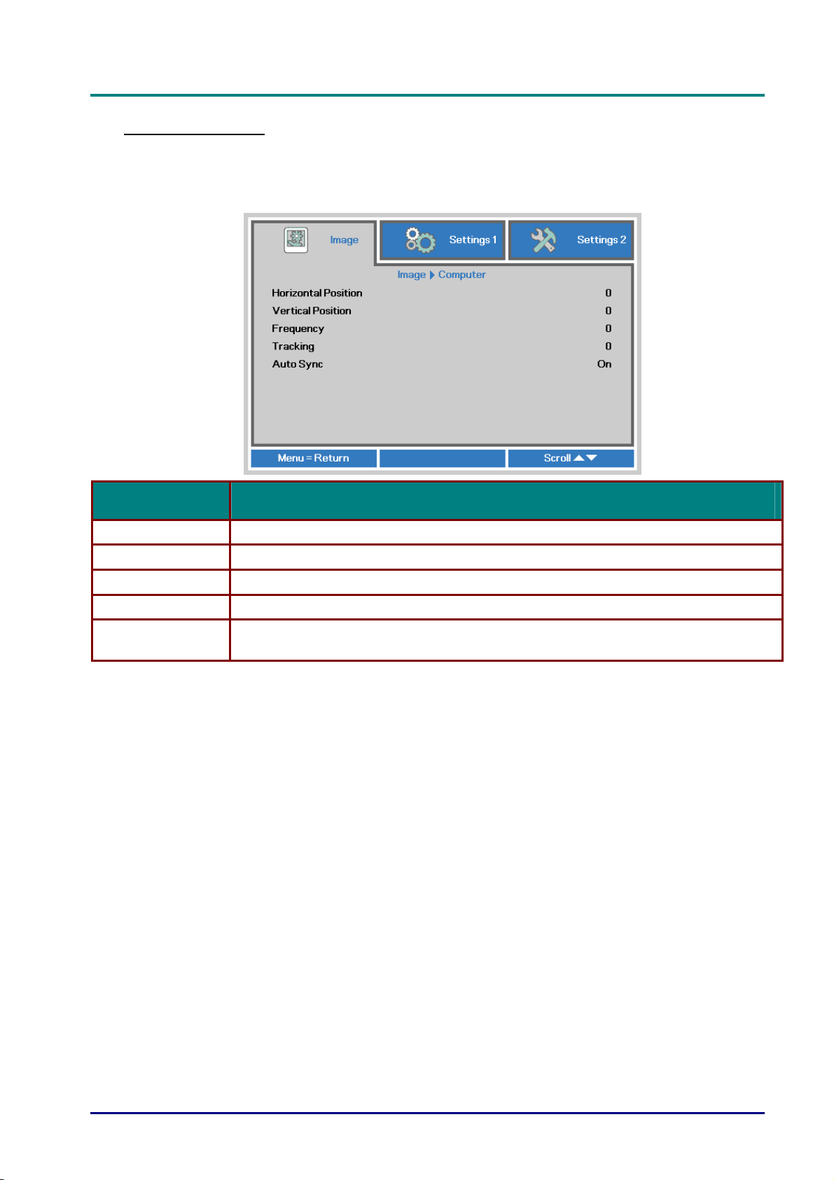
Press the MENU button to open the OSD menu. Press ◄► to move to the Image menu. Press
▲▼ to move to the Computer menu and then press Enter or ►. Press ▲▼ to move up and
down in the Computer menu.
ITEM DESCRIPTION
Horizontal Position Press the cursor ◄► button to enter and adjust the display position to left or right.
Vertical Position Press the cursor ◄► button to enter and adjust the display position to up or down.
Frequency Press the cursor ◄► button to enter and adjust the A/D sampling clock.
Tracking Press the cursor ◄► button to enter and adjust the A/D sampling dot.
Auto Sync
Press the cursor ◄► button to enter and enable or disable the autolock control for
RGB source.
— 28 —
Page 38
D
L
P
P
r
o
j
e
c
t
o
r
—
U
s
e
r
’
s
M
D
D
L
P
P
r
o
j
e
c
t
o
r
—
U
s
L
P
P
r
o
j
e
c
t
o
r
—
U
e
s
e
a
r
’
s
M
a
r
’
s
M
a
Advanced Feature
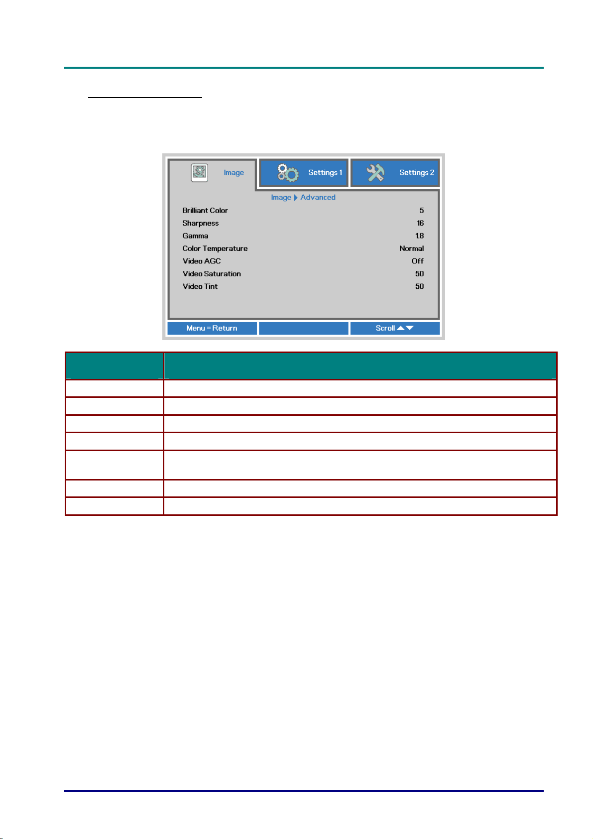
Press the Menu button to open the OSD menu. Press ◄► to move to the Image menu. Press
▼▲ to move to the Advanced menu and then press Enter or ►. Press ▼▲ to move up and
down in the Advanced menu.
n
u
a
l
n
u
a
l
n
u
a
l
ITEM DESCRIPTION
Brilliant Color Press the cursor ◄► button to enter and adjust the Brilliant Color value.
Sharpness Press the cursor ◄► button to enter and adjust the display sharpness.
Gamma Press the cursor ◄► button to enter and adjust the gamma correction of the display.
Color Temperature Press the cursor ◄► button to enter and adjust the color temperature.
Video AGC
Video Saturation Press the cursor ◄► button to enter and adjust the video saturation.
Video Tint Press the cursor ◄► button to enter and adjust the video tint/hue.
Press the cursor ◄► button to enter and enable or disable the Automatic Gain Control
for video source.
– 29 –
Page 39
DLP Projector—User’s Manual
Color Manager
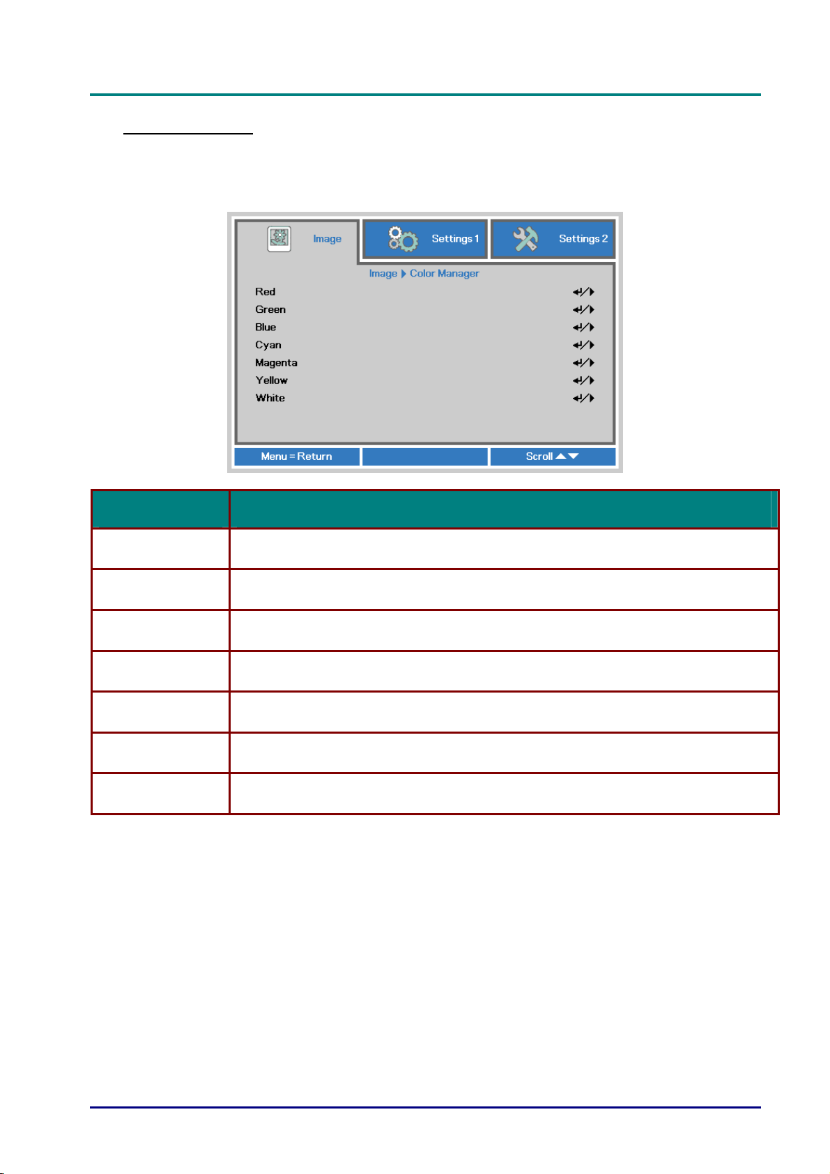
Press the Menu button to open the OSD menu. Press ◄► to move to the Image menu. Press
▼▲ to move to the Color Manager menu and then press Enter or ►. Press ▼▲ to move up and
down in the Color Manager menu.
Red
Green
Blue
Cyan
Magenta
Yellow
White
ITEM DESCRIPTION
Select to enter the Red Color Manager.
Press the ◄► buttons to adjust the Hue, Saturation, and Gain.
Select to enter the Green Color Manager.
Press the ◄► buttons to adjust the Hue, Saturation, and Gain.
Select to enter the Blue Color Manager.
Press the ◄► buttons to adjust the Hue, Saturation, and Gain.
Select to enter the Cyan Color Manager.
Press the ◄► buttons to adjust the Hue, Saturation, and Gain.
Select to enter the Magenta Color Manager.
Press the ◄► buttons to adjust the Hue, Saturation, and Gain.
Select to enter the Yellow Color Manager.
Press the◄► buttons to adjust the Hue, Saturation, and Gain.
Select to enter the White Color Manager.
Press the ◄► buttons to adjust the Red, Green, and Blue.
— 30 —
Page 40
D
L
P
P
r
o
j
e
c
t
o
r
—
D
D
L
P
P
r
o
j
e
L
P
c
P
r
o
j
e
c
U
t
o
r
—
U
t
o
r
—
U
Settings 1 Menu
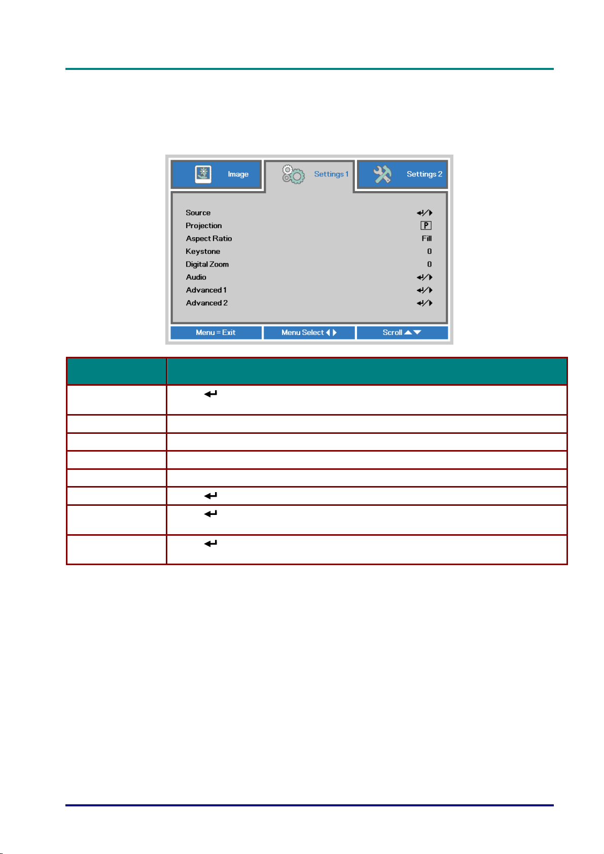
Press the MENU button to open the OSD menu. Press the cursor ◄► button to move to the
Settings 1 menu. Press the cursor ▲▼ button to move up and down in the Settings 1 menu.
Press ◄► to
enter and change values for settings.
s
e
r
’
s
M
a
n
u
a
l
s
e
r
’
s
M
s
e
r
’
s
M
a
n
u
a
l
a
n
u
a
l
ITEM DESCRIPTION
Source
Projection Press the cursor ◄► button to enter and choose from four projection methods:
Aspect Ratio Press the cursor ◄► button to enter and adjust the video aspect ratio.
Keystone Press the cursor ◄► button to enter and adjust the display keystone.
Digital Zoom Press the cursor ◄► button to enter and adjust the Digital Zoom menu.
Audio Press (Enter) / ► to enter the Audio menu. See Audio on page 32.
Advanced 1
Advanced 2
Press
(IR / Keypad).
Press
page 33.
Press
page 35.
(Enter) / ► to enter the Source menu. Reference input Source select
(Enter) / ► to enter the Advanced 1 menu. See Advanced 1 Feature on
(Enter) / ► to enter the Advanced 2 menu. See Advanced 2 Feature on
– 31 –
Page 41
DLP Projector—User’s Manual
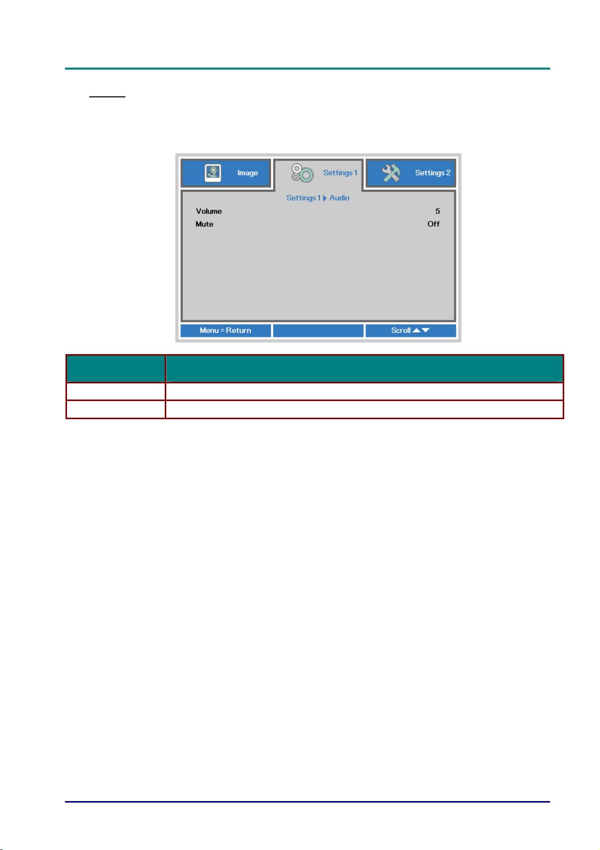
Audio
Press the Menu button to open the OSD menu. Press ◄► to move to the Settings 1 menu.
Press ▼▲ to move to the Audio menu and then press Enter or ►. Press ▼▲ to move up and
down in the Audio menu.
ITEM DESCRIPTION
Volume Press the cursor ◄► button to enter and adjust the audio volume.
Mute Press the cursor ◄► button to enter and turn on or off the speaker.
— 32 —
Page 42
D
L
P
P
r
o
j
e
c
t
o
r
—
U
s
e
r
’
s
M
a
n
D
D
L
P
P
r
o
j
e
c
t
o
r
—
U
s
e
r
’
L
P
P
r
o
j
e
c
t
o
r
—
U
s
s
e
r
’
u
M
a
n
s
u
M
a
n
u
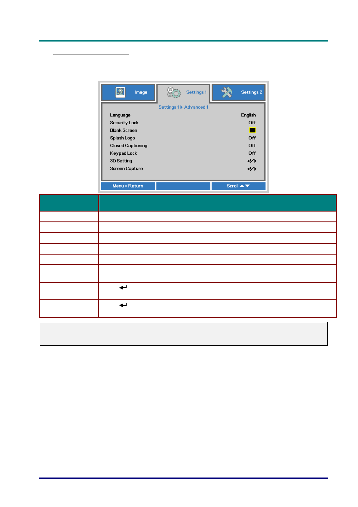
Advanced 1 Feature
Press the Menu button to open the OSD menu. Press ◄► to move to the Settings 1 menu.
Press ▲▼ to move to the Advanced 1 menu and then press Enter or ►. Press ▲▼ to move up
and down in the Advanced 1 menu. Press ◄► to enter and change values for setting.
ITEM DESCRIPTION
a
l
a
l
a
l
Language Press the cursor ◄► button to enter and select a different localization Menu.
Security Lock Press the cursor ◄► button to enter and enable or disable security lock function.
Blank Screen Press the cursor ◄► button to enter and select different color to blank the screen.
Splash Logo Press the cursor ◄► button to enter and select splash logo on or off.
Closed Captioning Press the cursor ◄► button to enter and enable or disable Closed Captioning
Keypad Lock
3D Setting
Screen Capture
Note:
To enjoy the 3D function, first enable the Play Movie in 3D setting found in your DVD device under
the 3D Disc Menu.
Press the cursor ◄► button to enter and enable or disable keys can be work on
keypad.
Press
Setting.
Press
Picture will auto showing after next power on.
(Enter) / ► to enter the 3D menu. See page 34 for more information on 3D
(Enter) / ► to capture screen, and please wait saving picture.
– 33 –
Page 43
DLP Projector—User’s Manual
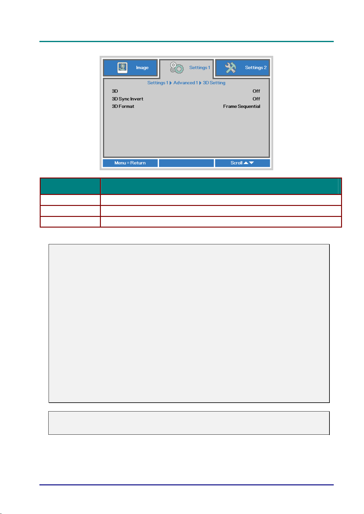
3D Setting
ITEM DESCRIPTION
3D Press the cursor ◄► button to enter and select different 3D mode.
3D Sync Invert Press the cursor ◄► button to enter and enable or disable 3D Sync Invert.
3D Format Press the cursor ◄► button to enter and enable or disable different 3D Format.
Note:
1. The 3D OSD menu item is gray if there is no appropriate 3D source. This is the default setting.
2. When the projector is connected to an appropriate 3D source, the 3D OSD menu item is enabled
for selection.
3. Use 3D glasses to view a 3D image.
4. You need 3D content from a 3D DVD or 3D media file.
5. You need to enable the 3D source (some 3D DVD content may have a 3D on-off selection
feature).
6. You need DLP link 3D or IR 3D shutter glasses. With IR 3D shutter glasses, you need to install a
driver on your PC and connect a USB emitter.
7. The 3D mode of the OSD needs to match the type of glasses (DLP link or IR 3D).
8. Power on the glasses. Glasses normally have a power on -off switch.
Each type of glasses has their own configuration instructions. Please follow the configuration
instructions that come with your glasses to finish the setup process.
Note:
Since different types of glass (DLP link or IR shutter glass) have their own setting instructions,
Please follow the guide to finish the setup process.
— 34 —
Page 44
D
L
P
P
r
o
j
e
c
t
o
r
—
U
s
e
r
’
s
M
a
n
D
D
L
P
P
r
o
j
e
c
t
o
r
—
U
s
e
r
’
L
P
P
r
o
j
e
c
t
o
r
—
U
s
s
e
r
’
u
M
a
n
s
u
M
a
n
u
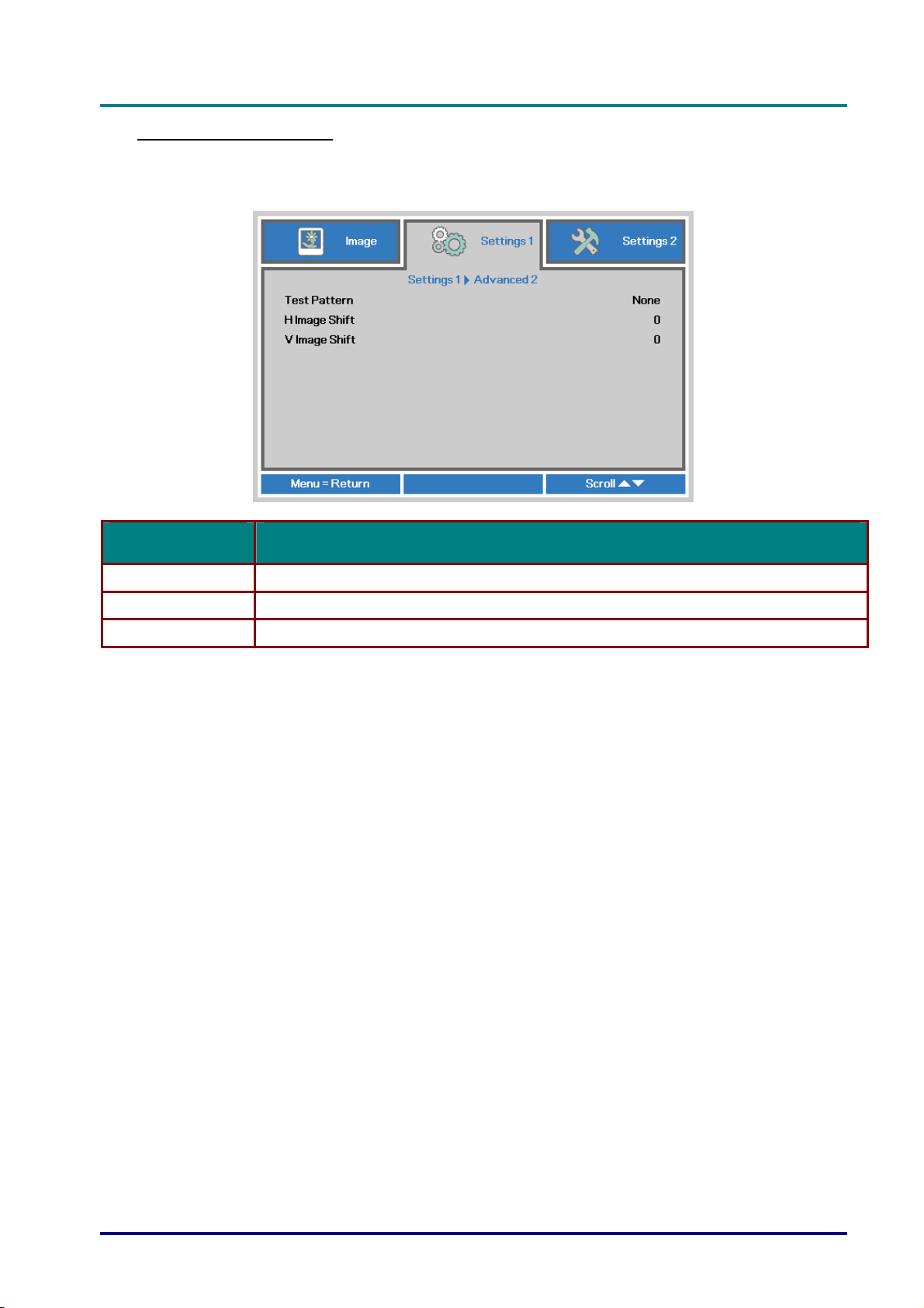
Advanced 2 Feature
Press the Menu button to open the OSD menu. Press ◄► to move to the Settings 1 menu.
Press ▲▼ to move to the Advanced 2 menu and then press Enter or ►. Press ▲▼ to move up
and down in the Advanced 2 menu. Press ◄► to enter and change values for setting.
a
l
a
l
a
l
ITEM DESCRIPTION
Test Pattern Press the cursor ◄► button to enter and select internal test pattern.
H Image Shift Press the cursor ◄► button to enter and select H Image Shift.
V Image Shift Press the cursor ◄► button to enter and select V Image Shift.
– 35 –
Page 45
DLP Projector—User’s Manual
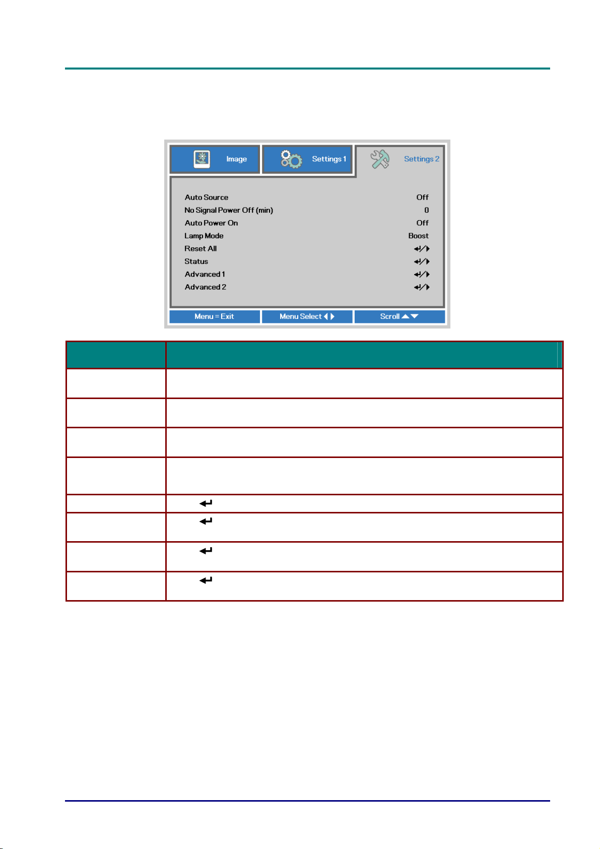
Settings 2 Menu
Press the MENU button to open the OSD menu. Press the cursor ◄► button to move to the
Settings 2 menu. Press the cursor ▲▼ button to move up and down in the Settings 2 menu.
ITEM DESCRIPTION
Auto Source
No Singal Power
Off (min.)
Auto Power On
Lamp Mode
Reset All Press (Enter) / ► to reset all settings to default values.
Status
Advanced 1
Advanced 2
Press the cursor ◄► button to enter and enable or disable automatic source
detection.
Press the cursor ◄► button to enter and enable or disable automatic shutdown of
lamp when no signal.
Press the cursor ◄► button to enter and enable or disable automatic power On when
AC power is supplied.
Press the cursor ◄► button to enter and select the lamp mode for higher brightness
or lower brightness to save lamp life.
Press
Status.
Press
page 38.
Press
page 50.
(Enter) / ► to enter the Status menu. See page 37 for more information on
(Enter) / ► to enter the Advanced 1 menu. See Advanced 1 Feature on
(Enter) / ► to enter the Advanced 2 menu. See Advanced 2 Feature on
— 36 —
Page 46
D
L
P
P
r
o
j
e
c
t
o
r
—
U
s
e
r
’
s
M
D
D
L
P
P
r
o
j
e
c
t
o
r
—
U
s
L
P
P
r
o
j
e
c
t
o
r
—
U
e
s
e
a
r
’
s
M
a
r
’
s
M
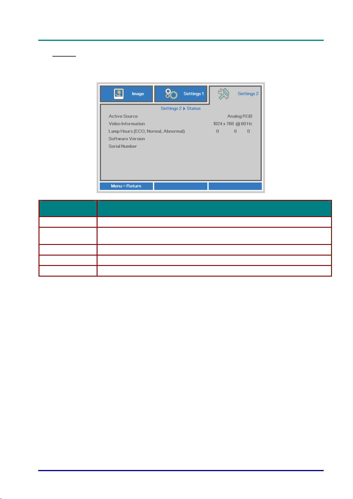
Status
Press the cursor ▲▼ button to move up and down in the Settings 2 menu. Select the Status
menu and press Enter or ► to enter.
n
u
a
l
n
u
a
l
a
n
u
a
l
ITEM DESCRIPTION
Active Source Display the activated source.
Video Information
Lamp Hours Lamp hour used information is displayed. (ECO, Normal, Abnormal )
Software Version Showing system software version.
Serial Number Showing serial number of this projector.
Displays resolution/video information for RGB source and color standard for Video
source.
– 37 –
Page 47
DLP Projector—User’s Manual
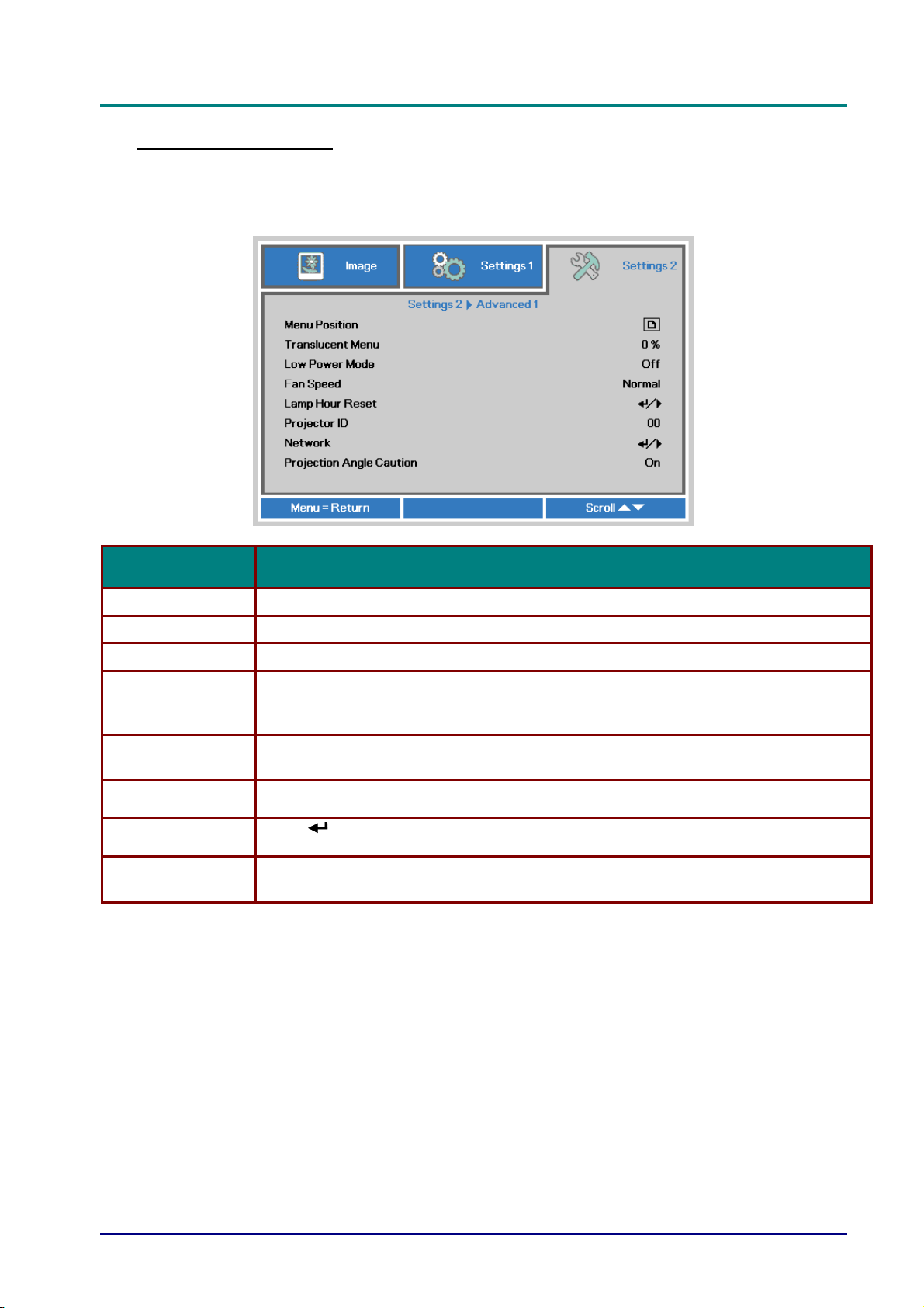
Advanced 1 Feature
Press the Menu button to open the OSD menu. Press ◄► to move to the Settings 2 menu.
Press ▲▼ to move to the Advanced 1 menu and then press Enter or ►. Press ▲▼ to move up
and down in the Advanced 1 menu. Press ◄► to
enter and change values for setting.
ITEM DESCRIPTION
Menu Position Press the cursor ◄► button to enter and select different OSD location.
Translucent Menu Press the cursor ◄► button to enter and select OSD background translucent level.
Low Power Mode Press the cursor ◄► button to enter and turn Low Power Mode on or off.
Press the cursor ◄► button to enter and toggle between Normal and High fan speeds.
Fan Speed
Lamp Hour Reset
Projector ID
Network
Projection Angle
Caution
Note: We recommend selecting high speed in high temperatures, high humidity, or
high altitude (higher than 1500m/4921ft) areas.
After replacing the lamp, this item should be reset. See page 39 for more information
on Lamp Hour Reset.
Press the cursor ◄► button to enter and adjust a two digit projector ID from 00
through 98.
Press
(Enter) / ► to enter the Network menu. See page 39 for more information on
Network.
Press the cursor ◄► button to enter and turn Projection Angle Caution on or off.
— 38 —
Page 48
D
L
P
P
r
o
j
e
c
t
D
L
P
P
D
L
P
P
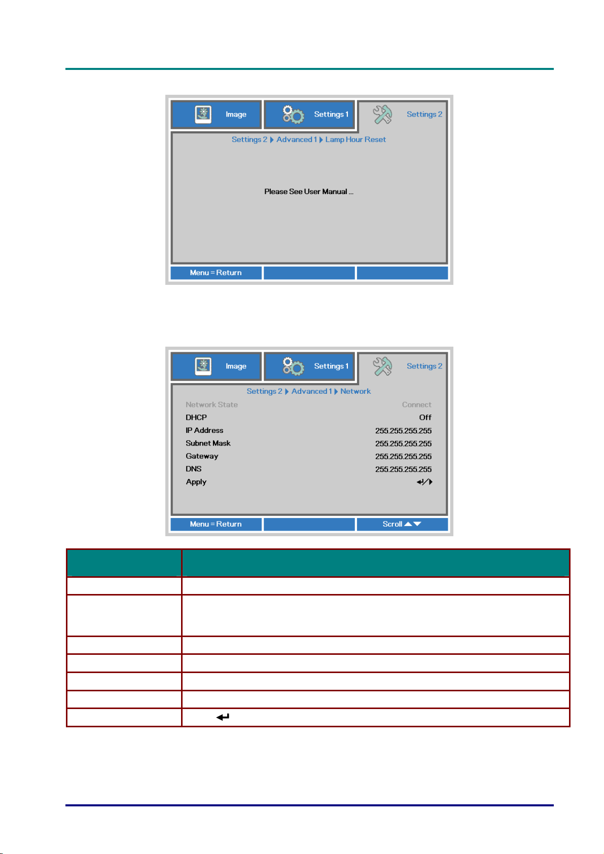
Lamp Hour Reset
Please refer to Resetting the Lamp on page 57 to reset the lamp hour counter.
Network
o
r
o
j
e
c
t
o
r
o
j
e
c
t
o
r
—
U
s
e
r
’
s
M
a
n
u
a
l
r
—
U
s
e
r
’
s
r
—
U
M
s
e
r
’
s
M
a
n
u
a
l
a
n
u
a
l
ITEM DESCRIPTION
Network State Displays the network connection status.
Press the cursor ◄► button to turn DHCP On or Off.
DHCP
IP Address Enter a valid IP address if DHCP is turned off.
Subnet Mask Enter a valid Subnet Mask if DHCP is turned off.
Gateway Enter a valid Gateway address if DHCP is turned off.
DNS Enter a valid DNS name if DHCP is turned off.
Apply Press (Enter) / ► to confirm settings.
Note: If you select DHCP Off, complete the IP Address, Subnet Mask, Gateway,
and DNS fields.
– 39 –
Page 49
DLP Projector—User’s Manual
LAN_RJ45
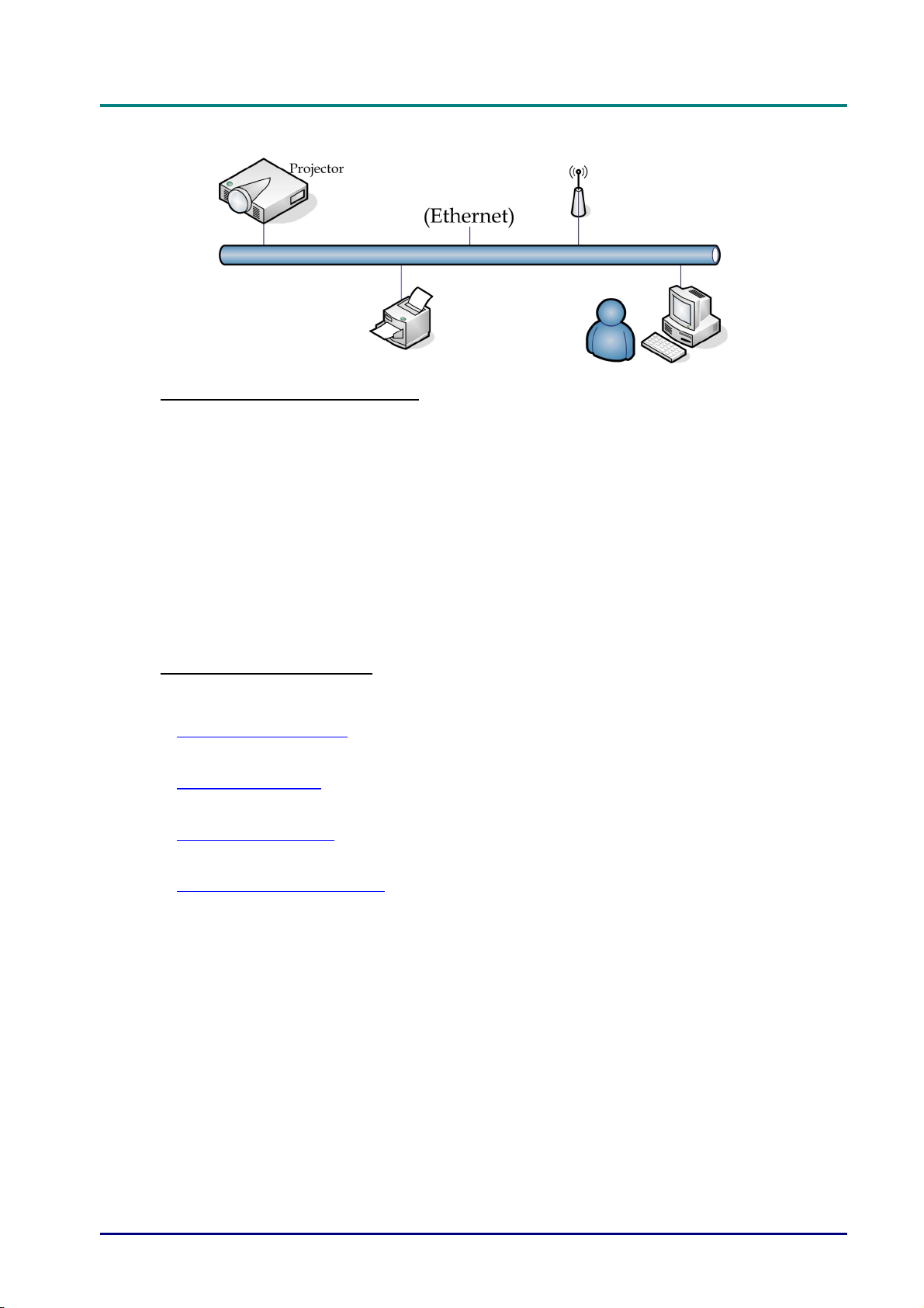
Wired LAN Terminal functionalites
Remote control and monitoring of a projector from a PC (or Laptop) via wired LAN is also possible.
Compatibility with Crestron / AMX (Device Discovery) / Extron control boxes enables not only
collective projector management on a network but also management from a control panel on a PC
(or Laptop) browser screen.
Crestron is a registered trademark of Crestron Electronics, Inc. of the United States.
Extron is a registered trademark of Extron Electronics, Inc. of the United States.
AMX is a registered trademark of AMX LLC of the United States.
PJLink applied for trademark and logo registration in Japan, the United States of America, and
other countries by JBMIA.
Supported External Devices
This projector is supported by the specified commands of the Crestron Electronics controller and
related software (ex, RoomView ®).
http://www.crestron.com/
This projector is supported by AMX ( Device Discovery ).
http://www.amx.com/
This projector is compliant to support Extron device(s) for reference.
http://www.extron.com/
This projector supports all commands of PJLink Class1 (Version 1.00).
http://pjlink.jbmia.or.jp/english/
For more detail of information about the diverse types of external devices which can be connected to
the LAN/RJ45 port and remote/control the projector, as well as the related control commands
supporting for each external device, kindly please get contact with the Support-Service team directly.
— 40 —
Page 50
D
L
P
P
r
o
j
e
c
t
o
r
D
L
P
P
r
D
L
LAN_RJ45
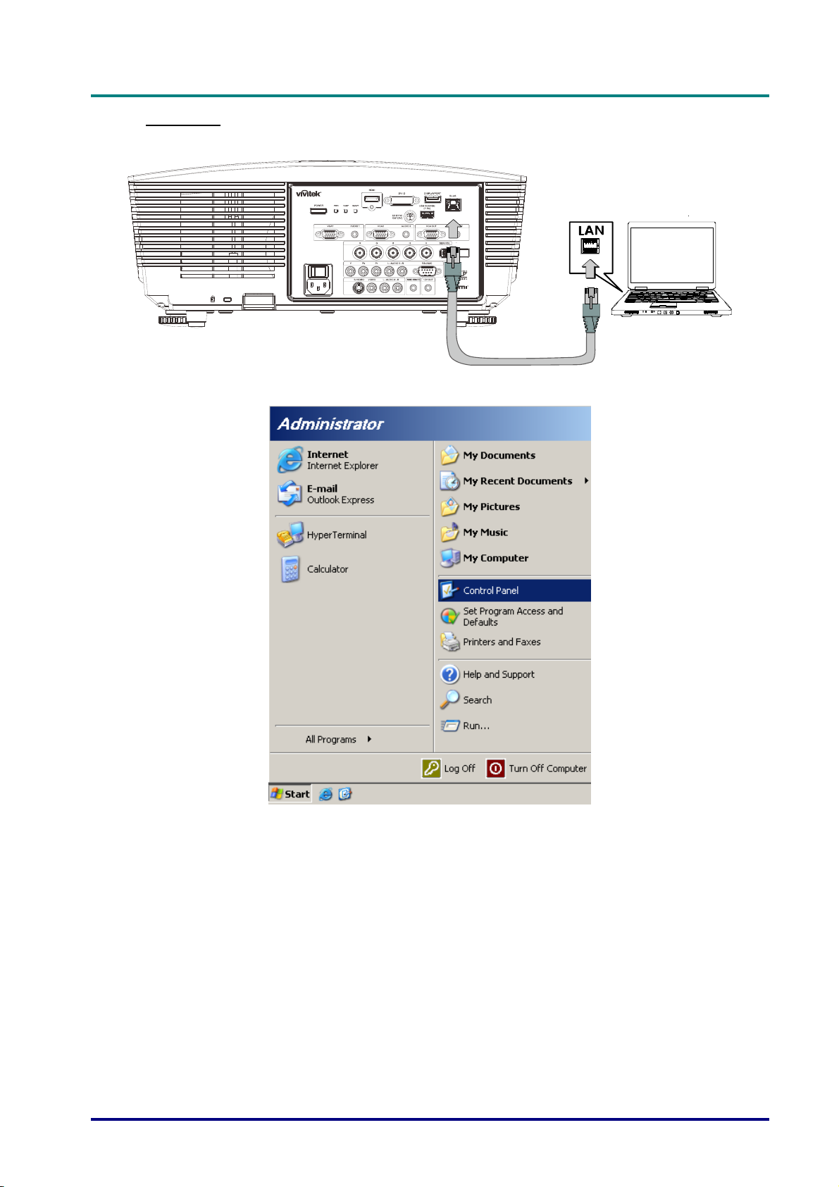
1. Connect an RJ45 cable to RJ45 ports on the projector and the PC (Laptop).
2. On the PC (Laptop), select Start → Control Panel → Network Connections.
o
P
P
r
o
—
j
e
c
t
o
r
—
j
e
c
t
o
r
—
U
U
U
s
e
r
’
s
M
a
n
u
a
l
s
e
r
’
s
M
s
e
r
’
s
M
a
n
u
a
l
a
n
u
a
l
– 41 –
Page 51
DLP Projector—User’s Manual
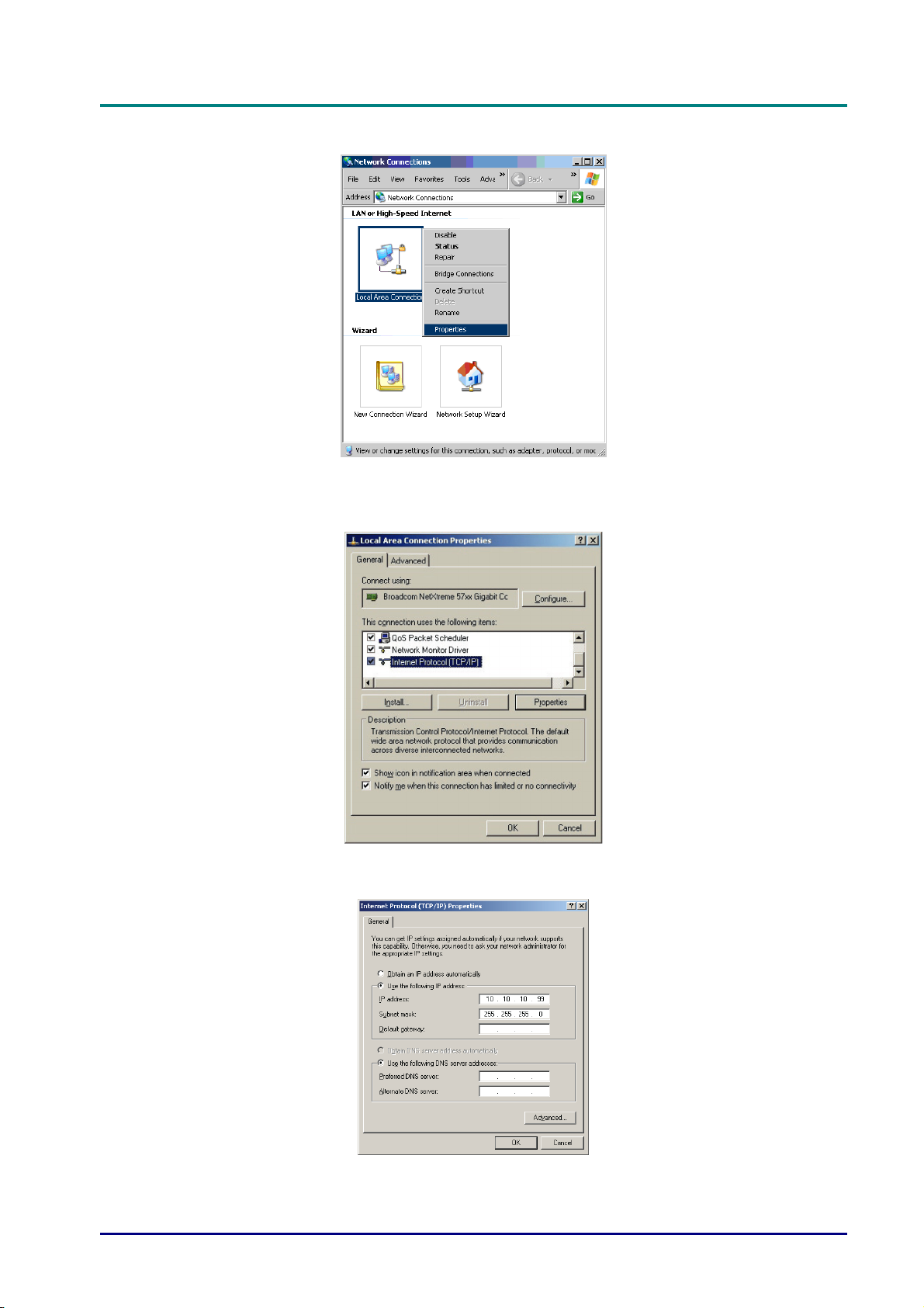
3. Right-click on Local Area Connection, and select Properties.
4. In the Properties window, select the General tab, and select Internet Protocol (TCP/IP).
5. Click Properties.
6. Click Use the following IP address and fill in the IP address and Subnet mask, then click OK.
— 42 —
Page 52
7. Press the Menu button on the projector.
8. Select Settings2→ Advanced1 → Network
9. After getting into Network, input the following:
` DHCP: Off
` IP Address: 10.10.10.10
` Subnet Mask: 255.255.255.0
` Gateway: 0.0.0.0
` DNS Server: 0.0.0.0
D
D
D
L
P
P
r
o
j
e
c
t
o
r
—
U
s
e
r
’
s
M
a
n
u
a
l
L
P
P
r
o
j
e
c
t
o
r
—
U
s
e
r
’
s
L
P
P
r
o
j
e
c
t
o
r
—
U
M
s
e
r
’
s
M
a
n
u
a
l
a
n
u
a
l
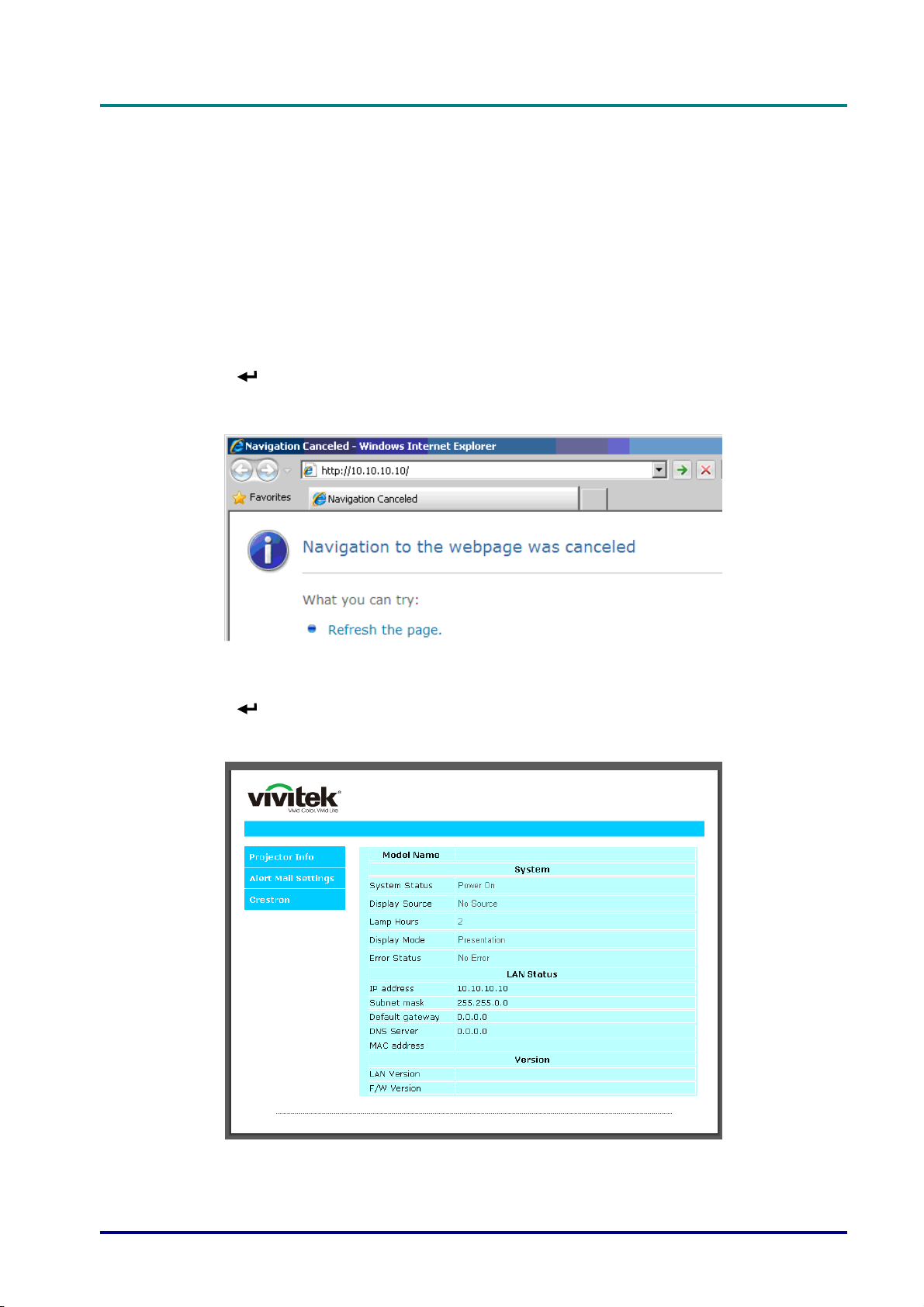
10. Press
Open a web browser
(for example, Microsoft Internet Explorer with Adobe Flash Player 9.0 or higher).
11. In the Address bar, input the IP address: 10.10.10.10.
12. Press
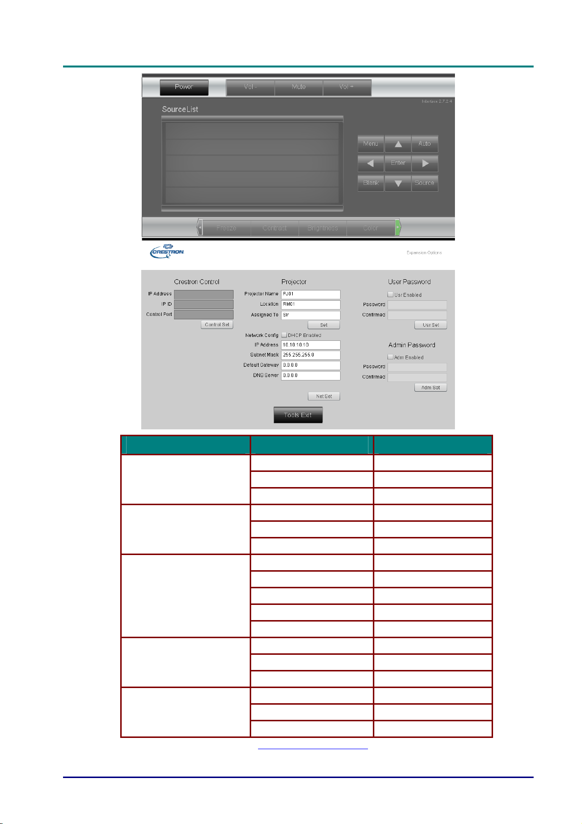
The projector is setup for remote management. The LAN/RJ45 function displays as follows.
(Enter) / ► to confirm settings.
(Enter) / ►.
– 43 –
Page 53
DLP Projector—User’s Manual
CATEGORY ITEM INPUT-LENGTH
Crestron Control
Projector
Network Configuration
User Password
Admin Password
IP Address 15
IP ID 3
Port 5
Projector Name 10
Location 10
Assigned To 10
DHCP (Enabled) (N/A)
IP Address 15
Subnet Mask 15
Default Gateway 15
DNS Server 15
Enabled (N/A)
New Password 10
Confirm 10
Enabled (N/A)
New Password 10
Confirm 10
For more information, please visit http://www.crestron.com.
— 44 —
Page 54
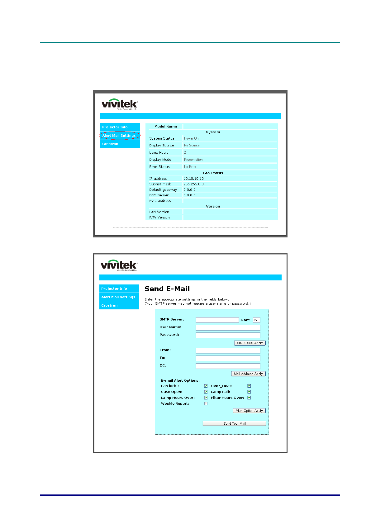
D
L
P
P
r
o
j
e
c
t
o
r
—
U
s
e
r
’
s
M
a
D
D
L
P
P
r
o
j
e
c
t
o
r
—
U
s
e
L
P
P
r
o
j
e
c
t
o
r
—
U
r
s
e
r
n
’
s
M
a
n
’
s
M
a
n
Preparing Email Alerts
1. Make sure that user can access the homepage of LAN RJ45 function by web browser (for example, Microsoft Internet Explorer v6.01/v8.0).
2. From the Homepage of LAN/RJ45, click Alert Settings.
u
a
l
u
a
l
u
a
l
3. By default, these input boxes in Alert Settings are blank.
– 45 –
Page 55
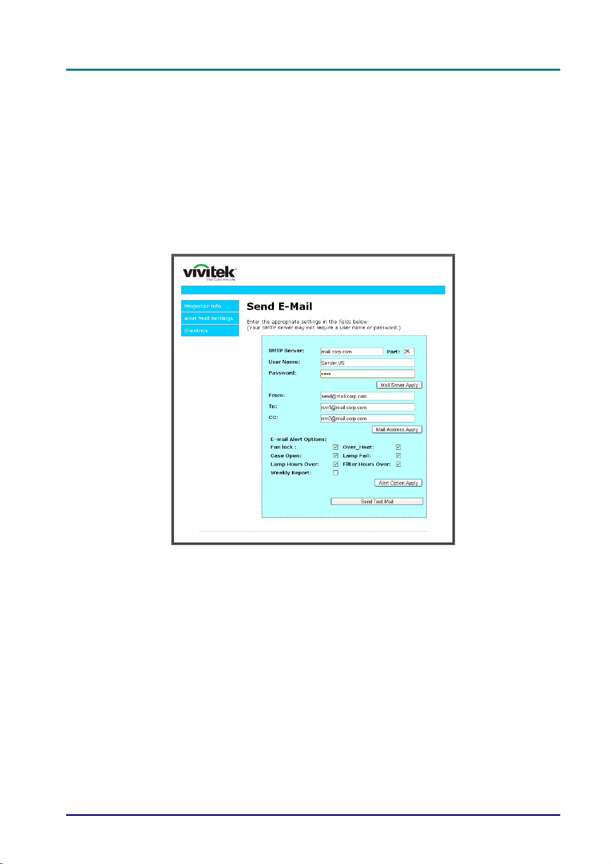
DLP Projector—User’s Manual
4. For Sending alert mail, input the following:
The SMTP field is the mail server for sending out email (SMTP protocol). This is a required
field.
The To field is the recipient’s email address (for example, the projector administrator). This is
a required field.
The Cc field sends a carbon copy of the alert to the specified email address. This is an
optional field (for example, the projector administrator’s assistant).
The From field is the sender’s email address (for example, the projector administrator). This is
a required field.
Select th e alert conditions by checking the desired boxes.
Note: Fill in all fields as specified. User can click Send Test Mail to test what setting is correct.
For successful sending an e-mail alert, you must select alert conditions and enter a correct e-mail
address.
— 46 —
Page 56
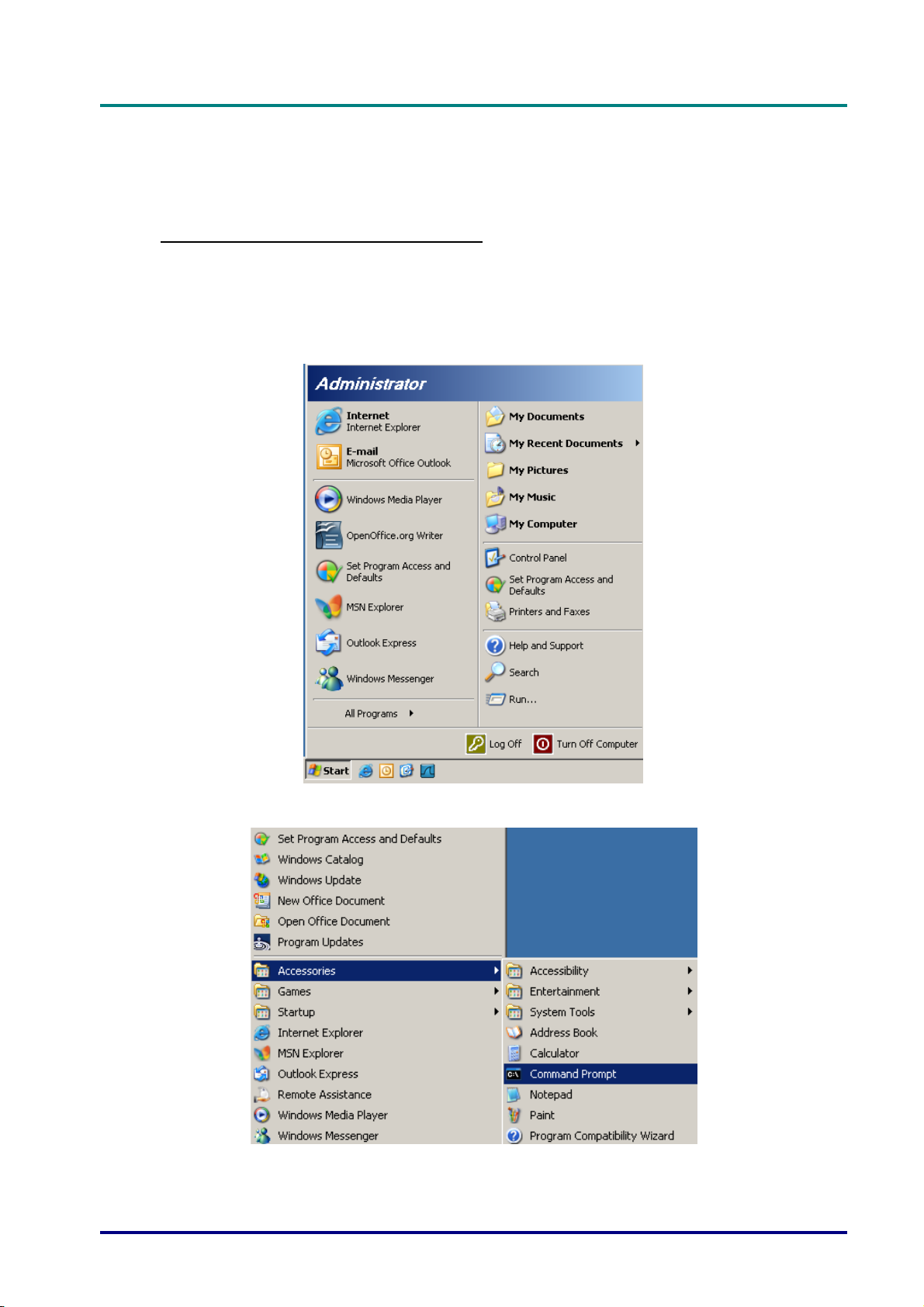
D
L
P
P
r
o
j
e
c
t
o
r
—
U
s
e
r
’
s
M
a
D
D
L
P
P
r
o
j
e
c
t
o
r
—
U
s
e
L
P
P
r
o
j
e
c
t
o
r
—
U
r
s
e
r
n
’
s
M
a
n
’
s
M
a
n
RS232 by Telnet Function
Besides projector connected to RS232 interface with “Hyper-Terminal” communication by
dedicated RS232 command control, there is alternative RS232 command control way, so called
“RS232 by TELNET” for LAN/RJ45 interface.
Quick Start-Guide for “RS232 by TELNET”
Check and get the IP-Address on OSD of the projector.
Make sure that laptop/PC can access the web-page of the projector.
Make sure that “Windows Firewall” setting to be disabled in case of “TELNET” function filtering
out by laptop/PC.
u
a
l
u
a
l
u
a
l
Start => All Programs => Accessories => Command Prompt
– 47 –
Page 57
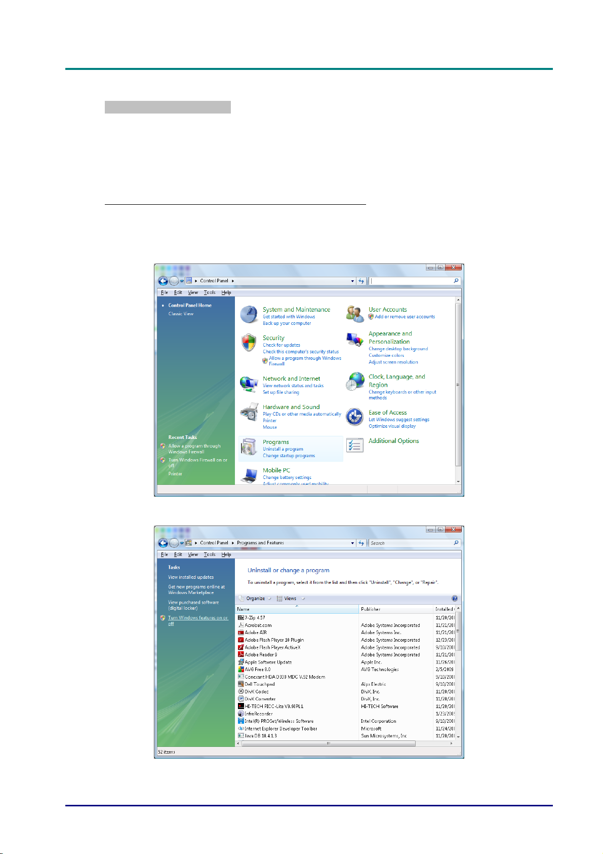
DLP Projector—User’s Manual
Input the command format like the below:
telnet ttt.xxx.yyy.zzz 23 (“Enter” key pressed)
(ttt.xxx.yyy.zzz: IP-Address of the projector)
If Telnet-Connection ready, and user can have RS232 command input, then “Enter” key
pressed, the RS232 command will be workable.
How to have TELNET enabled in Windows VISTA / 7
By default installation for Windows VISTA, “TELNET” function is not included. But end-user
can have it by way of “Turn Windows features On or Off” to be enabled.
Open “Control Panel” in Windows VISTA
Open “Programs”
— 48 —
Page 58
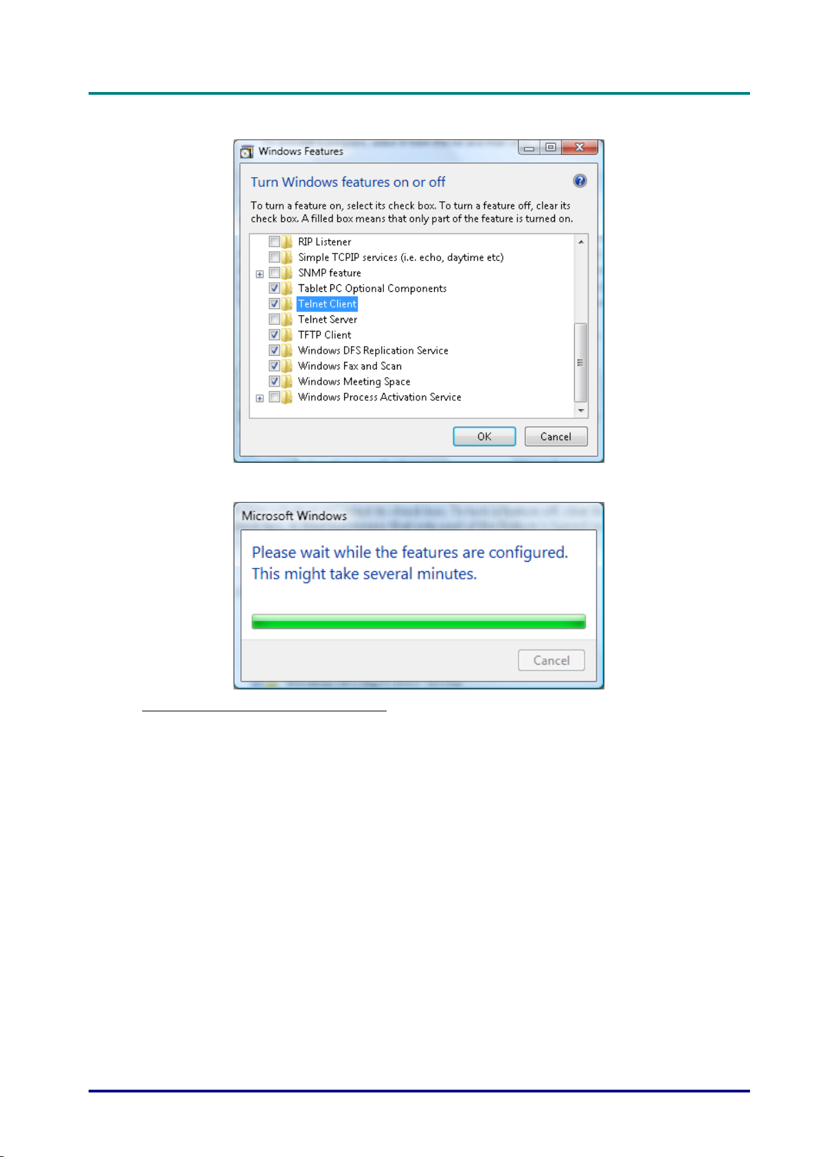
Select “Turn Windows features on or off” to open
D
D
D
L
P
P
r
o
j
e
c
t
o
r
—
U
s
e
r
’
s
M
a
n
u
a
l
L
P
P
r
o
j
e
c
t
o
r
—
U
s
e
r
’
s
L
P
P
r
o
j
e
c
t
o
r
—
U
M
s
e
r
’
s
M
a
n
u
a
l
a
n
u
a
l
Have “Telnet Client” option checked, then press “OK” button.
Specsheet for “RS232 by TELNET” :
1. Telnet: TCP
2. Telnet port: 23
(for more detail, kindly please get contact with the service agent or team)
3. Telnet utility: Windows “TELNET.exe” (console mode)
4. Disconnection for RS232-by-Telnet control normally: Close Windows Telnet utility directly
after TELNET connection ready
5. Limitation 1 for Telnet-Control: there is less than 50 bytes for successive network payload
for Telnet-Control application.
Limitation 2 for Telnet-Control: there is less than 26 bytes for one complete RS232
command for Telnet-Control.
Limitation 3 for Telnet-Control: Minimum delay for next RS232 command must be more
than 200 (ms).
(*, In Windows XP built-in “TELNET.exe” utility, “Enter” key pressed will have “CarriageReturn” and “New-Line” code.)
– 49 –
Page 59
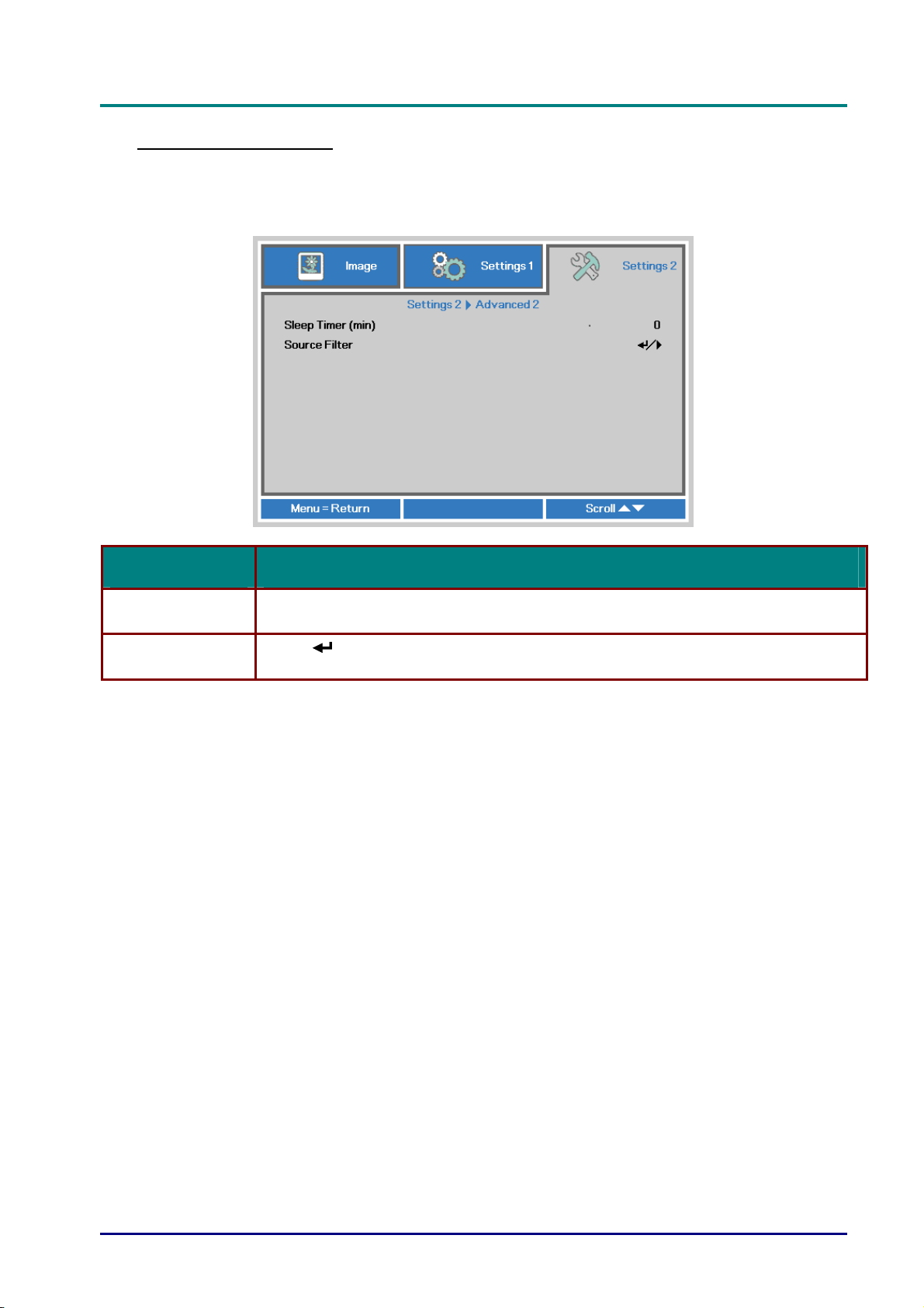
DLP Projector—User’s Manual
Advanced 2 Feature
Press the Menu button to open the OSD menu. Press ◄► to move to the Settings 2 menu.
Press ▲▼ to move to the Advanced 2 menu and then press Enter or ►. Press ▲▼ to move up
and down in the Advanced 2 menu. Press ◄► to
enter and change values for setting.
ITEM DESCRIPTION
Sleep Timer (min)
Source Filter
Press the cursor ◄► button to enter and set Sleep timer. The projector automatically
turns off after the preset period of time.
Press
information on Source Filter.
(Enter) / ► to enter the Source Filter menu. See page 51 for more
— 50 —
Page 60
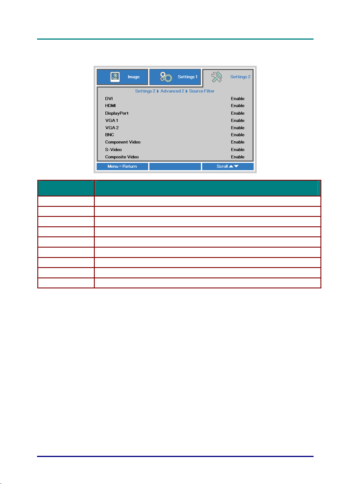
Source Filter
Press the ENTER button to enter the Source Filter sub menu.
ITEM DESCRIPTION
D
D
D
L
P
P
r
o
j
e
c
t
o
r
—
U
s
e
r
’
s
M
a
n
u
a
l
L
P
P
r
o
j
e
c
t
o
r
—
U
s
e
r
’
s
L
P
P
r
o
j
e
c
t
o
r
—
U
M
s
e
r
’
s
M
a
n
u
a
l
a
n
u
a
l
DVI Press the ◄► buttons to enter and enable or disable the DVI source.
HDMI Press the ◄► buttons to enter and enable or disable the HDMI source.
DisplayPort Press the ◄► buttons to enter and enable or disable the DisplayPort source.
VGA1 Press the ◄► buttons to enter and enable or disable the VGA1 source.
VGA2 Press the ◄► buttons to enter and enable or disable the VGA2 source.
BNC Press the ◄► buttons to enter and enable or disable the BNC source.
Component Video Press the ◄► buttons to enter and enable or disable the Component Video source.
S-Video Press the ◄► buttons to enter and enable or disable the S-Video source.
Composite Video Press the ◄► buttons to enter and enable or disable the Composite Video source.
– 51 –
Page 61
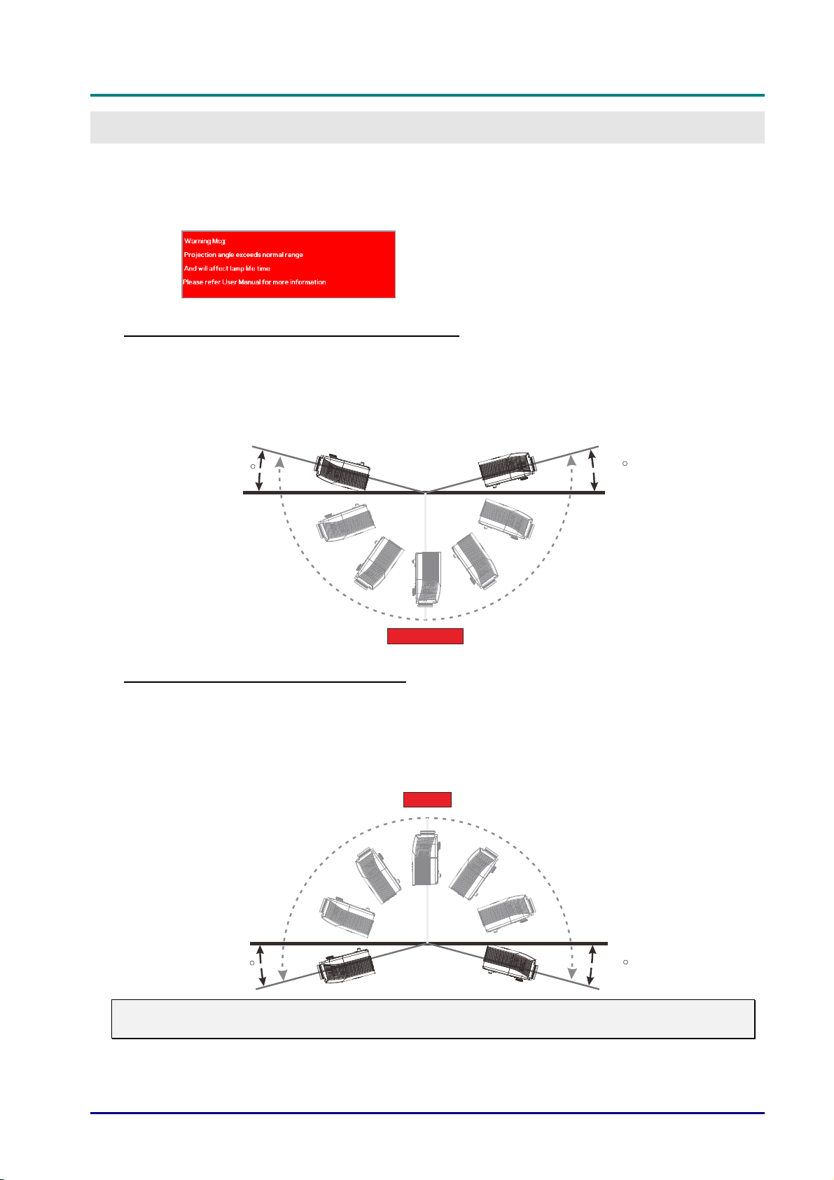
DLP Projector—User’s Manual
MAINTENANCE AND SECURITY
Tilt Up/Down caution
¾ When projector detect angle is over spec, popup caution message.
The model with Standard lamp module
The model with Standard lamp module can be used projection angle as shown below.
If Projector projection angle exceeds the drawing shown and don’t use tilt lamp module. Showing caution
message for 5sec and then disappear, projector remain on. (every time when projector on
can be disable see
Advanced 1 Feature on page 38 )
; This function
15
Standard Lamp
15
The model with Tilt lamp module
The model with Tilt lamp module can be used projection angle as shown below.
If Projector projection angle exceeds the drawing shown and don’t use standard lamp module. Showing
caution message for 5sec and then disappear, projector remain on. (every time when projector on
function can be disable see
Advanced 1 Feature on page 38 )
Tilt Lamp
; This
15
Warning:
Your operation might cause lamp defect and life decay. If used incorrect lamp module
— 52 —
15
Page 62
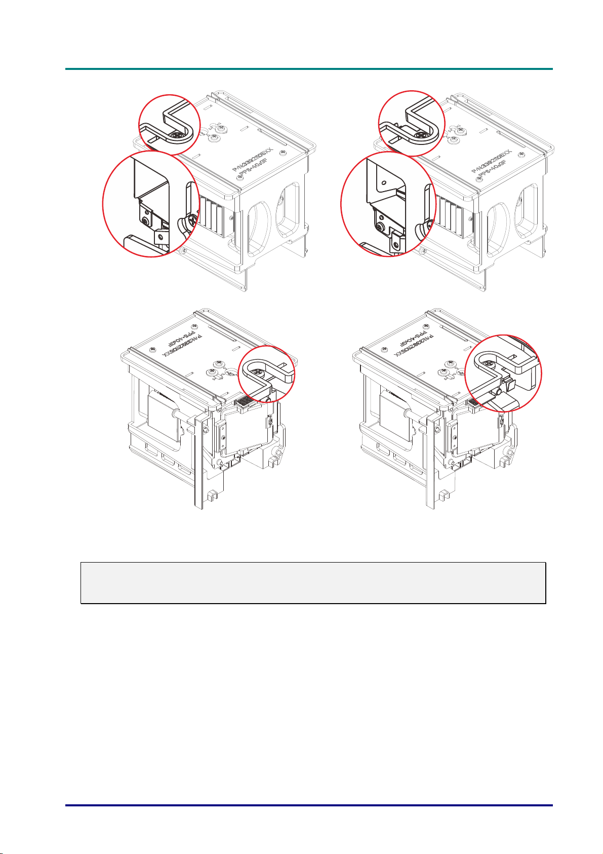
D
D
D
L
P
P
r
o
j
e
c
t
o
r
—
U
s
e
r
’
s
M
a
n
u
a
l
L
P
P
r
o
j
e
c
t
o
r
—
U
s
e
r
’
s
L
P
P
r
o
j
e
c
t
o
r
—
U
M
s
e
r
’
s
M
a
n
u
a
l
a
n
u
a
l
Standard lamp module
Note:
The standard lamp is to go with regular shipment for normal operation and the tilt lamp is an
option lamp for abnormal operation
Tilt lamp module
( Optional )
– 53 –
Page 63
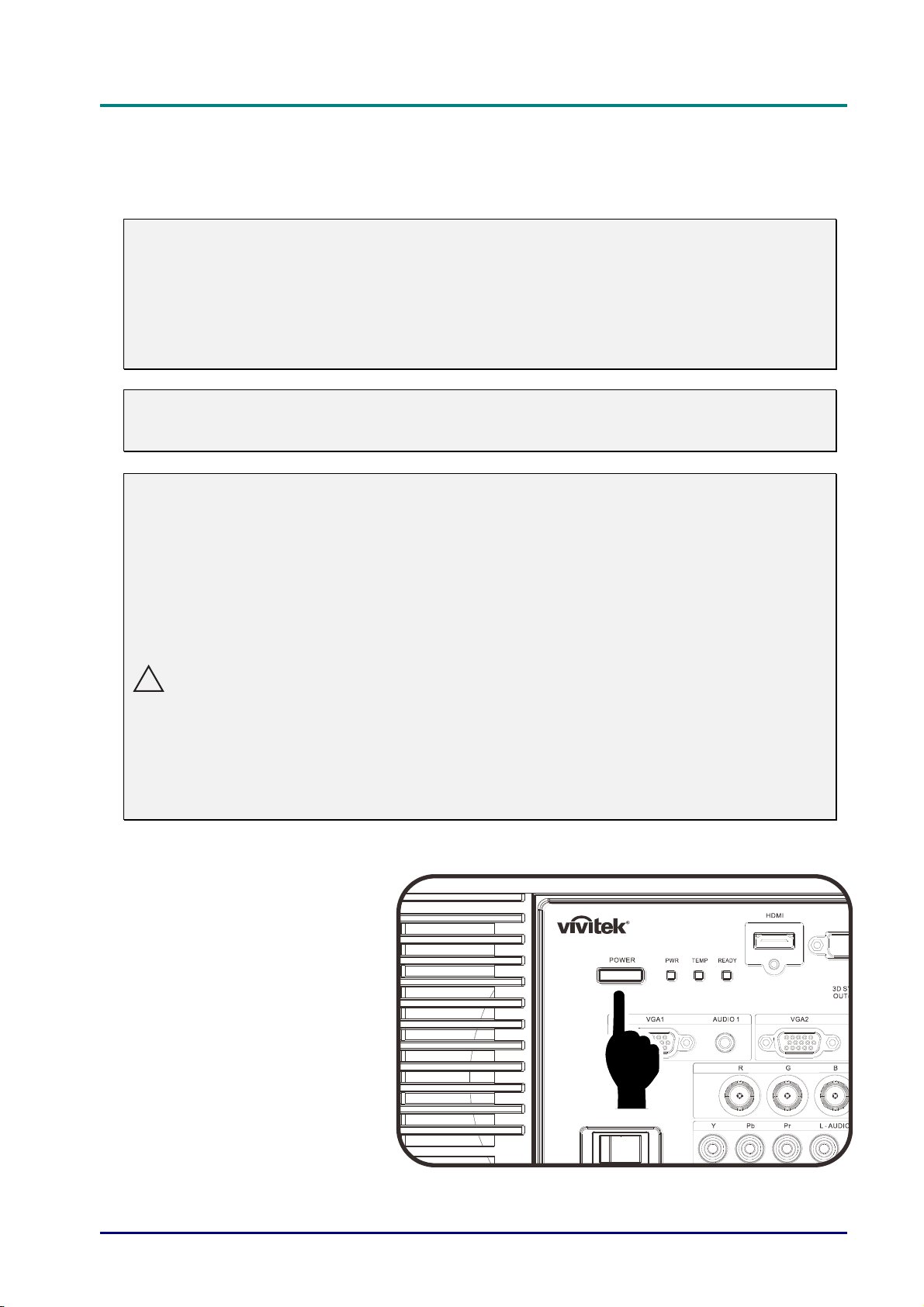
DLP Projector—User’s Manual
Replacing the Projection Lamp
The projection lamp should be replaced when it burns out. It should only be replaced with a
certified replacement part, which you can order from your local dealer.
Important:
a. The projection lamp used in this product contains a small amount of mercury.
b. Do not dispose this product with general household waste.
c. Disposal of this product must be carried out in accordance with the regulations of your local
authority.
Warning:
Be sure to turn off and unplug the projector at least 30 minutes before replacing the lamp.
Failure to do so could result in a severe burn.
Caution:
In rare cases the lamp bulb may burn out during normal operation and cause glass dust or
shards to be discharged outward from the rear exhaust vent.
Do not inhale or do not touch glass dust or shards. Doing so could result in injury.
Always keep your face away from the exhaust vent so that you do not suffer from the gas and
broken shards of the lamp.
When removing the lamp from a ceiling-mounted projector, make sure that no one is under the
projector. Glass fragments could fall if the lamp has been burned out.
!
IF A LAMP EXPLODES
If a lamp explodes, the gas and broken shards may scatter inside the projector and they may
come out of the exhaust vent. The gas contains toxic mercury.
Open windows and doors for ventilation.
If you inhale the gas or the shards of the broken lamp enter your eyes or mouth, consult the
doctor immediately.
Switch off the power to the
1.
projector by pressing the
POWER button.
Allow the projector to cool
2.
down at least 30 minutes.
Disconnect the power
3.
cord.
— 54 —
Page 64
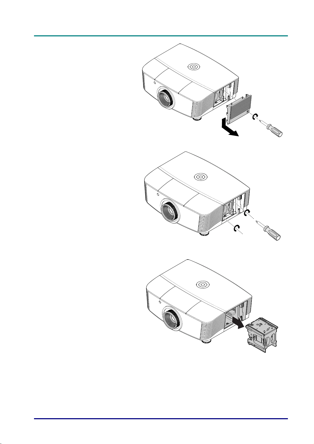
Unlock the lamp cover.
4.
Pull up and remove the
5.
cover.
Use a screwdriver to
6.
remove the screws from
the lamp module.
D
D
D
L
P
P
r
o
j
e
c
t
o
r
—
U
s
e
r
’
s
M
a
n
u
a
l
L
P
P
r
o
j
e
c
t
o
r
—
U
s
e
r
’
s
L
P
P
r
o
j
e
c
t
o
r
—
U
M
s
e
r
’
s
M
a
n
u
a
l
a
n
u
a
l
Pull out the lamp module.
7.
– 55 –
Page 65
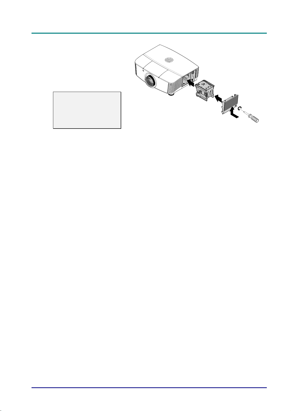
DLP Projector—User’s Manual
Reverse steps 1 to 7 to
8.
install the new lamp
module.
While installing, align the
lamp module with the
connector and ensure it is
level to avoid damage.
Note:
The lamp module must sit
securely in place and the
lamp connector must be
connected properly before
tightening the screws.
— 56 —
Page 66
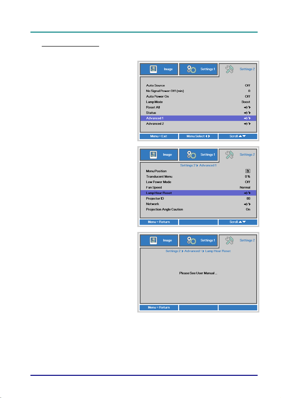
D
L
P
P
r
o
j
e
c
t
o
r
—
U
s
e
r
’
s
M
D
D
L
P
P
r
o
j
e
c
t
o
r
—
U
s
L
P
P
r
o
j
e
c
t
o
r
—
U
e
s
e
a
r
’
s
M
a
r
’
s
M
a
Resetting the Lamp
After replacing the lamp, you should reset the lamp hour counter to zero. Refer to the following:
Press the MENU button to open
1.
the OSD menu.
Press the cursor ◄► button to
2.
move to the Settings 2 menu.
Press the cursor button to move
down to Advanced 1 and press
enter.
Press the cursor ▼▲ button to
3.
move down to Lamp Hour Reset.
n
u
a
l
n
u
a
l
n
u
a
l
Press the cursor ► or Enter
4.
button.
A message screen appears.
Press ▼▲◄► buttons to reset
5.
the lamp hour.
Press the MENU button to get
6.
back to Settings 2.
– 57 –
Page 67
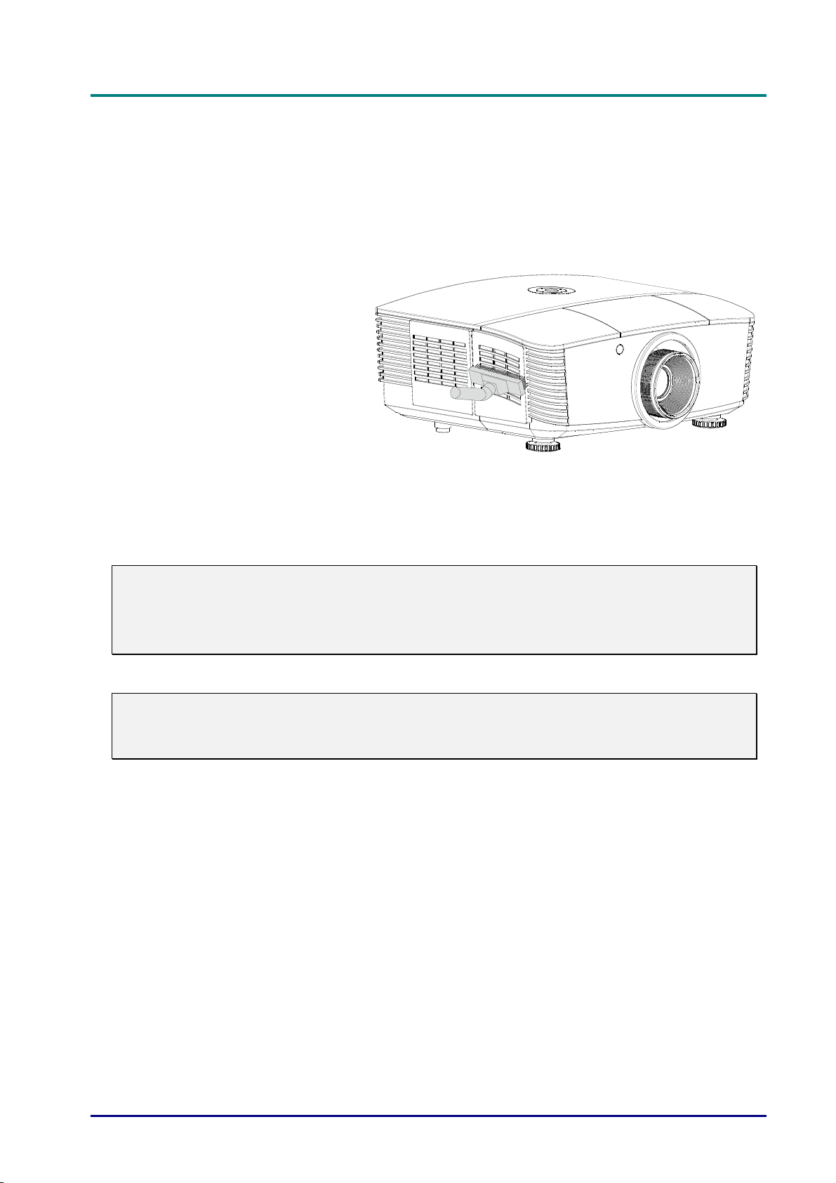
DLP Projector—User’s Manual
Cleaning the filter (filter: optional parts)
The air filter prevents dust from accumulating on the surface of the optical elements inside the
projector. If the filter is dirty or clogged, your projector may overheat or degrading the projected
image quality.
Turn off the projector, and
1.
unplug the AC power cord
from the AC outlet.
Cleaning the filter with a
2.
vacuum cleaner.
Caution:
Recommend avoiding dusty or smoky environments when you operate the projector, it may
cause poor image quality.
If the filter is heavily clogged and unable to clean, replace a new filter.
Note:
Using a ladder is recommended to access the filter. Do not remove the projector from the
wall mount.
— 58 —
Page 68
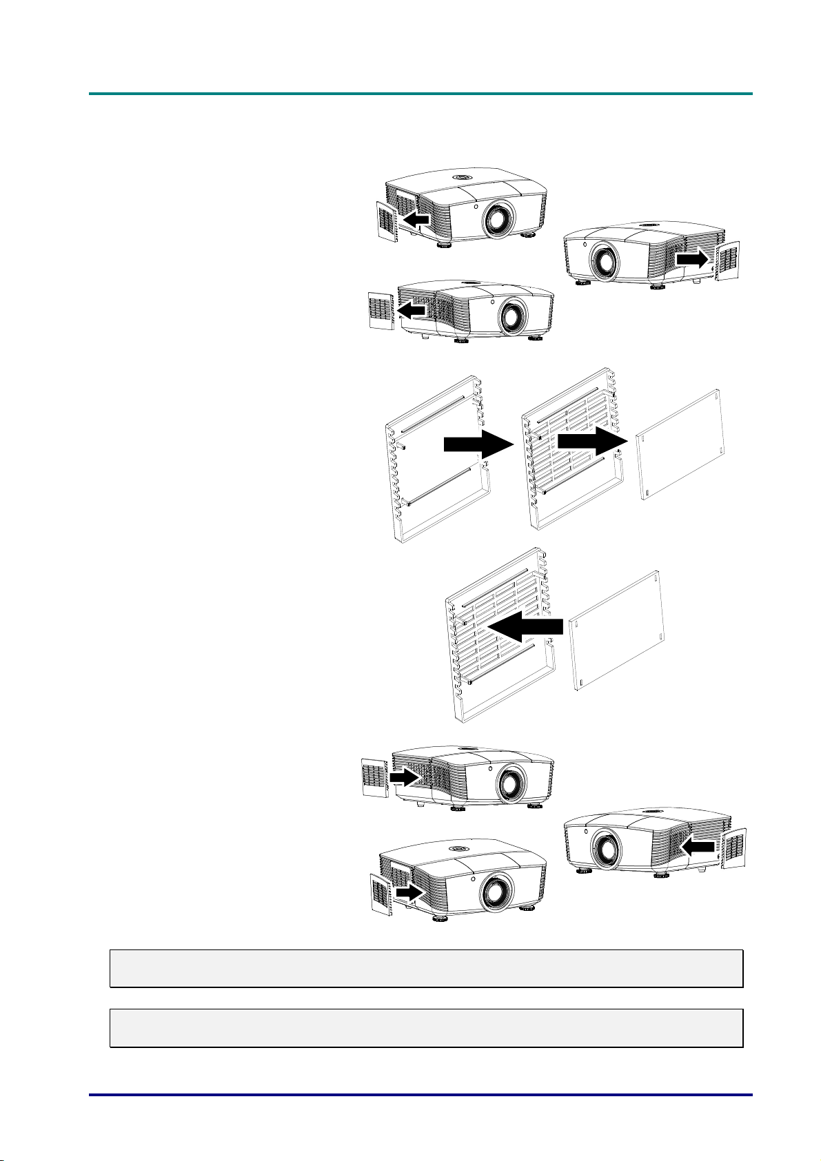
Replacing the Filter
Turn off the projector, and
1.
unplug the AC power cord
from the AC outlet.
Clean up the dust on the
projector and around the
air vents.
Pull out the filter cover and
remove from the projector
Lift the filter from the filter
2.
cover.
D
D
D
L
P
P
r
o
j
e
c
t
o
r
—
U
s
e
r
’
s
M
a
n
u
a
l
L
P
P
r
o
j
e
c
t
o
r
—
U
s
e
r
’
s
L
P
P
r
o
j
e
c
t
o
r
—
U
M
s
e
r
’
s
M
a
n
u
a
l
a
n
u
a
l
Replace a new filter
3.
module or replace filter into
cover.
Replace the filter cover
4.
back to the projector by
pushing gently in the
direction shown.
Warning:
Do not wash the filter with the water or other liquid matter
Important:
When the lamp is replaced, the filter should also be replaced, not cleaned.
– 59 –
Page 69
DLP Projector—User’s Manual
Cleaning the Projector
Cleaning the projector to remove dust and grime will help ensure trouble-free operation.
Warning:
1. Be sure to turn off and unplug the projector at least 30 minutes before cleaning. Failure to do
so could result in a severe burn.
2. Use only a dampened cloth when cleaning. Do not allow water to enter the ventilation
openings on the projector.
3. If a little water gets into the projector interior while cleaning, leave unplugged in a wellventilated room for several hours before using.
4. If a lot of water gets into the projector interior when cleaning, have the projector serviced.
Cleaning the Lens
You can purchase optic lens cleaner from most camera stores. Refer to the following to clean the
projector lens.
1. Apply a little optic lens cleaner to a clean soft cloth. (Do not apply the cleaner directly
to the lens.)
2. Lightly wipe the lens in a circular motion.
Caution:
1. Do not use abrasive cleaners or solvents.
2. To prevent discoloration or fading, avoid getting cleaner on the projector case.
Cleaning the Case
Refer to the following to clean the projector case.
1. Wipe off dust with a clean dampened cloth.
2. Moisten the cloth with warm water and mild detergent (such as used to wash dishes),
and then wipe the case.
3. Rinse all detergent from the cloth and wipe the projector again.
Caution:
To prevent discoloration or fading of the case, do not use abrasive alcohol-based cleaners.
— 60 —
Page 70
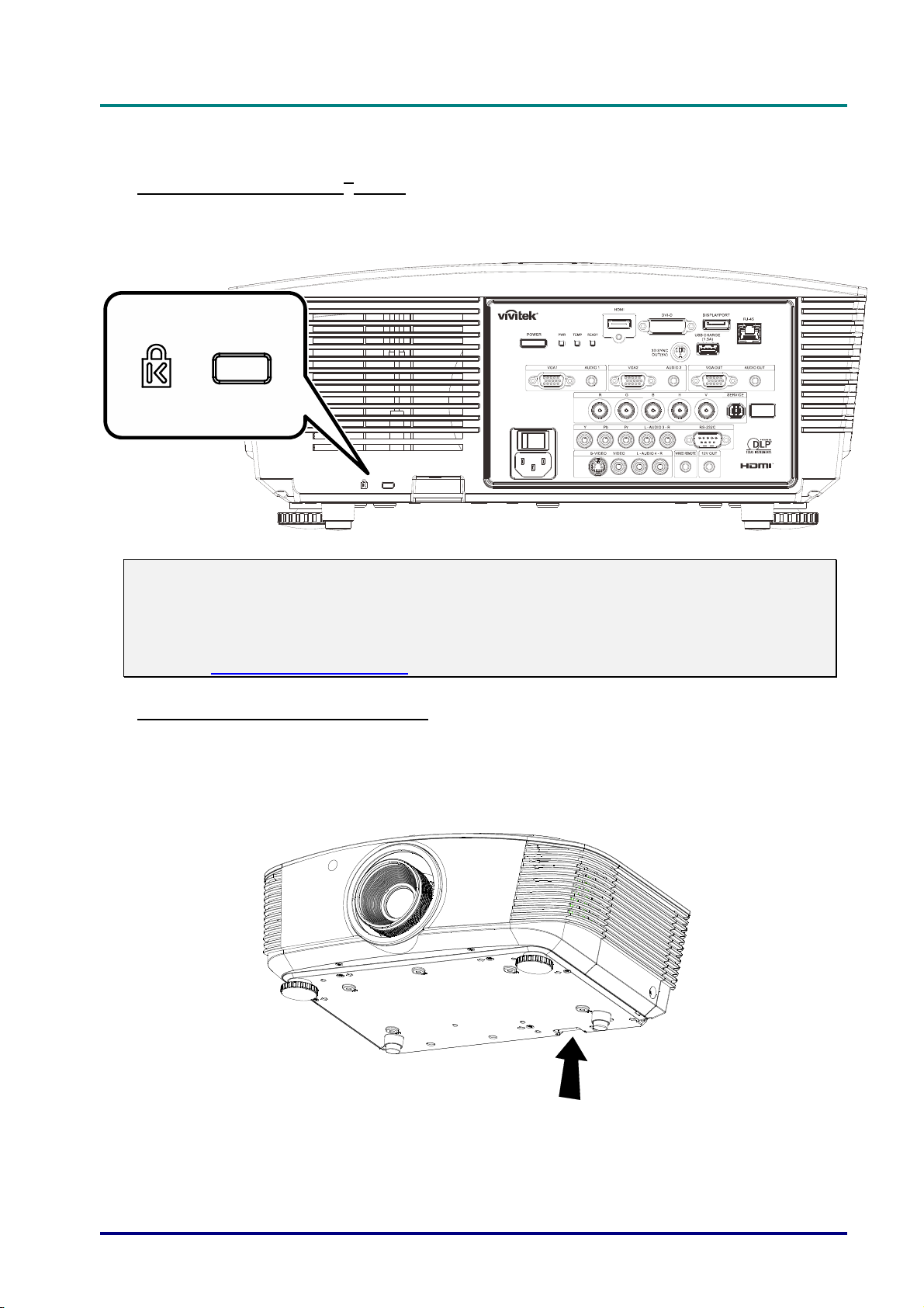
D
L
P
P
r
o
j
e
c
t
D
D
L
P
P
L
P
P
o
r
o
j
e
c
t
r
o
j
e
c
t
Using the Physical Lock
Using the Kensington® Lock
If you are concerned about security, attach the projector to a permanent object with the
Kensington slot and a security cable.
r
—
U
s
e
r
’
s
M
a
n
u
a
l
o
r
—
U
s
e
r
’
s
o
r
—
U
M
s
e
r
’
s
M
a
n
u
a
l
a
n
u
a
l
Note:
Contact your vendor for details on purchasing a suitable Kensington security cable.
The security lock corresponds to Kensington’s MicroSaver Security System. If you have any
comment, contact: Kensington, 2853 Campus Drive, San Mateo, CA 94403, U.S.A. Tel: 800535-4242, http://www.Kensington.com.
Using the Security Chain Lock
In addition to the password protection function and the Kensington lock, the Security Chain
Opening helps protect the PROJECTOR from unauthorized use.
See the following picture.
– 61 –
Page 71

DLP Projector—User’s Manual
TROUBLESHOOTING
Common problems and solutions
These guidelines provide tips to deal with problems you may encounter while using the projector.
If the problem remains unsolved, contact your dealer for assistance.
Often after time spent troubleshooting, the problem is traced to something as simple as a loose
connection. Check the following before proceeding to the problem-specific solutions.
• Use some other electrical device to confirm that the electrical outlet is working.
• Ensure the projector is turned on.
• Ensure all connections are securely attached.
• Ensure the attached device is turned on.
• Ensure a connected PC is not in suspending mode.
• Ensure a connected notebook computer is configured for an external display.
(This is usually done by pressing an Fn-key combination on the notebook.)
Tips for Troubleshooting
In each problem-specific section, try the steps in the order suggested. This may help you to solve
the problem more quickly.
Try to pin point the problem and thus avoid replacing non-defective parts.
For example, if you replace batteries and the problem remains, put the original batteries back and
go to the next step.
Keep a record of the steps you take when troubleshooting: The information may be useful when
calling for technical support or for passing on to service personnel.
— 62 —
Page 72

LED Error Messages
D
D
D
L
P
P
r
o
j
e
c
t
o
r
—
U
s
e
r
’
s
M
a
n
u
a
l
L
P
P
r
o
j
e
c
t
o
r
—
U
s
e
r
’
s
L
P
P
r
o
j
e
c
t
o
r
—
U
M
s
e
r
’
s
M
a
n
u
a
l
a
n
u
a
l
ERROR CODE MESSAGES
System Initial Flash
Ready to Power on (Standby) ON
System Power on Flash
Lamp Lit , System stable ON OFF ON
Cooling Flash
Over Temperature ON
Thermal Break Sensor error 4 blinks
Lamp Fail 5 blinks
Lamp Temperature shut down 5 blinks
Lamp Short circuit in output detected 5 blinks
Lamp End of lamp life detected 5 blinks
Lamp did not ignite 5 blinks
Lamp extinguished during normal operation 5 blinks
Lamp extinguished during run-up phase 5 blinks
Lamp voltage got error 5 blinks
Lamp ballast got error 5 blinks
Ballast watt value is out of range
(Lamp Normal & Eco mode)
Lamp ballast Communication error 5 blinks
Lamp ballast power error 5 blinks
Fan-1 error 6 blinks
Fan-2 error 6 blinks
Fan-3 error 6 blinks
Fan-4 error 6 blinks
Fan-5 error 6 blinks
Case Open 7 blinks
DAD1000 error 8 blinks
Color wheel error 9 blinks
In the event of an error, please disconnect the AC power cord and wait for one (1) minute before
restarting the projector. If the Power or Ready LEDs are still blinking or any other situation that isn't
listed in the chart above
, please contact your service center.
RED BLUE RED RED
5 blinks
-
-
-
-
-
-
-
-
-
-
-
-
-
-
-
-
-
-
-
-
-
-
-
-
-
-
OFF OFF
OFF OFF
OFF OFF
OFF OFF
ON OFF
OFF OFF
OFF ON
OFF 1 blinks
OFF 2 blinks
OFF 3 blinks
OFF 4 blinks
OFF 5 blinks
OFF 6 blinks
OFF 7 blinks
OFF 8 blinks
OFF 9 blinks
OFF 10 blinks
OFF 11 blinks
OFF 1 blinks
OFF 2 blinks
OFF 3 blinks
OFF 4 blinks
OFF 5 blinks
OFF OFF
OFF OFF
OFF OFF
POWER LED TEMP LED READY LED
Image Problems
Problem: No image appears on the screen
1. Verify the settings on your notebook or desktop PC.
2. Turn off all equipment and power up again in the correct order.
Problem: The image is blurred
1. Adjust the Focus on the projector.
2. Press the Auto button on the remote control.
3. Ensure the projector-to-screen distance is within the specified range.
4. Check that the projector lens is clean.
– 63 –
Page 73

DLP Projector—User’s Manual
Problem: The image is wider at the top or bottom (trapezoid effect)
1. Position the projector so it is as perpendicular to the screen as possible.
2. Use the Keystone button on the remote control to correct the problem.
Problem: The image is reversed
Check the Projection setting on the Settings 1 menu of the OSD.
Problem: The image is streaked
1. Set the Frequency and Tracking settings on the Image->Computer menu of the OSD to
the default settings.
2. To ensure the problem is not caused by a connected PC’s video card, connect to another
computer.
Problem: The image is flat with no contrast
Adjust the Contrast setting on the Image menu of the OSD.
Problem: The color of the projected image does not match the source image.
Adjust the Color Temperature and Gamma settings on the Image->Advanced menu of the
OSD.
Lamp Problems
Problem: There is no light from the projector
1. Check that the power cable is securely connected.
2. Ensure the power source is good by testing with another electrical device.
3. Restart the projector in the correct order and check that the Power LED is on.
4. If you have replaced the lamp recently, try resetting the lamp connections.
5. Replace the lamp module.
6. Put the old lamp back in the projector and have the projector serviced.
Problem: The lamp goes off
1. Power surges can cause the lamp to turn off. Re-plug power cord. When the Power LED is
on, press the power button.
2. Replace the lamp module.
3. Put the old lamp back in the projector and have the projector serviced.
Remote Control Problems
Problem: The projector does not respond to the remote control
1. Direct the remote control towards remote sensor on the projector.
2. Ensure the path between remote and sensor is not obstructed.
3. Turn off any fluorescent lights in the room.
4. Check the battery polarity.
5. Replace the battery.
6. Turn off other Infrared-enabled devices in the vicinity.
7. Have the remote control serviced.
— 64 —
Page 74

D
L
P
P
r
o
j
e
c
t
o
r
—
U
s
e
r
D
D
L
P
P
r
o
j
e
c
t
o
r
L
P
P
r
o
—
j
e
c
t
o
r
—
U
U
’
s
e
r
s
e
r
Audio Problems
Problem: There is no sound
1. Adjust the volume on the remote control.
2. Adjust the volume of the audio source.
3. Check the audio cable connection.
4. Test the source audio output with other speakers.
5. Have the projector serviced.
Problem: The sound is distorted
1. Check the audio cable connection.
2. Test the source audio output with other speakers.
3. Have the projector serviced.
Having the Projector Serviced
If you are unable to solve the problem, you should have the projector serviced. Pack the projector
in the original carton. Include a description of the problem and a checklist of the steps you took
when trying to fix the problem: The information may be useful to service personnel. For servicing,
return the projector to the place you purchased it.
s
M
a
n
u
a
l
’
s
M
’
s
M
a
n
u
a
l
a
n
u
a
l
– 65 –
Page 75

DLP Projector—User’s Manual
HDMI Q & A
Q. What is the difference between a “Standard” HDMI cable and a “High-Speed”
HDMI cable?
Recently, HDMI Licensing, LLC announced that cables would be tested as Standard or HighSpeed cables.
˙Standard (or “category 1”) HDMI cables have been tested to perform at speeds of 75Mhz or up
to 2.25Gbps, which is the equivalent of a 720p/1080i signal.
˙High Speed (or “category 2”) HDMI cables have been tested to perform at speeds of 340Mhz or
up to 10.2Gbps, which is the highest bandwidth currently available over an HDMI cable and
can successfully handle 1080p signals including those at increased color depths and/or
increased refresh rates from the Source. High-Speed cables are also able to accommodate
higher resolution displays, such as WQXGA cinema monitors (resolution of 2560 x 1600).
Q. How do I run HDMI cables longer than 10 meters?
There are many HDMI Adopters working on HDMI solutions that extend a cable’s effective
distance from the typical 10 meter range to much longer lengths. These companies manufacture
a variety of solutions that include active cables (active electronics built into cables that boost and
extend the cable’s signal), repeaters, amplifiers as well as CAT5/6 and fiber solutions.
Q. How can I tell if a cable is an HDMI certified cable?
All HDMI products are required to be certified by the manufacturer as part of the HDMI
Compliance Test Specification. However, there may be instances where cables bearing the
HDMI logo are available but have not been properly tested. HDMI Licensing, LLC actively
investigates these instances to ensure that the HDMI trademark is properly used in the market.
We recommend that consumers buy their cables from a reputable source and a company that is
trusted.
For more detail information check http://www.hdmi.org/learningcenter/faq.aspx#49
— 66 —
Page 76

D
L
P
P
r
o
j
e
c
t
o
r
—
U
s
e
r
’
s
M
a
D
D
L
P
P
r
o
j
e
c
t
o
r
—
U
s
e
L
P
P
r
o
j
e
c
t
o
r
—
U
r
s
e
r
n
’
s
M
a
n
’
s
M
a
n
SPECIFICATIONS
Specifications
Model D5010/D501ZAA/D501ZWAA D5110W D5380U
Display type
Resolution
Projection distance
Projection screen size
Projection lens
Throw ratio
Vertical keystone correction
Projection methods
Data compatibility
SDTV/EDTV/ HDTV
Video compatibility
H-Sync
V-Sync
Safety certification
Operation temperature
Dimensions
AC Input
Power consumption
Lamp
Audio speaker
Input Terminals
Output Terminals
Control Terminals
Security
NTSC (M, 3.58/4.43 MHz), PAL (B, D, G, H, I, M, N), SECAM (B, D, G, K, K1, L)
0.7" XGA DC3 0.65" WXGA DC2 0.67" WUXGA DC3 TypeA
1024x768 1280x800 1920x1200
1.5 meters ~ 7 meters
37.3” ~ 215” 34.3” ~ 200” 36” ~ 210”
Manual Focus/Manual Zoom
1.6 ~ 2.0 1.62 ~ 2.03 1.54 ~ 1.93
±40°
Front, Rear, Desktop/Ceiling (Rear, Front)
VGA, SVGA, XGA, SXGA, SXGA+, UXGA, WUXGA@60hz, Mac
480i, 576i, 480p, 576p, 720p, 1080i, 1080p
15, 31-91.4kHz
24~30Hz, 47 ~ 120Hz
FCC-B, cUL, UL, CE, C-tick, CCC, KC, CB, PCT
5° ~ 35°C
431.11mm (W) x 344.16mm (D) x 180.57mm (H)
AC Universal 100 – 240V
Typical 480W (boost) , <0.5watts(Stand By)/
Typical 365W(standard) , <0.5watts(Stand By)
370W (Normal) / 280W (Eco)
3W x 2
VGA x 2
DisplayPort x 1
DVI-D x 1
S-Video x 1
5 BNC (RGBHV) x 1
Component x 1
Composite video x 1
HDMI x 1
RCA stereo x 2
Mini-jack stereo x 2
VGA x 1
PC audio out x 1
RS-232C
RJ45
Screen trigger: DC Jack x 1 (DC12V 200mA output function)
wire remote
USB (type B) only for service/mouse control
USB (type A) only for power supply; WHDI
3D sync
Kensington lock
u
a
l
u
a
l
u
a
l
– 67 –
Page 77

DLP Projector—User’s Manual
(
)
Specifications
Model D5005 D5290U D5190HD
Display type
Resolution
Projection distance
Projection screen size
Projection lens
Throw ratio
Vertical keystone correction
Projection methods
Data compatibility
SDTV/EDTV/ HDTV
Video compatibility
H-Sync
V-Sync
Safety certification
Operation temperature
Dimensions
AC Input
Power consumption
Lamp
Audio speaker
Input Terminals
Output Terminals
Control Terminals
Security
0.7" XGA DC3 0.67" WUXGA DC3 TypeA 0.65” 1080P DC2 TypeA
1024x768 1920x1200 1920x1080
1.5 meters ~ 7 meters
37.3” ~ 215” 36” ~ 210” 35.1” ~ 205”
Manual Focus/Manual Zoom
1.6 ~ 2.0 1.54 ~ 1.93
±40°
Front, Rear, Desktop/Ceiling (Rear, Front)
VGA, SVGA, XGA, SXGA, SXGA+, UXGA, WUXGA@60hz, Mac
480i, 576i, 480p, 576p, 720p, 1080i, 1080p
NTSC (M, 3.58/4.43 MHz), PAL (B, D, G, H, I, M, N),
SECAM (B, D, G, K, K1, L)
15, 31-91.4kHz
24~30Hz, 47 ~ 120Hz
FCC-B, cUL, UL, CE, C-tick, CCC, KC, CB, PCT
5° ~ 35°C
431.11mm (W) x 344.16mm (D) x 180.57mm (H)
AC Universal 100 – 240V
Typical 420W (boost) <0.5watts(Stand By)/
Typical 365W(standard) <0.5watts(Stand By)
330W (Normal) / 280W (Eco)
3W x 2
VGA x 2
DisplayPort x 1
DVI-D x 1
S-Video x 1
5 BNC (RGBHV) x 1
Component x 1
Composite video x 1
HDMI x 1
RCA stereo x 2
Mini-jack stereo x 2
VGA x 1
PC audio out x 1
RS-232C
RJ45
Screen trigger: DC Jack x 1 (DC12V 200mA output function)
wire remote
USB (type B) only for service/mouse control
USB (type A) only for power supply; WHDI
3D sync
Kensington lock
370W (Normal) /
280W
Eco
— 68 —
Page 78
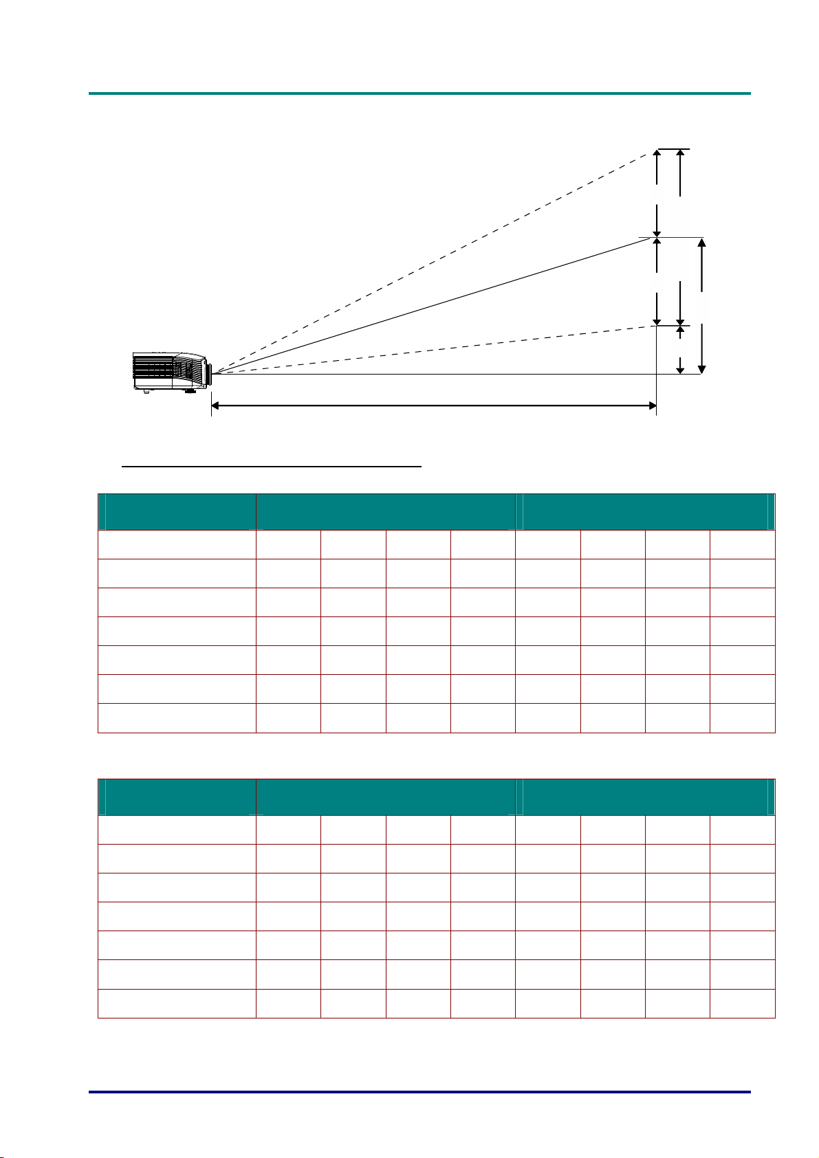
Projection Distance vs. Projection Size (WUXGA)
D
D
D
L
P
P
r
o
j
e
c
t
o
r
—
U
s
e
r
’
s
M
a
n
u
a
l
L
P
P
r
o
j
e
c
t
o
r
—
U
s
e
r
’
s
L
P
P
r
o
j
e
c
t
o
r
—
U
M
s
e
r
’
s
M
a
n
u
a
l
a
n
u
a
l
H
Image Hight
H
O
Projection Distance
V-Sync
Projection Distance and Size Table
Standard projection lens: TR: 1.54 ~ 1.93; offset=110%
TELE WIDE
Distance (m)
Diagonal (")
Image Width (mm)
Image Height (mm)
H (mm)
O (mm)
A (mm)
Long throw projection lens: TR: 1.93 ~ 2.9; offset=110%
1.66 3.33 4.16 8.31 1.66 3.32 6.63 9.95
40 80 100 200 50 100 200 300
862 1723 2154 4308 1077 2154 4308 6462
538 1077 1346 2692 673 1346 2692 4039
269 538 673 1346 337 673 1346 2019
296 592 740 1481 370 740 1481 2221
27 54 67 135 34 67 135 202
A
TELE WIDE
Distance (m)
Diagonal (")
Image Width (mm)
Image Height (mm)
H (mm)
O (mm)
A (mm)
2.5 6.25 12.49 18.74 2.08 6.24 12.47 18.71
40 100 200 300 50 150 300 450
862 2154 4308 6462 1077 3231 6462 9693
538 1346 2692 4039 673 2019 4039 6058
269 673 1346 2019 337 1010 2020 3029
296 740 1481 2221 370 1111 2222 3332
27 67 135 202 34 101 202 303
– 69 –
Page 79

DLP Projector—User’s Manual
Short throw projection lesn: TR: 0.77; offset=110%
FIX
Distance (m)
Diagonal (")
Image Width (mm)
Image Height (mm)
H (mm)
O (mm)
A (mm)
offset % = O/H × 100%
O=A+H
H=(1/2) × (image height)
0.66 1.33 1.66 2.49
40 80 100 150
862 1723 2154 3231
538 1077 1346 2019
269 538 673 1010
296 592 740 1111
27 54 67 101
— 70 —
Page 80
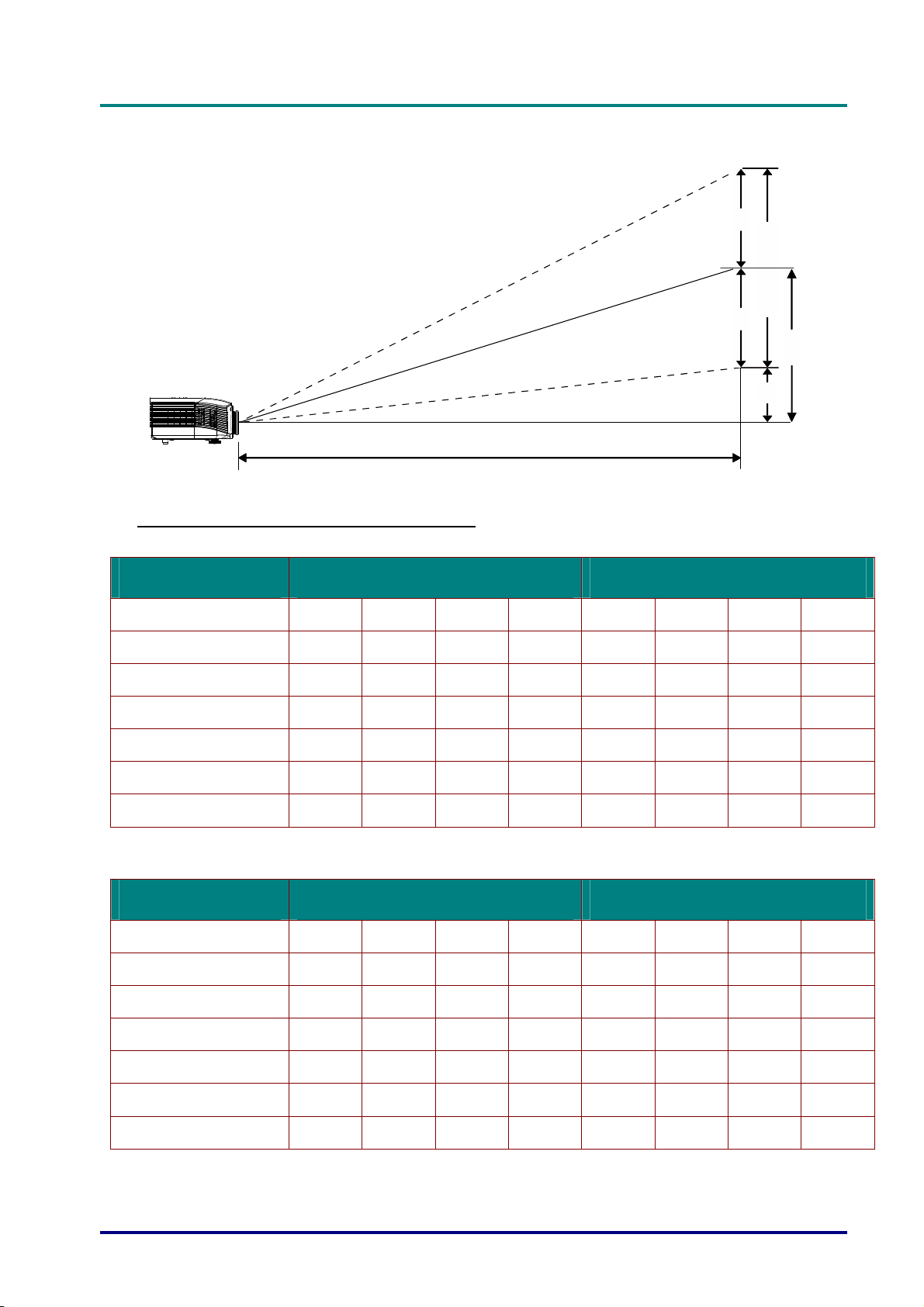
Projection Distance vs. Projection Size (WXGA)
D
D
D
L
P
P
r
o
j
e
c
t
o
r
—
U
s
e
r
’
s
M
a
n
u
a
l
L
P
P
r
o
j
e
c
t
o
r
—
U
s
e
r
’
s
L
P
P
r
o
j
e
c
t
o
r
—
U
M
s
e
r
’
s
M
a
n
u
a
l
a
n
u
a
l
H
Image Hight
H
O
Projection Distance
V-Sync
Projection Distance and Size Table
Standard projection lens: TR: 1.62 ~ 2.03; offset=110%
TELE WIDE
Distance (m)
Diagonal (")
Image Width (mm)
Image Height (mm)
H (mm)
O (mm)
A (mm)
Long throw projection lens: TR: 2.03 ~ 3.05; offset=110%
1.75 3.5 4.37 8.74 1.74 3.49 6.98 10.47
40 80 100 200 50 100 200 300
862 1723 2154 4308 1077 2154 4308 6462
538 1077 1346 2692 673 1346 2692 4039
269 538 673 1346 337 673 1346 2019
296 592 740 1481 370 740 1481 2221
27 54 67 135 34 67 135 202
A
TELE WIDE
Distance (m)
Diagonal (")
Image Width (mm)
Image Height (mm)
H (mm)
O (mm)
A (mm)
2.63 6.57 13.14 19.71 2.19 6.56 13.12 19.68
40 100 200 300 50 150 300 450
862 2154 4308 6462 1077 3231 6462 9693
538 1346 2692 4039 673 2019 4039 6058
269 673 1346 2019 337 1010 2019 3029
296 740 1481 2221 370 1111 2221 3332
27 67 135 202 34 101 202 303
– 71 –
Page 81

DLP Projector—User’s Manual
Short throw projection lens: TR: 0.81; offset=110%
FIX
Distance (m)
Diagonal (")
Image Width (mm)
Image Height (mm)
H (mm)
O (mm)
A (mm)
offset % = O/H × 100%
O=A+H
H=(1/2) × (image height)
0.7 1.4 1.74 2.62
40 80 100 150
862 1723 2154 3231
538 1077 1346 2019
269 538 673 1010
296 592 740 1111
27 54 67 101
— 72 —
Page 82
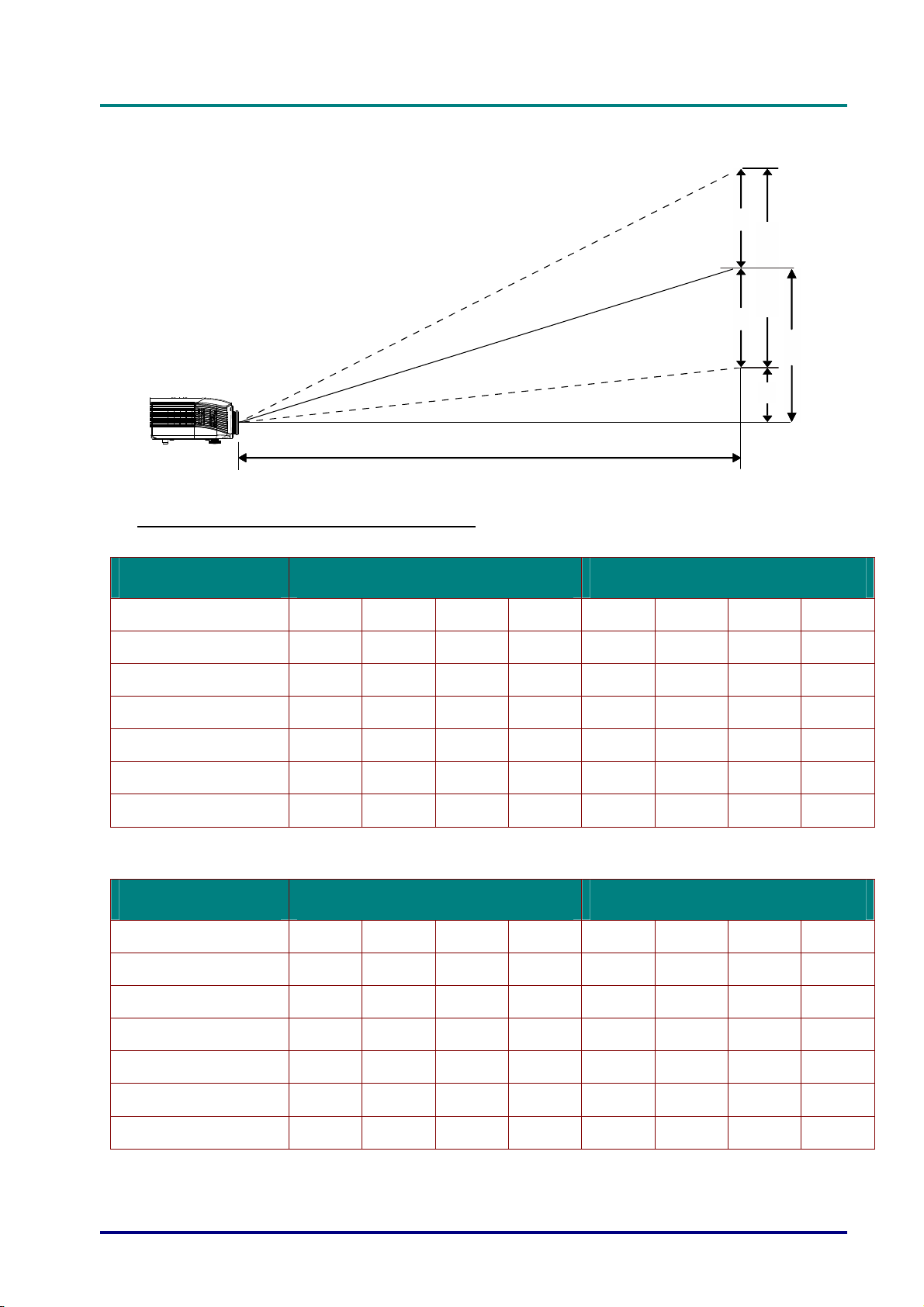
Projection Distance vs. Projection Size (XGA)
D
D
D
L
P
P
r
o
j
e
c
t
o
r
—
U
s
e
r
’
s
M
a
n
u
a
l
L
P
P
r
o
j
e
c
t
o
r
—
U
s
e
r
’
s
L
P
P
r
o
j
e
c
t
o
r
—
U
M
s
e
r
’
s
M
a
n
u
a
l
a
n
u
a
l
H
Image Hight
H
O
Projection Distance
V-Sync
Projection Distance and Size Table
Standard projection lens: TR: 1.6 ~ 2; offset=100%
TELE WIDE
Distance (m)
Diagonal (")
Image Width (mm)
Image Height (mm)
H (mm)
O (mm)
A (mm)
Long throw projection lens: TR: 2~ 3; offset=100%
1.63 3.25 4.06 8.13 1.63 3.25 6.50 9.75
40 80 100 200 50 100 200 300
813 1626 2032 4064 1016 2032 4064 6096
610 1219 1524 3048 762 1524 3048 4572
305 610 762 1524 381 762 1524 2286
305 610 762 1524 381 762 1524 2286
0 0 0 0 0 0 0 0
A
TELE WIDE
Distance (m)
Diagonal (")
Image Width (mm)
Image Height (mm)
H (mm)
O (mm)
A (mm)
2.44 6.10 12.19 18.29 2.03 6.10 12.19 18.29
40 100 200 300 50 150 300 450
813 2032 4064 6096 1016 3048 6096 9144
610 1524 3048 4572 762 2286 4572 6858
305 762 1524 2286 381 1143 2286 3429
305 762 1524 2286 381 1143 2286 3429
0 0 0 0 0 0 0 0
– 73 –
Page 83

DLP Projector—User’s Manual
Short throw projection lens: TR: 0.8; offset=100%
FIX
Distance (m)
Diagonal (")
Image Width (mm)
Image Height (mm)
H (mm)
O (mm)
A (mm)
offset % = O/H × 100%
O=A+H
H=(1/2) × (image height)
0.65 1.3 1.63 2.44
40 80 100 150
813 1626 2032 3048
610 1219 1524 2286
305 610 762 1143
305 610 762 1143
0 0 0 0
— 74 —
Page 84
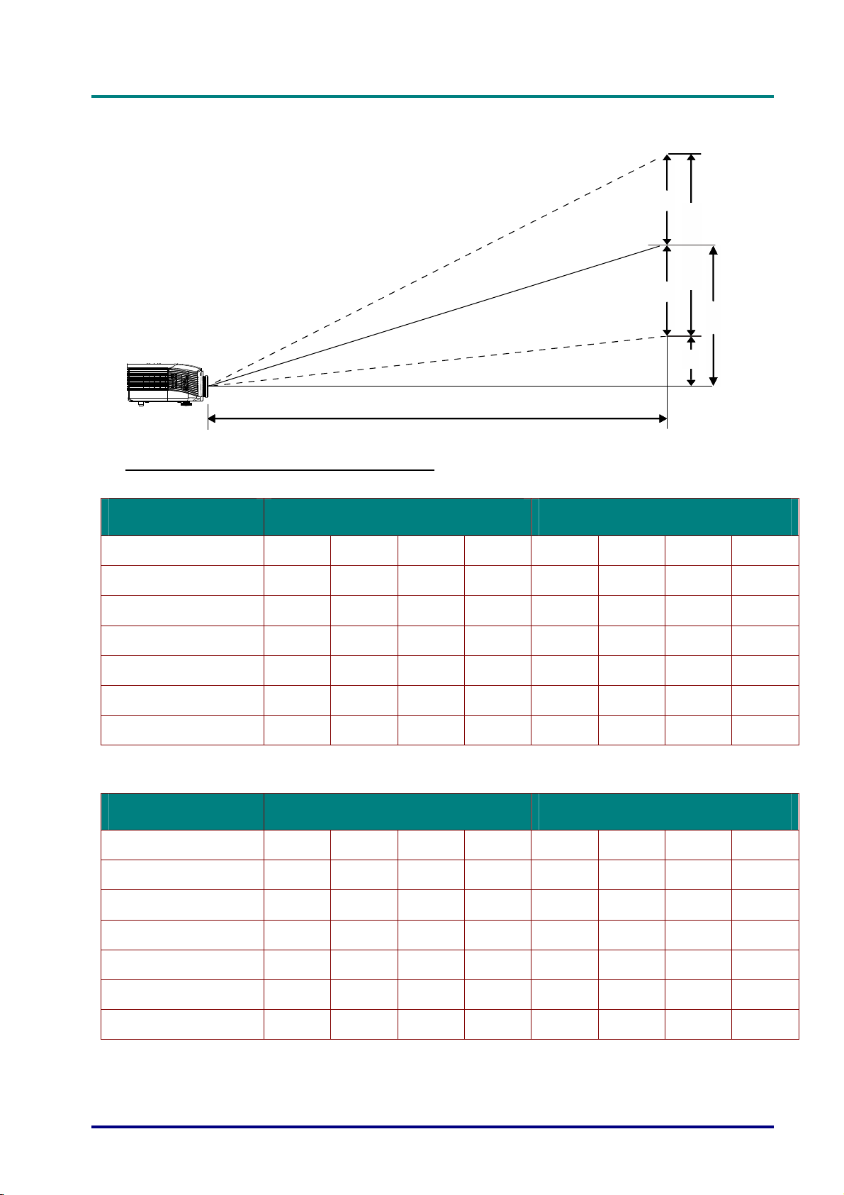
Projection Distance vs. Projection Size (1080P)
D
D
D
L
P
P
r
o
j
e
c
t
o
r
—
U
s
e
r
’
s
M
a
n
u
a
l
L
P
P
r
o
j
e
c
t
o
r
—
U
s
e
r
’
s
L
P
P
r
o
j
e
c
t
o
r
—
U
M
s
e
r
’
s
M
a
n
u
a
l
a
n
u
a
l
H
Image Hight
H
O
Projection Distance
V-Sync
Projection Distance and Size Table
Standard projection lens: TR: 1.54 ~ 1.93; offset=120%
TELE WIDE
Distance (m)
Diagonal (")
Image Width (mm)
Image Height (mm)
H (mm)
O (mm)
A (mm)
Long throw projection lens: TR: 1.93 ~ 2.9; offset=120%
1.71 3.42 4.27 8.55 1.70 3.41 6.82 10.23
40 80 100 200 50 100 200 300
886 1771 2214 4428 1107 2214 4428 6641
498 996 1245 2491 623 1245 2491 3736
249 498 623 1245 311 623 1245 1868
299 598 747 1494 374 747 1494 2241
50 100 125 249 62 125 249 374
A
TELE WIDE
Distance (m)
Diagonal (")
Image Width (mm)
Image Height (mm)
H (mm)
O (mm)
A (mm)
2.57 6.42 12.84 19.26 2.14 6.41 12.82 19.23
40 100 200 300 50 150 300 450
886 2214 4428 6641 1107 3321 6641 9962
498 1245 2491 3736 623 1868 3736 5604
249 623 1245 1868 311 934 1868 2802
299 747 1494 2241 374 1121 2241 3362
50 125 249 374 62 187 374 560
– 75 –
Page 85

DLP Projector—User’s Manual
Short throw projection lens: TR: 0.77; offset=120%
TELE
Distance (m)
Diagonal (")
Image Width (mm)
Image Height (mm)
H (mm)
O (mm)
A (mm)
offset % = O/H × 100%
O=A+H
H=(1/2) × (image height)
0.68 1.36 1.70 2.56
40 80 100 150
886 1771 2214 3321
498 996 1245 1868
249 498 623 934
299 598 747 1121
50 100 125 187
— 76 —
Page 86
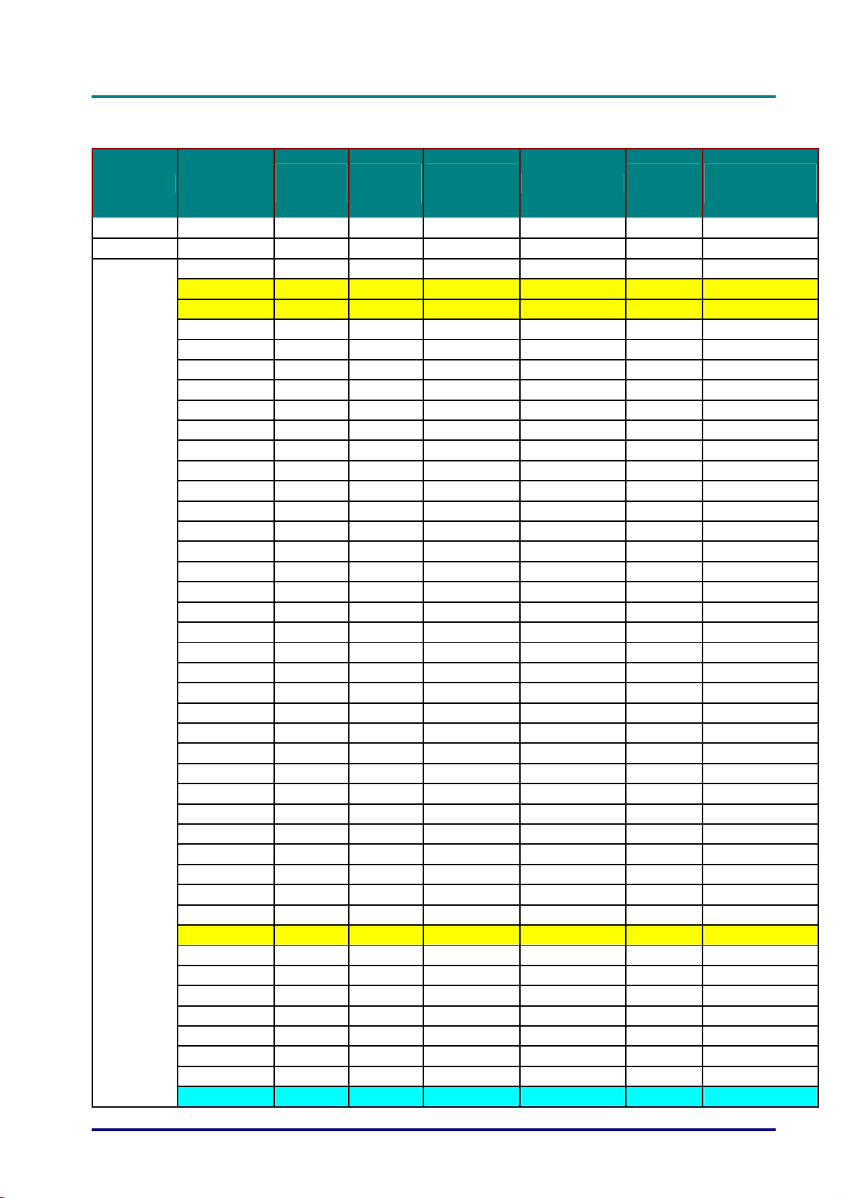
Timing Mode Table
D
D
D
L
P
P
r
o
j
e
c
t
o
r
—
U
s
e
r
’
s
M
a
n
u
a
l
L
P
P
r
o
j
e
c
t
o
r
—
U
s
e
r
’
s
L
P
P
r
o
j
e
c
t
o
r
—
U
M
s
e
r
’
s
M
a
n
u
a
l
a
n
u
a
l
Signal Resolution
NTSC
PAL/SECAM
VESA
-
-
640 x 400 37.9 85.1
720 x 400 31.5 70.1
720 x 400 37.9 85.0
640 x 480 31.5 60.0
640 x 480 37.9 72.8
640 x 480 37.5 75.0
640 x 480 43.3 85.0
800 x 600 35.2 56.3
800 x 600 37.9 60.3
800 x 600 46.9 75.0
800 x 600 48.1 72.2
800 x 600 53.7 85.1
800 x 600 76.3 120.0
1024 x 576 35.8 60.0
1024 x 600 37.3 60.0
1024 x 600 41.5 65.0
1024 x 768 48.4 60.0
1024 x 768 56.5 70.1
1024 x 768 60.0 75.0
1024 x 768 68.7 85.0
1024 x 768 97.6 120.0
1024 x 768 99.0 120.0
1152 x 864 67.5 75.0
1280 x 720 45.0 60.0
1280 x 720 90.0 120.0
1280 x 768 47.4 60.0
1280 x 768 47.8 59.9
1280 x 800 49.7 59.8
1280 x 800 62.8 74.9
1280 x 800 71.6 84.9
1280 x 800 101.6 119.9
1280 x 1024 64.0 60.0
1280 x 1024 80.0 75.0
1280 x 1024 91.1 85.0
1280 x 960 60.0 60.0
1280 x 960 85.9 85.0
1360 x 768 47.7 60.0
1400 x 1050 65.3 60.0
1440 x 900 55.5 59.9
1440 x 900 55.9 59.9
1440 x 900 70.6 75.0
1600 x1200 75.0 60.0
H-Sync
(KHz)
15.7 60.0 ○
15.6 50.0 ○
V-Sync
(Hz)
Composite
S-Video
- -
- -
- -
- -
- -
- -
- -
- -
- -
- -
- -
- -
- -
- -
- -
- -
- -
- -
- -
- -
- -
- -
- -
- -
- -
- -
- -
- -
- -
- -
- -
- -
- -
- -
- -
- -
- -
- -
- -
- -
- -
- -
Component
- - -
- - -
RGB
(Analog)
○ ○
○ ○
○ ○
○ ○
○ ○
○ ○
○ ○
○ ○
○ ○
○ ○
○ ○
○ ○
○ ○
○ ○
○ ○
○ ○
○ ○
○ ○
○ ○
○ ○
○ ○
○ ○
○ ○
○ ○
○ ○
○ ○
○ ○
○ ○
○ ○
○ ○
○ ○
○ ○
○ ○
○ ○
○ ○
○ ○
○ ○
○ ○
○ ○
○ ○
○ ○
○ ○
DP/DVI
HDMI (Digital)
– 77 –
Page 87
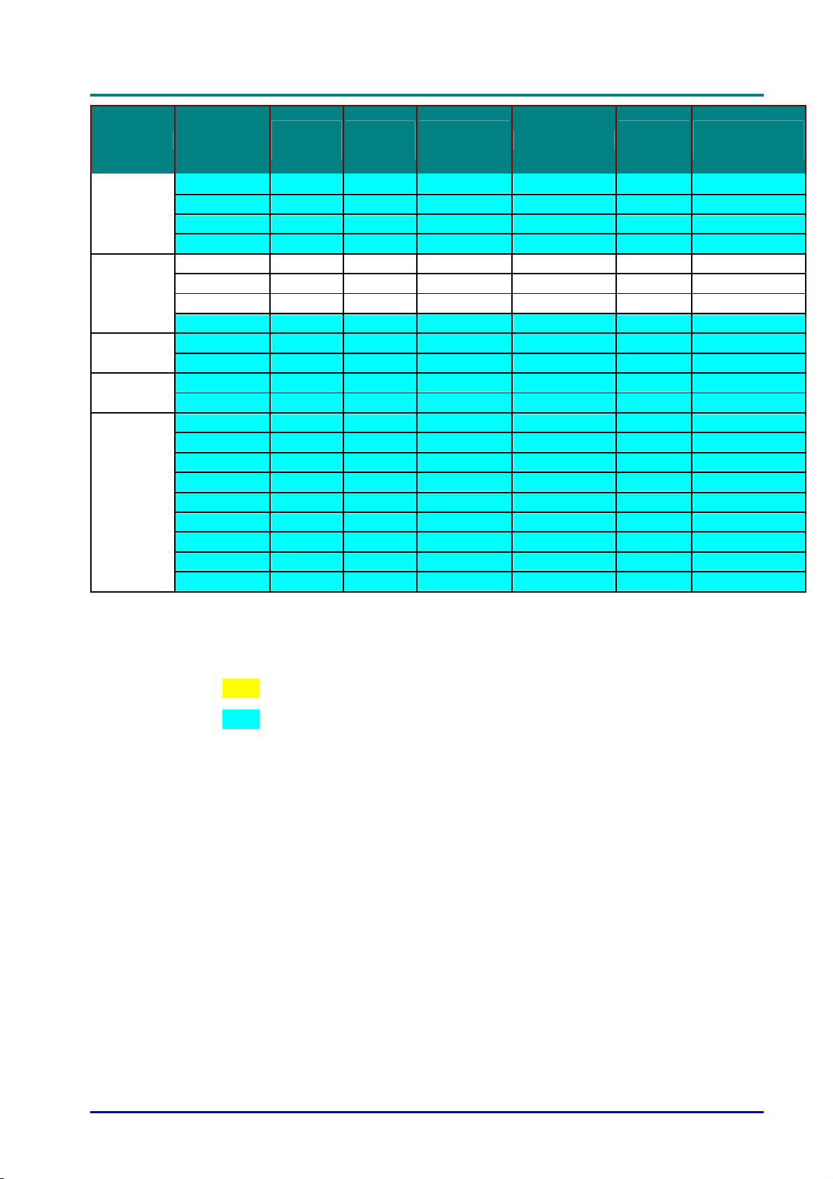
DLP Projector—User’s Manual
Signal Resolution
1680 x 1050 64.7 59.9
1680 x 1050 65.3 60.0
1920 x 1200 74.0 60.0
1920 x 1080 67.5 60.0
640 x 480 35.0 66.7
Apple
Macintosh
SDTV
EDTV
HDTV
832 x 624 49.7 74.5
1024 x 768 60.2 74.9
1152 x 870 68.7 75.1
480i 15.7 60.0
576i 15.6 50.0
576p 31.3 50.0
480p 31.5 60.0
720p 37.5 50.0
720p 45.0 60.0
1080i 33.8 60.0
1080i 28.1 50.0
1080p 27.0 24.0
1080p 28.0 25.0
1080p 33.7 30.0
1080p 56.3 50.0
1080p 67.5 60.0
H-Sync
(KHz)
V-Sync
(Hz)
Composite
S-Video
- -
- -
- -
- -
- -
- -
- -
- -
-
-
-
-
-
-
-
-
-
-
-
-
-
Component
○
○
○
○
○
○
○
○
○
○
○
○
○
RGB
(Analog)
○ ○
○ ○
○ ○
○ ○
○ ○
○ ○
○ ○
○ ○
-
-
-
-
-
-
-
-
-
-
-
-
-
DP/DVI
HDMI (Digital)
○
○
○
○
○
○
○
○
○
○
○
○
○
O: Frequency supported
—: Frequency not supported
Resolution others than native resolution may be display with uneven size of text or line.
★ The color of mean Displayable only. (4:3 only)
★ The color of mean may have a little noise is acceptable, Because video mode sync don’t
auto adjustment.
★ HDTV timing main check tool is DVD player, VG828 is secondary.
— 78 —
Page 88
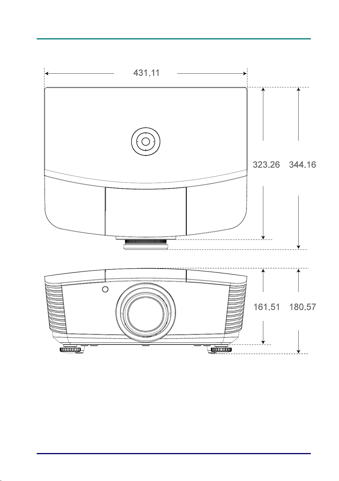
Projector Dimensions
D
D
D
L
P
P
r
o
j
e
c
t
o
r
—
U
s
e
r
’
s
M
a
n
u
a
l
L
P
P
r
o
j
e
c
t
o
r
—
U
s
e
r
’
s
L
P
P
r
o
j
e
c
t
o
r
—
U
M
s
e
r
’
s
M
a
n
u
a
l
a
n
u
a
l
– 79 –
Page 89

DLP Projector—User’s Manual
REGULATORY COMPLIANCE
FCC Warning
This equipment has been tested and found to comply with the limits for a Class B digital device
pursuant to Part 15 of the FCC Rules. These limits are designed to provide reasonable protection
against harmful interference when the equipment is operated in a commercial environment.
This equipment generates, uses, and can radiate radio frequency energy and, if not installed and
used in accordance with the instruction manual, may cause harmful interference to radio
communications. Operation of this equipment in a residential area is likely to cause harmful
interference in which case the user will be required to correct the interference at his/her own
expense.
Changes or modifications not expressly approved by the parties responsible for compliance could
void the user’s authority to operate the equipment.
Canada
This class B digital apparatus complies with Canadian ICES-003.
Safety Certifications
FCC-B, cUL, UL, CE, C-tick, CCC, KC, CB, PCT
— 80 —
Page 90
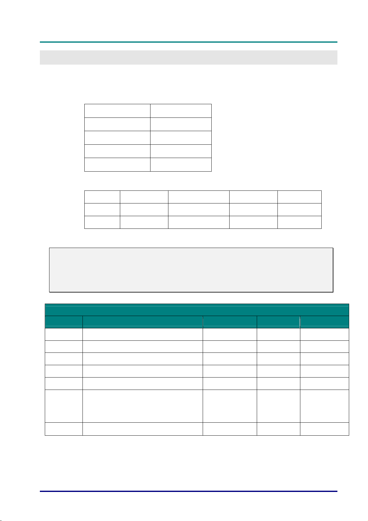
RS-232C Protocol
RS232 Setting
D
D
D
L
P
P
r
o
j
e
c
t
o
r
—
U
s
e
r
’
s
M
a
n
u
a
l
L
P
P
r
o
j
e
c
t
o
r
—
U
s
e
r
’
s
L
P
P
r
o
j
e
c
t
o
r
—
U
M
s
e
r
’
s
M
a
n
u
a
l
a
n
u
a
l
APPENDIX I
Baud rate:
Parity check: None
Data bit: 8
Stop bit: 1
Flow Control None
Control Command Structure
Header code Command code Data code End code
HEX Command Data 0Dh
ASCII ‘V’ Command Data CR
Operation Command
Note:
XX=00-98, projector's ID, XX=99 is for all projectors
Return Result P=Pass / F=Fail
n: 0:Disable/1: Enable/Vaule(0~9999)
9600
Command Group 00
ASCII HEX Function Description Return Result
VXXS0001 56h Xh Xh 53h 30h 30h 30h 31h 0Dh Power On P/F
VXXS0002 56h Xh Xh 53h 30h 30h 30h 32h 0Dh Power Off P/F
VXXS0003 56h Xh Xh 53h 30h 30h 30h 33h 0Dh Resync P/F
VXXG0004 56h Xh Xh 47h 30h 30h 30h 34h 0Dh Get Lamp Hours Pn/F
VXXS0006 56h Xh Xh 53h 30h 30h 30h 36h 0Dh System Reset P/F
0:Reset
VXXG0007 56h Xh Xh 47h 30h 30h 30h 37h 0Dh Get System Status
VXXG0008 56h Xh Xh 47h 30h 30h 30h 38h 0Dh Get F/W Version Pn/F
1:Standby
2:Operation
3:Cooling
Pn/F
– 81 –
Page 91
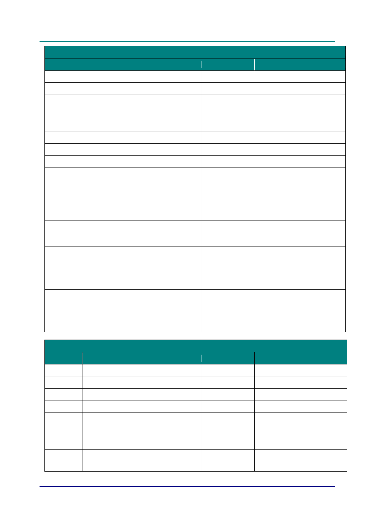
DLP Projector—User’s Manual
Command Group 01
ASCII HEX Function Description Return Value
VXXG0101 56h Xh Xh 47h 30h 31h 30h 31h 0Dh Get Brightness n=0~100 Pn/F
VXXS0101n 56h Xh Xh 53h 30h 31h 30h 31h nh 0Dh Set Brightness n=0~100 P/F
VXXG0102 56h Xh Xh 47h 30h 31h 30h 32h 0Dh Get Contrast n=0~100 Pn/F
VXXS0102n 56h Xh Xh 53h 30h 31h 30h 32h nh 0Dh Set Contrast n=0~100 P/F
VXXG0103 56h Xh Xh 47h 30h 31h 30h 33h 0Dh Get Color n=0~100 Pn/F
VXXS0103n 56h Xh Xh 53h 30h 31h 30h 33h nh 0Dh Set Color n=0~100 P/F
VXXG0104 56h Xh Xh 47h 30h 31h 30h 34h 0Dh Get Tint n=0~100 Pn/F
VXXS0104n 56h Xh Xh 53h 30h 31h 30h 34h nh 0Dh Set Tint n=0~100 P/F
VXXG0105 56h Xh Xh 47h 30h 31h 30h 35h 0Dh Get Sharpness 0~31 Pn/F
VXXS0105n 56h Xh Xh 53h 30h 31h 30h 35h nh 0Dh Set Sharpness 0~31 P/F
VXXG0106 56h Xh Xh 47h 30h 31h 30h 36h 0Dh
VXXS0106n 56h Xh Xh 53h 30h 31h 30h 36h nh 0Dh
VXXG0107 56h Xh Xh 47h 30h 31h 30h 37h 0Dh Get Gamma
VXXS0107n 56h Xh Xh 53h 30h 31h 30h 37h nh 0Dh Set Gamma
Get Color
Temperature
Set Color
Temperature
0:Warm
1:Normal
2:Cold
0:Warm
1:Normal
2:Cold
0:1.8
1:2.0
2:2.2
3:2.4
4:B&W
5:Linear
0:1.8
1:2.0
2:2.2
3:2.4
4:B&W
5:Linear
Pn/F
P/F
Pn/F
P/F
Command Group 02
ASCII HEX Function Description Return Value
VXXS0201 56h Xh Xh 53h 30h 32h 30h 31h 0Dh Select RGB P/F
VXXS0202 56h Xh Xh 53h 30h 32h 30h 32h 0Dh Select RGB2 P/F
VXXS0203 56h Xh Xh 53h 30h 32h 30h 33h 0Dh Select DVI P/F
VXXS0204 56h Xh Xh 53h 30h 32h 30h 34h 0Dh Select Video P/F
VXXS0205 56h Xh Xh 53h 30h 32h 30h 35h 0Dh Select S-Video P/F
VXXS0206 56h Xh Xh 53h 30h 32h 30h 36h 0Dh Select HDMI P/F
VXXS0207 56h Xh Xh 53h 30h 32h 30h 37h 0Dh Select BNC P/F
VXXS0208 56h Xh Xh 53h 30h 32h 30h 38h 0Dh
— 82 —
Select
Component
P/F
Page 92
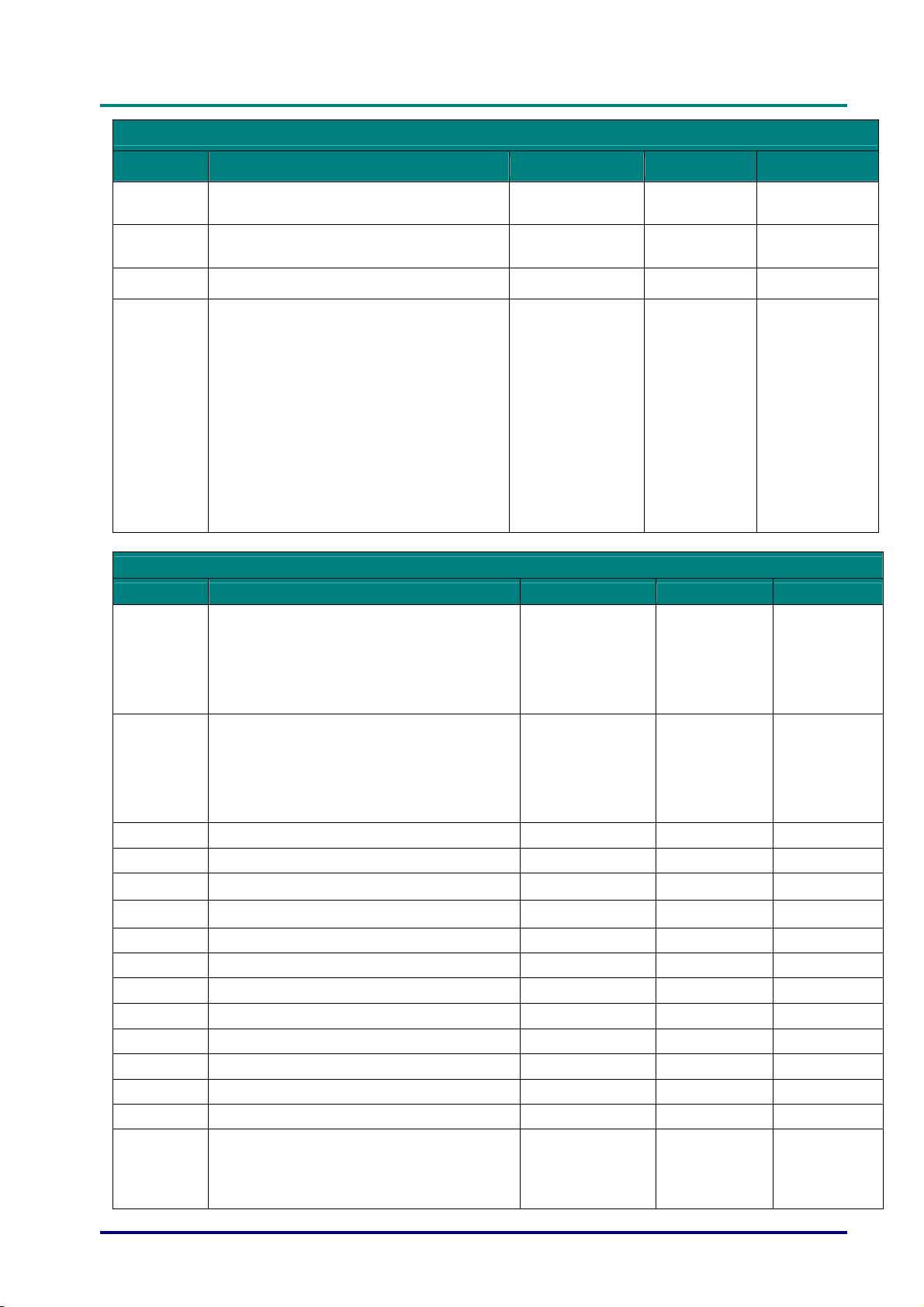
D
L
P
P
r
o
j
e
c
t
o
r
—
U
s
e
r
’
s
M
a
n
u
a
l
D
L
P
P
r
o
j
e
c
t
o
r
—
U
s
e
r
’
s
D
L
P
P
r
o
j
e
c
t
o
r
—
U
Command Group 02
ASCII HEX Function Description Return Value
M
s
e
r
’
s
M
a
n
u
a
l
a
n
u
a
l
VXXS0209 56h Xh Xh 53h 30h 32h 30h 39h 0Dh
VXXS0210 56h Xh Xh 53h 30h 32h 31h 30h 0Dh
VXXS0211 56h Xh Xh 53h 30h 32h 31h 31h 0Dh Select Multi Media P/F
VXXG0220 56h Xh Xh 47h 30h 32h 32h 30h 0Dh
Command Group 03
ASCII HEX Function Description Return Value
VXXG0301 56h Xh Xh 47h 30h 33h 30h 31h 0Dh Get Scaling
VXXS0301n 56h Xh Xh 53h 30h 33h 30h 31h nh 0Dh Set Scaling
VXXG0302 56h Xh Xh 47h 30h 33h 30h 32h 0Dh Blank Pn/F
VXXS0302n 56h Xh Xh 53h 30h 33h 30h 32h nh 0Dh Blank P/F
VXXG0303 56h Xh Xh 47h 30h 33h 30h 33h 0Dh Auto Keystone On Pn/F
Select HDMI 2
(MEDIA)
Select
Display Port
Get Current
Source
P/F
P/F
Return
1:RGB
2:RGB2
3:DVI
4:Video
5:S-Video
6:HDMI 1
7:BNC
8:Component
9:HDMI 2
10:Display Port
11:Multi Media.
0:Fill
1:4:3
2:16:9
3:Letter Box
4:Native
5:2.35:1
0:Fill
1:4:3
2:16:9
3:Letter Box
4:Native
5:2.35:1
Pn/F
Pn/F
P/F
VXXS0303n 56h Xh Xh 53h 30h 33h 30h 33h nh 0Dh Auto Keystone On P/F
VXXG0304 56h Xh Xh 47h 30h 33h 30h 34h 0Dh Freeze On Pn/F
VXXS0304n 56h Xh Xh 53h 30h 33h 30h 34h nh 0Dh Freeze On P/F
VXXG0305 56h Xh Xh 47h 30h 33h 30h 35h 0Dh Volume n=0~10 Pn/F
VXXS0305n 56h Xh Xh 53h 30h 33h 30h 35h nh 0Dh Volume n=0~10 P/F
VXXG0306 56h Xh Xh 47h 30h 33h 30h 36h 0Dh Treble n=0~16 Pn/F
VXXS0306n 56h Xh Xh 53h 30h 33h 30h 36h nh 0Dh Treble n=0~16 P/F
VXXG0307 56h Xh Xh 47h 30h 33h 30h 37h 0Dh Bass n=0~16 Pn/F
VXXS0307n 56h Xh Xh 53h 30h 33h 30h 37h nh 0Dh Bass n=0~16 P/F
0:Front
VXXG0308 56h Xh Xh 47h 30h 33h 30h 38h 0Dh Projection Mode
– 83 –
1:Rear
2:Ceiling
3:Rear+Ceiling
Pn/F
Page 93

DLP Projector—User’s Manual
Command Group 03
ASCII HEX Function Description Return Value
0:Front
VXXS0308n 56h Xh Xh 53h 30h 33h 30h 38h nh 0Dh Projection Mode
VXXG0309 56h Xh Xh 47h 30h 33h 30h 39h 0Dh
VXXS0309n 56h Xh Xh 53h 30h 33h 30h 39h nh 0Dh
VXXG0310 56h Xh Xh 47h 30h 33h 31h 30h 0Dh
VXXS0310n 56h Xh Xh 53h 30h 33h 31h 30h nh 0Dh
VXXG0311 56h Xh Xh 47h 30h 33h 31h 31h 0Dh Adjust the zoom n=-10~+10 Pn/F
VXXS0311n 56h Xh Xh 53h 30h 33h 31h 31h nh 0Dh Adjust the zoom n=-10~+10 P/F
VXXG0312 56h Xh Xh 47h 30h 33h 31h 32h 0Dh Adjust the focus n=-20~+20 Pn/F
VXXS0312n 56h Xh Xh 53h 30h 33h 31h 32h nh 0Dh Adjust the focus n=-20~+20 P/F
VXXG0313 56h Xh Xh 47h 30h 33h 31h 33h 0Dh
VXXS0313n 56h Xh Xh 53h 30h 33h 31h 33h nh 0Dh
VXXG0314 56h Xh Xh 47h 30h 33h 31h 34h 0Dh
VXXS0314n 56h Xh Xh 53h 30h 33h 31h 34h nh 0Dh
VXXG0315 56h Xh Xh 47h 30h 33h 31h 35h 0Dh 3D
VXXS0315n 56h Xh Xh 53h 30h 33h 31h 35h nh 0Dh 3D
VXXG0316 56h Xh Xh 47h 30h 33h 31h 36h 0Dh 3D Sync Invert
VXXS0316n 56h Xh Xh 53h 30h 33h 31h 36h nh 0Dh 3D Sync Invert
VXXG0317 56h Xh Xh 47h 30h 33h 31h 37h 0Dh 3D Format
VXXS0317n 56h Xh Xh 53h 30h 33h 31h 37h nh 0Dh 3D Format
VXXG0318 56h Xh Xh 47h 30h 33h 31h 38h 0Dh Tilt Angle Warning
VXXS0318 56h Xh Xh 53h 30h 33h 31h 38h nh 0Dh Tilt Angle Warning
Set vertical
keystone value
Set vertical
keystone value
Set horizontal
keystone value
Set horizontal
keystone value
Adjust the vertical
lens shift
Adjust the vertical
lens shift
Adjust the
horizontal lens shift
Adjust the
horizontal lens shift
1:Rear
2:Ceiling
3:Rear+Ceiling
n=-40~+40 Pn/F
n=-40~+40 P/F
n=-20~+20 Pn/F
n=-20~+20 P/F
n=-20~+20 Pn/F
n=-20~+20 P/F
n=-20~+20 Pn/F
n=-20~+20 P/F
0:Off
1:DLP-Link
2:IR
0:Off
1:DLP-Link
2:IR
0:Off
1:On
0:Off
1:On
0:Frame
Sequential
1:Top/Bottom
2:Side-By-Side
3:Frame
Packing
0:Frame
Sequential
1:Top/Bottom
2:Side-By-Side
3:Frame
Packing
0:Off
1:On
0:Off
1:On
P/F
Pn/F
P/F
Pn/F
P/F
Pn/F
P/F
Pn/F
P/F
— 84 —
Page 94

D
L
P
P
r
o
j
e
c
t
o
r
—
U
s
e
r
’
s
M
a
n
u
a
l
D
L
P
P
r
o
j
e
c
t
o
r
—
U
s
e
r
’
s
D
L
P
P
r
o
j
e
c
t
o
r
—
U
Command Group 04 (Remote Control)
ASCII HEX Function Description Return Value
VXXS0401 56h Xh Xh 53h 30h 34h 30h 31h 0Dh UP arrow P/F
VXXS0402 56h Xh Xh 53h 30h 34h 30h 32h 0Dh DOWN arrow P/F
VXXS0403 56h Xh Xh 53h 30h 34h 30h 33h 0Dh LEFT arrow P/F
VXXS0404 56h Xh Xh 53h 30h 34h 30h 34h 0Dh RIGHT arrow P/F
VXXS0405 56h Xh Xh 53h 30h 34h 30h 35h 0Dh POWER P/F
VXXS0406 56h Xh Xh 53h 30h 34h 30h 36h 0Dh EXIT P/F
VXXS0407 56h Xh Xh 53h 30h 34h 30h 37h 0Dh INPUT P/F
VXXS0408 56h Xh Xh 53h 30h 34h 30h 38h 0Dh AUTO P/F
VXXS0409 56h Xh Xh 53h 30h 34h 30h 39h 0Dh KEYSTONE+ P/F
VXXS0410 56h Xh Xh 53h 30h 34h 31h 30h 0Dh KEYSTONE- P/F
VXXS0411 56h Xh Xh 53h 30h 34h 31h 31h 0Dh MENU P/F
VXXS0412 56h Xh Xh 53h 30h 34h 31h 32h 0Dh STATUS P/F
M
s
e
r
’
s
M
a
n
u
a
l
a
n
u
a
l
VXXS0413 56h Xh Xh 53h 30h 34h 31h 33h 0Dh MUTE P/F
VXXS0414 56h Xh Xh 53h 30h 34h 31h 34h 0Dh ZOOM+ P/F
VXXS0415 56h Xh Xh 53h 30h 34h 31h 35h 0Dh ZOOM- P/F
VXXS0416 56h Xh Xh 53h 30h 34h 31h 36h 0Dh BLANK P/F
VXXS0417 56h Xh Xh 53h 30h 34h 31h 37h 0Dh FREEZE P/F
VXXS0418 56h Xh Xh 53h 30h 34h 31h 38h 0Dh VOLUME+ P/F
VXXS0419 56h Xh Xh 53h 30h 34h 31h 39h 0Dh VOLUME- P/F
VXXS0420 56h Xh Xh 53h 30h 34h 32h 30h 0Dh Enter P/F
– 85 –
 Loading...