

Vivitek D5110W-WNL, D5010-WNL User manual

Copyright
This publication, including all photographs, illustrations and software, is protected under international
copyright laws, with all rights reserved. Neither this manual, nor any of the material contained herein, may
be reproduced without written consent of the author.
© Copyright 2013
Disclaimer
The information in this document is subject to change without notice. The manufacturer makes no
representations or warranties with respect to the contents hereof and specifically disclaims any implied
warranties of merchantability or fitness for any particular purpose. The manufacturer reserves the right to
revise this publication and to make changes from time to time in the content hereof without obligation of
the manufacturer to notify any person of such revision or changes.
Trademark Recognition
Kensington is a U.S. registered trademark of ACCO Brand Corporation with issued registrations
and pending applications in other countries throughout the world.
HDMI, the HDMI Logo, and High-Definition Multimedia Interface are trademarks or
registered trademarks of HDMI Licensing LLC in the United States and other countries.
All other product names used in this manual are the properties of their respective owners and are
acknowledged.
— i —
DLP Projector—User’s Manual
Important Safety Information
Important:
It is strongly recommended that you read this section carefully before using the projector. These
safety and usage instructions will ensure that you enjoy many years of safe use of the projector.
Keep this manual for future reference.
Symbols Used
Warning symbols are used on the unit and in this manual to alert you of hazardous situations.
The following styles are used in this manual to alert you to important information.
Note:
Provides additional information on the topic at hand.
Important:
Provides additional information that should not be overlooked.
Caution:
Alerts you to situations that may damage the unit.
Warning:
Alerts you to situations that may damage the unit, create a hazardous environment, or cause
personal injury.
Throughout this manual, component parts and items in the OSD menus are denoted in bold font as in this
example:
“Push the Menu button on the remote control to open the Main menu.”
General Safety Information
¾ Do not open the unit case. Aside from the projection lamp, there are no user-serviceable parts in
the unit. For servicing, contact qualified service personnel.
¾ Follow all warnings and cautions in this manual and on the unit case.
¾ The projection lamp is extremely bright by design. To avoid damage to eyes, do not look into the
lens when the lamp is on.
¾ Do not place the unit on an unstable surface, cart, or stand.
¾ Avoid using the system near water, in direct sunlight, or near a heating device.
¾ Do not place heavy objects such as books or bags on the unit.
— ii —
Projector Installation Notice
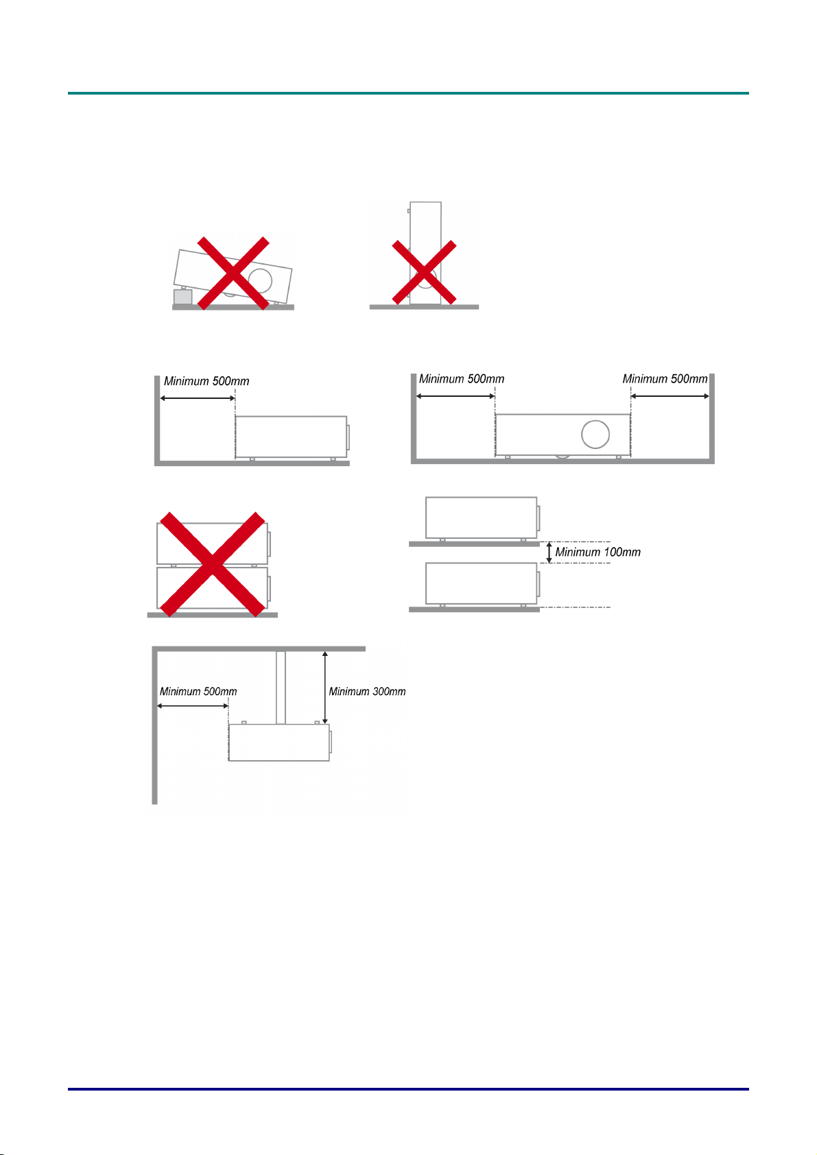
¾ Place the projector in a horizontal position
The tilt angle of the projector please see Tilt Up/Down caution on page 52.
P
r
e
f
a
c
e
P
r
P
r
e
f
a
c
e
e
f
a
c
e
¾ Allow at least 50 cm clearance around the exhaust vent.
¾ Ensure that the intake vents do not recycle hot air from the exhaust vent.
¾ When operating the projector in an enclosed space, ensure that the surrounding air temperature
within the enclosure does not exceed operation temperature while the projector is running, and the
air intake and exhaust vents are unobstructed.
¾ All enclosures should pass a certified thermal evaluation to ensure that the projector does not
recycle exhaust air, as this may cause the device to shutdown even if the enclosure temperature is
with the acceptable operation temperature range.
– iii –

DLP Projector—User’s Manual
Verify Installation Location
¾ To supply power, the 3-blade (with earthing lead) socket should be used to ensure proper
grounding and equalized ground potential for all of the equipment in the Projector System.
¾ The power code provided with the Projector should be used. In case of any missing item, other
qualified 3-blade (with earthing lead) power cord can be used as substitution; however, do not use
2-blade power cord.
¾ Verify if the voltage is stable, grounded properly and there is no electricity leakage.
¾ Measure total power consumption which should not higher the safety capacity and avoid safety
issue and short circuit.
¾ Turn on Altitude Mode when located in high altitude areas
¾ When installation the bracket, make sure the weight limit is not exceed and firmly secured.
¾ Avoid installing near air conditioner duct or subwoofer.
¾ Avoid installing at high temperature, insufficient cooling and heavy dust locations.
¾ Keep your product away from fluorescent lamps to avoid malfunction
caused by IR interference
¾ The VGA IN connector should be connected to the VGA IN port. Note that it should be inserted
tightly, with the screws on both sides securely fastened to ensure proper connection of the signal
wire for achieving optimal display effect.
¾ The AUDIO IN connector should be connected to the AUDIO IN port and CANNOT be connected
to AUDIO OUT or other ports like BNC, RCA; otherwise, it will lead to mute output and even
DAMAGE the port.
¾ Install the projector above 200cm to avoid damage.
¾ The power cord and signal cable should be connected before power on the projector. During the
projector starting and operating process, DO NOT insert or remove the signal cable or the power
cord to avoid damaging the projector.
Cooling notes
Air outlet
¾ Make sure the air outlet is 50cm clear of any obstruction to ensure proper cooling.
¾ Air outlet location should not be in front of the lens of other projector to avoid causing illusions.
¾ Keep the outlet at least 100cm away from the inlets of other projectors
¾ The projector generates a massive amount of heat during use. The internal fan dissipates the heat
of the projector when shutting down, and such process may continue for a certain period. After the
project enters STANDBY MODE status, press the AC power button to turn off the projector and
remove the power cord. DO NOT remove the power cord during the shutdown process, as it may
cause damage to the projector. In the meantime, the delayed heat radiating will also affect the
service life of the projector. The shutdown process may vary depending on the model used.
Whatever the case may be, be sure to disconnect the power cord till after the projector enters the
STANDBY status.
Air inlet
¾ Make sure there is no object blocking air input within 30 cm.
¾ Keep the inlet away from other heat sources
¾ Avoided heavy dust area
— iv —
Power Safety
¾ Only use the supplied power cord.
¾ Do not place anything on the power cord. Place the power cord where it will not be in the way of
foot traffic.
¾ Remove the batteries from the remote control when storing or not in use for a prolonged period.
Replacing the Lamp
Replacing the lamp can be hazardous if done incorrectly. See Replacing the Projection Lamp on page 54
for clear and safe instructions for this procedure. Before replacing the lamp:
¾ Unplug the power cord.
¾ Allow the lamp to cool for about one hour.
Caution:
In rare cases the lamp bulb may burn out during normal operation and cause glass dust or shards
to be discharged outward from the rear exhaust vent.
Do not inhale or do not touch glass dust or shards. Doing so could result in injury.
Always keep your face away from the exhaust vent so that you do not suffer from the gas and
broken shards of the lamp.
P
r
P
r
P
e
f
a
c
e
e
f
a
c
e
r
e
f
a
c
e
Cleaning the Projector
¾ Unplug the power cord before cleaning. See Cleaning the Projector on page 60.
¾ Allow the lamp to cool for about one hour.
Regulatory Warnings
Before installing and using the projector, read the regulatory notices in the Regulatory Compliance on
page 80.
Important Recycle Instructions:
Lamp(s) inside this product contain mercury. This product may contain other electronic waste that
can be hazardous if not disposed of properly. Recycle or dispose in accordance with local, state, or federal
Laws. For more information, contact the Electronic Industries Alliance at WWW.EIAE.ORG
specific disposal information check WWW.LAMPRECYCLE.ORG.
Symbol Explanations
DISPOSAL: Do not use household or municipal waste collection services for
disposal of electrical and electronic equipment. EU countries require the use
of separate recycling collection services.
. For lamp
– v –

DLP Projector—User’s Manual
Main Features
• Lightweight unit, easy to pack away and transport.
• Compatible with all major video standards including NTSC, PAL, and SECAM.
• A high brightness rating allows for presentations in daylight or in lit rooms.
• Supports resolutions up to WUXGA at 16.7 million colors to deliver crisp, clear images.
• Flexible setup allows for front, rear projections.
• Line-of-vision projections remain square, with advanced keystone correction for angled
projections.
• Input source automatically detected.
About this Manual
This manual is intended for end users and describes how to install and operate the DLP projector.
Wherever possible, relevant information—such as an illustration and its description—has been kept on
one page. This printer-friendly format is both for your convenience and to help save paper, thereby
protecting the environment. It is suggested that you only print sections that are relevant to your needs.
— vi —

P
r
e
f
a
c
P
P
e
r
e
f
a
c
r
e
f
a
c
Table of Contents
GETTING STARTED........................................................................................................................................................... 1
PACKING CHECKLIST ........................................................................................................................................................... 1
VIEWS OF PROJECTOR PARTS............................................................................................................................................... 2
Front-right View ............................................................................................................................................................ 2
Top view—On-screen Display (OSD) buttons and LEDs....................................................................................... 3
Rear view....................................................................................................................................................................... 4
Bottom view................................................................................................................................................................... 6
REMOTE CONTROL PARTS ................................................................................................................................................... 7
REMOTE CONTROL OPERATING RANGE ............................................................................................................................... 9
PROJECTOR AND REMOTE CONTROL BUTTONS.................................................................................................................... 9
SETUP AND OPERATION............................................................................................................................................... 10
INSERTING THE REMOTE CONTROL BATTERIES ................................................................................................................. 10
INSTALLING OR REMOVING THE OPTIONAL LENS .............................................................................................................. 11
Removing the Existing Lens From the Projector ................................................................................................... 11
Installing the New Lens ............................................................................................................................................. 12
STARTING AND SHUTTING DOWN THE PROJECTOR............................................................................................................. 13
SETTING AN ACCESS PASSWORD (SECURITY LOCK) .......................................................................................................... 15
ADJUSTING THE PROJECTOR LEVEL ................................................................................................................................... 17
ADJUSTING PROJECTED IMAGE POSITION USING SHIFT ..................................................................................................... 18
Adjusting the vertical image position....................................................................................................................... 18
Adjusting the horizontal image position .................................................................................................................. 20
Shift Range Diagram ................................................................................................................................................. 20
ADJUSTING THE ZOOM, FOCUS AND KEYSTONE ................................................................................................................ 22
ADJUSTING THE VOLUME .................................................................................................................................................. 23
e
e
ON-SCREEN DISPLAY (OSD) MENU SETTINGS ...................................................................................................... 24
OSD MENU CONTROLS ..................................................................................................................................................... 24
Navigating the OSD ................................................................................................................................................... 24
SETTING THE OSD LANGUAGE .......................................................................................................................................... 25
OSD MENU OVERVIEW ..................................................................................................................................................... 26
IMAGE MENU..................................................................................................................................................................... 27
Computer Menu.......................................................................................................................................................... 28
Advanced Feature...................................................................................................................................................... 29
Color Manager ............................................................................................................................................................ 30
SETTINGS 1 MENU ............................................................................................................................................................. 31
Audio ............................................................................................................................................................................ 32
Advanced 1 Feature................................................................................................................................................... 33
Advanced 2 Feature................................................................................................................................................... 35
SETTINGS 2 MENU ............................................................................................................................................................. 36
Status ........................................................................................................................................................................... 37
Advanced 1 Feature................................................................................................................................................... 38
Advanced 2 Feature................................................................................................................................................... 50
MAINTENANCE AND SECURITY.................................................................................................................................. 52
TILT UP/DOWN CAUTION................................................................................................................................................... 52
The model with Standard lamp module .................................................................................................................. 52
The model with Tilt lamp module ............................................................................................................................. 52
REPLACING THE PROJECTION LAMP................................................................................................................................... 54
Resetting the Lamp.................................................................................................................................................... 57
CLEANING THE FILTER (FILTER: OPTIONAL PARTS) ............................................................................................................ 58
REPLACING THE FILTER ..................................................................................................................................................... 59
CLEANING THE PROJECTOR................................................................................................................................................ 60
Cleaning the Lens ...................................................................................................................................................... 60
Cleaning the Case...................................................................................................................................................... 60
USING THE PHYSICAL LOCK .............................................................................................................................................. 61
Using the Kensington Lock®..................................................................................................................................... 61
Using the Security Chain Lock ................................................................................................................................. 61
– vii –

DLP Projector—User’s Manual
TROUBLESHOOTING...................................................................................................................................................... 62
COMMON PROBLEMS AND SOLUTIONS ............................................................................................................................... 62
TIPS FOR TROUBLESHOOTING ............................................................................................................................................ 62
LED ERROR MESSAGES..................................................................................................................................................... 63
IMAGE PROBLEMS.............................................................................................................................................................. 63
LAMP PROBLEMS ............................................................................................................................................................... 64
REMOTE CONTROL PROBLEMS .......................................................................................................................................... 64
AUDIO PROBLEMS ............................................................................................................................................................. 65
HAVING THE PROJECTOR SERVICED .................................................................................................................................. 65
HDMI Q & A .................................................................................................................................................................... 66
SPECIFICATIONS............................................................................................................................................................. 67
SPECIFICATIONS................................................................................................................................................................. 67
SPECIFICATIONS................................................................................................................................................................. 68
PROJECTION DISTANCE VS. PROJECTION SIZE (WUXGA) ................................................................................................. 69
Projection Distance and Size Table......................................................................................................................... 69
PROJECTION DISTANCE VS. PROJECTION SIZE (WXGA) .................................................................................................... 71
Projection Distance and Size Table......................................................................................................................... 71
PROJECTION DISTANCE VS. PROJECTION SIZE (XGA)........................................................................................................ 73
Projection Distance and Size Table......................................................................................................................... 73
PROJECTION DISTANCE VS. PROJECTION SIZE (1080P) ...................................................................................................... 75
Projection Distance and Size Table......................................................................................................................... 75
TIMING MODE TABLE ........................................................................................................................................................ 77
PROJECTOR DIMENSIONS ................................................................................................................................................... 79
REGULATORY COMPLIANCE....................................................................................................................................... 80
FCC WARNING .................................................................................................................................................................. 80
CANADA ............................................................................................................................................................................ 80
SAFETY CERTIFICATIONS ................................................................................................................................................... 80
APPENDIX I........................................................................................................................................................................ 81
RS-232C PROTOCOL.......................................................................................................................................................... 81
— viii —
DLP Projector – User’s Manual
GETTING STARTED
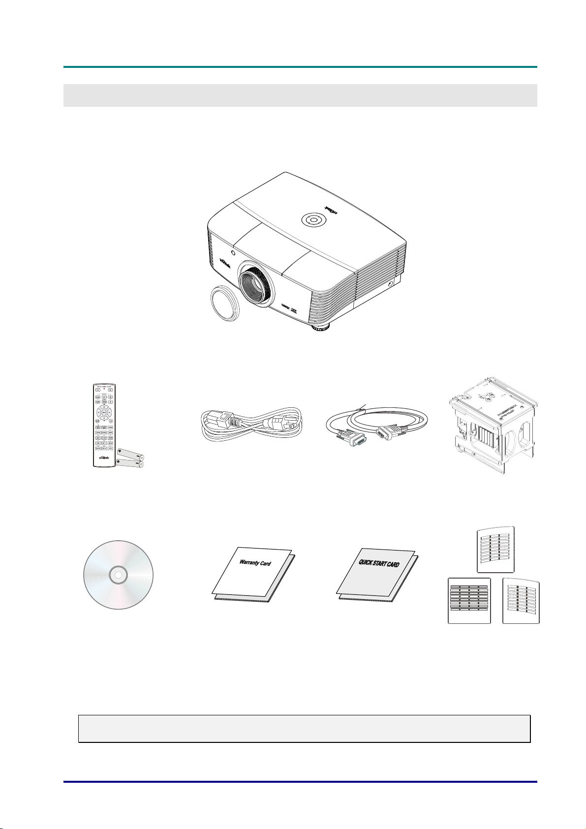
Packing Checklist
Carefully unpack the projector and check that the following items are included:
PROJECTOR WITH LENS CAP
EMOTE CONTROL
R
ITH TWO AA BATTERIES)
(W
CD-ROM
HIS USER’S MANUAL)
(T
P
OWER CORD VGA CABLE (1.8M)
W
ARRANTY CARD QUICK START CARD DUST FILTER
T
ILT LAMP MODULE
(O
(O
Contact your dealer immediately if any items are missing, appear damaged, or if the unit does not
work. It is recommend that you keep the original packing material should you ever need to return
the equipment for warranty service.
Caution:
Avoid using the projector in dusty environments.
PTIONAL)
PTIONAL)
— 1 —
DLP Projector—User’s Manual
3
67810
9
Views of Projector Parts
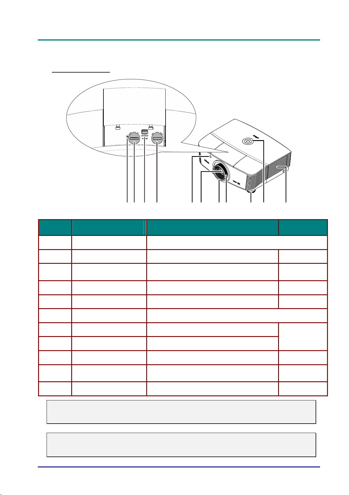
Front-right View
2
4
5
111
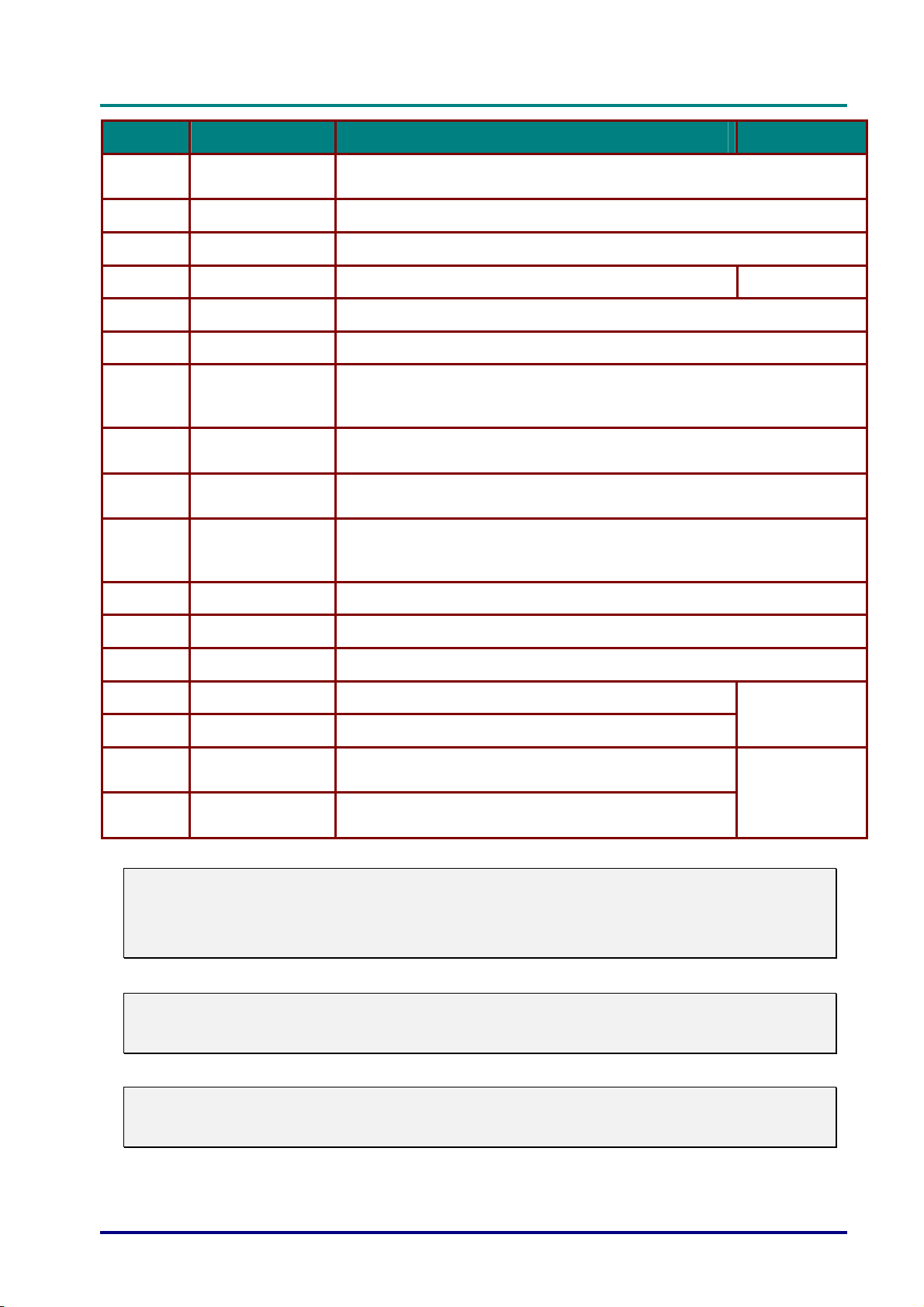
ITEM LABEL DESCRIPTION SEE PAGE:
1.
2.
3.
4.
5.
6.
7.
Screw For ensure the lens position
Vertical lens shift Adjusts the image position vertically
Lens release button
Horizontal lens shift Adjusts the image position horizontally
IR receiver Receives IR signal from remote control
Lens Projection Lens
Focus ring Focuses the projected image
Press the release button before removing the
lens
18
11
20
7
22
8.
9.
10.
Zoom ring Enlarges the projected image
Height adjuster Adjusts level of projector
Function keys
See Top view—On-screen Display (OSD)
buttons and LEDs.
17
3
11.
Important:
Ventilation openings on the projector allow for good air circulation, which keeps the projector
lamp cool. Do not obstruct any of the ventilation openings.
Note:
Suggest to loosen the screw before lens shift adjustment and tighten up after finished
adjustment.
Lamp cover Removes cover to replace lamp module
— 2 —
52
D
L
P
P
r
o
D
L
D
L
j
P
P
r
o
j
P
P
r
o
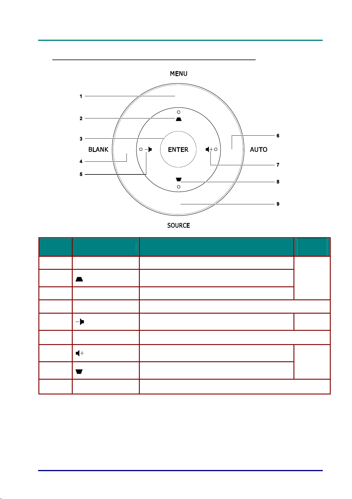
Top view—On-screen Display (OSD) buttons and LEDs
e
c
t
o
r
—
U
s
e
r
’
s
M
a
n
u
a
l
e
c
t
o
r
—
U
s
e
r
’
s
j
e
c
t
o
r
—
U
M
s
e
r
’
s
M
a
n
u
a
l
a
n
u
a
l
ITEM LABEL DESCRIPTION
1.
2.
3.
4.
5.
6.
7.
8.
9.
MENU Opens and exits OSD menus
ENTER Enter or confirm highlighted OSD menu item
BLANK Displays a blank screen and mutes audio
AUTO Optimizes image size, position, and resolution
SOURCE Enter the Source menu
Navigates and changes settings in the OSD
Quick Menu – For Keystone
Navigates and changes settings in the OSD
Quick Menu – For Volume -
Navigates and changes settings in the OSD
Quick Menu – For Volume +
Navigates and changes settings in the OSD
Quick Menu – For Keystone
SEE
PAGE:
24
24
24
– 3 –
DLP Projector—User’s Manual
1617
3
5
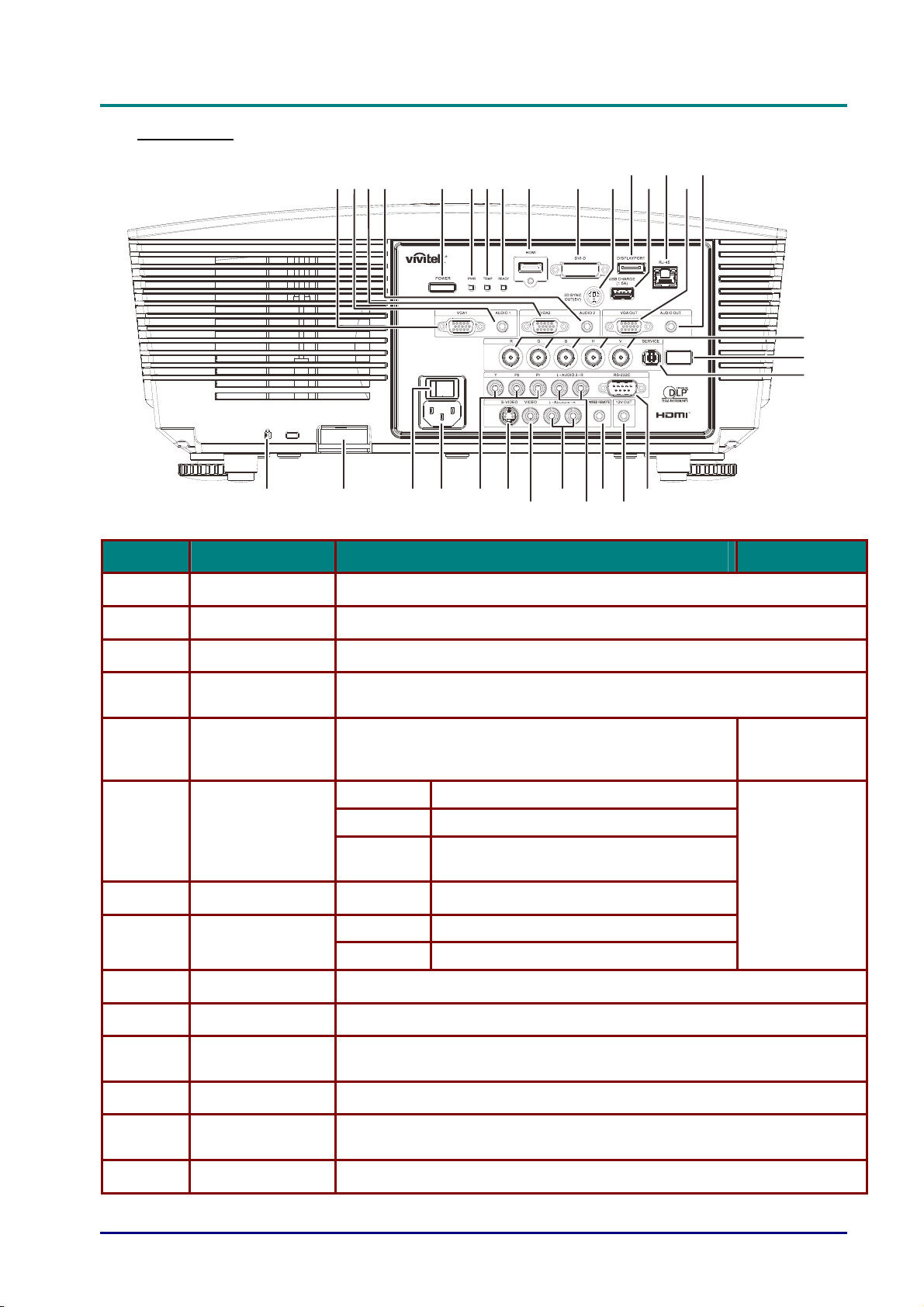
Rear view
12
4
3
56789
262728293031
2
10 1112131415
24
2
22
20
21
18
19
ITEM LABEL DESCRIPTION SEE PAGE:
1.
2.
VGA1 Connect a RGB cable from a computer or a video enabled device.
AUDIO IN 1 Connect the AUDIO cable from an input device.
3.
4.
5.
6.
7.
8.
9.
10.
11.
12.
VGA2 Connect a RGB cable from a computer or a video enabled device.
AUDIO IN 2
POWER
PWR LED
TEMP LED Red Over temperature
READY LED
HDMI Connect the HDMI cable from a HDMI device.
DVI-D Connect the DVI cable from a computer.
3D SYNC OUT
(5V)
DISPLAYPORT Connect a DISPLAYPORT cable to a DISPLAYPORT source.
Connect the AUDIO cable from an input device.
Note: Share with DVI & BNC audio input.
Turns the projector on or off (main power switch must
be turned on first). Press to place the projector in
standby mode.
Red Standby, Over Temperature
Blue Lamp Lit , System stable
Flashing
Red Lamp Lit , System stable, Lamp Fail
Flashing Error code (See as LED indicator table)
Connect 3D IR glasses receiver unit.
Power on, Cooling, Error code (See as
LED indicator table)
13
63
13.
14.
USB CHARGE
(1.5A)
RJ-45 Connect a LAN cable from Ethernet.
For USB charge.
— 4 —
D
L
P
P
r
o
j
e
c
t
o
r
—
U
s
e
r
’
s
M
a
n
u
D
D
L
P
P
r
o
j
e
c
t
o
r
—
U
s
e
r
’
s
L
P
P
r
o
j
e
c
t
o
r
—
U
s
e
r
’
s
M
M
a
a
n
u
a
a
n
u
a
ITEM LABEL DESCRIPTION SEE PAGE:
l
l
l
15.
16.
17.
18.
19.
20.
21.
22.
23.
24.
25.
VGA OUT
AUDIO OUT Connect an AUDIO cable for audio loop through.
BNC Connect a BNC cable from a computer.
IR receiver Receive IR signal from remote control.
SERVICE For service use.
RS-232 Connects RS-232 serial port cable for remote control.
12V
WIRED REMOTE
AUDIO IN 3 L/R
RCA (YPbPr)
AUDIO IN 4 L/R
RCA (Video/ SVideo)
VIDEO Connect the composite cable from a video device.
Connect the RGB cable to a display.
(Pass through by VGA1 only)
When connected to the screen through a commercially available cable,
the screen deploys automatically on start up of the projector. The screen
retracts when the projector is powered off (see notes below).
Wire remote control connector (connect with wire remote connector of the
Remote Control set).
Connect the audio cables from a audio device.
Connect the audio cables from a audio device.
7
26.
27.
28.
29.
30.
31.
Note:
y
To use this feature, you must plug in the connector before turn on/off the projector.
y
Screen controllers are supplied and supported by screen manufacturers.
y
Do not use this jack for anything other than intended use.
Note:
If your video equipment has both S-VIDEO and RCA jacks (composite video) connect to the
S-VIDEO connector. S-VIDEO provides a better quality signal.
S-VIDEO Connect the S-video cable from a video device.
YPbPr Connect a component video enabled device.
AC IN Connects the power cable.
Power switch Turns on/off the projector.
Security chain
lock
Kensington Lock
Helps protect the projector from unauthorized use.
Secures to permanent object with a Kensington® Lock
system.
13
61
Warning:
As a safety precaution, disconnect all power to the projector and connecting devices before
making connections.
– 5 –
DLP Projector—User’s Manual
Bottom view
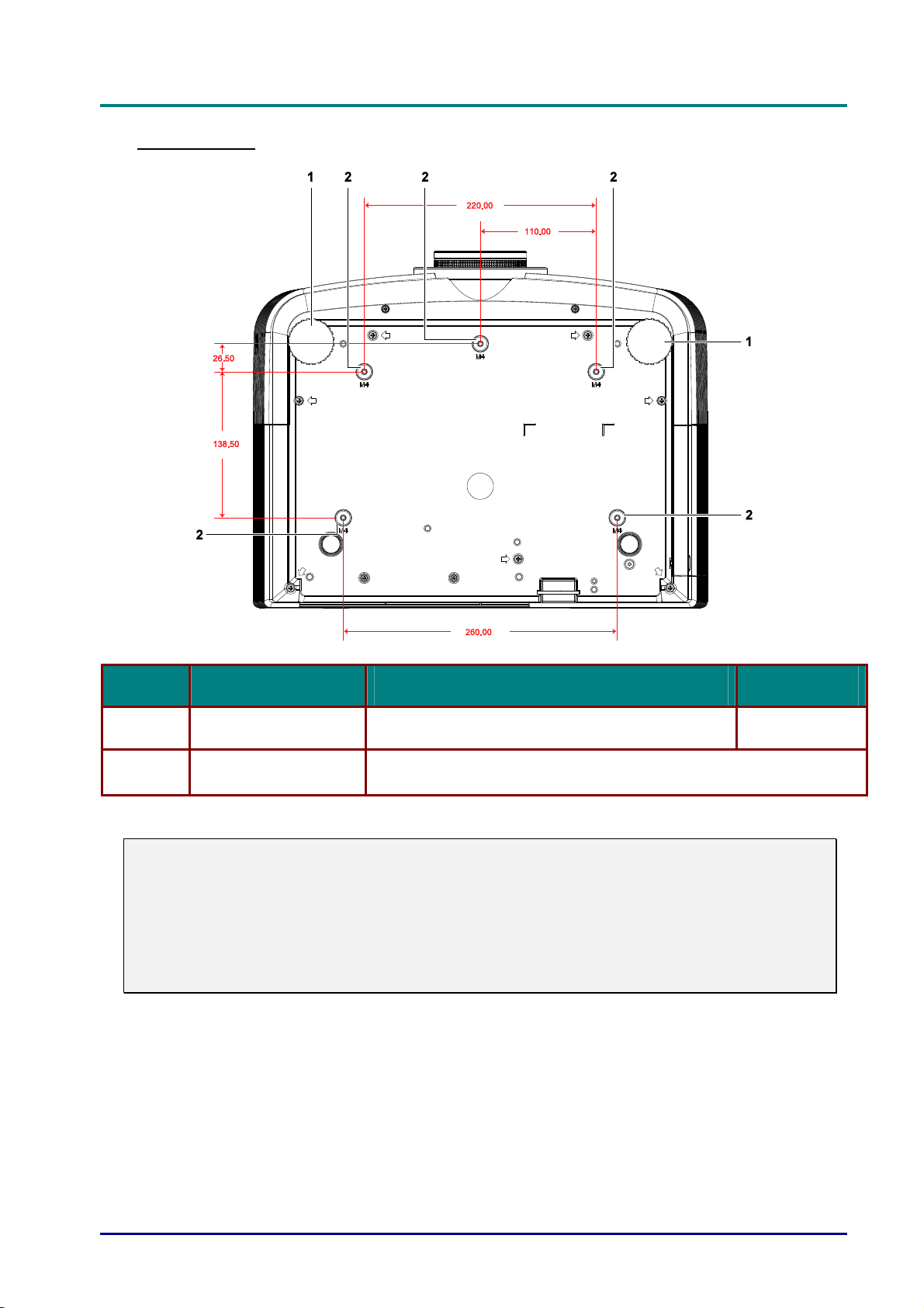
ITEM LABEL DESCRIPTION SEE PAGE:
1.
2.
Note:
When installing, ensure that you use only UL Listed ceiling mounts.
For ceiling installations, use approved mounting hardware and M4 screws with a maximum
screw depth of 6 mm (0.23 inch).
The construction of the ceiling mount must be of a suitable shape and strength. The ceiling
mount load capacity must exceed the weight of the installed equipment, and as an additional
precaution be capable of withstanding three times the weight of the equipment (not less than
5.15 kg) over a period of 60 seconds.
Tilt adjustor Rotate adjuster lever to adjust angle position.
Ceiling support holes
Contact your dealer for information on mounting the projector on a
ceiling
17
— 6 —
Remote Control Parts
D
D
D
L
P
P
r
o
j
e
c
t
o
r
—
U
s
e
r
’
s
M
a
n
u
a
l
L
P
P
r
o
j
e
c
t
o
r
—
U
s
e
r
’
s
L
P
P
r
o
j
e
c
t
o
r
—
U
M
s
e
r
’
s
M
a
n
u
a
l
a
n
u
a
l
Important:
1. Avoid using the projector with bright fluorescent lighting turned on. Certain high-frequency
fluorescent lights can disrupt remote control operation.
2. Be sure nothing obstructs the path between the remote control and the projector. If the path
between the remote control and the projector is obstructed, you can bounce the signal off
certain reflective surfaces such as projector screens.
3. The buttons and keys on the projector have the same functions as the corresponding buttons
on the remote control. This user’s manual describes the functions based on the remote control.
– 7 –

DLP Projector—User’s Manual
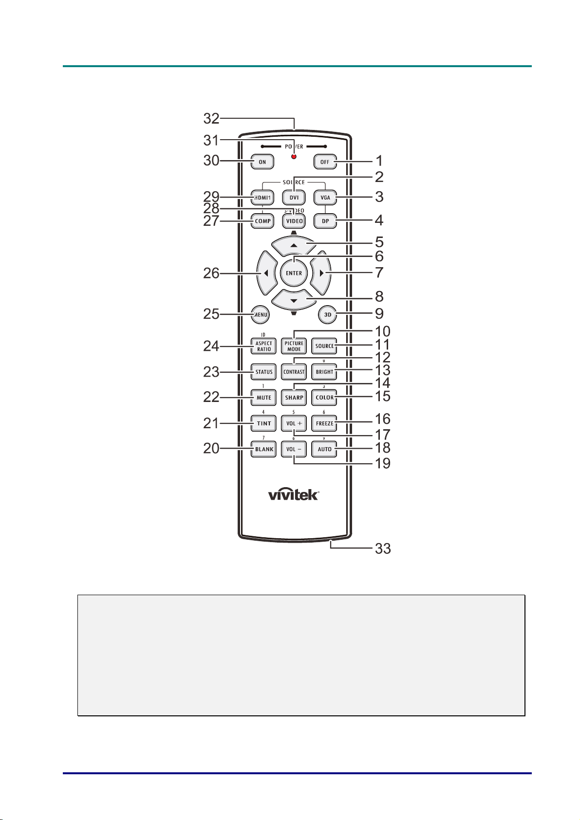
ITEM LABEL DESCRIPTION SEE PAGE:
1.
2.
Power OFF Turns the projector off
DVI Displays the DVI source selection
13
3.
4.
5.
6.
7.
8.
9.
10.
11.
12.
13.
14.
15.
16.
17.
VGA Displays the VGA source selection
DP Displays the DisplayPort source selection
Up cursor /
Keystone+
ENTER Enters and confirms settings in the OSD
Right cursor Navigates and changes settings in the OSD
Down cursor /
Keystone-
3D Activate 3D video (not available in D5180HD series)
PICTURE MODE Changes the Display Mode setting
SOURCE Alternate input source
CONTRAST Displays the contrast settings bar
BRIGHT Displays the brightness setting bar
SHARP Displays the sharpness setting bar
COLOR Displays the color setting bar
FREEZE Freezes/unfreezes the on-screen picture
VOL + Adjusts volume
Navigates and changes settings in the OSD
Quick Menu – For Keystone
Navigates and changes settings in the OSD
Quick Menu – For Keystone
24
24
18.
19.
20.
21.
22.
23.
24.
25.
26.
27.
28.
29.
30.
31.
32.
33.
AUTO Auto adjustment for frequency, phase, and position
VOL - Adjusts volume
BLANK Makes the screen blank
TINT Displays the tint setting bar
MUTE Mutes the built-in speaker
STATUS
ASPECT RATIO Displays the ASPECT RATIO selections
MENU
Left cursor Navigates and changes settings in the OSD
COMP Displays the Component source selection
VIDEO Displays the VIDEO source selection
HDMI 1 Displays the HDMI 1 source selection
Power ON Turns the projector on
Status LED Lights when the remote control is used
IR transmitter Transmits signals to projector
Wired remote
connector
Opens the OSD Status menu (the menu only opens when an input
device is detected)
Opens
Wired remote function
or closed the OSD
used
24
24
24
13
— 8 —

D
L
P
P
r
o
j
e
c
t
o
r
—
U
s
e
r
’
D
D
L
P
P
r
o
j
e
c
t
o
r
L
P
P
r
o
—
j
e
c
t
o
r
—
U
U
s
s
e
r
’
s
e
r
’
Remote Control Operating Range
The remote control uses infrared transmission to control the projector. It is not necessary to point
the remote directly at the projector. Provided you are not holding the remote perpendicular to the
sides or the rear of the projector, the remote will function well within a radius of about 7 meters (23
feet) and 15 degrees above or below the projector level. If the projector does not respond to the
remote control, move a little closer.
Projector and Remote Control Buttons
The projector can be operated using the remote control or the buttons on the top of the projector.
All operations can be carried out with the remote control; however, the buttons on the projector
are limited in use.
M
a
n
u
a
l
s
M
s
M
a
n
u
a
l
a
n
u
a
l
– 9 –
DLP Projector—User’s Manual
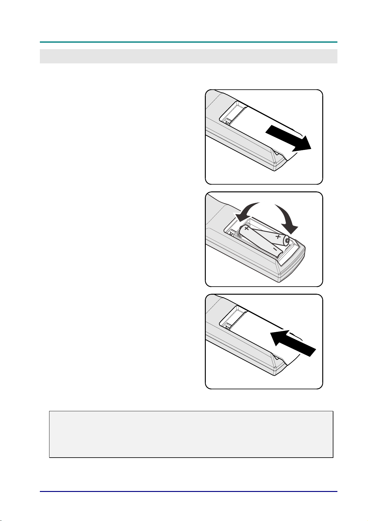
Inserting the Remote Control Batteries
Remove the battery compartment
1.
cover by sliding the cover in the
direction of the arrow.
Insert the battery with the positive
2.
side facing up.
SETUP AND OPERATION
Replace the cover.
3.
Caution:
1. Only use AA batteries (Alkaline batteries are recommended).
2. Dispose of used batteries according to local ordinance regulations.
3. Remove the batteries when not using the projector for prolonged periods.
— 10 —
D
L
P
P
r
o
j
e
c
t
o
r
—
D
D
L
P
P
r
o
j
e
L
P
c
P
r
o
j
e
c
U
t
o
r
—
U
t
o
r
—
U
Installing or Removing the Optional Lens
Caution:
y
Do not shake or place excessive pressure on the projector or the lens components as the
projector and lens components contain precision parts.
y
Before removing or installing the lens, be sure to turn off the projector, wait until the cooling
fans stop, and turn off the main power switch.
y
Do not touch the lens surface when removing or installing the lens.
y
Keep fingerprints, dust or oil off the lens surface.
y
Do not scratch the lens surface.
y
Work on a level surface with a soft cloth under it to avoid scratching.
y
If you remove and store the lens, attach the lens cap to the projector to keep off dust and dirt.
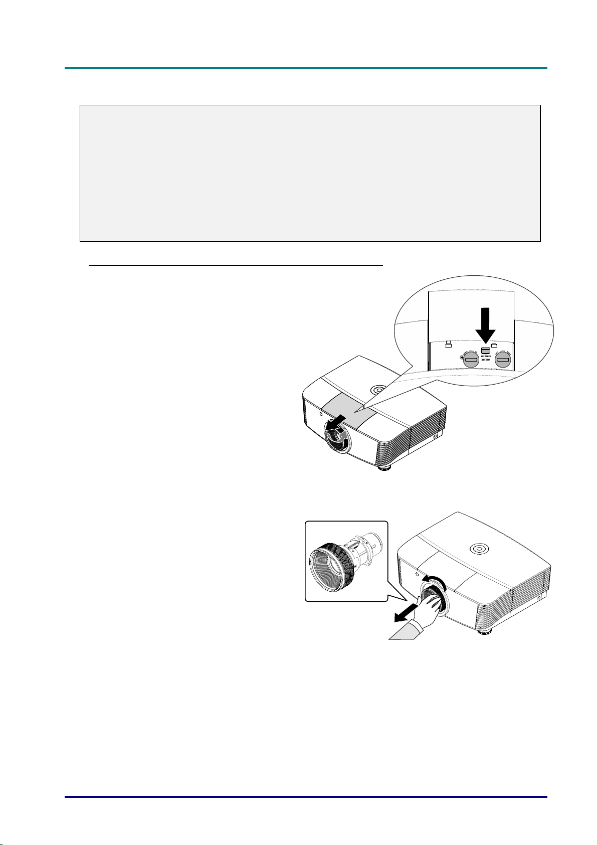
Removing the Existing Lens From the Projector
Pull and release the top cover to
1.
open as shown.
s
e
r
’
s
M
a
n
u
a
l
s
e
r
’
s
M
s
e
r
’
s
M
a
n
u
a
l
a
n
u
a
l
Push the LENSE RELEASE button
2.
to the unlock position.
Grasp the lens.
3.
Rotate the lens counterclockwise.
4.
The existing lens will be
disengaged.
Pull out the existing lens slowly.
5.
– 11 –
DLP Projector—User’s Manual
El
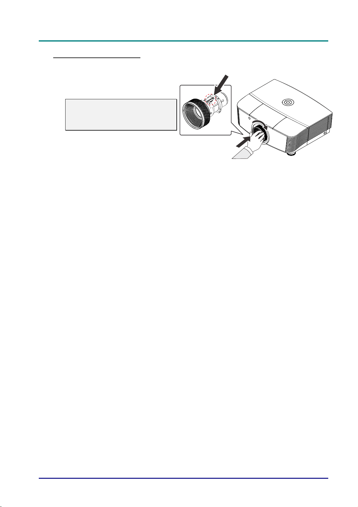
Installing the New Lens
Align the notches and correctly
1.
position the electrical contact pad as
shown in the picture.
Note:
Pin of Electrical contact pins should
be in the direction as shown in the
picture.
Rotate the lens clockwise until you
2.
feel it click into place.
ectrical contact pins
— 12 —
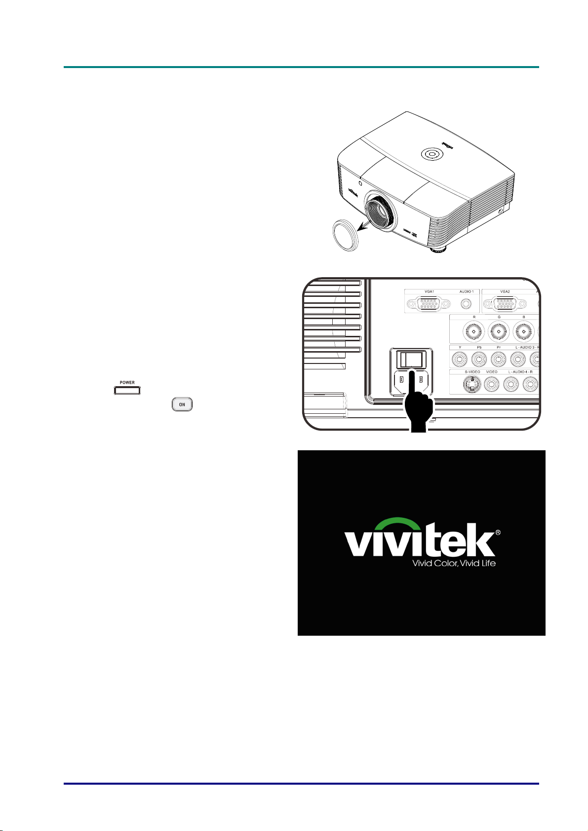
Starting and Shutting down the Projector
Remove the lens cap.
1.
Securely connect the power cord
2.
and signal cable. When connected,
the power led will turn red.
D
D
D
L
P
P
r
o
j
e
c
t
o
r
—
U
s
e
r
’
s
M
a
n
u
a
l
L
P
P
r
o
j
e
c
t
o
r
—
U
s
e
r
’
s
L
P
P
r
o
j
e
c
t
o
r
—
U
M
s
e
r
’
s
M
a
n
u
a
l
a
n
u
a
l
Turn on the lamp by pressing
3.
“
projector or “
control.
The PWR LED will now flash red.
The startup screen will display in
approximately 30 seconds. The first
time you use the projector, you can
select your preferred language from
quick menu after the startup screen
display.
” button on the rear of the
” on the remote
– 13 –
DLP Projector—User’s Manual
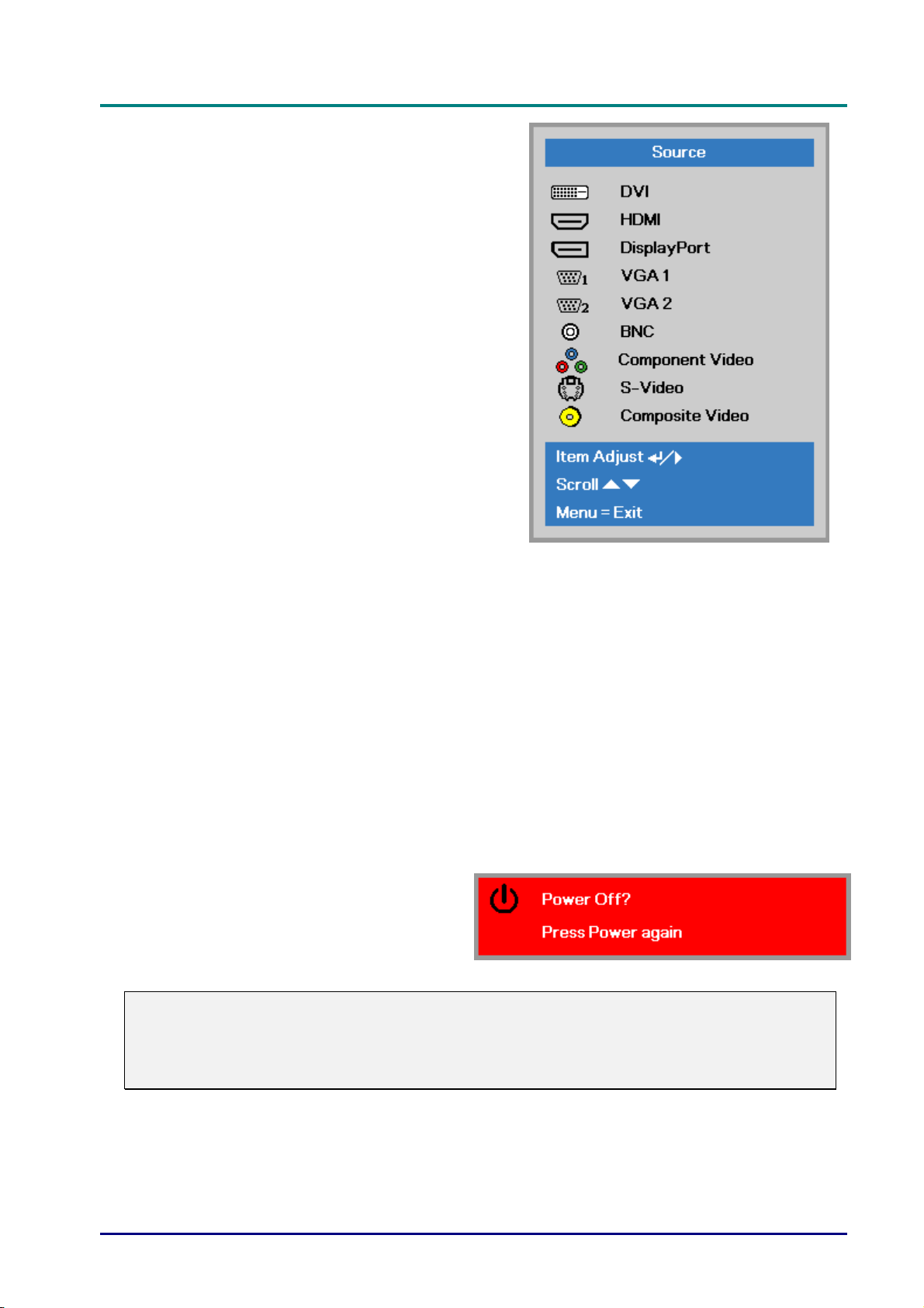
If more than one input device is
4.
connected, press the SOURCE
button and use ▲▼ to scroll among
devices.
• DVI: Digital Visual Interface
• HDMI: High-Definition Multimedia Interface
• DisplayPort: Digital display interface
• VGA 1 / 2: Analog RGB 1 / 2
• BNC: Analog RGB (BNC connector)
•
Component Video: DVD input YCbCr / YPbPr , or
• S-Video: Super video (Y/C separated)
• Composite Video: Traditional composite video
When the “Power Off? /Press
5.
Power again” message appears,
press the POWER button. The
projector turns off.
Caution:
1. Be sure to remove the lens cap before starting projector.
compatible
HDTV input YPbPr
2. Do not unplug the power cord until the READY LED stops flashing–indicating the projector
has cooled down.
— 14 —
D
L
P
P
r
o
j
e
c
t
o
r
—
U
s
D
D
L
P
P
r
o
j
e
c
t
o
L
P
P
r
o
r
j
e
c
t
o
r
—
—
U
U
e
s
s
Setting an Access Password (Security Lock)
You can use the four (arrow) buttons to set a password and prevent unauthorized use of the
projector. When enabled, the password must be entered after you power on the projector. (See
Navigating the OSD on page 24 and Setting the OSD Language on page 25 for help on using
OSD menus.)
Important:
Keep the password in a safe place. Without the password, you will not be able to use the
projector. If you lose the password, contact your reseller for information on clearing the
password.
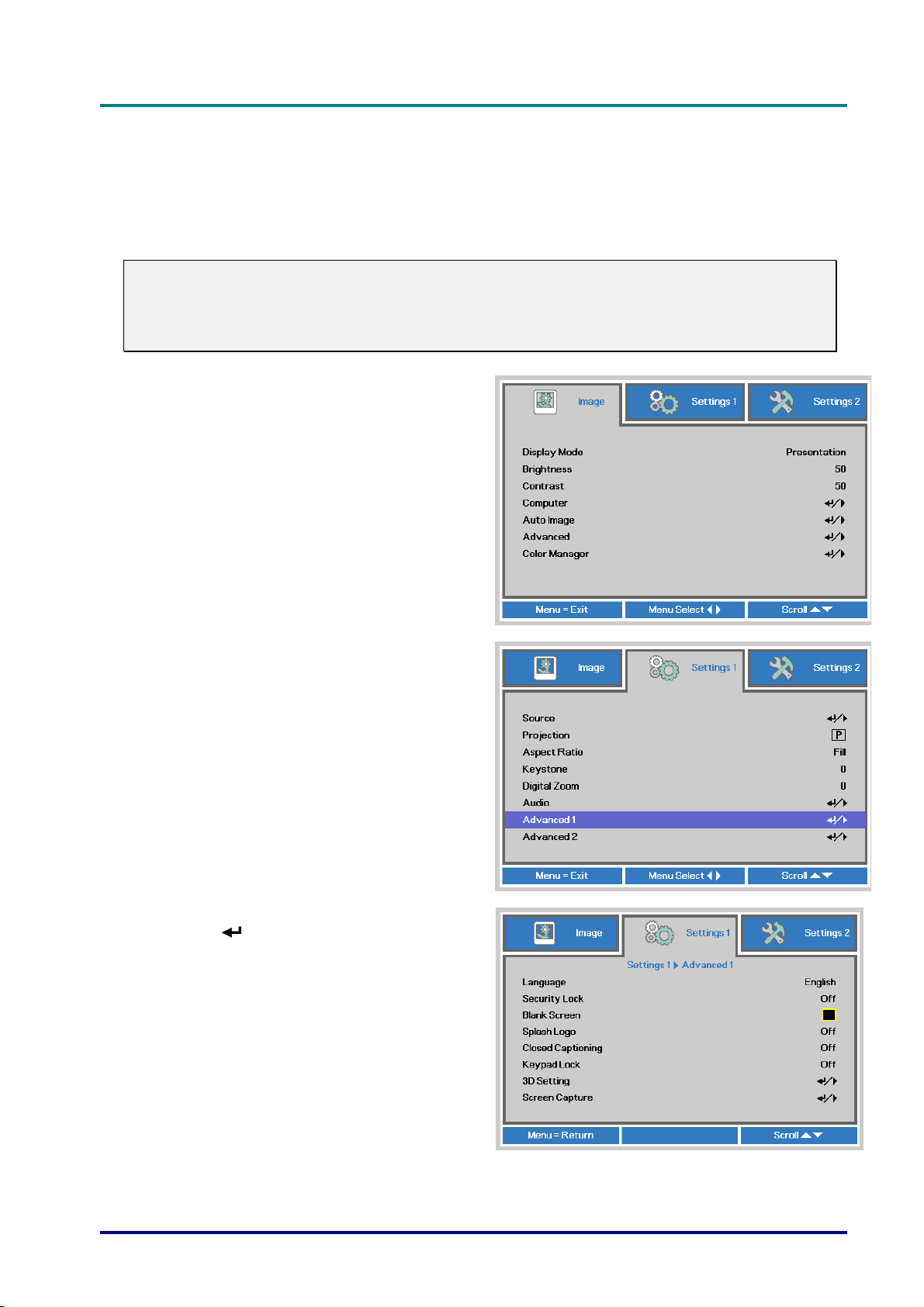
Press the MENU button to open the
1.
OSD menu.
r
’
s
M
a
n
u
a
l
e
r
’
s
M
e
r
’
s
M
a
n
u
a
l
a
n
u
a
l
Press the cursor ◄► button to move to
2.
the Settings 1 menu, press the cursor
▲▼ button to select Advanced 1.
Press (Enter) / ► to enter the
3.
Advanced 1 sub menu. Press the
cursor ▲▼ button to select Security
Lock.
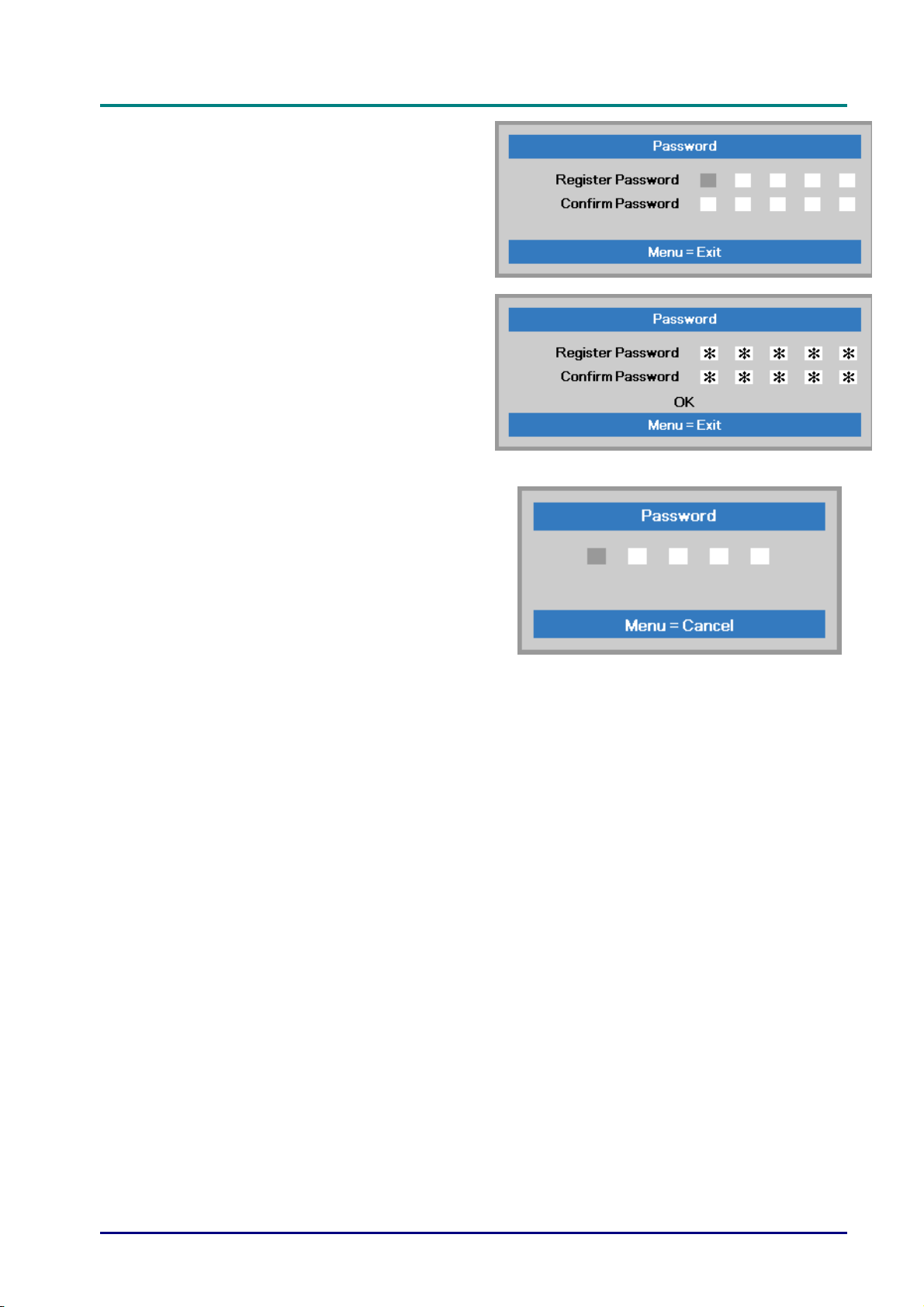
Press the cursor ◄► button to enter
4.
and enable or disable security lock
function.
A password dialog box automatically
appears.
– 15 –
DLP Projector—User’s Manual
You can use the cursor buttons
5.
▲▼◄►
either on keypad or IR remote control
for password entry. You can use any
combination including the same arrow
five times, but not less than five.
Press the cursor buttons in any order to
set the password. Push the MENU
button to exit the dialog box.
The password confirm menu appears
6.
when user presses the power-on key in
case the Security Lock is enabled.
Enter the password in the order you set
it at step 5. In case you forget the
password, please contact the service
center.
The service center will validate the
owner and help reset the password.
— 16 —
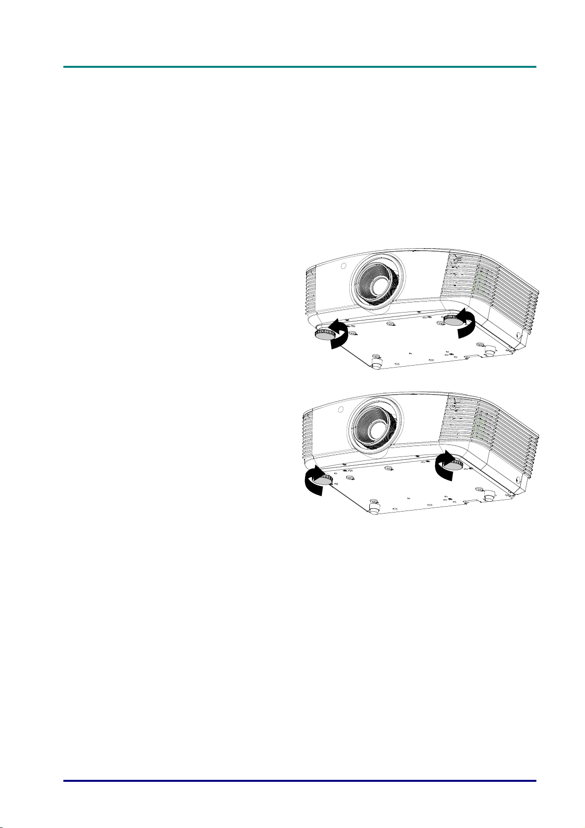
Adjusting the Projector Level
Take note of the following when setting up the projector:
• The projector table or stand should be level and sturdy.
• Position the projector so that it is perpendicular to the screen.
• Remove the Back Foot Holder on the rear adjuster foot before adjusting the projection
angle.
• Ensure the cables are in a safe location. You could trip over them.
To raise the level of the projector,
1.
twist the adjusters counter
clockwise.
D
L
P
P
r
o
j
e
c
t
o
r
—
U
s
e
r
’
s
M
a
n
u
a
l
D
L
P
P
r
o
j
e
c
t
o
r
—
U
s
e
r
’
s
D
L
P
P
r
o
j
e
c
t
o
r
—
U
M
s
e
r
’
s
M
a
n
u
a
l
a
n
u
a
l
To lower the level of the projector,
2.
lift the projector and twist the
adjusters clockwise.
– 17 –
DLP Projector—User’s Manual
S
UXGA /
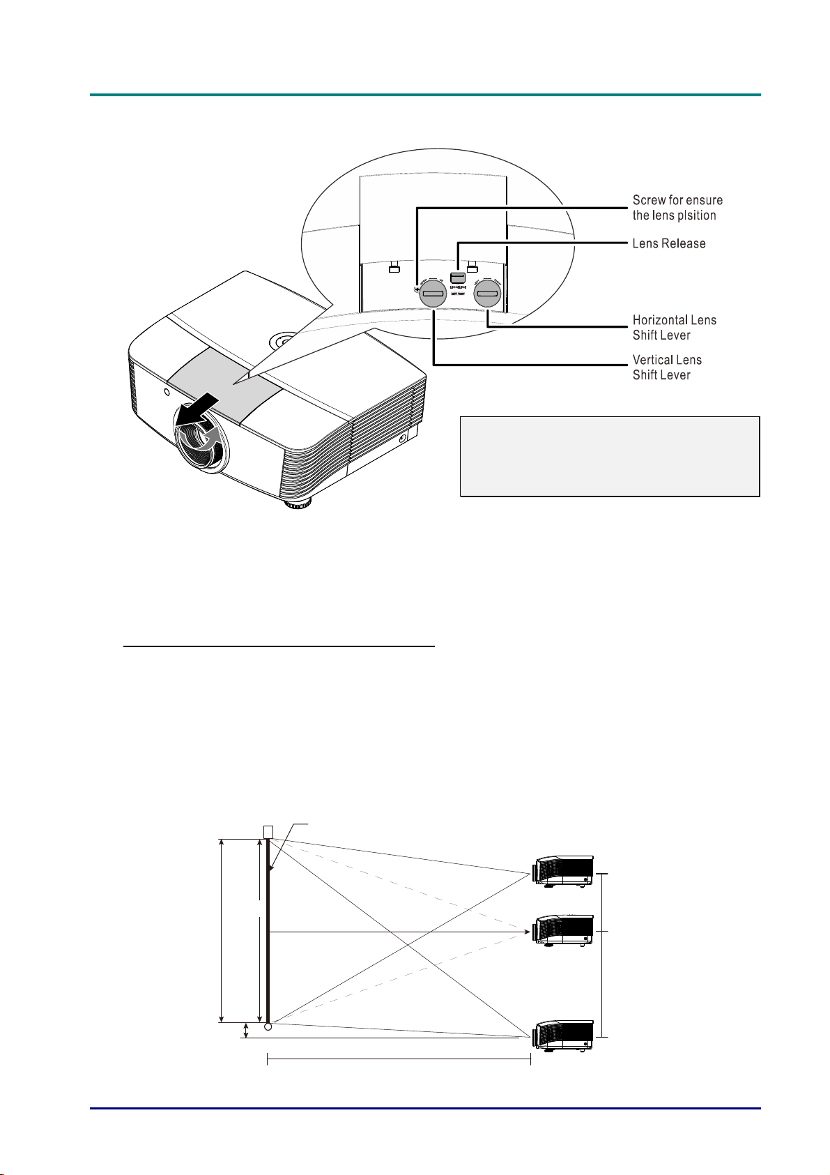
Adjusting Projected Image Position Using Shift
Note:
Suggest to loosen the screw before lens
shift adjustment and tighten up after
finished adjustment.
The Shift feature provides a lens shift function that can be used to adjust the position of the
projected image either horizontally or vertically within the range detailed below.
Shift is a unique system that provides lens shift while maintaining a much higher ANSI contrast
ratio than traditional lens shift systems.
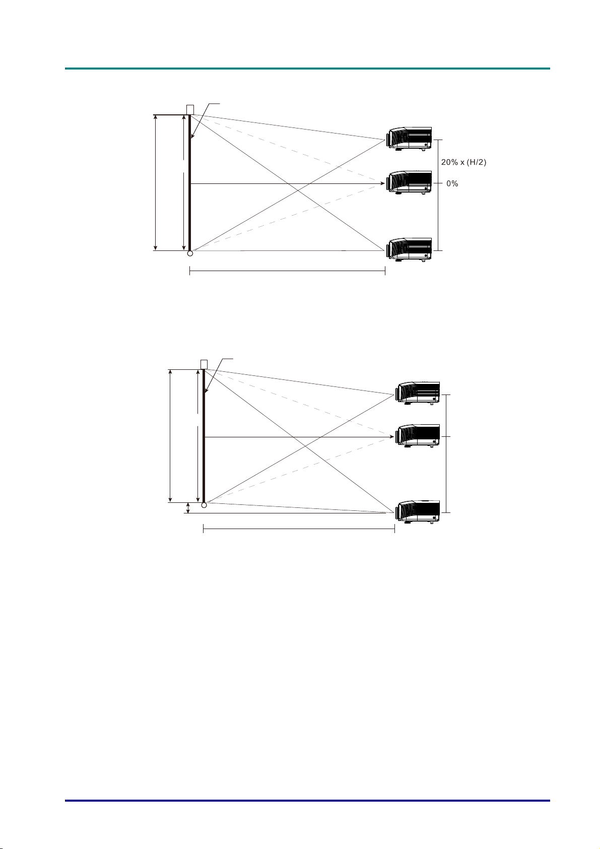
Adjusting the vertical image position
The vertical image height can be adjusted between 110% and -30% ( WUXGA, WXGA), 100%
and -20% (XGA), 120% and -40% ( 1080P) of offset position. Note that the maximum vertical
image height adjustment can be limited by the horizontal image position. For example it is not
possible to achieve the maximum vertical image position height detailed above if the horizontal
image position is at maximum. Please consult the Shift Range diagram below for further
clarification.
WUXGA and WXGA
creen
-30%
100%
(H)
30% x (H/2)
0%
Screen Height
(H/2) x 10%
W
Distance
(L)
WXGA
— 18 —
110% x (H/2)
+110%
XGA
H
GA
)
S
080
)
1080P
D
L
P
P
r
o
j
e
c
t
o
r
—
U
s
e
r
’
s
M
a
n
u
a
l
D
L
P
P
r
o
j
e
c
t
o
r
—
U
s
e
r
’
s
D
L
P
P
r
o
j
e
c
t
o
r
—
U
Screen
-20%
100%
eight
(H)
Screen
100% x (H/2
+100%
Distance
(L)
X
M
s
e
r
’
s
M
a
n
u
a
l
a
n
u
a
l
Screen Height
(H/2) x 20%
100%
(H)
creen
Distance
(L)
P
1
-40%
40% x (H/2)
0%
120% x (H/2
+120%
– 19 –
DLP Projector—User’s Manual
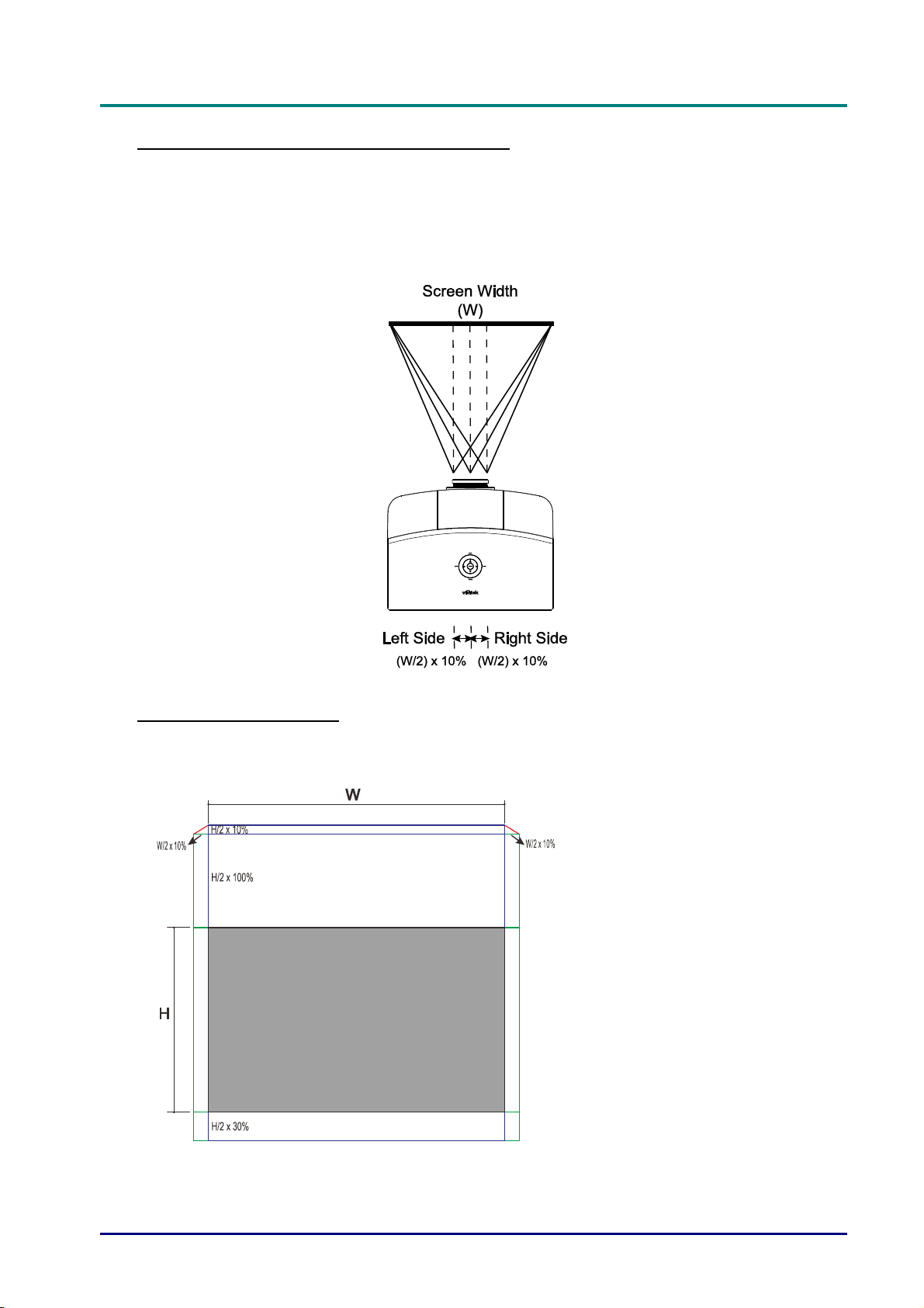
Adjusting the horizontal image position
With the lens in the center position the horizontal image position can be adjusted to the left or right
by up to a maximum of 10% of the half image width. Note that the maximum horizontal image
height adjustment can be limited by the vertical image position. For example it is not possible to
achieve the maximum horizontal image position if the vertical image position is at maximum.
Please consult the Shift Range diagram below for further clarification.
Shift Range Diagram
WUXGA and WXGA
The max H up shift = H/2 x 110%
The max H down shift = H/2 x 30%
The max W shift = W/2 x 10%
When max W shift is W/2 x 10%
max H shift = H/2 x 100%
When max H shift is H/2 x 110%
max W shift = H x 0%
— 20 —
 Loading...