

Page 1

Copyright
This publication, including all photographs, illustrations and software, is protected under international copyright laws, with all rights reserved. Neither this manual, nor any of the material contained herein, may be
reproduced without written consent of the author.
© Copyright February, 2006
Disclaimer
The information in this document is subject to change without notice. The manufacturer makes no representations or warranties with respect to the contents hereof and specifically disclaims
any implied warranties of merchantability or fitness for any particular purpose. The manufacturer
reserves the right to revise this publication and to make changes from time to time in the content hereof
without obligation of the manufacturer to notify any person of such revision or changes.
Trademark Recognition
Kensington is a U.S. registered trademark of ACCO Brand Corporation with issued registrations and pending applications in other countries throughout the world.
All other product names used in this manual are the properties of their respective owners and
are ac- knowledged.
Page 2

Page 3

P
P
e
eff
f
e
e
Important Safety Information
Congratulations on purchasing the DLP projector!
Important:
It is
strongly recommended
safety
Keep this
Symbols Used
Warning symbols are used on the unit and in this manual to alert you of hazardous situations.
The following styles are used in this manual to alert you to important information.
that
you read
and usage instructions will ensure
manual
for future reference.
this section
that
carefully before using
you enjoy many years
of safe
the projector.
use
of the projector.
These
Note:
Provides additional
Important:
Provides additional
Caution:
Alerts
Warning:
Alerts
sonal injury.
Throughout this manual, component parts and items in the OSD menus are denoted in bold font as in this
example:
“Push the Menu button on the remote control to open the Main menu.”
you
to situations that
you
to situations that
informat
ion on
the topic at
information that
may damage
may damage
should
not be
the unit.
the unit,
hand.
overlooked.
create a hazardous environment, or cause per-
Remote Control
Some remote controls have a laser for pointing out items on a screen.
DANGER: Do not point the laser in the eyes. Doing so can damage the eyes permanently.
General Safety Information
¤
Do not open the unit case. Aside from the projection lamp, there are no user-serviceable parts in
the unit. For servicing, contact qualified service personnel.
¤
Follow all warnings and cautions in this manual and on the unit case.
¤
The projection lamp is extremely bright by design. To avoid damage to eyes, do not look into the
lens when the lamp is on.
¤
Do not place the unit on an unstable surface, cart, or stand.
¤
Avoid using the system near water, in direct sunlight, or near a heating device.
¤
Do not place heavy objects such as books or bags on the unit.
r
a
c
r
a
c
P
e
r
e
a
c
– 1 –
Page 4

D
L
LPP
P PP
P
j
jee
e
t
t
U
U
e
e
’
’
D
D
o
r
o
r
o
L
r
—
r
c
o
c
t
j
c
s
r
U
s
s
r
s
’
s
e
r
s
—
r
o
—
r
o
M
M
M
a
u
n
a
l
a
u
n
a
l
a
u
n
a
l
Power Safety
¤
Only use the supplied power cord.
¤
Do not place anything on the power cord. Place the power cord where it will not be in the way of
¤
Remove the batteries from the remote control when storing or not in use for a prolonged period.
Replacing the Lamp
foot traffic.
Replacing the lamp can be hazardous if done incorrectly. Refer to “Replacing the Projection
Lamp” on page 38 for clear and safe instructions for this procedure. Before replacing the lamp:
¤
Spent Lamp Management
Cleaning the Projector
Regulatory Warnings
Unplug the power cord.
¤
Allow the lamp to cool for about one hour.
¤
This product contains a metal halide lamp, which contains mercury. Dispose of it as required by lo-
cal ordinances and regulations.
¤
The USA restricts or prohibits the disposal of some or all mercury containing lamps in the municipal
waste stream. Please visit www.lamprecycle.org for more information on specific state disposal requirements and recycling facilities.
¤
The following states have laws that deal with information that wholesalers must provide to contrac-
tors for lamp disposal.
Connecticut
Maine
Minnesota
Rhode Island
¤
For users in Connecticut, please call our toll free number1-888-657-5267 to place an order for the
delivery of a kit for returning a used lamp. The kit includes a box for the lamp, tape, and a return
shipping label. To return a lamp:
1. Place the lamp in the box, complete the enclosed form, and seal the box with the provided tape.
2. Affix the return shipping label to the box and call 1.800.463.3339 FedEx Ground Service
for box pickup.
¤
Unplug the power cord before cleaning. Refer to “Cleaning the Projector” on page 41.
¤
Allow the lamp to cool for about one hour.
Before installing and using the projector, read the regulatory notices in the “Regulatory Compliance” section on page 55.
Page 5

P
P
e
eff
f
e
e
—1—
Main Features
•
Lightweight unit, easy to pack away and transport
Compatible with all major video standards including NTSC, PAL, and SECAM
•
A
high brightness rating allows for presentations in daylight or in lit rooms
•
•
Supports resolutions up to UXGA at 16.7 million colors to deliver crisp, clear images
•
Flexible setup allows for front, rear, and ceiling projections
•
Line-of-vision projections remain square, with advanced keystone correction for angled
projections
•
Input source automatically detected
About
this
manual
This manual is intended for end users and describes how to install and operate the DLP projector. Wherever possible, relevant information—such as an illustration and its description—has been kept
on one page. This printer-friendly format is both for your convenience and to help save paper, thereby
protecting the environment. It is suggested that you only print sections that are relevant to your needs.
r
a
c
r
a
c
P
e
r
e
a
c
Page 6

L
LPP
P PP
P
j
jee
e
t
t
U
U
e
e
’
’
D
D
D
o
r
o
r
o
L
r
—
r
c
o
c
t
j
c
s
r
U
s
s
r
s
’
s
e
r
s
—
r
o
—
r
o
M
M
M
a
u
n
a
l
a
u
n
a
l
a
u
n
a
l
TU
GETTING STARTED
TU
P
ACKING CHECKLIST
TU
V
IEWS OF PROJECTOR PARTS
TU
Front-right View
TU
Top View—On-screen Display (OSD) Buttons and LEDs
TU
Side View Connectors
TU
Projector LED Descriptions
TU
Rear ViewUT........................................................................................................................................................................ 6
TU
Bottom ViewUT.................................................................................................................................................................... 7
TU
R
EMOTE CONTROL PARTS
TU
R
EMOTE
CONTROL
TU
P
ROJECTOR AND REMOTE CONTROL BUTTONS
TU
SETUP AND OPERATIONUT............................................................................................................................................... 11
TU
I
NSERTING THE REMOTE CONTROL BATTERIES
TU
C
ONNECTING
TU
S
TARTING AND SHUTTING DOWN THE PROJECTOR
TU
A
DJUSTING THE PROJECTOR LEVEL
TU
A
DJUSTING THE
TU
A
DJUSTING THE VOLUME
TU
ON-SCREEN DISPLAY (OSD) MENU SETTINGSUT....................................................................................................... 19
TU
OSD M
TU
Navigating the OSD
TU
S
ETTING THE
TU
P
ICTURE MENU
TU
Picture Menu Functions Available for Connected Source
TU
A
DVANCE MENU
TU
Advance Menu Functions Available for Connected Source
TU
S
ETUP
TU
Setup Menu Functions Available for Connected SourceUT............................................................................................... 29
TU
A
UDIO MENU
TU
Audio Menu Functions Available for Connected Source
TU
W
INDOW MENU
TU
C
OLORMGR MENU
TU
S
ERVICE MENU
TU
N
ETWORK
TU
MAINTENANCE AND SECURITYUT................................................................................................................................. 38
TU
R
EPLACING THE PROJECTION LAMP
TU
Resetting the LampUT........................................................................................................................................................ 40
TU
C
LEANING THE PROJECTOR
TU
Cleaning the Lens
TU
Cleaning the Case
TU
U
SING THE KENSINGTON
TU
C
EILING INSTALLATION
TU
Securing the Mount to the Ceiling
TU
Using Support Cables
TU
TROUBLESHOOTING
TU
C
OMMON PROBLEMS AND SOLUTIONS
TU
T
IPS FOR
TU
LED E
TU
I
MAGE PROBLEMS
TU
L
AMP PROBLEMS
TU
R
EMOTE CONTROL PROBLEMS
TU
A
UDIO PROBLEMS
TU
H
AVING THE PROJECTOR SERVICED
INPUT
ENU CONTROLS
OSD L
UT
..................................................................................................................................................................... 27
MENU
UT
..................................................................................................................................................................... 31
MENU
TROUBLESHOOTING
RROR MESSAGES
UT
.......................................................................................................................................................... 1
UT
........................................................................................................................................................... 1
UT
............................................................................................................................................... 2
UT
............................................................................................................................................................. 2
UT
..................................................................................................................................................... 4
UT
........................................................................................................................................... 5
UT
................................................................................................................................................... 8
UT
OPERATING
UT
DEVICES
ZOOM
ANGUAGE
UT
.................................................................................................................................................................. 21
UT
............................................................................................................................................................... 24
UT
................................................................................................................................................................. 32
UT
............................................................................................................................................................ 34
UT
.................................................................................................................................................................. 35
UT
............................................................................................................................................................... 37
UT
......................................................................................................................................................... 41
UT
......................................................................................................................................................... 41
UT
.............................................................................................................................................................. 45
UT
............................................................................................................................................................... 46
UT
............................................................................................................................................................. 46
............................................................................................................................................ 12
, F
OCUS AND
UT
.................................................................................................................................................. 18
UT
..................................................................................................................................................... 19
UT
...................................................................................................................................................... 19
UT
.......................................................................................................................................... 20
UT
................................................................................................................................................ 41
® L
OCK
UT
..................................................................................................................................................... 42
UT
................................................................................................................................................... 43
UT
..................................................................................................................................................... 44
UT
............................................................................................................................................ 44
UT
.................................................................................................................................................... 45
UT
.......................................................................................................................................... 46
............................................................................................................................. 10
RANGE
UT
................................................................................................................................... 16
KEYSTONE
UT
................................................................................................................................... 38
UT
...................................................................................................................................... 42
UT
................................................................................................................................ 42
UT
............................................................................................................................... 44
UT
.................................................................................................................................. 47
Table of contents
UT
.............................................................................................. 3
UT
.................................................................................................................. 10
UT
................................................................................................................. 11
UT
............................................................................................................. 14
UT
................................................................................................................ 17
UT
............................................................................................ 23
UT
.......................................................................................... 25
UT
.............................................................................................. 31
Page 7

P
P
e
eff
f
e
e
—3—
r
a
r
P
r
e
TU
SPECIFICATIONSUT............................................................................................................................................................. 48
TU
S
PECIFICATIONS
TU
Input ConnectorsUT........................................................................................................................................................... 49
TU
Output Connectors
TU
Control ConnectorsUT....................................................................................................................................................... 49
TU
Optional LensUT................................................................................................................................................................ 49
TU
P
ROJECTION DISTANCE
TU
T
IMING MODE TABLE
TU
P
ROJECTOR DIMENSIONS
TU
REGULATORY COMPLIANCE
TU
FCC W
ARNING
TU
C
ANADA
TU
S
AFETY
CERTIFICATIONS
TU
EN 55022 W
UT
................................................................................................................................................................. 48
UT
........................................................................................................................................................ 49
V.S. P
ROJECTION SIZE
UT
........................................................................................................................................................ 51
UT
................................................................................................................................................... 54
UT
..................................................................................................................................... 55
UT
.................................................................................................................................................................. 55
UT
............................................................................................................................................................................ 55
UT
................................................................................................................................................... 55
ARNING
UT
......................................................................................................................................................... 55
(FOR
STANDARD LENS
)UT............................................................................. 50
c
a
c
e
a
c
Page 8
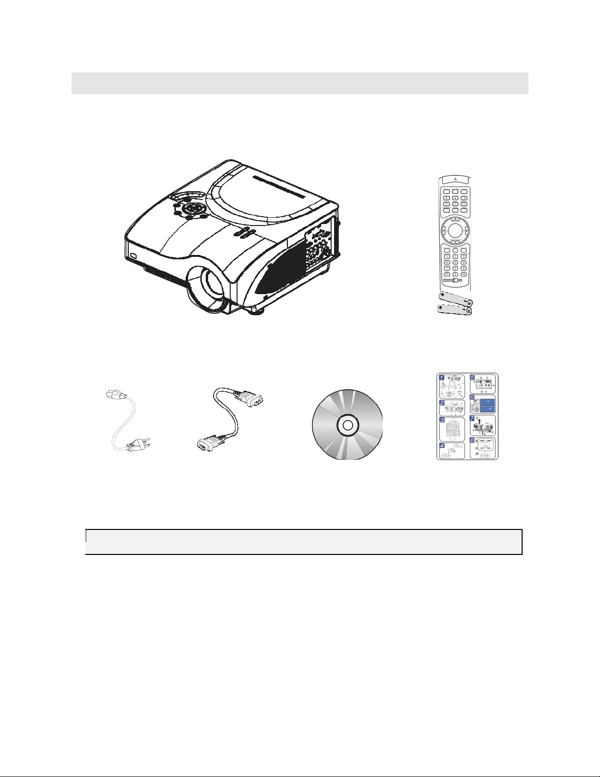
Packing Checklist
Carefully unpack
the
projector and check
PROJECTOR WITH LENS CAP
DLP
G
that the
following
R
items
are included:
ETTING
(
WITH TWO
STARTED
EMOTE CONTROL
AAA
BATTERIES
)
P
OWER CORD
Contact
Caution:
your dealer immediately
Avoid using
C
the
projector in
OMPUTER CABLE
(DB15-DB15)
if
any
items
dusty
environments.
CD-ROM (T
HIS USER’S MANUAL
are missing, appear damaged, or
) Q
if the unit
UICK START GUIDE
does
not work.
Page 9

Page 10
L
LPP
P PP
P
j
jee
e
t
t
U
U
e
e
’
’
D
D
D
o
r
o
r
o
L
r
—
r
c
o
c
t
j
c
s
r
s
—
r
o
U
—
r
o
M
s
r
s
M
’
s
e
r
s
M
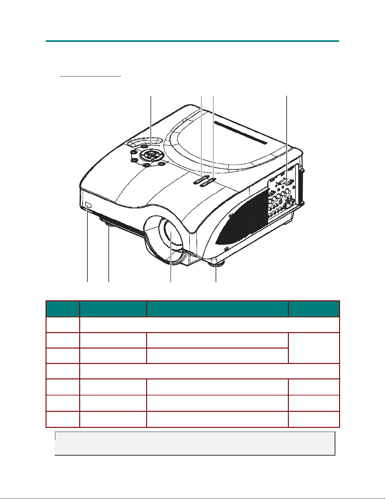
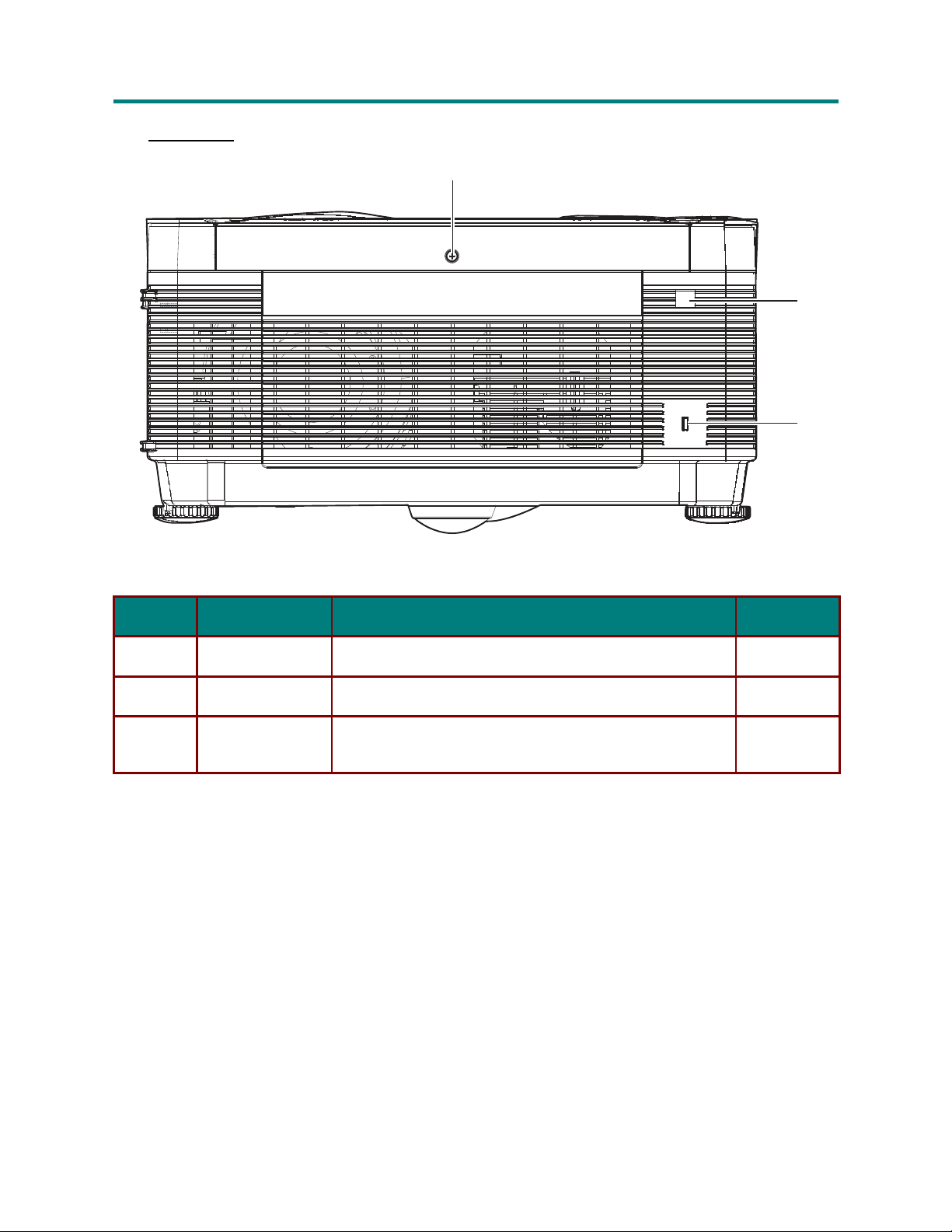
Views of Projector Parts
F ront-right
I
TEM
1.
2.
3.
4.
5.
6.
7.
7
See “Top View—On-screen Display (OSD) Buttons and LEDs” on page 3.
Focus
Lens zoom
See “Side View Connectors” on page 4.
Height-adjusters
Lens
Front IR receiver
View
5
L
ABEL
a
u
n
a
l
a
u
n
a
l
a
u
n
a
l
1
6
2 3
5
D
ESCRIPTION
4
S
EE PAGE
:
Focuses the projected image
Enlarges the projected image
17
Turn to adjust level of projector
Remove lens cap before use
Receiver for IR signal from remo
te
control
16
14
10
Important:
Ventilation
cool.
openings on
Do
not obstruct
the
projector allow
any
of the ventilation
for
good air
openings.
– 2 –
circulation,
which keeps
the
projector lamp
Page 11
L
LPP
P PP
P
j
jee
e
t
t
U
U
e
e
’
’
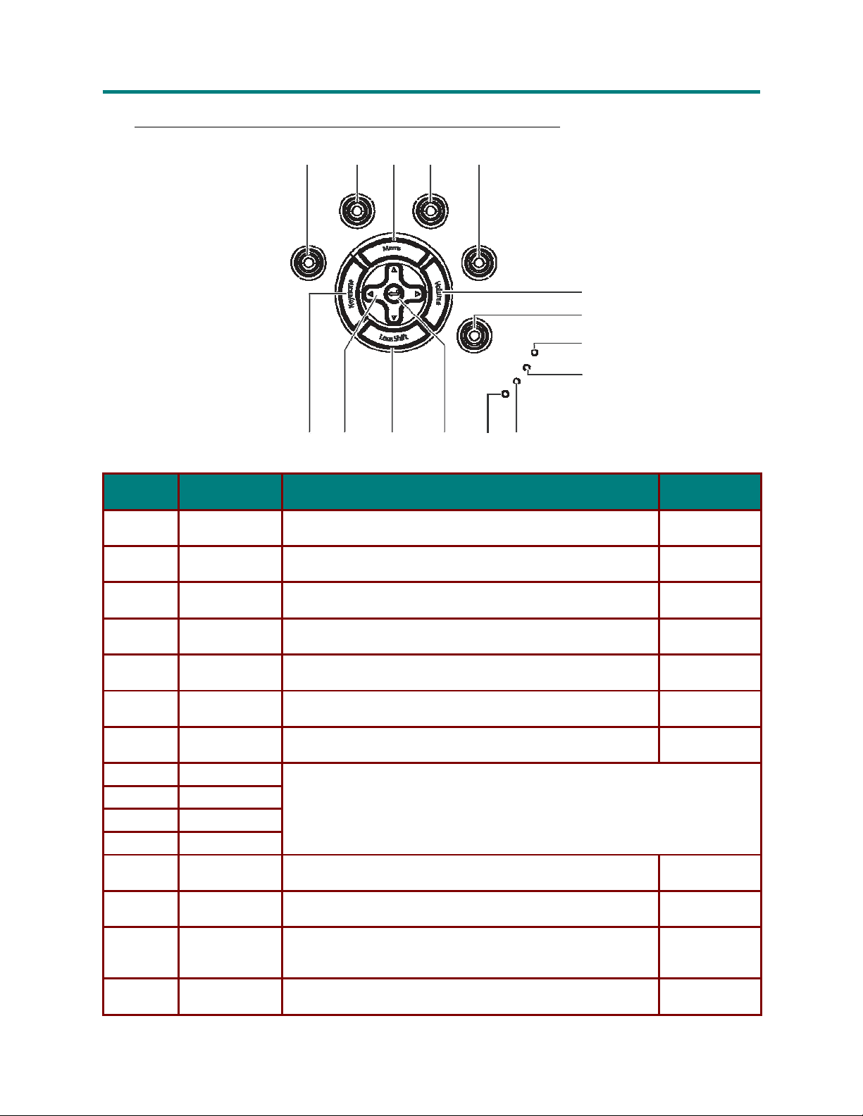
T op View—On-screen Display (OSD) Buttons and LEDs
1 2 3 4 5
P
o
ower
n/off
Auto
Source
Data
I
TEM
1.
2.
3.
4.
5.
6.
7.
8.
9.
10.
11.
12.
13.
14.
15.
Power of/off
Auto
Menu
Source Data
Source Video
Volum
User Mode
Power
Temp
Lamp 1
Lamp 2
Enter
Lens Shift
Arrow buttons
Keystone
L
ABEL
e
15 14 13 12 11 10
D
ESCRIPTION
Turns the projector on or off
Optimizes image size, position, and resolution
Opens and exits the OSD
Detects the data (PC) input device
Detects the video input device
Adjust the volume with LEFT/RIGHT arrow buttons
Open the User mode menu
See “Projector LED Descriptions” on page 5.
Confirm settings in OSD menus
Adjust the vertical shift of the lens
Navigate and changes settings in the OSD
Volum
e
/keystone adjust when OSD off
Adjust the keystone with UP/DOWN arrow buttons
a
u
D
D
D
o
r
r
L
r
r
c
o
–
s
o
r
c
o
o
t
r
j
c
o
r
–
s
r
–
U
s
e
n
a
s
M
s
M
’
r
s
M
l
a
u
n
a
l
a
u
n
a
l
Source
V
ideo
6
Power
emp
7
8
9
S
EE PAGE
14
19
14
:
U
ser
Mode
T
Lamp 1
Lamp 2
– 3 –
Page 12
L
LPP
P PP
P
j
jee
e
t
t
U
U
e
e
’
’
D
D
D
L
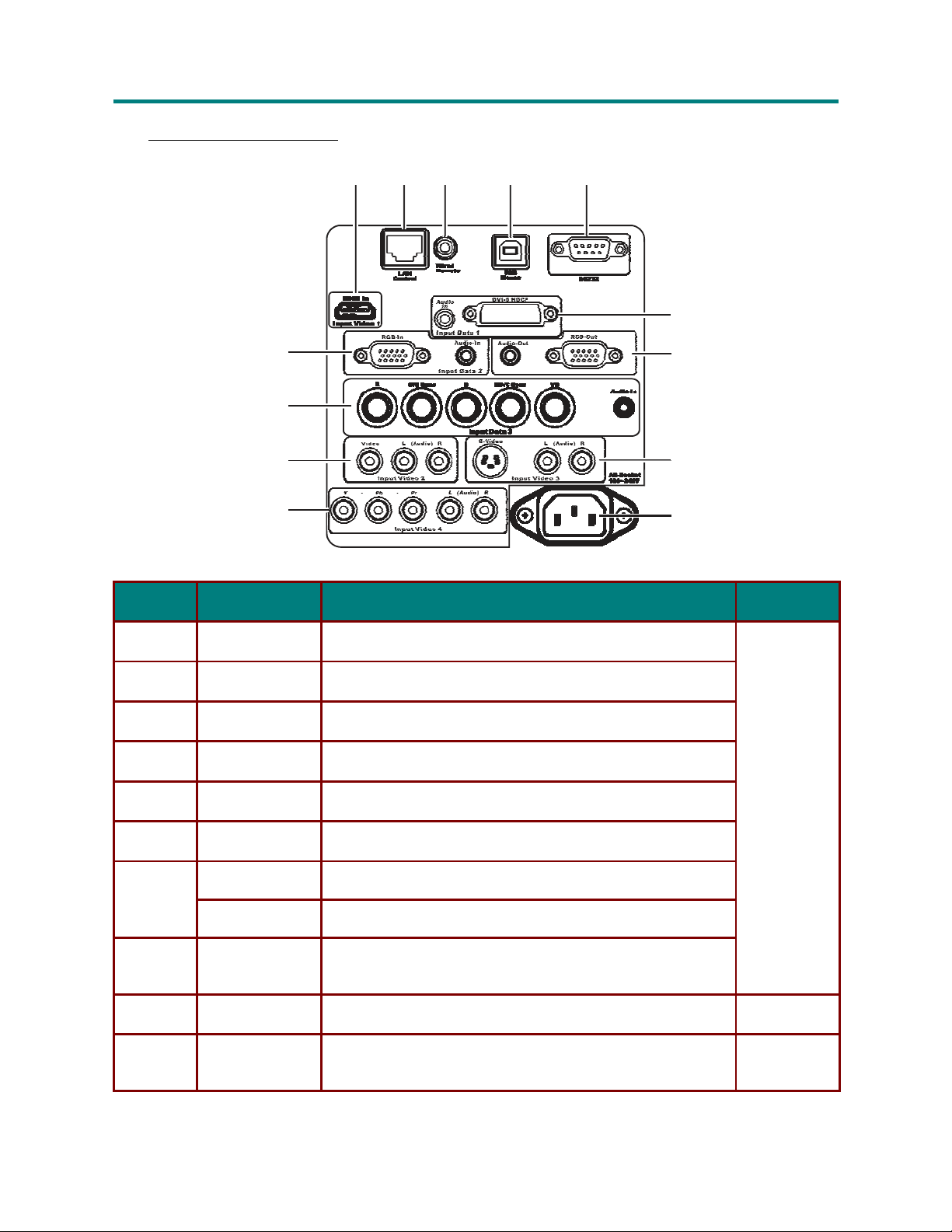
S ide
I
TEM
1.
2.
3.
4.
5.
6.
7.
8.
9.
10.
a
c
c
j
c
View
—
r
o
t
s
—
r
o
s
U
—
r
o
s
Connectors
L
ABEL
e
13
12
11
10
r
s
r
’
r
o
r
o
r
o
r
Input Video 1
LAN Control
Wired Remo
USB Mouse
RS232
Input Data 1
Audio-Out
RGB-Out
Input Video 3
Power
Input Video 4
u
n
a
M
s
M
s
M
l
a
u
n
a
l
a
u
n
a
l
1
2
3
Connect an HDMI cable from an HDTV
Connect
te Connect
Connect the USB cable from
This is
Connect
Connect an audio cable to external speakers
Connect an RGB cable to an external monitor
Connect an S-video cable to the S-video connector
Connect an RCA audio connector to L/R audio connectors
Connect the supplied power cord
Connect an RCA component cable the Y/Pb/Pr connectors
Connect an RCA audio connector to L/R audio connectors
a
LAN cable for controlling projector through
a
wired remo
a
service port for firmware upgrades.
a
DVI-D computer cable from
4
D
ESCRIPTION
te
control
a
computer
5
a
computer
6
7
8
9
S
EE PAGE
PC
a
12
:
14
12
– 4 –
Page 13
L
LPP
P PP
P
j
jee
e
t
t
U
U
e
e
’
’
TEM
I
11.
12.
13.
P rojector LED Descriptions
LED
Power
Temp
Lamp 1
Lamp 2
U
ABEL
L
Input Video 2
Input Data 3
Input Data 2
O
N
System ready
Standby
Standby
Standby
(SEE PAGE
/lamp
/lamp
D
D
D
L
Connect
ESCRIPTION
D
a
composite video cable to the Video connector
Connect an RCA audio connector to L/R audio connectors
Connect
Connect an RGB cable from
Connect an audio cable from
a
5-connector BNC (RGB + VSync + HSync) cable
a
computer to RGB-In
a
computer to Audio-In
14)
off
off
O
Power off
Lamp on
Lamp on
Lamp on
FF
(SEE PAGE
14)
o
r
r
r
r
c
o
o
o
–
r
c
o
–
t
r
j
c
o
–
F
LASHING
System error
Over temperature
Lamp error
Lamp error
(SEE PAGE
U
s
r
s
r
s
e
S
a
s
M
a
s
M
’
r
s
M
EE PAGE
12
45)
a
u
n
l
a
u
n
l
a
u
n
a
l
:
– 5 –
Page 14
L
LPP
P PP
P
j
jee
e
t
t
U
U
e
e
’
’
D
D
D
L
I
TEM
1.
2.
3.
o
r
o
r
o
r
Rear
—
r
c
o
—
r
c
o
U
—
t
r
j
c
o
View
L
ABEL
Cover screw
Rear IR receiver
Security Lock
a
u
n
s
s
s
e
a
r
s
M
r
s
M
’
r
s
M
l
a
u
n
a
l
a
u
n
a
l
1
2
3
Loosen to remove lamp cover
Receiver for IR signal from remo
Secure to permanent object with
system
D
ESCRIPTION
te
control
a
Kensington® Lock
S
EE PAGE
38
10
42
:
– 6 –
Page 15
L
LPP
P PP
P
j
jee
e
t
t
U
U
e
e
’
’
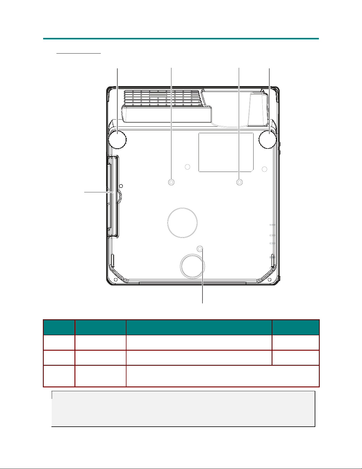
B ottom
I
TEM
1.
2.
3.
View
1
L
ABEL
Carry handle
Height adjusters
Ceiling support
holes
a
u
o
D
D
D
2
3
r
r
L
r
3
r
c
o
–
s
o
r
c
o
o
t
r
j
c
o
r
–
s
2
r
–
U
s
e
n
a
s
M
s
M
’
r
s
M
l
a
u
n
a
l
a
u
n
a
l
3
Unfold to carry projector
Adjust level of projector
D
ESCRIPTION
Contact your dealer for information on mounting the projector on
S
EE PAGE
—
16
a
ceiling.
:
Caution:
For
depth
walls and ceiling.
42
for
ceiling
installations,
of 6 mm (1/4 inch). To
For
permanent
more
information.
use approved mounting hardware and M4 screws
allow
for
proper
ventilation,
installations, follow
– 7 –
keep a distance
local codes.
See
“Ceiling
with a
of 50 cm
maximum screw
Installation” on
(20 inches)
from
page
Page 16
L
LPP
P PP
P
j
jee
e
t
t
U
U
e
e
’
’
D
D
D
o
r
o
r
o
L
r
—
r
c
o
c
t
j
c
s
r
U
s
s
r
s
’
s
e
r
s
—
r
o
—
r
o
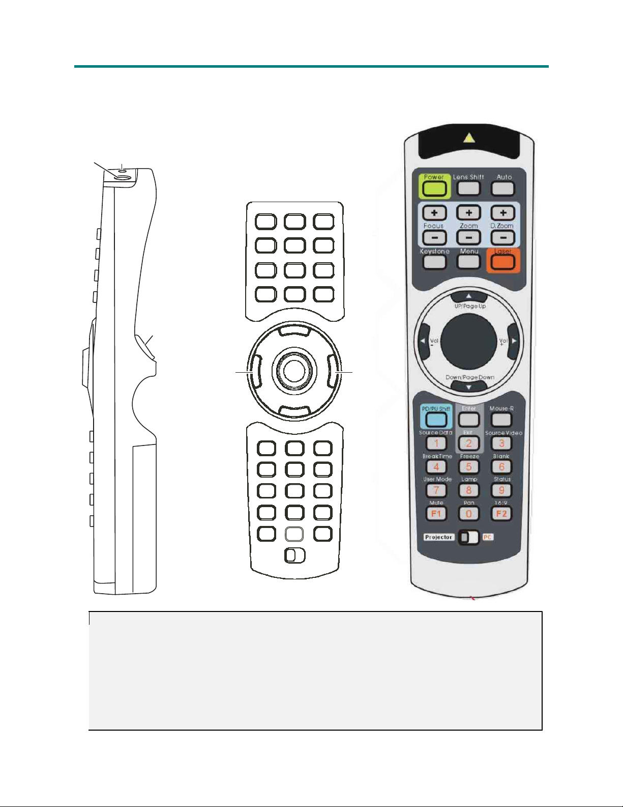
Remote Control Parts
1 2
3
Important:
1.
Avoid using
rescent
2.
Be
tween remote control and
reflective
3.
The buttons
remote
the
the
projector
lights
can disrupt remote control
sure nothing
surfaces such as projector screens.
control. This
obstructs the path
and keys on
M
M
M
l
a
u
n
a
l
a
u
n
a
l
4
7
10
13
17 18 19
21 22 23
24 25 26
27 28 29
30 31 32
33 34 35
with
bright
fluorescent
operation.
between
the
projector is
the
projector have
user’s manual describes
obstructed,
a
u
n
a
5
8
11
14
16
20
36
6
9
12
15
lighting
the
remote control and
you can bounce the signal
the
same
the functions
tu
rned
on.
Certain high-frequency
the projector. If the path
functions as the
based on
off
certain
corresponding
the
remote
control.
fluo-
buttons
be-
on
– 8 –
Page 17

L
LPP
P PP
P
j
jee
e
t
t
U
U
e
e
’
’
a
u
o
D
D
D
TEM
I
1.
2.
IR
W
ABEL
L
Signal
ired Remote
Sends
IR
signal
Connect a cable
to
projector
to the
projector
ESCRIPTION
D
for
wired remote control
r
r
L
r
r
c
o
–
s
o
r
c
o
o
t
r
j
c
o
r
–
s
r
–
U
s
e
n
a
s
M
s
M
’
r
s
M
l
a
u
n
a
l
a
u
n
a
l
3.
4.
5.
6.
7.
8.
9.
10.
11.
12.
13.
14.
15.
Mouse-L
Pow
Lens
Auto
Focus+
Z
D.Z
F
Z
D.Z
Key
Menu
Laser
er
Shift
oom+
oom+
ocus-
oom-
oom-
s
tone
O
Left-mouse
T
urn
Shift the
Automatically
Press
Press
Press
Press
Press
Press
Press
pen and close
Press
button
the
projector on and
lens vertically up or down
to
increase
to
increase
to
increase
to
decrease
to
decrease
to
decrease
to
open
to
use
when connected
off
synchronize video
the
motorized
the
motorized zoom
the
digital zoom
the
motorized
the
motorized zoom
the
digital zoom
the
keys
tone
the On
the
Screen Display
laser pointer
menu
settings
focus
focus
to a PC
(OSD)
16.
17.
18.
19.
20.
21.
22.
23.
24.
25.
26.
Up/Page
Vol-
Mouse pad
Vol+
Down
PD/PU Shift
Enter
Mouse-R
SourceData
Exit Exit OS
SourceVideo
Up
/Page
OS
Down
D selection
Decrease volume, select menu sub
Move
Increase volume, select menu sub
OSD
selection (dow
Enable or disable
Press
to
Right-mouse
Press repeatedly
Press repeatedly
(up), USB up
the
mouse pointer when connected
USB
confirm
settings in OSD
button
to
D (when in main menu), go
to
arrow key when
item
item
n), USB
down arrow key when
page up and page down
when connected
select
data
select video source:
– 9 –
to
source:
to
previous menu (when in child menu)
button 21 LED is
and decrease values
to
a
PC
and increase values
button 21 LED is
function
a
PC
RGB, DVI, RGBHV, W
S-Video,
Component, HDMI
on
ireless
on
Page 18

L
LPP
P PP
P
j
jee
e
t
t
U
U
e
e
’
’
D
D
D
L
TEM
I
27.
28.
29.
a
j
c
o
c
t
c
BreakT
F
Blank
—
r
s
r
—
r
o
s
U
—
r
o
s
e
ABEL
L
ime
reeze
F
s
r
’
r
Put the
o
r
o
r
o
r
u
n
a
M
s
M
s
M
l
a
u
n
a
l
a
u
n
a
l
projector in standby
See
page
35.
reeze
the
Blank
the
onscreen image
display
ESCRIPTION
D
for the time
specified in
the
Service Menu.
UserMode
30.
Lamp
31.
Status O
32.
Mute Mute the
33.
34.
35.
36.
Note:
The
USB
poses
Pan
16:9
Projector PC
remote control can only
cable connection.
only.
Select
O
interface with a
The
user picture mode
pen lamp
pen
Digital pan
O
pen
Swap IR function for PC or Projector
computer cable connects a computer
settings
the
service menu
audio
the
aspect
Remote Control Operating Range
The
remote control uses infrared
remote directly
the
rear
of the projector, the remote
30 degrees above or below
move a
little
closer.
at the projector.
tr
ansmission
Provided you are
will
the
projector
function
level. If the
Projector and Remote Control Buttons
The
projector can be operated using the remote control or
operations can be carried
in
use.
ited
out with the
remote
menu
menu
ratio
computer when connected
to the
to
control
the projector. It is not
not
holding
well within a radius
projector does
the
remote perpendicular
not
the buttons on the top of the projector. All
control;
however
the buttons on the
to the
of
computer through a
projector
about 10 meters (33
respond
for
necessary
to the
projector are lim-
display pur-
to point the
to the
feet)
remote
control,
sides or
and
– 10 –
Page 19

Page 20
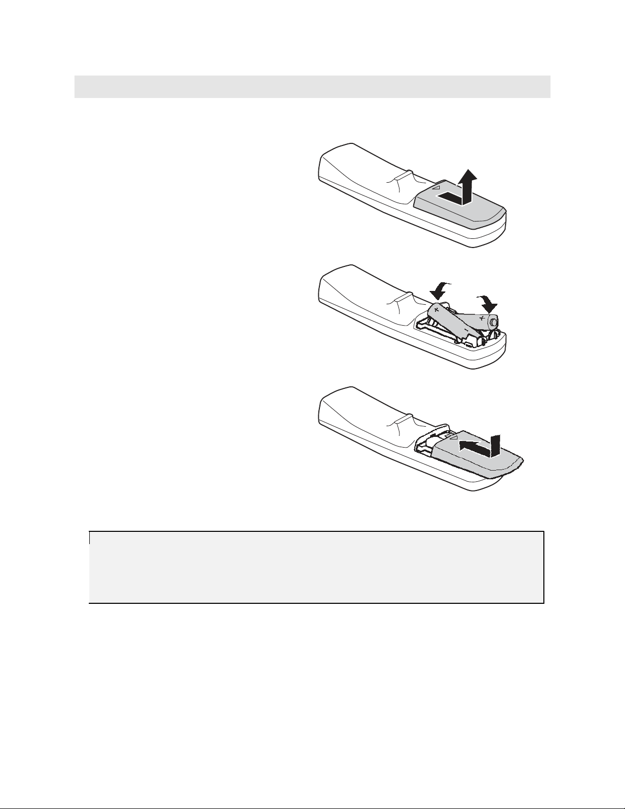
Inserting the Remote Control Batteries
Remove the battery compartment cover by
1.
sliding the cover in the direction of
the arrow.
Insert the supplied batteries taking note
2.
of the polarity (+/-) as shown here.
Replace the cover.
3.
Caution:
1.
Only
use
AAA
alkaline
batteries.
2.
Dispose
of
used
batteries
according
to
local ordinance regulations.
3.
Remove
the batteries
when
not
using
the
projector
S
ETUP AND
for
prolonged periods.
OPERATION
Page 21

Page 22

L
LPP
P PP
P
j
jee
e
t
t
U
U
e
e
’
’
D
D
D
o
r
o
r
o
L
r
—
r
c
o
c
t
j
c
s
r
—
r
o
s
r
U
—
r
o
s
e
r
n
a
s
M
n
a
s
M
’
a
s
M
Connecting Input Devices
A PC or
time.
still
connector.
notebook computer as well as video devices can be connected
Video devices include
cameras. Check
the
user manual
13
12
L
ABEL
11
10
te
I
TEM
1.
2.
3.
4.
5.
6.
7.
8.
9.
Input Video 1
LAN Control
Wired Remo
USB Mouse
RS232
Input Data 1
Audio-Out
RGB-Out
Input Video 3
Power
a
u
l
a
u
l
a
u
n
l
to the
DVD, VCD,
1
Connect an HDMI cable from an HDTV
Connect
Connect
Connect the USB cable from
This is
Connect
Connect an audio cable to external speakers
Connect an RGB cable to an external monitor
and
VHS
play
of the
2
ers, as
connecting device
3
4
well as movie camcorders and digital
to
confirm
5
D
ESCRIPTION
a
LAN cable for controlling projector through
a
wired remo
a
service port for firmware upgrades.
a
DVI computer cable from
te
control
a
computer
a
computer
it
has
Connect an S-video cable to the S-video connector
Connect an RCA audio connector to L/R audio connectors
Connect the supplied power cord
projector
the
6
7
8
9
a
at the
appropriate
PC
same
output
– 12 –
Page 23

L
LPP
P PP
P
j
jee
e
t
t
U
U
e
e
’
’
TEM
I
10.
11.
12.
13.
The
the
Connect a computer
better
Connect a video device
for
Input Video 4
Input Video 2
Input Data 3
Input Data 2
connectors you choose on the projector may depend on available corresponding connectors on
devices you are connecting
signal is as
1. Input Data 1 is a
2. Input Data 3 is an
3. The Input Data 2
a
better
1. Input
2. Input
rior
3. Input
4. Input
Warning:
As a safety precaution,
connections.
D
D
D
L
ABEL
L
Connect an RCA component cable the Y/Pb/Pr connectors
ESCRIPTION
D
Connect an RCA audio connector to L/R audio connectors
Connect
a
composite video cable to the Video connector
Connect an RCA audio connector to L/R audio connectors
to the
follows:
signal is as
Video 1 is a digital signal and
Video 4 uses a component cable (3
analog connection.
Video 3 uses an S-video cable. S-video provides a sharper image
Video 2 uses a composite video (yellow
Connect
generator
Connect
Connect an audio cable from
a
5-connector BNC (RGB + VSync + HSync) cable to
or
advanced video converter.
a
DSUB-15-to-5BNC cable from
a
Connect the supplied DB15-DB15 cable from
Connect an audio cable from
to.
projector through one
digital signal and
analog signal; use a
analog signal uses a standard
to the
projector through one
follows:
disconnect all power
offers the best
DSUB-15-to-5BNC
offers the best
to the
of the Input Data 1/2/3
a
RGB
of the Input
RCA
connectors;
RCA
projector and connecting devices before making
a
computer
computer to Audio-In
computer to Audio-In
connection
connection
connector) connection.
to
cable
(DB15-DB15) computer cable.
Video
1/2/3/4
to
red/
o
r
r
r
r
c
o
o
o
–
r
c
o
–
t
r
j
c
o
–
U
a
computer to RGB-In
connections.
your
computer.
for the
your video device.
green/blue)
The
connection.
connections.
for the most
than
composite video.
s
s
s
r
r
e
r
a
’
order
The
a
s
M
a
s
M
a
s
M
pattern
for
order
a
u
n
l
a
u
n
a
u
n
a
supe-
l
l
– 13 –
Page 24

L
LPP
P PP
P
j
jee
e
t
t
U
U
e
e
’
’
D
D
D
o
r
o
r
o
L
r
—
r
c
o
c
t
j
c
s
r
U
s
s
r
s
’
s
e
r
s
—
r
o
—
r
o
M
M
M
a
u
n
a
l
a
u
n
a
l
a
u
n
a
l
Starting and Shutting down the Projector
Connect the power cord to the projector.
1.
Connect the other end to
The Power LED on the projector turns on.
Turn on the connected devices.
2.
a
wall outlet.
Ensure the Power LED is on (not flashing)
3.
and then press the
the projector.
(If any LEDs are flashing, do not press the
Power
button. See “LED Error Messages”
on
page 45.)
button to turn on
Power
The projector splash screen displays and
connected
If the connected device is
appropriate
board
projector. (Check the user manual of the
PC to determine the appropriate Fn key
combination
If more than one input device is con-
4.
nected,
buttons repeatedly to switch among devices.
devices are detected.
a
PC, press the
keys on the computer key-
to
switch the display output to the
to
change display output.)
press the
Source Data/Video
Press Source Data to switch among
computer connected to Computer,
RGBHV,
Press Source Video to switch among
video device connected to Video, S-Video,
Component,
WPC (wireless), or Digital.
or
HDMI.
a
a
– 14 –
Page 25

L
LPP
P PP
P
j
jee
e
t
t
U
U
e
e
’
’
To turn off the projector, press the
5.
button. The projector prepares for shutdown
and
a
“Wait
message appears.
Caution:
Do
not
unplug
the
power cord
a
moment please…”
until
all
Power
the LEDs
are
on,
When the “Power Off?/Press Power again”
6.
message
The
indicating
o
D
D
D
the
r
r
L
r
appears, press the Power button.
projector turns off.
proj
ector
r
c
o
o
o
–
r
c
o
–
t
r
j
c
o
–
U
has cooled down.
s
r
s
r
s
e
a
u
n
a
s
M
s
M
’
r
s
M
l
a
u
n
a
l
a
u
n
a
l
– 15 –
Page 26

L
LPP
P PP
P
j
jee
e
t
t
U
U
e
e
’
’
D
D
D
o
r
o
r
o
L
r
—
r
c
o
c
t
j
c
s
r
U
s
s
r
s
’
s
e
r
s
—
r
o
—
r
o
M
M
M
a
u
n
a
l
a
u
n
a
l
a
u
n
a
l
Adjusting the Projector Level
Take note of the
•
•
•
The projector table or stand should be level and sturdy
Position the projector so that it is perpendicular to the screen.
Be sure cables are not in the way or can not cause the projector to be knocked over
following when
A
setting up the projector:
.
.
B
B
C
C
1.
To raise the level of the projector,
.
adjusters
The height adjusters drop down [C].
[B]
lift
the projector [A] and rotate the height-
2.
To lower the level of the projector, rotate the height adjusters in the opposite direc-
tion.
– 16 –
Page 27

L
LPP
P PP
P
j
jee
e
t
t
U
U
e
e
’
’
Adjusting the Zoom, Focus and Keystone
1.
Use the
to
age and screen size.
A display pattern appears
on
the
window;
projected
the
Use the Focus +/- control
2.
to
image.
A display pattern appears
on
the
Zoom +/-
resize the projected im-
the screen to indicate
border of the display
adjust until the
image matches
display-pattern border.
sharpen the projected
the screen; adjust until
cross-hair is sharp.
control
D
D
D
a
u
o
r
r
L
r
r
c
o
–
s
o
r
c
o
o
t
r
j
c
o
r
–
s
r
–
U
s
e
n
a
s
M
s
M
’
r
s
M
l
a
u
n
a
l
a
u
n
a
l
Use the Keystone +/- but-
3.
tons to correct image
distortion.
– 17 –
Page 28

L
LPP
P PP
P
j
jee
e
t
t
U
U
e
e
’
’
D
D
D
o
r
o
r
o
L
r
—
r
c
o
c
t
j
c
s
r
U
s
s
r
s
’
s
e
r
s
—
r
o
—
r
o
Adjusting the Volume
Press the
1.
ton.
The volume control appears
Use the Volume +/- but-
2.
tons
level.
Press the Mute button to
3.
turn
Volume +/-
on
the display.
to
adjust the volum
off the volume.
M
M
M
a
a
n
n
n
a
but-
a
u
l
a
u
l
a
u
l
e
– 18 –
Page 29

Page 30

ON-S
OSD Menu Controls
The
projector has an
Navigating the OSD
You
can use
and make changes
sponds
1. To
button.
2.
Press
through
3.
Press
up
4.
Press
tings.
5.
Press
or leave a submenu.
the
remote control cursor
open
the OSD,
the
the
the
to
Menu
Enter
Keystone Menu Laser
PD/PU Shift Enter Mouse-R
cursor
menus.
cursor
change values
to
to the
and down in a menu.
CREEN
DISPLAY
OSD that lets
you make image adjustments and change various
buttons or the buttons on the top of the
to the OSD. The button
button on the
Up/Page Up
Vol Vol
Down/Page Down
press
button to
button to
close
the OSD
the
for set-
remote
Menu
move
move
control.
(OSD) M
in
the
center
ENU
SETTINGS
of the
proj
ector
settings.
projector
cursor
buttons
to
navigate
corre-
Page 31

Page 32

L
LPP
P PP
P
j
jee
e
t
t
U
U
e
e
’
’
D
D
D
o
r
o
r
o
L
r
—
r
c
o
c
t
j
c
s
r
U
s
s
r
’
s
e
r
—
r
o
—
r
o
u
n
a
M
u
n
a
s
M
n
a
s
M
Setting the OSD Language
You
may
want to
to
guage
your preference before
1.
Press the Menu button. The Picture menu appears.
reference
the OSD on
a
l
a
l
a
u
l
conti
your projec
nuing.
(The default
tor
while reading
language is
this section. Set the OSD
English.)
lan-
2.
Press the cursor button until Setup is highlighted.
3.
Press the cursor button to highlight Language.
4.
Press the cursor button until the language you want is highlighted.
5.
Press the
Menu
button twice to close the OSD.
– 20 –
Page 33

L
LPP
P PP
P
j
jee
e
t
t
U
U
e
e
’
’
Picture Menu
Press
the
menu. Press
values
for settings.
Menu
the
button to
cursor
open
button to
OSD
the
menu. Press
move up and down in
the
D
D
D
L
cursor
button to
Picture
the
o
r
r
r
menu. Press
r
c
o
o
r
c
o
o
t
r
j
c
o
move
–
s
r
s
s
s
r
e
r
M
s
’
s
Picture
–
–
U
to the
to
u
n
a
u
n
a
M
u
n
a
M
change
a
l
a
l
a
l
User mode
Brightness
Contrast
Sharpness
Saturation
Tint
Gamm
I
TEM
Press the cursor
Memory
2;
and Memory 3.
button to choose from three user modes: Memory 1;
D
ESCRIPTION
D
EFAULT
—
Any settings you change in the Picture menu are saved in Memory that you
have
selected.
Press the cursor
Press the cursor
Press the cursor
Press the cursor
Press the cursor
a
Press the cursor
Input
PC
MAC
Video
Chart
B&W
button to adjust the brightness. (Range: 0 – 100)
button to adjust the contrast. (Range: 0 – 100)
button to adjust the display sharpness (Range: 0 – 100)
button to adjust the video saturation. (Range: 0 – 100)
button to adjust the video tint/hue. (Range: 0 – 100)
button to adjust the gamma correction of the display.
Gamma
2.2
1.8
2.4
2.2
2.4
Brightness
High
High
Low
Low
High
Computer,
5BC,
Digital
50
50
50
50
50
PC:
Video:
Video,
S-Video,
Component,
HDMI
– 21 –
Page 34

L
LPP
P PP
P
j
jee
e
t
t
U
U
e
e
’
’
r
D
D
D
r
r
L
TEM
I
Color Temp
Color Space
Video form
Color balance
Red/Green/
Blue
Fleshtone
Film mode
3D Comb
Filter
White
peaking
Reset
o
o
o
r
—
r
c
o
c
t
j
c
s
—
r
o
s
U
—
r
o
s
e
Press the cursor
Range:
High brightness mode
Preset mode
Custom
Press the cursor
(Range: RGB – YCbCr – YpbPr – SMPTE240M – Blue only)
at Press the cursor
(Range: Auto – NTSC 50Hz 3.58MHz – NTSC 60Hz 3.58MHz – NTSC
60Hz 4.43MHz – PAL 50Hz 4.43MHz – PAL 60Hz 3.58MHz – PAL 50Hz
3.58MHz – PAL 60Hz 4.43MHz – SECAM50Hz 4.43MHz)
Press the cursor
(Range:
Skin colors can become corrupted during the broadcast process. Use this setting
to
Press the cursor
Film is
fps (frame per second, i.e., full-motion video). The projector can convert
film source to progressive video
fps with PAL50Hz and SECAM. The result is high-definition play back.
Press the cursor
This technique provides near perfect Y/C separation for
Press the cursor
White Peaking increases the output in the brightest whites without changing
the
blacks and dark grays. It crushes the whites slightly, but
to clip them or seriously obscure white detail. If you prefer
image, adjust toward the maximum setting. For
age,
Press the cursor
Resets
a
u
n
a
r
s
M
r
s
M
’
r
s
M
l
a
u
n
a
l
a
u
n
a
l
ESCRIPTION
D
button to adjust the color temperature.
6400K, CT x = 0.3; CT y = 0.33
mode
Will
0 –
100)
correct skin color as desired.
a
digital video recording with the original recording encoded
From 5000K to 12000K (increments of 100K)
update when hardware is available.
button to adjust the color space.
button to adjust the video format.
button to adjust the red/green/blue color balance.
button to adjust the Fleshtone. (Range: 0 – 100)
at 60
fps with NTSC and PAL60Hz or
button to enable or disable Film mode.
still
button to enable or disable 3D Comb Filter.
a
smoother, more natural im-
adjust toward the minimum setting.
button to adjust the White Peaking. (Range: 0 – 10)
all
Picture settings to default values
images.
it
does not ap- pea
a
stronger
at 24
at 50
EFAULT
D
High-
brightness
RGB:
Computer,
5BNC,
DVI
YCbCr:
DVI
Auto
50
50
On
On
10
—
– 22 –
Page 35

L
LPP
P PP
P
j
jee
e
t
t
U
U
e
e
’
’
P icture Menu Functions Available for Connected Source
Function
Computer
RGBHV
WPC
Digital
Component
D
D
D
L
r
r
r
Composite
a
u
o
r
c
o
–
s
o
r
c
o
o
t
r
j
c
o
–
–
s
U
s
S-Video
r
r
e
n
a
s
M
s
M
’
r
s
M
n
a
a
HDMI
l
a
u
l
a
u
n
l
value
value
format
mode
correction
Brightness
Contrast
Sharpness
Saturation
Tint
Gamma
Color Temp
CT x
CT y
Color space
Video
Color Balance
Red/Green/Blue
Flesh tone
Film
x
x
x
x
x
x
x
x
x
x
x
x
x
x
x
x
x
x
x
x
x
x
x
x
x
x
x
x
x
x
x
x
x
x
x
x
x
x
x
x
x
x
x
x
x
x
x
x
x
x
x
x
x
x
x
x
x
x
x
x
x
x
x
x
x
x
x
x
x
x
x
x
x
x
x
x
x
x
x
x
x
x
x
x
x
x
x
x
x
x
x
x
x
x
x
x
3D Comb
White
Reset
Peaking
x
=
Filter
available
to
video source
x
x
x
x
x
x
x
x
x
x
x
x
x
x
x
x
x
– 23 –
Page 36

L
LPP
P PP
P
j
jee
e
t
t
U
U
e
e
’
’
D
D
D
o
r
o
r
o
L
r
—
r
c
o
r
c
o
t
r
j
c
o
Advance Menu
Press
menu. Press
values
Menu
the
for settings.
—
—
the
s
r
s
r
U
’
s
e
r
button to
cursor
a
u
n
a
s
M
s
M
s
M
l
a
u
n
a
l
a
u
n
a
l
open
the
button to
OSD
menu. Press
move up and down in
the
cursor
button to
Advance
the
move
menu. Press
to the
Advance
to
change
Frequency
Phase
H size
V size
Overscan
Horizontal
Position
Vertical
Position
I
TEM
Press the cursor
(Range:
Press the cursor
(Range:
Press the cursor
(Range:
Press the cursor
(Range:
Use overscan to trim an unwanted blank border from the onscreen image.
0° -
0° -
0 –
0 –
100°)
100°)
100)
100)
button to adjust the A/D sampling number.
button to adjust the A/D sampling phase.
button to adjust the size of the display horizontally.
button to adjust the size of the display vertically.
D
ESCRIPTION
Press the cursor
(Range:
0% –
10%)
button to adjust video overscan.
D
EFAULT
Auto
detected
Auto
detected
50
50
3%:
composite,
S-video,
component
0%:
5BNC, DVI,
HDMI,
Press the cursor
button to move the image
left or
right. (Range: 0 – 100)
Wireless
50
Press the cursor
button to move the image up or down. (Range: 0 – 100)
50
– 24 –
Page 37

L
LPP
P PP
P
j
jee
e
t
t
U
U
e
e
’
’
TEM
I
Aspect Ratio
D
D
D
L
Press the cursor
1:1 – Native size, no scaling
4:3 – Standard TV form
16:9 – High Definition TV (HDTV) form
2.35:1 – Anamorphic form
button to adjust the video aspect ratio.
at
ESCRIPTION
D
at
at
(Anamorphic form
at ma
ximizes the resolution on
wide screen TVs as well as standard TVs that support the anamorphic mode.)
o
r
r
r
r
c
o
–
s
o
r
c
o
o
t
r
j
c
o
r
–
s
r
–
U
s
e
s
M
s
M
’
r
s
M
EFAULT
D
4:3
n
a
l
a
u
n
a
l
a
u
n
a
l
a
u
Blank color
Auto sync
Auto search
Freeze
fram
e
Video AGC
Black level
Press the cursor
instead
of
Press Enter to auto tune the
position.
Press the cursor
devices.
button to select
the default logo.
tim
ing phase, frequency, and horizontal/vertical
button to enable or disable auto search for connected
When disabled, you have to manually select the source.
Freeze frame allows you to pause onscreen video.
Press the cursor
Press the cursor
the
autom
video
Press the cursor
(Range:
standard.
On =
button to enable or disable Freeze frame.
button to enable or disable Video AGC. When enabled,
atic
gain control for the video source is auto adjusted to match the
button to enable or disable the 7.5 setup for NTSC.
7.5 IRE; Off = 0 IRE)
a
background color for the blank screen
NTSC uses 7.5 IRE except for Japan which uses 0 IRE. Set Black level to
for use in Japan only.
Off
Digital
zoom
Reset
A dvance Menu Functions Available for Connected Source
Function
Press the cursor
Digital zoom is not available when you are using PIP.
Note:
Resets
all items in
Computer
RGBHV
button to adjust the digital zoom. (Range: 0 – 23)
the Advance menu to default values
WPC
Digital
Component
Logo
—
On
On
On
On
0
U
Composite
S-Video
—
HDMI
Phase
Frequency
H position
V
position
Aspect Ratio
H size
V
size
x
x
x
x
x
x
x
x
x
x
x
x
x
x
x
x
x
x
x
x
x
– 25 –
x
x
x
x
x
x
x
x
x
x
x
x
x
x
x
x
x
x
x
x
x
x
x
Page 38

L
LPP
P PP
P
j
jee
e
t
t
U
U
e
e
’
’
D
D
D
L
Function
a
o
r
o
r
o
r
—
r
c
o
c
t
j
c
s
r
U
s
s
s
r
’
e
r
Computer
—
r
o
—
r
o
u
n
a
M
s
M
s
M
a
a
u
n
n
l
a
l
a
u
l
RGBHV
WPC
Digital
Component
Composite
S-Video
HDMI
Overscan
Auto
sync
Auto
search
Freeze frame
Blank color
Video
AGC
Black
level
Digital zoom
Reset
x
=
available
x
x
x
x
x
x
x
x
x
x
x
x
x
x
x
x
x
x
to
video source
x
x
x
x
x
x
x
x
x
x
x
x
x
x
x
x
x
x
x
x
x
x
x
x
x
x
x
x
x
x
x
x
x
x
x
– 26 –
Page 39

L
LPP
P PP
P
j
jee
e
t
t
U
U
e
e
’
’
Setup Menu
Press
the
menu. Press
values
for settings.
Menu
the
button to
cursor
open
button to
Main
the
menu. Press
move up and down in
the
D
D
D
L
cursor
button to
Setup
the
menu. Press
o
r
r
r
r
c
o
–
s
o
r
c
o
o
t
r
j
c
o
move
r
–
s
r
–
U
s
e
to the
to
s
M
s
M
’
r
s
M
Setup
change
n
a
l
a
u
n
a
l
a
u
n
a
l
a
u
Language
Projection
Lens shift
Motorized
focus
I
TEM
front
Press the cursor
English, French, German, Italian, Spanish, Swedish, Chinese Simplified,
Chinese
Press the cursor
button to choose from the following languages:
Traditional, Japanese, Korean, Portuguese, and Russian.
button to choose from four projection methods:
D
ESCRIPTION
D
EFAULT
English
Desktop
Desktop mount, front of screen
Desktop mount, rear of screen
Ceiling mount, front of screen
Ceiling mount, rear of screen
Press Enter to
Press the up/down/left/right cursor buttons to shift the lens vertically and
horizontally.
Press the cursor
activate
lens shift. The following screen appears.
button to adjust the motorized focus.
—
—
– 27 –
Page 40

L
LPP
P PP
P
j
jee
e
t
t
U
U
e
e
’
’
D
D
D
L
Motorized
zoom
H keystone
V keystone
TEM
I
o
r
o
r
o
r
—
r
c
o
c
t
j
c
s
r
U
s
s
r
s
’
s
e
r
s
—
r
o
—
r
o
Press the cursor
Press the cursor
image.
(Range: -100 – +100)
Press the cursor
image.
(Range: -100 – +100)
M
M
M
a
u
n
a
l
a
u
n
a
l
a
u
n
a
l
ESCRIPTION
D
button to adjust the motorized zoom.
button to correct horizontal distortion of the projected
button to correct vertical distortion of the projected
Lamp control—Press the cursor button to display the hidden Lamp control submenu.
Mode
Lamp 1
Press the cursor
Dual
lamp uses both lamps in the projector. Single lamp uses the lamp
which has been used the least.
Press the cursor
button to toggle between Dual lamp and Single lamp.
button to toggle between ECO mode and Norm
mode. Eco mode uses less power and extends lamp life, but decreases lamp
Lamp 2
brightness.
Press the cursor
button to toggle between ECO mode and Norm
mode. Eco mode uses less power and extends lamp life, but decreases lamp
brightness.
OSD settings—Press the cursor button to display the hidden OSD settings submenu.
Position
Transparency
Timeout(sec)
Message
Menu type
Press the cursor
(Range:
Press the cursor
(Range:
Press the cursor
(Range:
Press the cursor
the
bottom-right corner of the screen.
Press the cursor
mode. In Expert mode
button to position the OSD on screen.
Left – Right – Center – Down – Up)
button to set menu screen translucency.
0 –
100)
button to determine the
Always on – 100 seconds)
button to show or hide the OSD information screen in
button to toggle between Expert mode and Norm
all
settings are available in the OSD.
tim
eout delay of the OSD.
Logo settings—Press the cursor button to display the hidden Logo settings submenu.
Logo display
Logo select
Press
to enable or disable if the logo displays when the projector
starts,
and when no source is detected. (Range: On—Off)
Press
to select
tion
you must capture an image with the following “Logo capture”
function.
a
different image for the logo display. To use this func-
D
EFAULT
—
0
0
Dual lamp
al
al
Norm
Norm
al
al
Center
50
20
On
Expert
al
On
Default
(preset
image)
– 28 –
Page 41

L
LPP
P PP
P
j
jee
e
t
t
U
U
e
e
’
’
TEM
I
Logo capture
Press Enter to capture the current display image as the logo. The following
screen
appears:
ESCRIPTION
D
Logo capture is only available for Computer, RGBHV, and DVI input.
Fan control
Press the cursor
fan
speeds.
button to toggle between Norm
Set Fan control to High in altitudes over 3,000 meters (10,000 feet).
Reset
S etup Menu Functions Available for Connected Source
Function
Resets
all items in
Computer
the Setup menu to default values
RGBHV
WPC
Digital
Component
D
D
D
al
and High altitude
r
r
L
Composite
o
r
c
o
–
s
o
r
c
o
o
t
r
r
j
c
o
r
–
s
r
–
U
s
e
D
s
M
s
M
’
r
s
M
EFAULT
—
n
a
l
a
u
n
a
l
a
u
n
a
l
a
u
Norm
al
S-Video
HDMI
Language
Projection
Lens
Motorized
Motorized zoom
H keystone
V
keystone
Lamp mode
Lamp mode
(Lamp1)
Lamp mode
(Lamp2)
OSD
OSD
OSD timeout
Menu
shift
focus
position
translucency
type
x
x
x
x
x
x
x
x
x
x
x
x
x
x
x
x
x
x
x
x
x
x
x
x
x
x
x
x
x
x
x
x
x
x
x
x
x
x
X
x
x
x
x
x
x
x
x
x
x
x
x
x
x
x
x
x
x
x
x
x
x
x
x
x
x
x
x
x
x
x
x
x
x
x
x
x
x
x
x
x
x
x
x
x
x
x
x
x
x
x
x
x
x
x
x
x
x
x
x
x
x
x
x
x
x
x
x
x
x
x
x
x
– 29 –
Page 42

L
LPP
P PP
P
j
jee
e
t
t
U
U
e
e
’
’
D
D
D
L
Function
a
o
r
o
r
o
r
—
r
c
o
c
t
j
c
s
r
U
s
s
s
r
’
e
r
Computer
—
r
o
—
r
o
u
n
a
M
s
M
s
M
a
a
u
n
n
l
a
l
a
u
l
RGBHV
WPC
Digital
Component
Composite
S-Video
HDMI
Logo display
Logo select
Logo capture
Fan
control
Reset
x
=
available
to
video source
x
x
x
x
x
x
x
x
x
x
x
x
x
x
x
x
x
x
x
x
x
x
x
x
x
x
x
x
x
x
x
x
x
x
x
x
x
x
x
x
– 30 –
Page 43

L
LPP
P PP
P
j
jee
e
t
t
U
U
e
e
’
’
Audio Menu
Press
the
menu. Press
values
for settings.
Menu
the
button to
cursor
open
button to
Main
the
menu. Press
move up and down in
the
D
D
D
L
cursor
button to
Audio
the
menu. Press
o
r
r
r
r
c
o
–
s
o
r
c
o
o
t
r
j
c
o
move
r
–
s
r
–
U
s
e
to the
to
s
M
s
M
’
r
s
M
Audio
change
n
a
l
a
u
n
a
l
a
u
n
a
l
a
u
I
TEM
Volum
Treble
Bass
Balance
Mute
Reset
A udio Menu Functions Available for Connecte d Source
Function
Volume
Treble
Bass
e
Press the cursor
Press the cursor
Press the cursor
Press the cursor
Press the cursor
Resets
all items in
Computer
x
x
x
button to adjust the audio volume level. (Range: 0 - 100)
button to adjust the audio treble level. (Range: 0 - 100)
button to adjust the audio bass level. (Range: 0 - 100)
button to adjust the audio volume level. (Range: -50 - +50)
button to enable or disable mute.
the Audio menu to default values
RGBHV
x
x
x
D
ESCRIPTION
WPC
x
x
x
Digital
x
x
x
Component
D
EFAULT
U
Composite
x
x
x
S-Video
x
x
x
x
x
x
50
50
50
0
Off
—
HDMI
x
x
x
x
=
available
to
video source
x
x
x
x
x
x
x
x
x
– 31 –
x
x
x
x
x
x
x
x
x
x
x
x
x
x
x
Balance
Mute
Reset
Page 44

L
LPP
P PP
P
j
jee
e
t
t
U
U
e
e
’
’
D
D
D
o
r
r
L
r
r
c
o
o
r
c
o
o
t
r
j
c
o
Window Menu
PIP (Picture In Picture)
For
example, while displaying
video
source.
as
POP.
to
Press
menu. Press
values
Menu
the
for settings.
—
—
—
the
You
s
r
s
M
s
r
s
U
M
’
s
e
r
s
M
can also have
button to
cursor
a
u
n
a
l
a
u
n
a
l
a
u
n
a
l
mode allows you
output from
the
active windows display side-by-side, which is sometimes re- ferred
open
button to
Main
the
move up and down in
to
view a small video window in a full-screen video display.
your
PC
you could have a small window displaying your
menu. Press
the
cursor
button to
Window
the
move
menu. Press
to the
to
Window
change
Display window
Main window
source
PIP/POP source
PIP H position
PIP V position
I
TEM
Press the cursor
window);
windows
PIP (Picture In Picture); Side by side (POP, two equal-sized
beside each other)
D
ESCRIPTION
button to choose from three settings: Single (one
D
EFAULT
Single
Note: When Single is selected only the Main window source
available.
Press the cursor
window.
Press the cursor
window.
Press the cursor
(Range:
Note: This
Press the cursor
(Range:
Note: This
0 –
item is
0 –
item is
button to choose the input device for the main
button to choose the input device for the second
button to adjust the PIP window horizontally.
100)
not available for Side by side mode.
button to adjust the PIP window vertically.
100)
not available for Side by side mode.
item
is
Last
selected
Last
selected
0
0
– 32 –
Page 45

L
LPP
P PP
P
j
jee
e
t
t
U
U
e
e
’
’
PIP size
TEM
I
o
D
D
D
Press the cursor
button to adjust the size of the PIP window. (Range:
20 – 100, depending on the
Note: This
item is
not available for Side by side mode.
ESCRIPTION
D
tim
ing resolution of the main win- dow)
r
r
L
r
r
c
o
–
s
o
r
c
o
o
t
r
j
c
o
r
–
s
r
–
U
s
e
s
M
s
M
’
r
s
EFAULT
D
M
a
a
20
n
l
a
u
n
l
a
u
n
a
l
a
u
Source
PIP alpha blend
Reset
Press
to swap the current sources for the active windows.
Enter
PIP alpha blend allows you to adjust translucency between the main
window
and the PIP window.
Press the cursor
(Range:
Resets
0 –
all items in
button to adjust the PIP alpha blend.
100)
the Window menu to default values
—
0
—
– 33 –
Page 46

L
LPP
P PP
P
j
jee
e
t
t
U
U
e
e
’
’
D
D
D
o
r
o
r
o
L
r
—
r
c
o
—
r
c
o
—
t
r
j
c
o
ColorMgr Menu
Press
orMgr
change values
Menu
the
menu. Press
Note:
This
menu is
not
r
r
r
the
’
s
s
s
M
M
M
cursor
a
l
a
u
n
a
l
a
u
n
a
l
open
the
button to
Main
s
s
U
s
e
button to
for settings.
available when ColorTemp is
a
u
n
menu. Press
move up and down in
set to
the
High-brightness.
cursor
button to
ColorMgr
the
move
to the
menu. Press
Col-
to
Color select
Lightness
Chrom
Hue
Reset
I
TEM
a
Press the cursor
Chroma,
(Range:
Press the cursor
(Range:
0 –
Press the cursor
(Range:
0 –
Press the cursor
(Range:
Resets
0 –
all items in
button to select
and Hue settings to adjust each color as desired.
red, green, blue, cyan, magenta, yellow)
button to adjust the lightness of the selected color.
100)
button to adjust the saturation of the selected color.
100)
button to adjust the
360)
the ColorMgr menu to default values
D
ESCRIPTION
a
color. Use the Lightness,
tint of
the selected color.
D
EFAULT
50
100
180
—
– 34 –
Page 47

L
LPP
P PP
P
j
jee
e
t
t
U
U
e
e
’
’
Service Menu
Press
menu. Press
values
Menu
the
for settings.
the
button to
cursor
open
button to
Main
the
menu. Press
move up and down in
the
D
D
D
L
cursor
button to
Service
the
o
r
r
r
menu. Press
r
c
o
o
r
c
o
o
t
r
j
c
o
move
–
s
r
–
–
s
s
r
s
’
U
s
e
r
s
to the
to
a
u
n
a
M
a
u
n
a
M
u
n
a
M
Service
change
l
l
a
l
I
TEM
Video information
Ser
ial
number
Software version
Lamp1 hours
Lamp2 hours
Auto power off
Break
time
D
ESCRIPTION
Displays the resolution and refresh rate for RGB/DVI mode.
Displays
Displays the serial number.
Displays information about the firmware version.
Press th
in use for ECO and Norm
Press th
in use for ECO and Norm
Press
specified
Set the length of
time
break
the color standard for video mode.
e c
ursor button to see the number of hours Lamp 1 has been
al
mode.
e c
ursor button to see the number of hours Lamp 2 has been
al
mode.
to enable or disable autom
time of
button on the remo
time
inactivity. (Range: Off; 5 – 60 minutes)
time
the projector goes into standby when the Break
te
control is pressed. While in standby, the
displays on the screen.
atic
shut-down of lamp after the
Press the cursor
(Range:
0 –
Serial control—Press the cursor button to display the hidden Serial control submenu.
Baud rate
Press the cursor
nector.
button to adjust the Break
180 minutes)
button to choose
tim
e.
a
baud rate for the RS232 con-
D
EFAULT
These
items
are
display
only.
5 minutes
0
9600bps
– 35 –
Page 48

L
LPP
P PP
P
j
jee
e
t
t
U
U
e
e
’
’
D
D
D
L
Parity
j
TEM
I
—
r
c
o
c
t
c
s
r
U
s
s
r
s
’
s
e
r
s
—
r
o
—
r
o
Press the cursor
o
r
o
r
o
r
connector.
M
M
M
a
u
n
a
l
a
u
n
a
l
a
u
n
a
l
ESCRIPTION
D
button to choose the parity setting for the RS232
Password—Press the cursor button to display the hidden Password submenu.
Password enable
Press the cursor
button to enable or disable
Set Password
Change Password
Lamp hours reset
Reset
When you enable the password,
[000000]. Use the remo
When enabled, settings in the
word.
changed.
To s
et a
password, press th
te
the cursor button to change values. Select OK and press Enter to
confirm.
To chang
the
ter
After rep
Lamp” on page 40.
Resets
e the
cursor
to
confirm.
lacing the la
all items in
password, press th
button to change values. Select OK and press En-
mp, this
the Service menu to default values
it is
autom
control to enter
Setup
e c
ursor
e c
ursor
item
should be reset. Refer to “Retting the
atically
a
new alphanumeric pass-
and
button to select
button to select
a
user password.
set to the default
Service
menus cannot be
a
field; press
a
field; pres
EFAULT
D
Disabled
None
—
—
—
—
– 36 –
Page 49

L
LPP
P PP
P
j
jee
e
t
t
U
U
e
e
’
’
Network Menu
Press
menu. Press
values
Menu
the
for settings.
the
button to
cursor
open
button to
Main
the
menu. Press
move up and down in
the
D
D
D
L
cursor
button to
Network
the
o
r
r
r
menu. Press
r
c
o
o
o
–
r
c
o
–
t
r
j
c
o
–
move
s
r
s
M
s
r
s
M
’
U
s
e
r
s
M
to the
to
Network
change
a
u
n
a
l
a
u
n
a
l
a
u
n
a
l
I
IP address state
IP address
Subnet mask
Default
gateway
DNS server
Apply s
TEM
etti
ngs
D
Press the cursor
DHCP
(Dynam
button to toggle between DHCP and Static. Choose
ic
Host Configuration Protocol) if your router autom
cally assigns temporary IP addresses.
ESCRIPTION
If you choose Static you must manually assign an IP address, Subnet
mask,
Default gateway, and DNS server.
Press th
change
Press th
change
Press th
change
Press th
change
Press Enter to apply the settings.
e c
ursor
values.
e c
ursor
values.
e c
ursor
values.
e c
ursor
values.
button to select
button to select
button to select
button to select
a
field; press the cursor
a
field; press the cursor
a
field; press the cursor
a
field; press the cursor
ati-
button to
button to
button to
button to
D
EFAULT
DHCP
—
—
—
—
—
– 37 –
Page 50

A
Replacing the Projection Lamp
The
projection lamp should be replaced when
replacement
part,
which you can order
Important:
1. The
dinance regulations.
lamp contains a certain amount
2.
Avoid touching
Warning:
Be
so could
1.
2.
3.
sure
to turn off
result in a
Loosen the captive screws on the
lamp compartment cover (A).
Remove the lamp compartment
cover
Loosen the two captive screws from
lamp module (A) you are re-
the
placing.
(B).
the
glass surface
and unplug
severe
the
burn.
from
of
of the
projector
M
AINTENANCE AND
it
burns
out. It
your local dealer.
mercury and should be disposed
new
lamp:
Doing so may shorten
at least an
should only be replaced
hour before replacing
A
SECURITY
with a certified
of
according
its
operation
the lamp.
A
B
to
local or-
life.
Failure
to
do
A
B
Lift the module handle up (B).
4.
B
A
A
Page 51

L
LPP
P PP
P
j
jee
e
t
t
U
U
e
e
’
’
Pull firmly on the module handle to
5.
remove the lamp module.
When installing the new lamp:
a
u
o
D
D
D
r
r
L
r
r
c
o
–
s
o
r
c
o
o
t
r
j
c
o
r
–
s
r
–
U
s
e
n
a
s
M
s
M
’
r
s
M
l
a
u
n
a
l
a
u
n
a
l
Reverse the above steps to install
1.
the new lamp module.
A
To replace the cover:
2.
Align the cover
down and slide the cover into
place (B).
Tighten the captive screw (C).
U
at
(A), then push
C
B
A
– 39 –
Page 52

L
LPP
P PP
P
j
jee
e
t
t
U
U
e
e
’
’
D
D
D
o
r
c
o
o
r
c
o
o
L
t
r
j
c
o
Resetting the Lamp
After
replacing
Press the Menu button to
1.
open
Press the cursor
2.
to
menu.
Press the cursor
3.
to
hours
move to the Service
move down to Lamp
—
r
s
—
r
s
U
—
r
s
e
the lamp,
the menu.
reset.
r
s
r
s
’
r
a
M
a
M
a
s
M
you should
button
button
a
u
n
l
a
u
n
l
a
u
n
l
reset the
lamp hour counter
to zero. Refer to the following:
Press the cursor or Enter
4.
button.
5.
A message screen appears.
Press the cursor buttons in
order:
this
; ; ; .
6.
7.
Press the cursor
select Lamp 1 or Lamp 2
to
and press Enter.
Press the cursor
select Exit and press En-
to
ter.
button
button
– 40 –
Page 53

L
LPP
P PP
P
j
jee
e
t
t
U
U
e
e
’
’
Cleaning the Projector
Cleaning
the
projector
to
Warning:
1. Be
could
sure
to turn off
result in a
and unplug
severe
2.
Use only a dampened
on
the projector.
3.
a
little water gets into th e
If
room
for
several hours before using.
4. If a lot of water gets into the
C leaning the Lens
You
can purchase
jector lens.
1.
Apply
2.
Lightly wipe the lens in
optic
a little
Caution:
1. Do not
use abrasive cleaners or
2.
prevent discoloration or
To
C leaning the Case
Refer to the
1.
2.
3.
Caution:
To
prevent discoloration or fading
following
Wipe off dust with
Moisten the cloth with warm water and mild detergent (such as used to wash dishes), and then wipe
the
case.
Rinse
to
all
detergent from the cloth and wipe the projector again.
remove
burn.
cloth
dust
and grime will help ensure trouble-free
the
projector
when cleaning. Do
projector
projector
interior
lens cleaner
optic lens cleaner to
fading,
from most
a
circular motion.
solvents.
avoid
clean
the
projector
a
clean dampened cloth.
of the case, do not
o
D
D
D
at least an
not
while cleaning, leave unplugged in a well-ventilated
inte
rior when cleaning, have the projector serviced.
camera
a
clean soft cloth. (Do not apply the cleaner directly to the lens.)
getting
case.
hour before cleaning. Failure
allow
water to enter the ventilation
stores. Refer to the
cleaner on
use abrasive alcohol-based cleaners.
the
projector
r
r
L
r
case.
r
c
o
o
r
c
o
o
t
j
c
o
operation.
following
r
–
–
–
s
s
U
s
to do
to
clean
r
s
r
s
’
e
r
s
so
openings
M
M
M
the
a
u
n
a
l
a
u
n
a
l
a
u
n
a
l
pro-
– 41 –
Page 54

L
LPP
P PP
P
j
jee
e
t
t
U
U
e
e
’
’
D
D
D
o
r
o
r
o
L
r
—
r
c
o
c
t
j
c
s
r
U
s
s
r
s
’
s
e
r
s
—
r
o
—
r
o
M
M
M
a
u
n
a
l
a
u
n
a
l
a
u
n
a
l
Using the Kensington® Lock
If
you are concerned about
slot
and a security cable.
Note:
Contact
your vendor
for
security, attach the
details on purchasing a suitable Kensington security cable.
The
security lock corresponds
ment, contact: Kensington,
TU
http://www.Kensington.com
to
2853 Campus Drive,
UT
.
Ceiling Installation
We
recommend when installing
use a
different
install
the projector. Ask
ceiling mount
your dealer
kit,
S ecuring the Mount to the Ceiling
When securing
sure
to
use expansion screws
into the
ded
When securing
the
sure
screws
are appropriate.
the
mount
to a
concrete ceiling, be
that
can be embed-
ceiling.
ceiling is strong enough and
the
mount
to a
wooden ceiling, be
proj
ector to a
Kensington’s MicroSaver
San Mateo, CA94403, U.S.A. Tel:
the
projector on a ceiling
follow
the
manufacturer’s instructions and ensure qualified personnel
for
details on purchasing ceiling mount
the
support
– 42 –
permanent objec
Security System. If
to
use
the
P3025 ceiling mount
t with the
Kensington
you have any com-
800-535-4242,
kit. If
kits
and support cables.
Expansion
screw
you
Page 55

L
LPP
P PP
P
j
jee
e
t
t
U
U
e
e
’
’
Using Support Cables
For
added
safety, the
secured
The
bracket
screws.
with three metal
cables should be
and secured
Caution:
For
depth
walls and ceiling.
ceiling
installations,
of 6 mm (1/4 inch). To
projector bracket
support cables.
atta
ched
to the
to the
ceiling
For
permanent in
use approved mounting hardware and M4 screws
allow
projector
with
must be
expansion
for
proper
stallations,
ventilation,
follow local codes.
keep a distance
o
D
D
D
L
of 50 cm
r
r
r
with a
r
c
o
o
o
–
r
c
o
t
r
j
c
o
maximum screw
(20 inches)
–
–
s
s
U
r
r
s
e
Support
cable
r
s
s
’
s
a
M
a
M
a
M
from
n
l
a
u
n
l
a
u
n
l
a
u
– 43 –
Page 56

Common problems and solutions
These guidelines provide
the
problem remains unsolved,
Often after time spent
nection.
Check
Use some other electrical device to confirm that the electrical outlet is working.
•
Ensure the projector is turned on.
•
•
Ensure all connections are securely attached.
•
Ensure the attached device is turned on.
•
Ensure a connected PC is not in suspend mode.
•
Ensure a connected notebook computer is configured for an external display. (This is usually
done by pressing an Fn-key combination on the notebook.)
the
tips to
troubleshooti
following before proceeding
deal
contact
ng, the
Tips for Troubleshooting
In
each problem-specific
problem more quickly.
Try to
pin
example,
For
to the next step.
Keep a
ing
record
for
technical support or
point the
if
you replace
of the steps
section, try the steps in the
problem and
batte
you
take
for
passing on
thus
ries and
T
ROUBLESHOOTING
with
problems you may encounter while using
your dealer
problem is traced
avoid replacing non-defective
the
when troubles
to
for
assistance.
to
to the
problem-specific
order
suggested. This
problem remains,
hooting: The information
service personnel.
some
thing as
parts.
put the
the projector. If
simple as a loose con-
solutions.
may help you
original
batteries
may be useful when call-
back and go
to
solve
the
Page 57

LED Error Messages
LED
Power
S
NUMBER OF FLASHES
Temperature
Valid only
when
fan
error
Image Problems
Problem: No image appears on the screen
Verify the settings on your notebook or desktop PC.
1.
2. Turn off all equipment and power up again in the correct order.
Problem: The image is blurred
1. Adjust the Focus on the projector.
Press the
2.
3. Ensure the projector-to-screen distance is within the 10-meter (33-feet) specified range.
4. Check that the projector lens is clean.
Problem: The image is wider at the top or bottom (trapezoid effect)
1. Position the projector so it is as perpendicular to the screen as possible.
2. Use the Keystone button on the remote control or projector to correct the problem.
Problem: The image is reversed or upside down
Check the Projection setting on the Utility menu of the OSD.
TATUS
2
3
4
5
6
8
1
2
3
4
5
6
7
8
9
Auto
D
D
D
/
P
P
I
2C bus error
System over temperature
System I
Lamp error
Fan error
DLP Driver error
P
2C interface error
Power & Ballast fan
Blower fan (Lamp 2, Right)
Blower fan (Lamp 1, Left)
Outlet fan (Lamp 2, Right)
Blower fan (Rod)
Outlet fan (Lamp 1, Left)
PC board fan
Blower fan (DMD)
Blower fan (DMD)
D
ESCRIPTION
button on the remote control or projector.
P
P
L
P
P
L
P
P
L
t
c
o
e
r
r
r
r
j
o
–
t
c
o
e
r
j
o
–
t
c
o
e
r
j
o
–
s
s
’
U
e
r
s
s
’
U
e
r
s
s
’
U
e
r
M
M
M
a
u
n
a
l
a
u
n
a
l
a
u
n
a
l
– 45 –
Page 58

P
P
D
L
P
P
D
L
P
P
D
L
t
c
o
e
r
j
o
t
c
o
e
r
j
t
c
o
e
r
j
Problem: The image is streaked
1.
2. To ensure the problem is not caused by a connected PC’s video card, connect to another
Problem: The image is flat with no contrast
Adjust the Contrast setting on the Main menu of the OSD.
Problem: The color of the projected image does not match the source image.
Adjust the
s
U
—
r
—
r
o
—
r
o
Set the
default settings.
computer.
s
’
e
r
M
s
U
s
’
e
r
M
s
U
s
’
e
r
M
Frequency
Color Temperature
n
a
n
a
n
a
Lamp Problems
Problem: There is no light from the projector
1. Check that the power cable is securely connected.
2. Ensure the power source is good by testing with another electrical device.
Restart the projector in the correct order and check that the Power LED is green.
3.
4. If you have replaced the lamp recently, try resetting the lamp connections.
5. Replace the lamp module.
6. Put the old lamp back in the projector and have the projector serviced.
Problem: The lamp goes off
1. Power surges can cause the lamp to turn off. Press the power button twice to turn off the
projector. When the Power LED is on, press the power button.
Replace the lamp module.
2.
3. Put the old lamp back in the projector and have the projector serviced.
Remote Control Problems
Problem: The projector does not respond to the remote control
1. Direct the remote control towards remote sensor on the projector.
2. Ensure the path between remote and sensor is not obstructed.
Turn off any fluorescent lights in the room.
3.
4. Check the battery polarity.
5. Replace the batteries.
Turn off other Infrared-enabled devices in the vicinity.
6.
Have the remote control serviced.
7.
Audio Problems
Problem: There is no sound
1. Adjust the volume on the remote control.
2. Adjust the volume of the audio source.
Check the audio cable connection.
3.
4. Test the source audio output with other speakers.
5. Have the projector serviced.
Problem: The sound is distorted
1. Check the audio cable connection.
a
u
l
a
u
l
a
u
l
and
Tracking
settings on the
Utility
menu of the OSD to the
and
Gamma
settings on the
menu of the OSD.
Main
– 46 –
Page 59

2. Test the source audio output with other speakers.
3. Have the projector serviced.
Having the Projector Serviced
If
you are unable
original
trying to fix the
projector
carton.
to the
to
solve
the
problem, you should have
Include a description
problem:
place you purchased
The information
of the
it.
the
projector serviced.
problem and a checklist
may be
useful to
service personnel.
P
P
D
D
D
of the steps
o
L
r
j
P
P
o
L
r
P
P
o
L
r
t
c
e
r
o
–
t
c
e
r
j
o
–
t
c
e
r
j
o
–
Pack the
you
took
For
servicing, return
s
’
U
e
r
s
’
U
e
r
s
’
U
e
r
projector in
when
a
s
u
n
a
M
s
M
s
M
l
a
u
n
a
l
a
u
n
a
l
the
the
– 47 –
Page 60

Specifications
D3355 Dual Lamp
Display type
Resolution
Color
Bandwidth
Weight
Projection distance
Projection screen size
Brightness uniformity
Projection lens
Zoom ratio
Vertical/horizontal keystone
correction
Projection methods
Data comp
atibility
SDTV/EDTV/HDTV
Video comp
H-Sync
V-Sync
atibility
Safety certification
Operation temperature
Dimensions
Power consumption
Stand By
Lamp
System
S
PECIFICATIONS
(250W)
TI DMD 0.7-inch x 1, 12 degrees, DDR DLP with Pixelworks ASIC
controller
XGA 1024 x 768 native
16.7 Million (24-bits/pixel)
Up to 205 MHz
15.5 kg (34.1 lb)
1.5 to 10 meters (4.9 to 32.8 feet)
1.0 to 7.6 meters (40 inches to 300 inches)
Typical 85%; minimum 75%
Motor zoom and focus
1.22:1
+/- 40
Desktop front/rear; ceiling front/rear
IBM PC or compatibles (VGA, SVGA, XGA, SXGA, UXGA), Mac
480i/p, 576i/p, 720p, 1080i, 1080p (5BNC only)
NTSC/NTSC 4.43, PAL (B/G/H/I/M/N 60), SECAM
15, 31 - 94 kHz
50 - 85 Hz
FCC Class A, UL, C-UL, CE, CB, TUV, CCC
5° ~ 35°
See “Projector Dimensions” on page 54
Typical 650W (norm
al
mode); Typical 520W (Eco mode)
AC 110V: 2.3W+ (< 3W)
AC
220V: 3.4W+ (< 4W)
Norm
al
mode: 250W; Eco mode: 200W
Page 61

L
LPP
P PP
P
j
jee
e
t
t
U
U
e
e
’
’
Audio speaker
I nput Connectors
Input Data 1
Input Data 2
Input Data 3
Video
S-Video
Component Video
HDMI Digital Video
Input Audio 1 (RCA R/L)
Input Audio 2 (Mini jack)
O utput Connectors
Data output
Audio output
C ontrol Connectors
USB
RS-232
Network Control (RJ45)
Option for wireless
O ptional Lens
Model
GR-1
G-80
Standard lens
G-200
G-400
G-500
a
u
n
a
s
M
s
M
’
r
s
M
l
a
u
n
a
l
a
u
n
a
l
Two 3W stereo speakers
o
D
D
D
r
r
L
r
r
c
o
–
s
o
r
c
o
o
t
r
j
c
o
r
–
s
r
–
U
s
e
DVI-D (with HDCP)
BNC x5
DB-15
(RCA x1)
x1
Through BNC-to-RCA adapter x3
x1
RCA Jack (R/L) x 3 for Video, S-Video, Component
Mini Jack x 3 for Data DB-15, DVI, BNC
DB-15 (Loop through)
Mini jack for analog
Type B x1
DB-9 x1
RJ45 for assets management w/ embedded web server
RJ45 x1, mini PCI 802.11b/g
Throw ratio
0.8:1
1.5 - 1.8: 1
1.8 - 2.25: 1
2.25 - 3.0
3.0 - 4.5
4.5 - 7.0: 1
: 1
: 1
– 49 –
Page 62

L
LPP
P PP
P
j
jee
e
t
t
U
U
e
e
’
’
D
D
D
o
r
o
r
o
L
r
—
r
c
o
c
t
j
c
s
r
U
s
s
r
s
’
s
e
r
s
—
r
o
—
r
o
M
M
M
a
u
n
a
l
a
u
n
a
l
a
u
n
a
l
Projection Distance V.S. Projection Size (For standard lens)
A
B
Max. Screen Size (Wide) 1.8 Max. Screen Size (Tele) 2.1
1.53 m
60.11
1.87 m
73.77
2.22 m
87.43
2.57 m
2.91 m
3.26 m
3.61 m
4.30 m
5.00 m
5.69 m
6.38 m
--
--
--
--
''
''
''
''
''
''
''
''
''
''
''
ProjectionDiagonal
Distance
10.20 m
11.30 m
Shaded rows are equivalent measurement in
2.20 m
7.22 ’
2.70 m
8.86
3.20 m
10.50
3.70 m
12.14
4.20 m
13.78
4.70 m
15.42
5.20 m
17.06
6.20 m
20.34
7.20 m
23.62
8.20 m
26.90
9.20 m
30.18
33.46
37.07
'
'
'
101.09
'
114.75
'
128.42
'
142.08
'
169.40
'
196.72
'
224.04
'
251.37
'
'
Width
A
1.22 m
48.09
1.50 m
59.02
1.78 m
69.95
2.05 m
80.87
2.33 m
91.80
2.61 m
102.73
2.89 m
113.66
3.44 m
135.52
4.00 m
157.38
4.55 m
179.23
5.11 m
201.09
--
--
--
--
ight
D
--
--
''
''
''
''
''
''
''
''
''
''
''
''
D C
L Projection Distance
''
''
''
''
''
''
''
''
''
''
''
feet
and inches
He
ight
0.92 m
36.07
1.12 m
44.26
1.33 m
52.46
1.54 m
60.66
1.75 m
68.85
1.96 m
77.05
2.17 m
85.25
2.58 m
101.64
3.00 m
118.03
3.41 m
134.43
3.83 m
150.82
--
--
--
--
Diagonal
C
''
''
''
''
''
''
105.13
''
116.31
''
138.68
''
161.05
''
183.42
''
205.79
228.16
252.76
--
--
1.53 m
60.39
1.82 m
71.58
2.10 m
82.76
2.39m
93.95
2.67 m
2.95 m
3.52 m
4.09m
4.66 m
5.23 m
5.80 m
6.42 m
''
''
''
''
''
''
''
''
''
''
''
''
Width
B
--
--
1.23 m
48.32
1.45 m
57.26
1.68 m
66.21
1.91 m
75.16
2.14 m
84.10
2.36 m
93.05
2.82 m
110.95
3.27 m
128.84
3.73 m
146.74
4.18 m
164.63
4.64 m
182.52
5.14 m
202.21
He
''
''
''
''
''
''
''
''
''
''
''
''
0.92 m
36.24
1.09 m
42.95
1.26 m
49.66
1.43 m
56.37
1.60 m
63.08
1.77 m
69.79
2.11 m
83.21
2.45 m
96.63
2.80 m
110.05
3.14 m
123.47
3.48 m
136.89
3.85 m
151.66
– 50 –
Page 63

L
LPP
P PP
P
j
jee
e
t
t
U
U
e
e
’
’
Timing Mode Table
The
projector can display several resolutions.
displayed
by the projector.
Video
format
VGA 640x350
VGA 640x400
VGA 720x400
VGA 640x480
VGA 640x480
VGA 640x480
VGA 640x480
SVGA 800x600
SVGA 800x600
SVGA 800x600
SVGA 800x600
SVGA 800x600
XGA 1024x768
XGA 1024x768
XGA 1024x768
XGA 1024x768
XGA 1024x768
1152x864
SXGA1280x1024
SXGA1280x1024
SXGA1280x1024
UXGA1600x1200
UXGA1600x1200
UXGA1600x1200
UXGA1600x1200
UXGA1600x1200
1792x1344
1792x1344
1856x1392
1856x1392
1920x1440
1920x1440
F
rame rate DSUB15
85
85
85
60
72
75
85
56
60
72
75
85
60
70
75
85
43
75
60
75
85
60
65
70
75
85
60
75
60
75
60
75
o
D
D
D
The
following
RGBHV DVI
○
○
○
○
○
○
○
○
○
○
○
○
○
○
○
○
○
○
○
○
○
○
○
○
○
○
○
○
○
○
○
○
○
○
○
○
○
○
○
○
○
○
○
○
○
○
○
○
○
○
○
○
○
○
○
○
○
○
○
○
○
○
○
○
○
○
○
○
○
○
○
○
table
HDMI
outlines
○
○
○
○
○
○
○
○
○
○
○
○
○
○
○
○
○
○
○
○
○
○
r
r
L
r
the
Component Video S-video
c
o
o
c
o
o
t
j
c
o
resolutions
r
–
s
r
r
r
–
s
r
–
U
s
e
that
s
’
r
M
s
M
s
M
can be
n
a
l
a
u
n
a
a
u
n
a
a
u
○
○
l
l
– 51 –
Page 64

L
LPP
P PP
P
j
jee
e
t
t
U
U
e
e
’
’
D
D
D
HDMI
L
o
r
c
o
o
r
c
o
o
t
r
j
c
o
Video
Apple 640x480
Apple 640x870
Apple 640x480
Apple 832x624
Apple 1024x768
Apple 1024x768
Apple 1152x870
1080p
1080i
1080p
1080i
1080p
1080p
1080p
1035i
720p
720p
720p
720p
720p
480p
480i
576p
576i
480i
480p
480i
480P
576i
576p
720p
720p
1080i
1080i
1080p
1080p
1080p
—
r
s
r
—
r
s
r
U
—
r
format F
’
s
e
r
a
u
n
a
s
M
s
M
s
M
rame rate DSUB15 RGBHV DVI
a
66
75
67
75
60
75
75
60
60
50
50
30
25
24
60
60
50
30
25
24
60
60
50
50
60
60
60
60
50
50
60
50
60
50
30
25
24
l
a
u
n
l
a
u
n
a
l
○
○
○
○
○
○
○
○
○
○
○
○
○
○
○
○
○
○
○
○
○
○
○
○
○
○
○
○
○
○
○
○
○
○
○
○
○
○
○
○
○
○
HDMI Component Video S-video
○
○
○
○
○
○
○
○
○
○
○
○
○
○
○
○
○
○
○
○
○
○
○
○
○
○
○
○
○
○
○
○
○
○
○
○
○
○
○
○
○
○
○
○
○
○
○
○
○
○
○
○
– 52 –
Page 65

L
LPP
P PP
P
j
jee
e
t
t
U
U
e
e
’
’
Composite
a
u
o
D
D
D
Video
720x240P
1440x240P
1440x480P
2880x480i
720x288P
1440x288P
1440x576P
2880x576i
1080p
1080i
1080p
1080i
1080p
1080p
1080p
1035i
720p
720p
720p
720p
720p
480p
480i
576p
576i
NTSC-M
NTSC-J
NTSC4.43
PAL
PAL-M
PAL-N
PAL-60
SECAM
format F
rame rate DSUB15 RGBHV DVI
60
60
60
60
50
50
50
50
60
60
50
50
30
25
24
60
60
50
30
25
24
60
60
50
50
60
60
60
50
60
50
60
50
○
○
○
○
○
○
○
○
○
○
○
○
○
○
○
○
○
○
○
○
○
○
○
○
○
○
○
○
HDMI Component Video S-video
r
r
L
r
r
c
o
–
s
o
r
c
o
o
t
r
j
c
o
○
○
○
○
○
○
○
○
○
○
○
○
○
○
r
–
s
r
–
U
s
e
○
○
○
○
○
○
○
○
n
a
s
M
s
M
’
r
s
M
l
a
u
n
a
l
a
u
n
a
l
○
○
○
○
○
○
○
○
– 53 –
Page 66

L
LPP
P PP
P
j
jee
e
t
t
U
U
e
e
’
’
D
D
D
o
r
o
r
o
L
r
—
r
c
o
c
t
j
c
s
r
U
s
s
r
s
’
s
e
r
s
—
r
o
—
r
o
Projector Dimensions
M
M
M
l
a
u
n
a
l
a
u
n
a
l
a
u
n
a
41.2 cm (16.2 inches)
19.3
cm
(7.6 inches) 47.4 cm (18.7
inches)
– 54 –
Page 67

Page 68

FCC Warning
This
equipment has been
suant to Part 15 of the FCC
against harmful interference when
This
equipment
used in accordance
tions. Operation of this
the
case
Changes or modifications
the
void
This
class
Canada
generates, uses,
with the instruction
user will be required
user’s
authority to
A
digital apparatus complies
Safety Certifications
UL, CUL, CB, TUV-GS, CCC
EN 55022 Warning
This is a
ing room, or
Class
A product. In a
user may be required
auditorium.
R
EGULATORY
tested
equipment in a residential area is likely
not
and found
Rules. These lim
the
and can radiate radio frequency energy
to
correct
expressly approved by
operate
to take
the equipment.
domestic environment,
adequate measures.
to
equipment is operated in a commercial environment.
manual, may cause harmful interference
the
interference
with
Canadian
comply wi
its
are designed
the
it
th the limits for a
to
at
his own expense.
parties responsible
ICES-003.
may cause radio
The
typical use is in a conference room, meet-
COMPLIANCE
Class
A
provide reasonable
and, if not
to
to
cause harmful interference in which
for
compliance could
interf
erence, in which case
digital device pur-
protection
installed and
radio communica-
the
 Loading...