

Page 1

www.vivitekcorp.com
View of the Digital WorldView of the Digital World
51" Micro Display Projection TV
USER GUIDE
View of the Digital WorldView of the Digital World
Page 2
DEAR CUSTOMER
Thank you for your purchase of this Rear Projection Television. To ensure safety and many years of trouble-free
operation of your product, please read the Important Safety Instructions carefully before using this product.
IMPORTANT INFORMATION
WARNING: TO REDUCE THE RISK OF FIRE OR ELECTRIC SHOCK, DO
NOT EXPOSE THIS PRODUCT TO RAIN OR MOISTURE.
The lightning flash with arrow-head
CAUTION
RISK OF ELECTRIC SHOCK
DO NOT OPEN
CAUTION: TO REDUCE THE RISK OF ELECTRIC SHOCK,
DO NOT REMOVE COVER.
NO USER-SERVICEABLE PARTS EXCEPT LAMP UNIT.
REFER SERVICING TO QUALIFIED SERVICE
PERSONNEL.
symbol, within an equilateral triangle,
is intended to alert the user to the
presence of uninsulated "dangerous
voltage" within the product's
enclosure that may be of sufficient
magnitude to constitute a risk of
electric shock to persons.
The exclamation point within a triangle
is intended to alert the user to the
presence of important operating and
maintenance (servicing) instructions
in the literature accompanying the
product.
ii
Page 3
WARNING:
The cooling fan in the REAR PROJECTION TV continues to run for about 150 seconds before the REAR
PROJECTION TV enters the standby mode. During normal Operation, when putting the REAR PROJECTION TV
into standby mode always use the POWER button on the REAR PROJECTION TV or on the remote control. Ensure
the cooling fan has stopped before disconnecting the power cord. DURING NORMAL OPERATION, NEVER TURN
THE TELEVISION OFF BY DISCONNECTING THE POWER CORD. FAILURE TO OBSERVE THIS COULD RESULT IN
PREMATURE LAMP FAILURE.
WARNING :
EYE DAMAGE MAY RESULT FROM DIRECTLY VIEWING THE LIGHT PRODUCED BYTHE LAMP USED
IN THISAPPARATUS.ALWAYS TURN OFF LAMP BEFORE OPENING THIS COVER.
LAMP REPLACEMENT WARNING :
REFER TO THE INSTRUCTION MANUAL BEFORE REMOVING THE SCREW, DISCONNECT POWER
CORD. HOT SURFACE INSIDE.ALLOW 45 MINUTES TO COOL BEFORE REPLACING THE LAMP.
REPLACE WITH SAME LAMP UNIT ONLY.
THIS COVER IS PROVIDED WITH AN INTERLOCK TO REDUCE THE RISK OF EXCESSIVE
ULTRAVIOLET RADIATION. DO NOT DEFEAT ITS PURPOSE ORATTEMPT TO SERVICE WITHOUT
REMOVING COVER COMPLETELY.
MEDIUM PRESSURE LAMP : RISK OF EXPLOSION. POTENTIAL HAZARD OF GLASS PARTICLES IF
LAMP HAS RUPTURED. HANDLE WITH CARE.
WARNING
WARNING
EYEDAMAGEMAY RESULTFROM DIRECTLYVIEWING THELIGHT PRODUCED BYTHE LAMP
EYEDAMAGEMAY RESULTFROM DIRECTLYVIEWING THELIGHT PRODUCED BYTHE LAMP
USEDINTHIS APPARATUS.ALWAYSTURNOFF LAMP BEFOREOPENING THIS COVER.
USED
INTHISAPPARATUS.ALWAYSTURN OFFLAMP BEFORE OPENINGTHIS COVER.
LAMPREPLACEMENT WARNING
LAMPREPLACEMENT WARNING
REFERTOTHE INSTRUCTIONMANUAL BEFORE REMOVINGTHE SCREW,DISCONNECT POWER CORD.HOT
REFERTOTHE INSTRUCTIONMANUAL BEFORE REMOVINGTHE SCREW,DISCONNECT POWER CORD.HOT
SURFACEINSIDE.ALLOW 45MINUTES TOCOOL BEFORE REPLACINGTHE LAMP.REPLACEWITH SAME LAMP
SURFACE
INSIDE.ALLOW45 MINUTESTO COOL BEFOREREPLACING THELAMP.REPLACE WITHSAME LAMP
UNITONLY.THISCOVER IS PROVIDEDWITH ANINTERLOCK TO REDUCETHE RISK OFEXCESSIVE ULTRAVIOLET
UNITONLY.THIS
COVERISPROVIDED WITHAN INTERLOCK TOREDUCE THE RISKOF EXCESSIVE ULTRAVIOLET
RADIATION.DONOT DEFEATITS PURPOSEOR ATTEMPTTO SERVICEWITHOUT REMOVING COVERCOMPLETELY.
RADIATION.
DONOTDEFEAT ITSPURPOSE ORATTEMPT TOSERVICE WITHOUT REMOVINGCOVER COMPLETELY.
MEDIUMPRESSURELAMP :RISK OF EXPLOSION.POTENTIAL HAZARD OFGLASS PARTICLESIF LAMP HAS
MEDIUM
PRESSURELAMP: RISKOF EXPLOSION. POTENTIALHAZARD OF GLASSPARTICLES IFLAMP HAS
RUPTURED.HANDLEWITH CARE.
RUPTURED.
HANDLEWITHCARE.
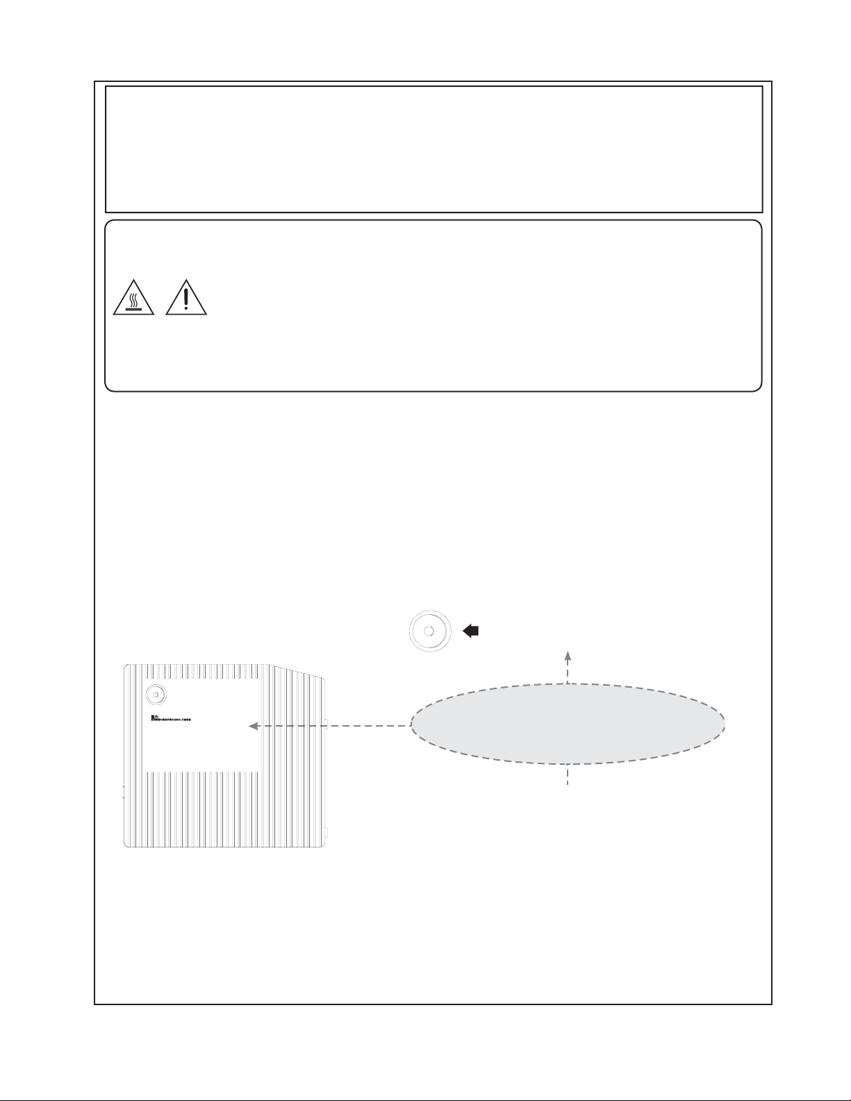
Potential hazard of glass particles if lamp ruptures.
In case of lamp rupture, contact your nearest
Authorized Projector Dealer or Service Center for a
replacement. See "Replacing the Lamp" on Page 31
Replacement Lamp Part Numbers:
UHP (120W Lamp) RP51
USER SERVICE SCREW.
VIS POUR ENTRETIEN PAR
L'UTILISATEUR.
Caution Concerning Lamp Replacement
See "Replacing the Lamp" on Page 31,32
iii
Page 4
WARING:FCC Regulations state that any unauthorized changes or modifications to this equipment not expressly
approved by the manufacturer could void the users authority to operate this equipment.
CAUTION:
This product satisfies FCC regulations when shielded cables and connectors are used to connect the unit to other
equipment. To prevent electromagnetic interference with electric appliances such as radios and televisions, use
shielded cables and connectors for connections.
DECLARATION OF CONFORMITY
REAR PROJECTION TV, MODEL RP51
This device complies with Part 15 of the FCC Rules. Operation is subject to the following two conditions:
(1) This device may not cause harmful interference, and (2) this device must accept any interference received,
including interference that may cause undesired operation.
RESPONSIBLE PARTY:
Vivitek Corp.
48017 Fremont Blvd.
Fremont, CA 94538
Service phone number : 1-877-603-3582
For Business Customers : URL http://www.vivitekcorp.com
INFORMATION:
This equipment has been tested and found to comply with the limits for a Class B digital device, pursuant to Part 15 of
the FCC Rules. These limits are designed to provide reasonable protection against harmful interference in a residential
installation. This equipment generates, uses and can radiate radio frequency energy and, if not installed and used
in accordance with the instructions, may cause harmful interference to radio communications. However, there is no
guarantee that interference will not occur in a particular installation. If this equipment does cause harmful interference
to radio or television reception, which can be determined by turning the equipment off and on, the user is encouraged
to try to correct the interference by one or more of the following measures:
-Reorient or relocate the receiving antenna.
-Increase the separation between the equipment and receiver.
-Connect the equipment into an outlet on a circuit different from that to which the receiver is connected.
-Consult the dealer or an experienced radio/TV technician for help.
"Note to CATV system installer: This reminder is provided to call the CATV system installers attention to Article 820-40
of the National Electrical Code that provides guidelines for proper grounding and, in particular, specifies that the cable
ground shall be connected to the grounding system of the building, as close to the point of cable entry as practical."
This product utilizes tin-lead solder, and fluorescent lamp containing a small amount of mercury. Disposal of these
materials may be regulated due to environmental considerations. For disposal or recycling information, please contact
your local authorities or the Electronic Industries Alliance : www.eia.org
TRADEMARKS
Manufactured under license from Dolby Laboratories. Dolby and the double-D symbol are trademarks of Dolby""
Laboratories.
Manufactured under license from BBE Sound, Inc.
Licensed by BBE Sound, Inc. under USP, 5510752 and 5736897. BBE and BBE sysbol are registered trademarks
of BBE Sound, Inc.
HDMI, the HDMI logo and High-Definition Multimedia Interface are trademarks or registered trademarks of HDMI
Licensing LLC.
R
DCDi by Faroudja is a registered trademark of Genesis Microchip Inc.
TM TM
DLP (Digital Light Processing) and DMD (Digital Micromirror Device) are trademarks of Texas Instruments, Inc.
Some IC chip in this product includes confidential and/or trade secret property belonging to Texas Instruments.
Therefore you may not copy, translate, distribute, reverse engineer, reverse assemble or discompile the contents
thereof
iv
Page 5
IMPORTANT SAFETY INSTRUCTIONS
CAUTION : Please read all of these instructions before you operate this product and save these instruction for later use.
Electricity is used to perform many useful functions, but it can also cause personal injuries and property damage if
improperly handled. This product has been engineered and manufactured with the highest priority on safety. However,
improper use can result in electric shock and/or fire. In order to prevent potential danger, please observe the following
instructions when installing, operating and cleaning the product. To ensure your safety and prolong the service life of
your Rear Projection Television, please read the following precautions carefully before using the product.
1) Read these instructions.
2) Keep these instructions.
3) Heed all warnings.
4) Follw all instructions.
5) Do not use this apparatus near water
6) Clean only with dry cloth.
7) Do not block any ventilation openings. Install in accordance with the manufacture's instructions.
8) Do not install near any heat sources such as radiators, heat registers, stoves, or other apparatus (including
amplifiers) that produce heat.
9) Do not defeat the safety purpose of the polarized or grounding-type plug. A polarized plug has two blades
with one wider than the other. A grounding type plug has two blades and a third grounding prong. The wide
blade or the third prong are provided for your safety. If the provided plug does not fit into your outlet, consult
an electrician for replacement of the obsolete outlet.
10) Protect the power cord from being walked on or pinched particularly at plugs, convenience receptacles, and
the point where they exit from the apparatus.
11) Only use attachments/accessories specified by the manufacturer
12) Use only with the cart, stand, tripod, bracket, or table specified by the manufacturer, or sold with the apparatus.
When a cart is used, use caution when moving the cart/apparatus combination to avoid injury from
tip-over.
13) Unplug this apparatus during lightning storms or when unused for long periods of time.
14) Refer all servicing to qualified service personnel. Servicing is required when the apparatus has been
damaged in any way, such as power-supply cord or plug is damaged, liquid has been spilled or
objects have fallen into the apparatus, the apparatus has been exposed to rain or moisture, does not
operate normally, or has been dropped.
15) Power Sources - This product should be operated only from the type of power source indicated on the
marking label. If you are not sure of the type of power supply to your home, consult your product dealer or
local power company. For products intended to operate from battery power, or other sources, refer to the
operating instructions.
16) Overloading Do not overload wall outlets, extension cords, or integral convenience receptacles as this can
result in a risk of fire or electric shock.
17) Object and Liquid Entry Never push objects of any kind into this product through openings as they may
touch dangerous voltage points or short-out parts that could result in a fire or electric shock. Never spill liquid
of any kind on the product.
18) Damage Requiring Service Unplug this product from the wall outlet and refer servicing to qualified service
personnel under the following conditions:
a) When the AC cord or plug is damaged,
b) If liquid has been spilled, or objects have fallen into the product,
c) If the product has been exposed to rain or water
d) If the product does not operate normally by following the operating instructions.
Adjust only those controls that are covered by the operating instructions as an improper
adjustment of other controls may result in damage and will often require extensive work by a
qualified technician to restore the product to its normal operation,
e) If the product has been dropped or damaged in any way, and
f) When the product exhibits a distinct change in performance this indicates a need for service.
19) Replacement Parts - When replacement parts are required, be sure the service technician has used
replacement parts specified by the manufacturer or have the same characteristics as the original part.
Unauthorized substitutions may result in fire, electric shock, or other hazards.
20) Safety Check Upon completion of any service or repairs to this product, ask the service technician to
perform safety checks to determine that the product is in proper operating condition.
v
Page 6
IMPORTANT SAFETY INSTRUCTIONS
Water and Moisture - Do not use this product near water-for example, near a bath tub, wash bowl, kitchen sink, or
laundry tub; in a wet basement; or near a swimming pool; and the like.
Selecting the location - Select a place with no direct sunlight and good ventilation.
Ventilation - The vents and other openings in the cabinet are designed for ventilation. Do not cover or block these
vents and openings since insufficient ventilation can cause overheating and/or shorten the life of the product. Do not
place the product on a bed, sofa, rug or other similar surface, since they can block ventilation openings. This product
is not designed for built-in installation; do not place the product in an enclosed place such as a bookcase or rack,
unless proper ventilation is provided or the manufacturer's instructions are followed.
Heat - The product should be situated away from heat sources such as radiators, heat registers, stoves, or other
products (including amplifiers) that produce heat.
Lightning - For added protection for this television equipment during a lightning storm, or when it is left unattended
and unused for long periods of time, unplug it from the wall outlet and disconnect the antenna. This will prevent
damage to the equipment due to lightning and power-line surges.
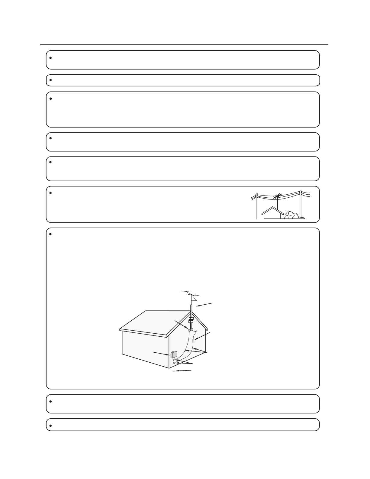
Power Line - An outside antenna system should not be located in the vicinity of
overhead power lines or other electric light or power circuits, or where it can fall into
such power lines or circuits. When installing an outside antenna system, extreme care
should be taken to keep from touching such power lines or circuits as contact with
them might be fatal.
Outdoor Antenna Grounding - If an outside antenna is connected to the television equipment, be sure the antenna
system is grounded so as to provide some protection against voltage surges and built-up static charges.
Article 810 of the National Electrical Code, ANSI/NFPA 70, provides information with regard to proper grounding of
the mast and supporting structure, grounding of the lead-in wire to an antenna discharge unit, size of grounding
conductors, location of antenna-discharge unit, connection to grounding electrodes, and requirements for the
grounding electrode.
EXAMPLE OF ANTENNA GROUNDING AS PER
NATIONAL ELECTRICAL CODE, ANSI/NFPA 70
ANTENNA
LEAD IN
WIRE
GROUND
CLAMP
ANTENNA
ELECTRIC
SERVICE
EQUIPMENT
NEC - NATIONAL ELECTRICAL CODE
POWER SERVICE GROUNDING
ELECTRODE SYSTEM
(NEC ART 250, PART H)
DISCHARGE UNIT
(NEC SECTION 810-20)
GROUNDING CONDUCTORS
(NEC SECTION 810-21)
GROUND CLAMPS
To prevent fire or shock hazard, do not expose this product to dripping or splashing. No objects filled with liquids,
such as vases, should be placed on the product.
To prevent fire or shock hazard, do not place the AC power cord under the TV set or other heavy items.
vi
Page 7

Contents
DEAR CUSTOMER ii
IMPORTANT INFORMATION ii
TRADEMARKS iv
IMPORTANT SAFETY INSTRUCTIONS v
Contents 1
Main Features 2
Supplied Accessories 3
Before Operating Your Rear Projection Television 3
Cleaning & Maintenance
Antenna Connections 6
Television Antenna Connection Protection
Using The Video and Audio Input Terminals 8
Connecting your Digital Video Equipment (HDMI & DVI)
Connecting your DVD Player 10
Connecting your GAME CONSOLE or CAMCORDER
Connecting Your Computer 13
Computer Compatibility Chart 14
Using the Center Channel Input 15
Using the Audio Output 16
Side Control Section 17
Status LED 18
Remote Control Key Functions 19
Remote Control Operation 22
Menu Functions 24
Getting Started 24
Using the On Screen Display (OSD) 25
Setting a Password for Parental Control 29
Using Wide Modes: View Mode 30
Replacing the Lamp 31
Status LEDs 32
Troubleshooting Guide 33
Specifications 35
Dimension 36
Input / Output Terminals and Connectable Equipment
APPENDIX: Remote Control IR Set Up Codes
Index
5
6
9
12
37
38~49
50~51
1
Page 8

Main Features
Please enjoy your Rear Projection Television (RPTV) that features:
Texas Instruments latest DLP (Digital Light Processing) third generation HD4 Digital Micromirror Device
R
(DMD) which features Smooth Picture technology for the very best image quality.
Built in ATSC and NTSC tuners for enjoying digital and analog "off air" broadcast signals.
View high definition signals by using an external HDTV Set Top Box (Satellite or Cable) and RGB, HDMI, DVI or
component video outputs from the STB into the RPTV.
An HDMI terminal for Digital video equipment that supports HDCP (Hight-bandwidth Digital Content Protection).
Two high-definition capable component video inputs that automatically synchronize with your RPTV to match the
incoming source.
Three sets of A/V inputs for conventional video equipment such as DVD players, VCRs etc.
PC signal input: RGB D-SUB
Supported signals:
480i, 480p, 720p and 1080i
Automatically converts all signals to 720p display format.
HDMI Video Mode: 480p, 720p, 1080i.
HDMI PC Mode: VGA
Computer Input : 1024x768 XGA
Bright, Flicker-free image with outstanding image detail and clarity.
Film Mode 3:2 pull down for automatic detection and conversion of film based content for accurate display with
minimal motion artifacts and video noise.
High contrast ratio that delivers accurate color processing and deep black levels.
Picture-in-Picture (PIP) modes that let you watch multiple programs or video sources simultaneously
A Digital Zoom mode that eliminates back bars around the display image.""
An integrated audio system featuring BBE sound processing for maximized sound quality.
Center Channel Input terminal that is convenient for Home Theater set up.
Light up Universal Remote control
TM
TM
TM
Other benefits include:
No possible convergence errors.
No screen aging, image retention or burn in effects.
User-friendly replaceable lamp for hours of enjoyment.
2
Page 9
Supplied Accessories
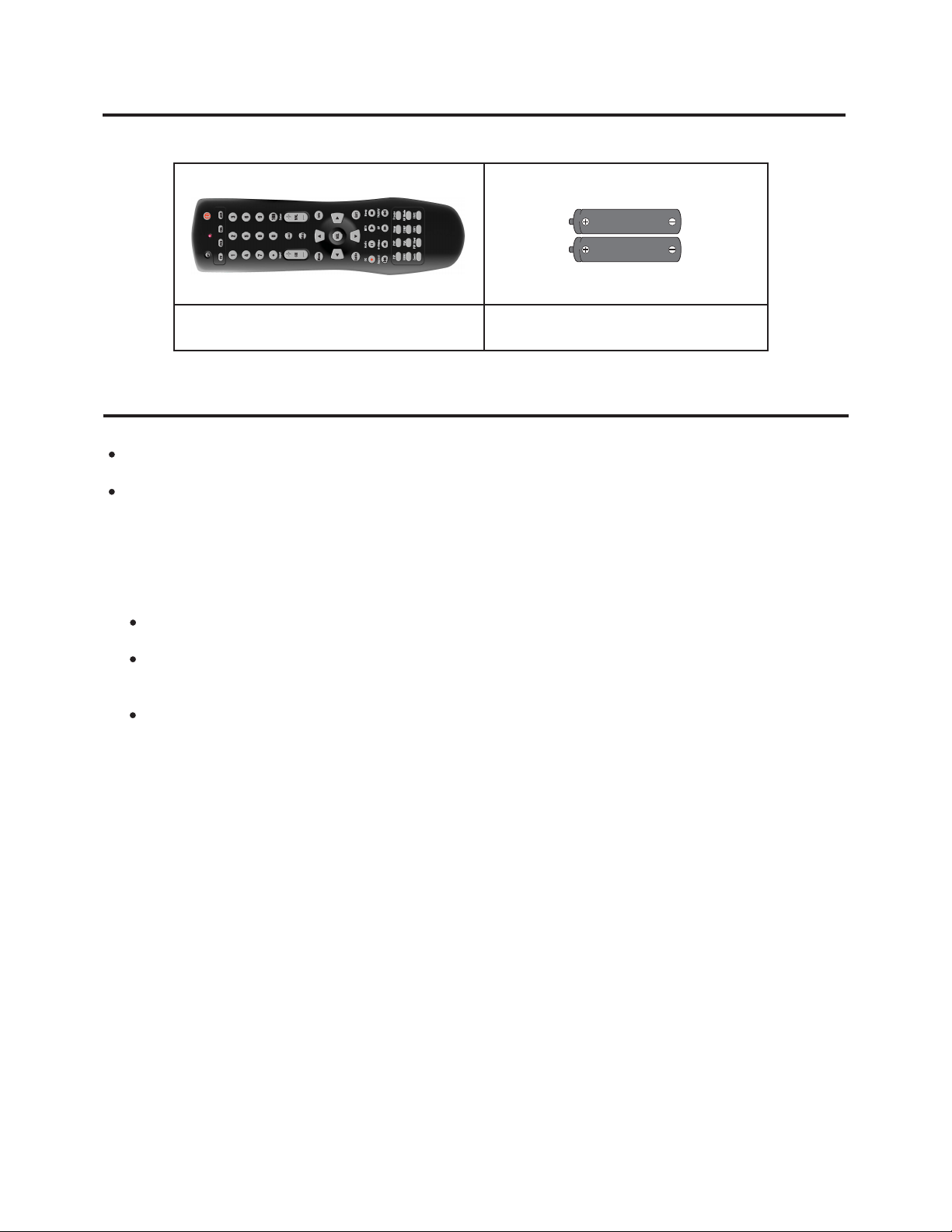
Multi-function Remote Control
Size AA
Dry Batteries (2pcs.)
Before Operating Your Rear Projection Television
Location
For normal operation, your RPTV should be set up in the room where cool, adequate ventilation is provided. Do
not position the back of the RPTV in a place where free airflow is restricted.
Any magnetic force may disturb the color picture. Make sure that magnets, speakers, electric clocks, toys using
magnets or any other magnetic equipment, such as an iron are kept well away from this RPTV.
Power
Your RPTV operates on AC 120 Volts, 60 Hertz (normal household current in the USA) and has a polarized plug. If
you are unable to insert the plug fully into the outlet, try reversing the plug. If it does not fit, contact an electrician. Do
not defeat the safety feature of the polarized plug.
If the RPTV is not used for a long period, unplug the RPTV from the wall outlet to economize power.
(If the RPTV is plugged in, slight current still flows, even with the POWER button in the OFF position.)
When a FM tuner or radio is located near the RPTV Lines and other noise may appear in TV broadcast
images when radio and TV broadcasts are received at the same time. If video noise more appears, turn off either
the RPTV or the radio.
If you are listening to AM broadcasts, turn the RPTV off. Some AM broadcast signals may not be received due to
interference from the RPTV.
3
Page 10
Viewing
Your TV is best viewed by sitting directly in front of it about 10 to 18 feet from the screen. The brightness decreases
as the viewer moves to the left or to the right of the set.
During the daytime, reflections from light outside may appear on the screen. Drapes or screens can be used to
reduce the reflection or the RPTV can be placed in a different location of the room.
If the RPTV's audio output is connected to a Hi-Fi system's external speakers, the best audio performance will
be obtained by placing the speakers on each side of the set at an equal distance as well as on a height which is
equal to that of the screen center. For best stereo separation, first place the external speakers at least four feet
from each side of the RPTV, then place the surround speakers to the side or behind the viewing area. Due to the
differences in room sizes and acoustic environments some experimentation regarding speaker placement for best
performance will be required.
Remote Control
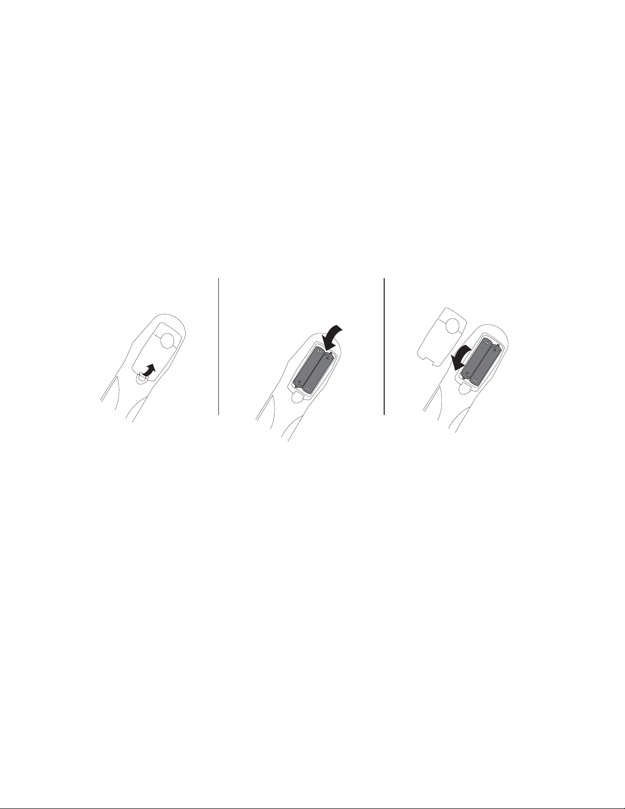
To use the remote control, insert batteries first.
1. Open the battery cover.
Pull up the lid in the
direction of the arrow.
2. Load the batteries. Insert
two "AA" size batteries
supplied so that the battery
poles are positioned as
Indicated.
3. Close the battery cover
Lower the lid in the direction of the arrow.
4
Page 11

Cleaning & Maintenance
Cleaning the Screen
The screen of the RPTV has been specially treated. To clean users should wipe the surface gently using only a
cleaning or a soft, lint-free cloth. If the surface is particularly dirty, use a little water on the cloth (never directly on
the screen), then wipe the screen with it.
Reminders:
Do not use substances such as glass cleaners, solvents and/or thinners.
Do not scratch or hit the surface of the screen with fingers or any hard objects.
The screen of the RPTV is made of specially coated plastic and can be scratched or damaged by abrasive or
ammonia-based window cleaners. Scratches on the bezel or screen are not covered by the warranty.
Cleaning the Exterior
The RPTV is cooled by air circulated through the vents in the case so for optimized performance, keep the vents
clear of dust. To clean, turn off and unplug the RPTV, then brush the dust away from the vents with a damp cloth.
Be careful not to drip any water into the vents.
Reminders:
Do not attempt to clean dust from the inside of the RPTV.
Do not use abrasives or solvent cleaners because they can damage the finish on the components.
Do not allow any excessive water or moisture to come into contact with the surface of the DLP TV. If water or
moisture gets inside the RPTV, operating problems and electrical hazards may result.
Do not scratch or hit the surface of the screen with fingers or any hard objects.
Do not place articles made of rubber or PVC near the cabinet for any extended periods of time.
5
Page 12
Antenna Connections
TTo fully utilize the various features provided, such as the 2- Tuners Picture In Picture System, UNIVERSAL PLUS,
and some connectors for high-quality VCR/DVD playback, set up this unit properly by following the procedures
below.
Remote Control
The Remote Control is compatible with various VCR/DVD players and other manufacture's AV equipment by
setting the correct control code. (Page 38~49)
Antennas
The antenna required for good color RPTV reception are more important than those for black & white television
reception. For this reason, a good quality outdoor antenna is strongly recommended.
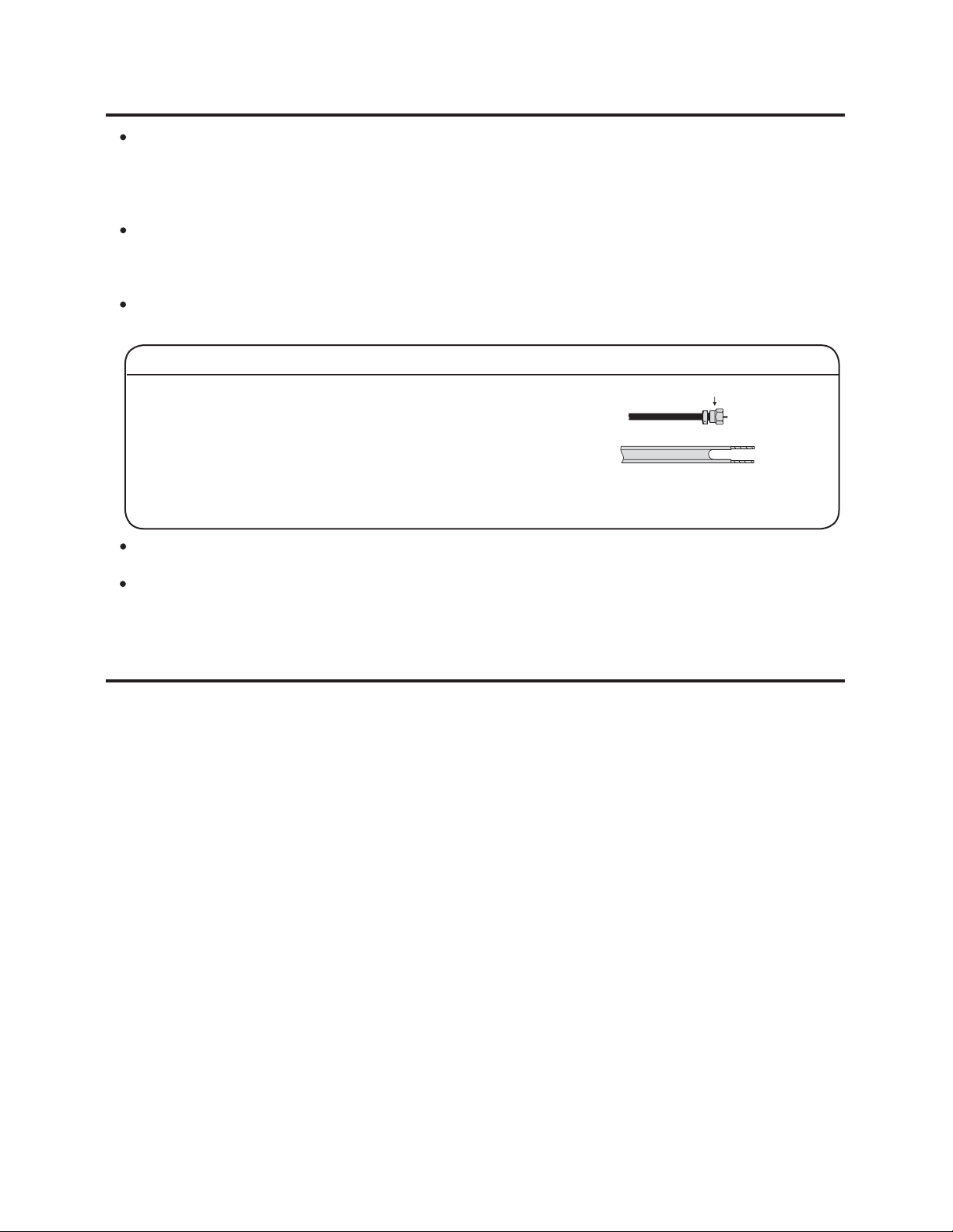
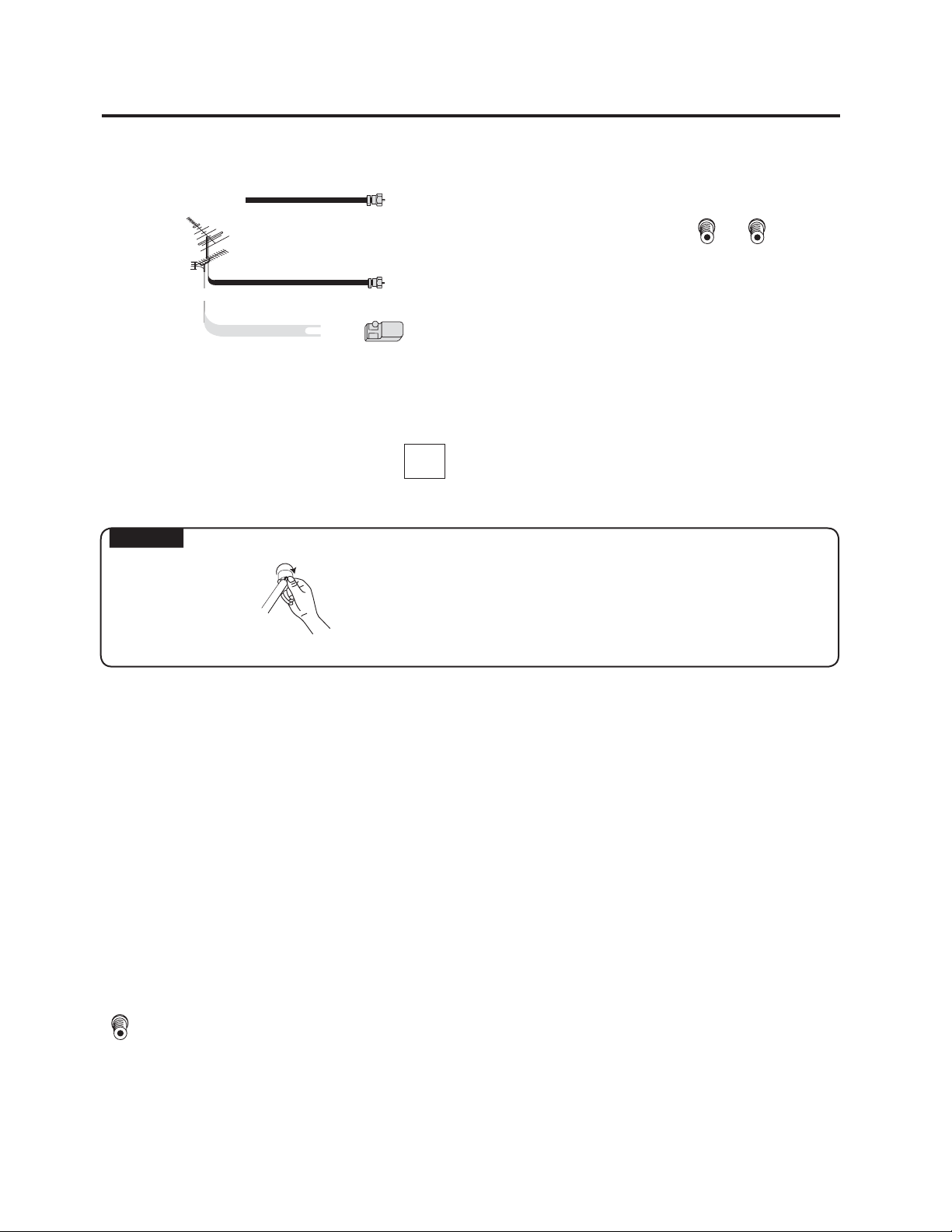
Type of connector
1. The 75 ohm system generally uses a round cable with an F-type
connector that can easily be attached to a terminal without tools
(not supplied) The F-type connector should be finger tightened
only.
2. The 300 ohm system uses a flat "twin-lead" cable that can be
attached to a 75 ohm terminal through a 300-75 ohm ADAPTOR
(not supplied)
A good color picture depends on a strong TV signal. Ask your dealer for advice on how to install your external
antenna to receive the best possible signal.
If you subscribe to Cable or Satellite TV or have a central antenna in your building, you may not need an external
Antenna.
75-ohm coaxial cable (round)
300-ohm twin-lead cable (flat)
F-type connector
Television Antenna Connection Protection
External Television Antenna Grounding
If an outside antenna or cable system is to be connected to the RPTV, make sure that the antenna or cable system
is electrically grounded to provide some protection against voltage surges and static charges. Please refer to the
operating or operation manual of your antenna or cable system for further information.
Article 810 of the National Electrical Code, ANSI/NFPSA 70, provides information with regard to proper grounding
of the mast and supporting structure, grounding of the lead-in wire to an antenna discharge unit, size of grounding
conductors, location of antenna discharge unit, connection to grounding electrodes, and requirements for the
grounding electrode.
Lightning Protection
For added protection of the RPTV during a lightning storm or when it is left unattended or unused for long periods
of time, unplug the RPTV from the wall outlet and disconnect the antenna or cable system.
Power Lines
Do not locate the antenna near overhead light or power circuits, or where it could fall into such power lines or
circuits.
6
Page 13
Antenna Connections
Cable TV lead-in
VHF, UHF or
VHF/UHF combination
antenna
75 ohm coaxial cable (round)
or
NOTICE:
F-type connector
75-ohm coaxial cable
300-75 ohm ADAPTOR
(Not supplied)
F-type connector shold be finger-tightenned only.
When connecting the RF cable to the TV set, do not
tighten F-type connector with tools.
If tools are used, it may cause damage to your TV set.
(The breaking of internal circuit, etc.)
CABLE TV (CATV) CONNECTION
A 75 ohm coaxial cable connector is built into the set for easy hookup. When connecting the 75 ohm coaxial
cable to the set, screw the 75 ohm cable to the COAXIAL CABLE CONNECTOR.
Some cable TV companies offer "premium pay channels". Since the signals of these premium pay channels are
scrambled, a cable TV converter/descrambler is generally provided to the subscriber by the cable TV company.
This converter/descrambler is necessary for normal viewing of the scrambled channels. (Set your TV on channel
3 or 4. Typically one of these channels is used. If channel is unknown, consult your cable TV company.) For more
specific instructions on installing cable TV, consult your cable TV company. One possible method of utilizing the
converter/descrambler provided by your cable TV company is explained below.
Please note: RF switch equipped with position A/B (not provided) is required.
A"A" position on the RF switch (not supplied) : You can view all unscrambled channels using the TV's channel keys.
"B" position on the RF switch (not supplied) : You can view the scrambled channels via the converter/descrambler
using the converter's channel keys.
7
Page 14
Using The Video and Audio Input Terminals
Using the Video and Audio Input Terminals
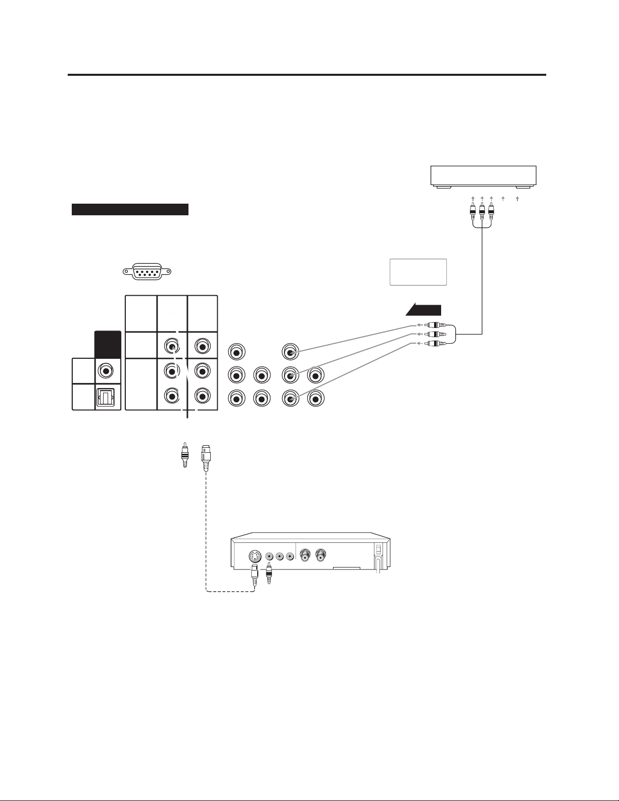
Connecting video equipment for video playback.
When the television is connected to video equipment as shown below , the material being played back on the video
equipment can be seen on the television screen.
Back of Rear Projection TV
Audio Cable (Not supplied)
S-Video Cable (Not supplied)
DVD,VCR OR VIDEO Equipment
VIDEO
S-VIDEO
AUDIO
LR
IN
OUT
8
Page 15
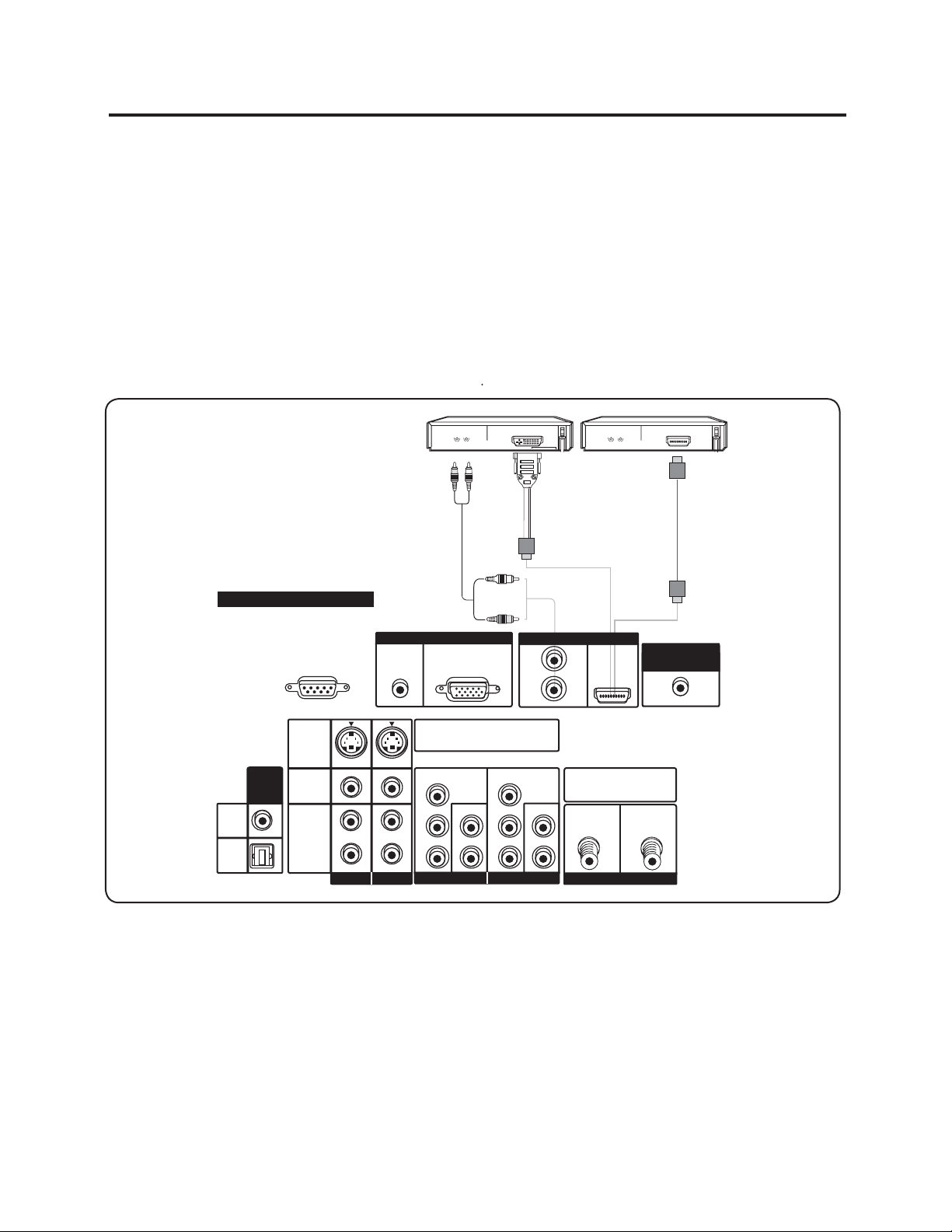
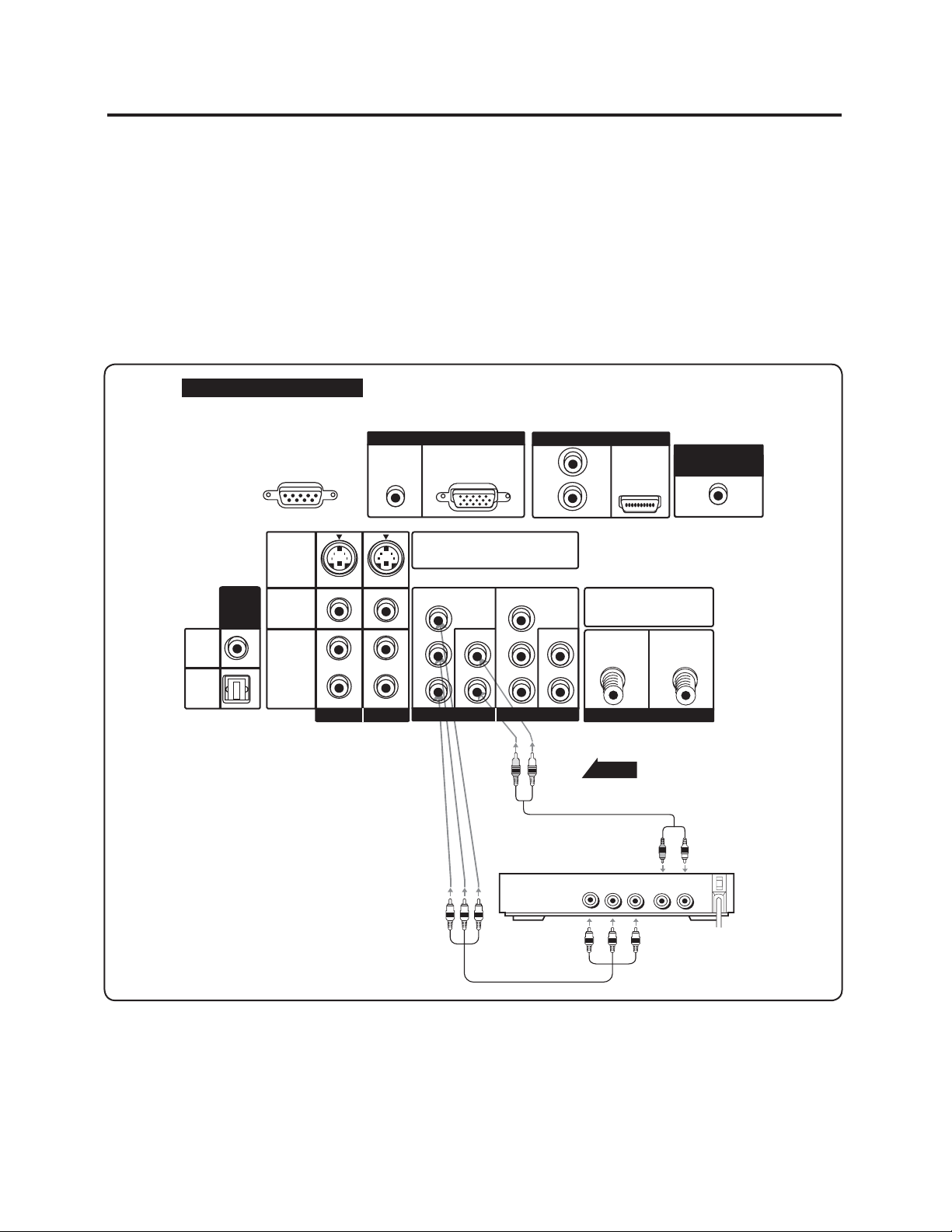
Connecting your Digital Video Equipment (HDMI & DVI )
Using Digital Video
Digital video equipment and other devices that have a digital interface compliant with the HDMI & DVI (Digital
Visual Interface) standard should be connected to the HDMI input of the RPTV.
Note:
1. Turn off the power of the RPTV and digital video equipment.
2. Connect a HDMI cable to the output terminal of your digital video equipment and the other end to the HDMI input
in the rear of your RPTV.
3. Turn on the power to the RPTV and your digital video equipment.
4. Select HDMI using the INPUT button on the right side of the RPTV or the remote control.
5. If your digital video equipment provides DVI output only, you should connect the DVI output from your Digital
video equipment to the HDMI input on the rear of your RPTV Connect both audio cables.
6. When using the DVI cable to reset OSD menu for "HDMI AUDIO" see page 27.
7. If your digital video equipment provides HDMI output, you should connect the cable from your digital video
equipment to the HDMI input on the rear of your RPTV
DIGITAL VIDEO Equipment
Back of Rear Projection TV
FOR SERVICEONLY
(RS-232C)
S-VIDEO
DIGITAL
AUDIO
VIDEO
L
AUDIO
R
COAXIAL
OPTICAL
OUTPUT
(ATSConly)
(ATSConly)
AV IN 1AV IN1
PC INPUTPC INPUT
AUDIO(L/R)
Enter theS-VIDEO or theVIDEO terminal
can beused, but theS-VIDEO overrides
the VIDEOterminal.
Y
L
P
B
R
PR
COMPONENT IN1
AV IN 2AV IN2
AUDIO Cable (Not supplied)
RGB
L
AUDIO
R
DVI
HDMI
L
AUDIO
R
Y
PB
L
AUDIO
PR
R
COMPONENT IN2
DVI TO HDMI Cable (Not supplied)
HDMI
Make sureANALOG/DIGITAL RF
Inputs areconnected correctly.
ANALOG
ANTENNA IN
HDMI
HDMI Cable (Not supplied)
CENTER CHANNELCENTER CHANNEL
INPUT
DIGITAL
Note:
a). The High Definition Multimedia Interface (HDMI). This interface is used between any audio/video source, such
as a set-top box, DVD player, or A/V receiver, and an audio or video monitor, such as a DTV. HDMI supports
standards, enhanced or high-definition video, plus-multi-channel digital audio on a single cable. The format
transmits all ATSC HDTV standards and supports eight-channel digital audio (up to 192kHz sampling rate),
with bandwidth to spare for future enhancements.
HDMI also uses a more compact and consumer electronics-friendly 15mm, 19-pin connector and will be fully
compatible with the former DVI-HDCP standard.
The HDMI input on your RPTV supports High-bandwidth Digital Content Protection (HDCP). HDMI encrypts the
transmission between the video source and the digital display for added security and protection.
b). Refer to your Digital Device's User Manual for more information about the video output requirements of the
product.
9
Page 16
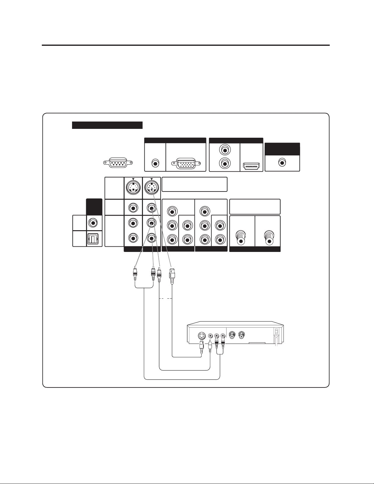
Connecting your DVD Player
Using S-Video or Composite video
1. Turn off the power of the RPTV and DVD player.
2. Connect the S-Video or video (yellow color) terminal from the rear of your DVD player to the S-Video or video
(yellow color) terminal in the AV IN on the rear of your RPTV.
3. Connect the R (red color) and L (white color) audio connectors from the rear of your DVD player to the R (red
color) and L (white color) audio input connectors in the AV IN 2 on the rear of your RPTV.
4. Turn on the power of the RPTV and DVD player.
5. Select AV 2 using the INPUT button on the right side of the RPTV or on the remote control.
Back of Rear Projection TV
COAXIAL
OPTICAL
FOR SERVICE ONLY
DIGITAL
AUDIO
OUTPUT
(ATSConly)
(ATSConly)
(RS-232C)
S-VIDEO
VIDEO
AUDIO
L
R
AV IN1AV IN1
AUDIO(L/R)
L
R
AV IN2AV IN2
PC INPUTPC INPUT
RGB
Enter theS-VIDEO or theVIDEO terminal
can beused, but theS-VIDEO overrides
the VIDEOterminal.
Y
P
B
L
PB
AUDIO
PR
COMPONENT IN1
or
PR
R
L
AUDIO
R
Y
L
AUDIO
R
COMPONENT IN2
VIDEO Equipment
HDMI
CENTER CHANNELCENTER CHANNEL
Make sureANALOG/DIGITAL RF
Inputs areconnected correctly.
ANALOG
DIGITAL
ANTENNA IN
INPUT
Video Cable (Not supplied)
S-Video Cable (Not supplied)
AUDIO Cable (Not supplied)
Note:
a). If you are already using the AV IN 2input for another component, or you do not want to use the AV IN 2 input for
the DVD player, you can connect the DVD player to the AV IN 1 group of connections.
b). Refer to your DVD player User Manual for more information about the video output requirements of the product.
10
Page 17
Connecting your DVD Player
Using Component Videoo
1. Turn off the power to the RPTV and DVD player.
2. Connect the PR or CR (red color) connector from the rear of your DVD player to the PR/CR (red color)
connector in the COMPONENT IN 1 on the rear of your RPTV.
3. Connect the PB or CB (blue color) connector from the rear of your DVD player to the PB/CB (blue color)
connector in the COMPONENT IN 1 on the rear of your RPTV.
4. Connect the Y (green color) connector from the rear of your DVD player to the Y (green color) connector in the
COMPONENT IN 1 on the rear of your RPTV.
5. Connect the R (red color) and L (white color) audio connectors from the rear of your DVD player to the R (red
color) and L (white color) audio input connectors in the COMPONENT IN 1 from the rear of your RPTV.
6. Turn on the power of the RPTV and DVD player.
7. Select COMP 1 using the INPUT button on the right side of the RPTV or on the remote control.
Back of Rear Projection TV
COAXIAL
OPTICAL
FOR SERVICE ONLY
DIGITAL
AUDIO
OUTPUT
(ATSConly)
(ATSConly)
(RS-232C)
S-VIDEO
VIDEO
AUDIO
L
R
AV IN1AV IN1
AUDIO(L/R)
L
R
AV IN2AV IN2
PC INPUTPC INPUT
RGB
Enter theS-VIDEO or theVIDEO terminal
can beused, but theS-VIDEO overrides
the VIDEOterminal.
Y
B
P
L
PB
AUDIO
PR
COMPONENT IN1
PR
R
L
AUDIO
R
Y
L
AUDIO
R
COMPONENT IN2
VIDEO Equipment
HDMI
Make sureANALOG/DIGITAL RF
Inputs areconnected correctly.
ANALOG
DIGITAL
ANTENNA IN
Signal
Audio cable
(not supplied)
YPBP
AUDIO
R
CENTER CHANNELCENTER CHANNEL
INPUT
LR
Component cable
(not supplied)
Note:
a). If you are already using the Component IN1 input for another component, or you do not want to use the
Component IN1 input for the DVD Player, your can connect the DVD player to the Component IN2 group of
connection.
b). Refer to your DVD player User Manual for more information about the video output requirements of the product.
11
Page 18
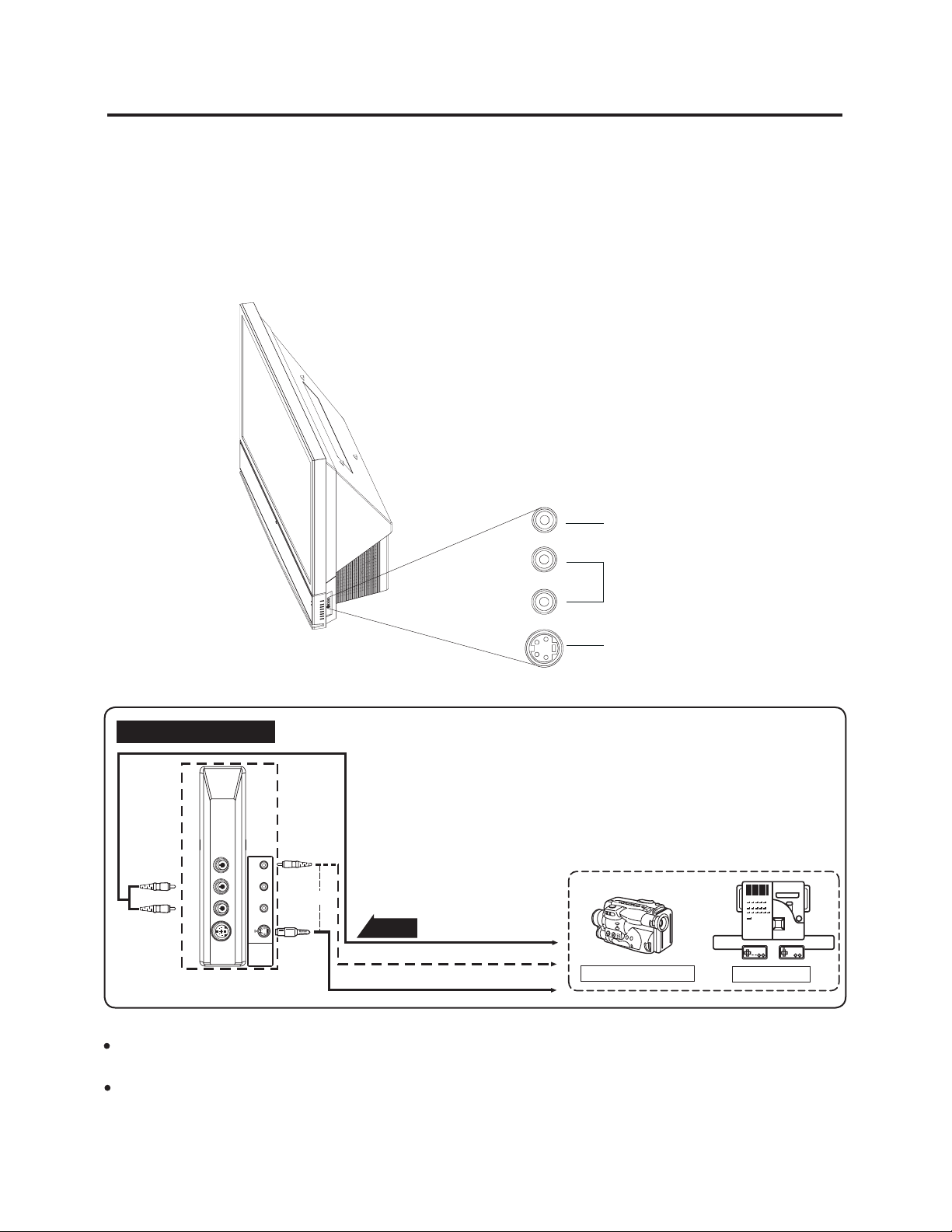
Connecting your GAME CONSOLE or CAMCORDER
Using S-Video
1. Turn off the power of the RPTV and GAME CONSOLE or CAMCORDER.
2. Connect the S-Video terminal from your GAME CONSOLE or CAMCORDER to the S-Video terminal in AV IN 3 on
the right side of your RPTV.
3. Connect the R (red color) and L (white color) audio connectors from your GAME CONSOLE or CAMCORDER to
the R (red color) and L (white color) audio input connectors in AV IN 3 on the right side of your RPTV.
4. Turn on the power to the RPTV and GAME CONSOLE or CAMCORDER.
5. Select AV IN 3 using the INPUT button on the right side of the RPTV or on the remote control.
VIDEO
SIDE terminals of RPTV
VIDEOR-AUDIO-L
S-VIDEO
L
R
S-VIDEO
VIDEO EQUIPMENT (OUTPUT)
or
Signal
AV IN3
To AUDIO OUTPUT
To VIDEO OUTPUT
To S-VIDEO OUTPUT
CAMCORDER
TV GAME
Note:
The S-VIDEO INPUT terminal offers a higher quilty image by accepting the signal separated into color and brightness
signals.
The S-VIDEO INPUT terminal are for video signal only. The audio signals are connected to AV IN3.
12
Page 19

Connecting Your Computer
Using PC INPUT
1. Turn off the power of the RPTV and Computer.
2. Connect a VGA cable from the VGA CARD of your computer to the PC input in the rear of your RPTV.
3. Connect the Audio Out mini-jack from your computer to the VGAAudio ( L/R ) from the rear of your RPTV.
4. Turn on the power of the RPTV and your computer.
5. Select RGB using the INPUT button on the right side of the RPTV or on the remote control.
Back of Rear Projection TV
RGB TERMINAL
Connecting the
computer to display
the PC MODE
(See page 25)
Do not connect any cable
For service only connector is for
production testting and service
only. Could not connect any
irrelevant computer cable that will
be dameage your RPTV.
FOR SERVICE ONLY
(RS-232C)
AUDIO(L/R)
(Not supplied)
VGA Cable and Mini-Jack
PC INPUTPC INPUT
RGB
L
AUDIO
R
HDMI
CENTER CHANNELCENTER CHANNEL
INPUT
Enter theS-VIDEO or theVIDEO terminal
can beused, but theS-VIDEO overrides
the VIDEOterminal.
Y
P
B
L
AUDIO
PR
R
COMPONENT IN1
Y
PB
L
AUDIO
PR
R
COMPONENT IN2
Make sureANALOG/DIGITAL RF
Inputs areconnected correctly.
ANALOG
DIGITAL
ANTENNA IN
COAXIAL
OPTICAL
DIGITAL
AUDIO
OUTPUT
(ATSConly)
(ATSConly)
S-VIDEO
VIDEO
AUDIO
L
R
AV IN1AV IN1
L
R
AV IN2AV IN2
Note:
a). The PC input on your RPTV supports High-bandwidth Digital Content Protection (HDCP). HDCP encrypts the
transmission between the video source and the digital display for added security and protection.
b). Refer to your computer User Manual for more information about the video output requirements of the product.
13
Page 20

Computer Compatibility Chart
Computer
Multiple signal support
Horizontal Frequency: 15-60 kHz,
Vertical Frequency: 45-85 Hz,
Pixel Clock: 12-80 MHz
Compatible with sync on green signal
XGA compatible in intelligent compression
Intelligent Compression and Expansion System re
sizing technology
Sync signal: Compatible with TTL level
Input
mode Signal Format STRETCH NORMAL ZOOM DOT BY DOT Factory Preset
RGB
HDMI
640*400
720*400
720*480 60Hz O O O O NORMAL
640*480
800*600
1024*768
1280*720 60Hz X X X O -
640*480 60Hz O O O O SIDE BAR
No Signal O X X X -
70Hz O O O O NORMAL
85Hz O O O O
70Hz O O O O NORMAL
85Hz O O O O
60Hz O O O O NORMAL
72Hz O O O O
75Hz O O O O
85Hz O O O O
56Hz O O O O NORMAL
60Hz O O O O
70Hz O O O O
72Hz O O O O
75Hz O O O O
85Hz O O O O
60Hz O O O O NORMAL
70Hz O O O O
75Hz O O O O
O : Possible
X : Not Possible
Note :
This RPTV may not be able to display images from notebook computers in simultaneous (CRT/LCD) mode. Should
this occur, turn off the LCD display on the notebook computer and output the display data in "CRT only" mode.
Details on how to change display modes can be found in your notebook computer's operation manual.
When signal not supported inputs, the screen will show "UNAVAILABLE" words ; But when the signal supported
inputs and shows picture oblique, need to used "AUTOSYNC" function, if "AUTOSYNC" function picture still have
oblique , must choose "H-POS/V-POS" to adjust it.
When RGB source signal input and the timing is 640x400, 720x400, 640x480 and 720x480, you need to use the
"setup" menu and adjust the "input signal" to get the better picture dsiplay.
14
Page 21

Using the Center Channel Input
You can use the RPTV speakers as a center speaker when using 5.1ch surround sound system.
1. Turn off the power of the RPTV and audio equipment which supports 5.1ch surround sound system.
2. Connect the center speaker connector from the rear of your audio equipment to the CENTER CHANNEL INPUT
on the rear of your RPTV.
3. Turn on the power of the RPTV and audio equipment.
4. Press MENU button on the remote control and the "MAIN MENU" will be displayed on the screen.
5. Press the or button to select "SETUP".
6. Press the OK button and the main menu will change to the "SETUP".
7. Press the or button to select "SPEAKERS".
8. Press the OK button.
9. Press the or button to select "CENTER-IN".
Speaker System
CENTER CHANNEL
CENTER CHANNEL
INPUT
AV AMPLIFIER
DVD PLAYER, etc.
Note:
Refer to your audio equipment operation manual for details.
15
Page 22

Using the Audio Output
These terminals are used for connecting a stereo amplifier for Digital TV Audio Signals only. They relay (pass-
through) the audio signals of all DTV programs displayed on the RPTV screen.
16
Page 23

Side Control Section
POWER
Switch the TV on by pressing the""
POWER button once. To turn "off" the TV
press the POWER button twice; the first
time the button is pressed a message will
appear on the screen warning that the
second button press will power-off the TV.
INPUT
Repeated pressing of this button steps
through the input sources in a circulatory
sequence. Once you have selected all of
the inputs you will return to the input you
Started.
MENU
Pressing this button activates the On
Screen Display (OSD) and shows the
Main Menu. Pressing this button again
exits (closes) the OSD.
ENTER
Pressing this button activates the OSD
and shows the Main Menu.
CHANNEL /
Step up ( ) or down ( ) through TV
channels. While the OSD is active, these
function as adjustment buttons to select
OSD options.
VOLUME /
Increase ( ) or decrease ( ) the speaker
volume. While the OSD is active, these function as adjustment buttons to adjust the OSD options.
17
Page 24

Status LED
Front Panel Indicator
READY LED
Displays the status of the ready of your RPTV.
POWER LED
Lights green when powered on.
Remote Control Sensor
Point the Remote Control here as this is the window through which all of the remote signals pass to reach the
remote sensor.
REMOTE CONTROL
SENSOR
18
READY
POWER
READY LED
POWER LED
Page 25

Remote Control Key Functions
The Remote Control is a comprehensive remote that can be used to
control up to eight different components. For ease of use with minimal
room lighting the Remote Control has a back light that illuminates all of
the buttons when any button is pressed. The light will automatically go
off a few seconds after the last button is pressed. The Remote Control
button functions are explained below.
Remote LED
19
Page 26

Remote Control Key Functions
VIEW MODE (WITH VIDEO)
STRETCH 16:9
SIDE BAR 4:3
S.STRETCH
ZOOM
VIEW MODE (WITH PC)
NORMAL
STRETCH 16:9
DOT BY DOT
ZOOM
EXIT
Exit the OSD, component or menus.
Use these buttons to navigate the OSD menus.
SEL
Confirm an action on each menu item. and Select the main or
sub (PIP) window to activate.
INFO
Display the current status of the video source, audio (and channel
number when in TV mode), on the screen of your RPTV.
MENU
Activates the OSD Menu and Exit the OSD directly.
20
Page 27

Remote Control Key Functions
PIP
Turn on or off the PIP (Picture In Picture) or POP (Picture On Picture) mode.
PIP MODE
Select the style of the PIP mode.
AUDIO
Selects audio effect mode.
SWAP
Swap the main picture and sub picture when the PIP or POP mode is on.
Change the video source for the PIP or POP sub picture.
When chosen with one of the Component buttons, tells the VCR, CD or
DVD player to pause.
MTS
Selects stereo, sap and mono sound mode when input source is TV.
ZOOM
Switch the zoom size to magnify the display to 2X, 4X image.
CC
Turns closed captioning "on" and "off".
FREEZE
Freeze the picture. Note that the video and audio content will continue
to change and when the button is pressed again, turning off the Freeze
mode, the picture will not return to the same point as when it was frozen.
TV / DTV
Selects TV as the video source.
COMP
Alternately selects the component input COMP1 or COMP2.
HDMI
Selects HDMI as the video source.
VGA
Selects PC as the video source.
AV
Alternately selects the AV1, AV2 or AV3 inputs.
AV MODE
Preset AV Settings : STANDARD, MOVIE, GAME, USER-TV, DYNAMIC
(FIXED), DYNAMIC.
PIP VIEW
Switch view mode of sub window to 16:9 or 4:3
FAV1
Selects favorite cable/air channels for TV source.
FAV2
Selects favorite channels for DTV source.
21
Page 28

Remote Control Operation
CAUTIONS :
Do not drop or mishandle the remote control.
Do not get the remote control wet. If the remote control gets wet, wipe it dry immediately.
Avoid heat and humidity.
When not using the remote control for a long period, remove the batteries.
Do not take apart the batteries, heat them, or throw them into a fire.
Using the PIP Feature on the Remote Control
Press the PIP button on the Remote Control to activate the PIP (Picture-In-Picture) mode. The PIP (sub screen)
window will appear on the screen superimposed on the main screen. When you press this button again it will
deactivate the PIP mode and the window will disappear.
When the PIP window is visible, press the SWAP button and the main picture will switch to the PIP window and
the PIP picture will replace it on the main screen, Press the SWAP button again and the pictures will switch back
again.
When the PIP window is visible, press the PIP MODE button and the RPTV will show the main and sub pictures
as a split screen with the screen being divided equally between the two pictures but the content will be squeezed
into the half width so that people will appear long and thin. Press the PIP MODE button again and will change
to POP (Picture-Out-Picture) mode in which both pictures are equal again but this time the height is adjusted to
match the width of each picture so that people are in the correct proportions. Press the PIP MODE button again
and the format will change to PIP mode, which is where cycle of choices began.
Press the INPUT ( ) button one or more times to select the video input desired.
Note: The RGB MODE, HDMI MODE, DTV MODE cannot be used as a sub picture source.
Programming the Remote Control
The TV Selection button has already been programmed to work with your RPTV (program code 0X1314). You can
program the other three Component buttons on the Remote Control to operate other components you have.
1. Turn "on" the component.
2. Choose a Component button you want to program, (for example CBL for a cable box or AUX for a DVD
Player), on the Remote Control and press this button.
3. Press and hold the SETUP button until the LED on the Remote Control flashes twice.
4. Refer to the table on page 38 that lists components, and manufacturers and their relevant program codes
to, using the number buttons, enter the programming code. if the code is accepted the led will flash twice
after the last digit of the programming code is entered.
5. Point the Remote Control at the component and press the POWER button; the component should power off.
If the component does not turn off and there is more than one programming code listed for the manufacturer
and component, try the next code in the list for that manufacturer until you find the correct one.
Component Program Codes
Use the codes in Appendix page 38 to program the Remote Control to work with your existing audio and video
Components.
Searching for Component Codes
If you cannot find the manufacturer in the component list or the program code does not work, you can use the
remote control to search for the correct component code.
1. Turn "on" the component.
2. Press the matching COMP button on the Remote Control.
3. Press and hold the SETUP button until the LED flashes twice.
4. Press991.After this number sequence has been entered the LED will flash twice.
5. Point the Remote Control at the component and alternate between pressing the POWER button and the COMP
button on the remote control until the turns off. If the component still does not respond, clear the COMP button
as described in the next three-step process, then repeat the search procedure.
22
Page 29

Remote Control Operation
1. Make sure that the component is turned on.
2. Press and hold the SETUP button on the Remote Control until the LED flashes twice.
3. Press992,then press the component button on the Remote Control twice.
Checking the Component Codes
If you have set up the Remote Control using the Searching for Component Code procedure, you may need to
find out which four-digit code is operating your equipment.
To find out which code is operating your TV :
1. Press the TV button once.
2. Press and hold the SETUP button until the LED blinks twice, then release the SETUP button.
3. Enter990.After this number sequence has been entered the LED will flash twice.
4. To view the code for the first digit, press 1 once. Wait 3 seconds, count the LED blinks (i.e., 3 blinks =3) and
write down the number.
Note: If a code digit is "0", the LED will not blink.
5. Repeat step # 4 three more times for the remaining digits. Use 2 for the second digit. Use 3 for the third digit,
and 4 for the fourth digit.
6. To check the codes for your other components, repeat steps 1 through 5, but substitute the appropriate key (i.e.,
AUX, CBL, VCR, SAT, CD, AMP, or DVD) for the component you are checking. As before, write down each fourdigit code.
Changing Volume Lock
The Remote Control is set to control the volume through your TV while in cable (CBL), DVD, satellite (SAT) and
VCR component modes. Use the volume lock if you want to control the volume for all components through a
specific component.
Example:
You want to control volume for all components through your tuner.
1. Press and hold the SETUP button until the LED flashes twice.
2. Press993.After this number sequence has been entered the LED will flash twice.
3. Press the COMP button once that you want to control the volume (TNR). The LED flashes twice. Volume will
now be controlled through the tuner for all components.
Teaching the Remote Control New Functions
The remote control can learn up to 40 additional functions from the component's original remote control.
Example:
Your DVD player remote control has a scan function that you may use frequently. There is not a scan button on the
remote control. you can assign a button and use the DVD remote to teach the remote control the scan function.
1. Press and hold the SETUP button on the Remote Control until the LED flashes twice.
2. Press975.After this number sequence has been entered the LED will flash twice.
3. Press the COMP button that you want to teach (DVD) once.
4. Press the button to which you want to assign the new function. The LED flashes quickly while it is waiting to
receive the signal from the teaching remote.
5. Hold the teaching remote control approximately 1-inch (25mm) from the Remote Control making sure that the
infrared ports are lined up, on the teaching remote press the button that you want the Remote Control to learn.
The LED flashes twice.
6. Press the SETUP button to exit the learning mode.
23
Page 30

Menu Functions
PICTURE ADJUST
You can adjust the settings of the PICTURE( CONTRAST, BRIGHTNESS, COLOR, TINT, SHARPNESS, COLOR
TEMP, NOISE REDUCTION, VIEW FORMAT.)
AUDIO ADJUST
You can adjust the AUDIO settings (TREBLE, BASS, BALANCE, EFFECT) for the internal SPEAKERS.
PIP SETUP
You can adjust the PICTURE IN PICTURE function.
SETUP
You can set LANGUAGE, SPEAKERS, CAPTION STYLE , DTV SETUP, HDMI and input source settings.
PARENTAL CONTROLS
PARENT CONTROL
ACCESS CODE : You must set the password (ACCESS CODE) when using parental control functions.
Note : This function allows you to restrict viewing of TV programs, to control TV usage based on FCC data
and to prevent your children from watching content that may be deemed harmful.
SPECIAL FEATURE
You can adjust the OSD position of horizontal and vertical and setup Sleep timer.
SYSTEM INFO.
Displays current system information.
MODEL NUMBER, MAIN INPUT, WIDE FORMAT, PIP INPUT, LAMP TIME and SOFTWARE VERSION.
Getting Started
Turning your RPTV "on"
PICTURE ADJUST
AUDIO ADJUST
AUDIO ADJUST
PIP SETUP
PIP SETUP
SETUP
SETUP
PARENTAL CONTROLS
PARENTAL CONTROLS
SPECIAL FEATURES
SPECIAL FEATURES
SYSTEM INFO.
SYSTEM
SELECT ENTER OK BACK EXIT
MAIN MENU
INFO.
1. Plug the power cord into an AC wall socket. The POWER LED on the front
panel will light red.
2. Press the POWER button on the side panel "on" the RPTV or the POWER
button on the Remote Control to power.
The READY LED will start flashing while the lamp turned on. Once the
lamp is warm enough the indicator will stay lit green and the picture will
begin to display on the Screen.
3. When the RPTV is "on", press the POWER button on the side panel or the
POWER button on the Remote Control. A message will display on the
screen warning you that you will power "off" the RPTV. Once the RPTV has
been turned "off" you cannot turn it "on" again until at least 30 seconds
later as a protection feature for the lamp. The lamp could be damaged if it
is turned "on" too soon after being "off", The READY LED will start flashing
until the protection time has passed and then the READY LED will
turn off and the will be in the standby mode.
24
Page 31

Using the On Screen Display (OSD)
Menu Operations
The OSD consists of a Main Menu of items and each of these items has a Sub Menu associated with it that the
OSD will switch to when the item is selected.
1. Press the MENU button on right side of the RPTV or remote control : The Main Menu will be displayed on the
screen, as shown below.
2. Press the ADJUST (CH+) or ADJUST (CH -) button on right side of the RPTV or the , button on the
remote control to highlight the feature you wish to select.
3. Press the ENTER button on right side of the RPTV or SEL button on the remote control to select the feature.
the Main Menu will now change to the Sub Menu of the feature selected.
4. Press the ADJUST (CH+) or ADJUST (CH -) button on right side of the RPTV or the , button on the
remote control will highlight the option you wish to adjust and press the ENTER button on right side of the RPTV
or SEL button on the remote control.
5. Adjust the level or change the setting of the selected option by pressing. ADJUST (VOL+) or ADJUST
(VOL -) button on the right side of the RPTV or the , buttons on remote control.
6. Repeat steps 4 and 5 to adjust additional options.
7. Once the adjustment is complete, press the "EXIT" button to return to the main menu or press the "MENU"
button twice on right side of the RPTV or on the remote control MENU button to exit the OSD.
OSD Menus and Options
The OSD menus and options are used to adjust various settings on your RPTV.
Picture Adjust Menu
CONTRAST
CONTRAST
BRIGHTNESS
BRIGHTNESS
COLOR
COLOR
TINT
TINT
SHARPNESS
SHARPNESS
COLOR TEMP
COLOR TEMP
NOISE REDUCTION
NOISE
WIDE
WIDE FORMAT
DEFAULT
DEFAULT
SELECT ENTER OK BACK EXIT
PICTURE ADJUST (DYNAMIC)
REDUCTION
FORMAT
HIGH
STRETCH
NG
G15
35
35
35
35
PICTURE ADJUST (DYNAMIC) - TV / DTV Modes
CONTRAST - Adjusts the contrast of the picture.
BRIGHTNESS - Adjusts the brightness of the picture. Users may need to
adjust the brightness after the RPTV warms up.
COLOR - Adjusts the color saturation making colors more intense.
TINT - Adjusts the color of flesh tones.
SHARPNESS - Adjust the amount of detail enhancement.
COLOR TEMP - Adjust the color temperature level.
(HIGH, LOW, MID LOW, MID HIGH)
NOISE REDUCTION - Turns noise reduction "on" and "off",
This function can not be used in DTV mode.
WIDE FORMAT - Adjusts the screen width to STRETCH, SIDE BAR,
S STRETCH, ZOOM, for viewing.
DEFAULT - Return to default value.
SYNC.
CLOCK
PHASE
FORMAT
PICTURE ADJUST (PC)
NO
HIGH
STRETCH
NG
35
35
65
65
65
65
CONTRAST
CONTRAST
BRIGHTNESS
BRIGHTNESS
POSITION
H POSITION
H
POSITION
V
V POSITION
AUTO
AUTO SYNC.
ADC
ADC CLOCK
ADC
ADC PHASE
COLOR TEMP.
COLOR TEMP.
WIDE
WIDE FORMAT
DEFAULT
DEFAULT
SELECT ENTER OK BACK EXIT
PICTURE ADJUST (PC) - PC Modes (RGB Input)
CONTRAST - Adjusts the contrast of the picture.
BRIGHTNESS - Adjusts the brightness of the picture. Users may need to
readjust the brightness after the PRTV warms up.
H POSITION - Adjust the horizontal screen position.
V POSITION - Adjust the vertical screen position.
AUTO SYNC. - Automatically adjust to the best setting.
ADC CLOCK - Removes any vertical distortion and clears or sharpens the
displayed characters.
ADC PHASE - Removes any horizontal distortion and clears or sharpens the
displayed characters.
COLOR TEMP. - Adjust the color temperature level.
DEFAULT - Return to default value.
25
Page 32

Using the On Screen Display (OSD)
TREBLE
TREBLE
BASS
BASS
BALANCE
BALANCE
EFFECT
EFFECT
DEFAULT
DEFAULT
AUDIO ADJUST (DYNAMIC)
OFF
NG
35
35
R15
AUDIO ADJUST
TREBLE - Adjusts the treble.
BASS - Adjusts the bass.
BALANCE - Adjusts the balance level for two speakers.
EFFECT - Adds simulated audio effects. Switch for OFF, BBE, SURROUND,
SIM.STEREO.
DEFAULT - Return to default value.
SELECT ENTER OK BACK EXIT
PIP STYLE
PIP STYLE
FORMAT
WIDE FORMAT
WIDE
SIZE
VIEW
VIEW SIZE
POSITION
H
H POSITION
POSITION
V
V POSITION
TRANPARENCY
TRANPARENCY
PIP SETUP
PIP
4:3
15
65
65
35
PIP SETUP
PIP STYLE - Turns PIP mode on or off, or choose four of the following pre-set
modes: PIP, SPLIT, POP, OFF.
PIP - Start the Picture in Picture and option sub function.
SPLIT - The screen is divided in half. The left side is the main picture and the
right side is the sub-picture.
POP - The screen is in the 16:9 mode and divided in half, The left side is the
SELECT ENTER OK BACK EXIT
main picture and the right side is the sub-picture.
OFF - Turns "OFF" PIP function.
WIDE FORMAT - Changes the sub-picture size. Choose between 4:3 and 16:9.
VIEW SIZE - Changes the size of the sub-picture.
H POSITION - Moves the sub-picture left or right.
V POSITION - Moves the sub-picture up or down.
TRANSPARENCY - Adjusts the sub-picture transparency.
Note:
The BBE audio effect reproduces the original live performance of the music that is amplified through loudspeakers for
a fuller and more "life-like" sound stage.
LANUAGE ENGLISH
MTS MONO
SPEAKERS SP ON
CLOSE CAPTION
CLOSE CAPTION OFF
CAPTION MODE
CAPTION MODE CC1
DTV SETUP
DTV SETUP
FAVORITE2
TV TUNER SETUP
TV TUNER SETUP
HDMI -SIGNALHDMI - SIGNAL AUTO
HDMI -AUDIO
HDMI -AUDIO AUTO
INPUT SIGNAL
SELECT ENTER OK BACK EXIT
CAPTION MODECAPTION MODE
CAPTION SIZE
CAPTION SIZE
FRONT STYLE
FRONT STYLE
FOREGROUND COLOR
FOREGROUND
BACKGROUND
BACKGROUND COLOR
FOREGROUND
FOREGROUND OPACITY
BACKGROUND
BACKGROUND OPACITY
CHARACTER
CHARACTER EDGE
RESET
RESET
SELECT ENTER OK BACK EXIT
CH SEARCH (DTV)CH SEARCH (DTV)
MANUAL SEARCH
EDIT
SETUP
CLOSED CAPTION (DTV)
COLOR
COLOR
OPACITY
OPACITY
EDGE
SAMPLE TEXT
CH SETUP (DTV)
CC1
DEFAULT
DEFAULT
DEFAULT
DEFAULT
DEFAULT
DEFAULT
DEFAULT
NO
SETUP
LANGUAGE - Allows you to select for ENGLISH, SPANISH and FRENCH
from the OSD.
MTS - Changes the sound output for TV programs. Switch for STEREO, SAP
or MONO.
SPEAKERS - You can use your RPTV as a center channel Speaker "ON" or "OFF".
SP ON - Audio from built-in speaksers.
CENTER-IN - You can use your RPTV as a center channel speaker but cannot
adjust volume or mute.
SP OFF - You can select SPEAKER "off" to mute the Audio.
CLOSE CAPTION - Turns closed captioning "on" and "off". (TV / DTV)
CAPTION MODE - Sets the display mode for closed captioning. (For analog
channels only)
CLOSED CAPTION (DTV) - Sets the display mode and style for closed captioning.
DTV SETUP - For DTV source use only.
CH SETUP (DTV)
CH SEARCH (DTV) - Automatically searches for DTV channels.
MANUAL SEARCH - Manually searches for DTV channels parenthesis.
- Edit channel for parenthesis.EDIT
FAVORITE 2 (DTV) - When source is DTV input, use SEL button and or to setup
SELECT ENTER OK BACK EXIT
CH SETUP (DTV)CH SETUP (DTV)
CLOSED CAPTION (DTV)CLOSED CAPTION (DTV)
AUDIO (DTV)AUDIO(DTV)
DTV SETUP
the favorite (DTV) channels. 10 Favorite channles are available.
SELECT ENTER OK BACK EXIT
26
Page 33

Using the On Screen Display (OSD)
AUDIO 1. LANGUAGE STEREOAUDIO 1. LANGUAGE STEREO
AUDIO SETUPAUDIO SETUP
SELECT ENTER OK BACK EXIT
ANTENNA / CABLEANTENNA / CABLE
AUTOPROGRAM
CHANNEL
FAVORITE1
SELECT ENTER OK BACK EXIT
FAVORITE CHANNEL 8FAVORITE CHANNEL 8
FAVORITE CHANNEL 8
FAVORITE CHANNEL 8
FAVORITE CHANNEL 8
FAVORITE
FAVORITE
FAVORITE CHANNEL 8
FAVORITE
FAVORITE CHANNEL 8
FAVORITE
FAVORITE CHANNEL 8
FAVORITE
FAVORITE CHANNEL 8
FAVORITE
FAVORITE CHANNEL 8
FAVORITE
FAVORITE CHANNEL 8
FAVORITE CHANNEL 8
FAVORITE
SELECT ENTER OK BACK EXIT
AUDIO (DTV)
DOLBY DIGITAL
TV TUNER SETUP
CH
CH
FAVORITE1(CABLE)
CHANNEL 8
CHANNEL 8
CHANNEL 8
CHANNEL 8
CHANNEL 8
CHANNEL 8
CHANNEL 8
CHANNEL 8
CABLE
3
ADD
AUDIO (DTV)
AUDIO 1. LANGUAGE STEREO - You can choose any language or any sound
effects on this option.
AUDIO SETUP - You can setup your Digital Audio Output. Sound effects to
DOLBY DIGITAL or PCM.
FAVORITE 1(CABLE) - For DTV favorite channel memory and setup.
User can change to the favorite channel immediately.
By Fv1 button 10 Favorite Channels are available.
TV TUNER SETUP - Sets AIR/CABLE antenna option first and you can select
channel search by auto or manul.
Also, you can save at most 10 favorite channels.
HDMI SIGNAL - Use for HDMI input for different source input.
HDMI AUDIO - Use for DVI cable without audio function and connect additional
audio cable.
INPUT SIGNAL - Use for RGB source timing selection.
When RGB source signal input and the timing is 640X400, 720X400,
640X480 and 720X480, you need to switch to compatible option.
When starting in the PIP mode, the DTV function is not available.
INFO.
PARENTAL CONTROLS
PARENTAL CONTROLS
CODE
MAIN MENU
***** * * *
PG
TV-Y7-FV
OFF
***** * * *
***** * * *
MPAARATING
U
U
U
U
U
U
PICTURE ADJUST
PICTURE ADJUST
AUDIO ADJUST
AUDIO ADJUST
PIP SETUP
PIP SETUP
SETUP
SETUP
PARENTAL CONTROLS
PARENTAL CONTROLS
SPECIAL FEATURES
SPECIAL FEATURES
SYSTEM
SYSTEM INFO.
SELECT ENTER OK BACK EXIT
ACCESS CODE
ACCESS CODE
SELECT ENTER OK BACK EXIT
MPAA RATING
MPAA RATING
RATING
TV
TV RATING
STATUS
STATUS
NEW ACCESS
NEW ACCESS CODE
RECONFIRM
RECONFIRM
SELECT ENTER OK BACK EXIT
G
G
PG
PG
PG-13
PG-13
R
R
NC-17
NC-17
X
X
PARENTAL CONTROLS
The Parental Controls feature prevents viewers from watching programs that are
not age-appropriate, such as programs containing violence or adult language.
1. Press the TV button on the remote control.
2. Press the MENU button on the Remote Control and the Main Menu will be
displayed on the screen, as shown below.
3. Press the , button to select "PARENTAL CONTROLS".
4. Press the SEL button and the ACCESS CODE.
5. Press the SEL button to change password.
6. Enter your idea number. If you have not set a new number, use the number
button pad to enter 0000. For more information about setting a password,
see "Setting a password" on page 29.
7. Press the SEL button to open MPAA Rating.
8. Press the , buttons to select which rating you want to block or unblock.
You can select from the following.
ratings:
G (General audience)
PG (Parental guidance suggested)
PG-13 (Recommended for children 13 years of age and older)
R (mature audience)
NC-17 (no one under 17 years of age)
X (no one under 17 years of age)
9. Press the SEL button to select U (unblocked) or B (blocked).
10. Press the EXIT button to return to "PARENTAL CONTROLS" menu.
11. Press the or button to select "TV RATING" menu.
SELECT ENTER OK BACK EXIT
27
Page 34

Using the On Screen Display (OSD)
MPAARATING
TV RATING
TV RATING
STATUS
STATUS
NEW ACCESS CODE
NEW ACCESS
RECONFIRM
RECONFIRM
SELECT ENTER OK BACK EXIT
TV -YTV -Y
TV-Y7
TV -Y7
- G
TV-G
TV
TV
- PG
TV-PG
TV
- 14
TV-14
- MA
TV
TV-MA
SELECT ENTER OK BACK EXIT
MPAARATING
MPAARATING
RATING
TV RATING
TV
STATUS
STATUS
NEW ACCESS CODENEW ACCESS CODE
RECONFIRM
RECONFIRM
INPUT 0- 9 BACK EXIT
MPAARATING
MPAARATING
RATING
TV RATING
TV
STATUS
STATUS
NEW ACCESS
NEW ACCESS CODE
RECONFIRM
PARENTAL CONTROLS
PG
CODE
CODE
OFF
***** * * *
TV RATING
U
U
FV
U
U
V
U
V
U
V
PARENTAL CONTROLS
PG
OFF
----- - - -
PARENTAL CONTROLS
PG
OFF
***** * * *
----- - - -
U
U
S
U
U
U
S
U
S
U
B : BLOCK
B:BLOCK
U : UNBLOCK
U :UNBLOCK
L
D
U
U
L
D
U
U
L
U
12. Press the SEL button to open the "TV RATING" Menu.
13. Press the buttons to select which rating you want to block or
unblock. You can select from the following ratings :
TV-Y (all children)
TV-Y7 (older children)
TV-G (general audience)
TV-PG (guidance suggested)
TV-14 (strongly cautioned)
TV-MA (mature audience)
You can customize these ratings for:
FV (fantasy violence)
V (violence)
L (adult language)
S (sexual situations)
D (sexual dialog)
14. Press the SEL button to select U (unblocked) or B (blocked)
15. Press the EXIT button to return to "PARENTAL CONTROLS" menu.
16. Press the or and SEL buttons to select "STATUS".
17. Press , button to enable (ON) or disable (OFF) this function.
18. Press SEL button to return.
19. Press the or buttons to select "NEW ACCESS CODE".
20. Press the SEL button to open "NEW ACCESS CODE" option.
21. Enter your idea number to setup your password.
22. Enter the number again to "RECONFIRM" your password.
23. Press the EXIT button repeatedly to exit the OSD.
INPUT 0- 9 BACK EXIT
INFO.
VER.
MAIN MENU
SPECIAL FEATURES
SYSTEM INFO.
RP51
DTV
YCBCR-480I
STRETCH
9H
9 H
DVRFM03
65
55
36S
NO
OFF
BACK EXIT
PICTURE ADJUST
PICTURE ADJUST
AUDIO ADJUST
AUDIO ADJUST
PIP SETUP
PIP SETUP
SETUP
SETUP
PARENTAL CONTROLS
PARENTAL CONTROLS
SPECIAL FEATURES
SPECIAL FEATURES
SYSTEM
SYSTEM INFO.
SELECT ENTER OK BACK EXIT
OSD HPOSITION
OSD H POSITION
V POSITION
OSD VPOSITION
OSD
OSD TIMEOUT
OSD TIMEOUT
RESET ALL SETTINGS
RESET ALL SETTINGS
SLEEP TIMER
SLEEP TIMER
SELECT ENTER OK BACK EXIT
MODEL NUMBER
MODEL NUMBER
MAIN INPUT
INPUT
MAIN
WIDE FORMAT
WIDE
FORMAT
PIP OFF
PIP OFF
LAMP TIME
LAMP TIME
SOFTWARE
SOFTWARE VER.
SPECIAL FEATURES
OSD H POSITION - Adjusts the horizontal position of the OSD within the display
image.
OSD V POSITION - Adjusts the vertical position of the OSD within the display
image.
OSD TIMEOUT - Adjusts the time period of OSD Menu which appears on the
screen.
RESET ALL SETTINGS - Resets all settings, except the parental controls, to the
Factory defaults.
SLEEP TIMER - Turns sleep timer on and off and selects the number of minutes
the RPTV waits before it automatically turns off. You can specify
30, 60, 90, or 120 minutes.
SYSTEM INFO.
Display some information about the display, may also be displayed by pressing
the hotkey INFO on the remote control.
MODEL NUMBER - Show the display's model number.
MAIN INPUT - Display the input signal of current main picture.
WIDE FORMAT (MAIN) - Display main picture's aspect radio.
PIP INPUT - Display the input signal of current main picture.
LAMP TIME - Display the time the lamp has consumed.
SOFTWARE VERSION - Display the display's software version.
28
Page 35

Setting a Password for Parental control
You control access to the Parental Control features with a password. The default password is 0000.
You can change the password to any four-digit number.
To change the password:
1. Press the TV button on the remote control.
2. Press the MENU button on the Remote Control and the Main Menu will be displayed on the screen, Please refer
to Page 27.
3. Press the or button to select "PARENTAL CONTROLS".
4. Press the SEL button and the Main Menu will now change to the "PARENTAL CONTROLS" sub menu.
5. Press the SEL button again to select ACCESS CODE.
6. Enter your password. If you have not set a password, use the number button pad to enter 0000.
7. Press the or button to select NEW ACCESS CODE.
8. Press the SEL button and enter new secret number
9. Enter the new password again when prompted RECONFIRM.
10. Press the EXIT button repeatedly to exit the OSD.
To reset your password:
1. Press the TV component button.
2. Press the MUTE button on the Remote Control.
3. Press the INFO. Button then press the and SEL Buttons within 4 seconds. SECRET NO. RESET
message appears. Your password has been reset to 0000.
The new password setting please refer to above procedure of to change the password.
.
29
Page 36

Using Wide Modes: View Mode
Wide screen mode allow you to change the aspect ratio on screen. You can press the Aspect button on the
REMOTE CONTROL to change the aspect ratio on screen.
Press Aspect
1. The View mode message displays.
2. The menu lists the Aspect options selectable for the type of video signal currently received.
3. Press Aspect button while the Aspect menu is still on the screen.
4. You can sequentially select an Aspect that has its own aspect ratio.
View mode for 4:3 TV / AV :
Side Bar S.Stretch Zoom Stretch
Suitable for viewing
conventional 4:3 programs
in their normal format.
View mode for PC input mode:
Suitable for stretching 4:3
programs to fill the screen.
(SMART-STRETCH)
Suitable for viewing widescreen 2.35:1 nongraphic
DVD in full screen.
This mode is useful for
1.78:1 DVDs. When viewing
1.85:1 DVD, stretch mode
will still show very thin
black bands at the top and
bottom of the screen.
Normal Zoom Stretch Dot by Dot
Keeps the original aspect
ratio in a full screen display.
Note:
Aspect is not available when using the POP, SPLIT functions.
When STRETCH mode is available, You can use 720p and 1080i signal input through HDMI or component
terminal.
Keeps the original aspect
ratio in a full screen display.
The top and bottom of the
image is slightly cropped.
An image fully fills the
screen.
Detects the resolution of
the signal and displays
an image with the same
number of pixels on the
screen.
30
Page 37

Replacing the Lamp
The projection lamp has a limited life which illuminates the picture.
If the screen becomes dark, the color looks unusual, or the Lamp LED indicator on the front of the RPTV lights
the screen shows message of "PLEASE REPLACE THE LAMP", it is time to replace the lamp with a new one (not
supplied).
(Users should replace the lamp in the television approximately every 6,000 hours to maintain the best possible
image quality. Do not use a lamp past the rated lamp life.) The high-pressure lamp may explode if handled
incorrectly. make sure that the rptv is turned off, power is disconnected, and the lamp is completely cooled
(minimum of 45 minutes) before replacing it. Use only Customer replacement lamps listed below for Replacement.
Use of any other lamps may cause damage to the RPTV.
1. Turn off your RPTV.
2. Disconnect the power cord and all other external cables.
3. Let the lamp to cool completely at least 45 minutes.
4. Remove the lamp access panel screw and remove the access panel.
5. Remove the two lamp module retaining screws.
6. Use the lamp removal handle to lift the lamp module straight out of the lamp bay.
7. Insert the new lamp module into the lamp bay. Make sure not to touch the lamp. The oils from hands can cause
the lamp to fail prematurely.
8. Replace the two lamp module retaining screws. Make sure that the screws are fastened securely to make sure
that the lamp will not shake. Safely discard the used lamp (see page iii about the lamp disposal).
9. Replace the lamp bay access panel, and then replace the access panel screw.
10. Connect the power cable and all external cables.
11. Reset the lamp timer. Please refer to page 32 "Resetting the lamp timer".
4. Remove the lamp access panel screw
and remove the access panel.
5. Remove the lamp module retaining screws.
6. Use the lamp removal handle to pull the lamp module
straight out of the lamp bay.
Remove access panel
31
Replace new UHP 120W LAMP
Page 38

Replacing the Lamp
When the "Lamp Replacement" warning appears on screen it is time to replace the lamp. (Lamp LED warming
light will appear red).
Press OK to make the warning disappear"" .
After replacing the lamp please reset the lamp timer.
Make sure to reset the lamp timer only when replacing the lamp. If you reset the lamp timer and continue to use
the same lamp this may cause the lamp to explode.
To Reset Lamp Timer please follow these steps:
1.) Press "MENU" and "VOL ADJ " buttons on the right hand side of the RPTV for three (3) seconds while
the RPTV is on.
2.) "Lamp Timer Reset" should appear on screen.
3.) Press "OK" to reset the lamp timer.
Status LEDs
There are two status LEDs on the front of the RPTV.
State
AC off Not lit Not lit AC power is not connected
Standby mode Red Not lit AC power is connected and the RPTV is
Warm-up Green
Operation mode Green Not lit AC power is connected, the power button
Cool down mode Red Flashing
Lamp caution Green Red Lamp life has been ended. Please Replace
ERROR MESSAGE
Error Code
21
32
POWER LED READY LED
Flashing
Red
Red
POWER LED
Flashes green twice,
times then Red once.
Flashes green three
times, then Red twice.
READY LED Description
Not lit One of the cooling fans has failed.
Flashing
Red
Description
in standby mode.
AC power is connected and the power
button has just been turned on.
has been pressed and the lamp has been
warmed up.
AC power is connected and the power
button has just been turned off.
the lamp.
Indicates lamp trouble or failure. The
RPTV will automatically shut down and
restart itself.
52
Flashes green five
times, then Red twice.
Not lit
Indicates hardware error. Power off the
RPTV, wait one minute, and then restart
the RPTV.
32
Page 39

Troubleshooting Guide
Use the following information to solve common problems.
Symptom Possible Solutions
No picture Make sure that the power cord is plugged into a grounded
electrical outlet.
Make sure that the Power button is turned on.
Look in the left air vent to see if the lamp is on.
Make sure that the selected input source is connected to a
working component. If the other component is not working,
correct the problem with the other component.
If the RPTV is connected to a computer in RGB mode check to
see if the computer has gone to sleep and if so, press any key
on the keyboard to "wake up" the computer.
The picture is distorted or there is an
unusual sound.
The color is abnormal. Check that the input source cable is connected securely and
There are abnormal patterns on the
Picture.
The picture does not fill the whole screen.
There is a picture but no sound. Make sure that the volume is not turned down.
The RPTV has pixels that are always dark.
Check if there is interference from other electrical appliance,
car, motorcycle or fluorescent light. Try moving the RPTV or
offending appliance to another location.
correctly to the back of the RPTV.
Check that the input source cable is connected securely and
correctly to the back of the RPTV.
Make sure that the video input source is within the range of
the RPTV. Compare the video input source's specifications
with the RPTV specifications.
If the TV, AV1, AV2 or component is being used with normal
480i input, Aspect button on the remote control to scroll
through various screen modes. (page 30)
Make sure that the sound is not Muted.
Make sure that the internal speakers are not turned off.
Make sure that the audio input source cables are connected
securely and correctly.
The RPTV is manufactured using an extremely high level
of precision technology. However, sometimes pixels may
not display. Pixel defect within the industry specifications
are inherent to this type of product and do not constitute a
defective product.
There is video noise or artifact on the
picture.
When the RPTVs digital capabilities exceed a digital broadcast
signal, the signal is up-converted (increased) to match the
RPTVs display capabilities. This process may cause video
noise or artifact on screen.
33
Page 40

Symptom Possible Solutions
Screen brightness is diminished.
The LED on the Remote Control does not
blink when a button is pressed.
The Remote Control LED blinks when a
component selection button is pressed,
but the component does not respond.
The Remote Control does not control
home entertainment components or
commands are not working properly.
TV/VCR Combo does not respond to the
Remote Control properly.
Video display components experience degradation of
brightness over the life of the component. Normal brightness
degradation is not covered by the warranty.
Check brightness setting
Check lamp timer
Replace lamp
Replace the batteries with two "AA" new alkaline batteries. See
"Inserting batteries" on page 4.
You make sure that there are less than 15 feet (4.5 meters)
from the infrared remote sensors on the component.
Nothing is blocking the infrared remote sensors on the remote
control or the component.
You have chosen the correct component selection button.
The remote is programmed for that component. See
"REMOTE CONTROL OPERATION" on page 22.
Check that the component s original remote control will'
operate the component.
Try all listed codes for the component brands being set up.
(Page 38)
Make sure they can be operated with an infrared remote
Control.
Use the VCR codes for your brand. Some combo units
may require both a TV code and a VCR code for full
Operation.(Page 38)
No volume on a 2nd TV.
Changing channels does not work
properly with the Universal Remote
Control.
The Remote Control does not work.
Follow instructions for "Changing Volume Lock", see page 23.
If original remote control required change channels does not
work properly, press ENTER on the universal remote after
entering the channel number.
Check the Remote Control batteries and replace them with new
AA batteries if necessary.
Make sure that nothing is blocking the infrared remote sensors
on the remote control or the RPTV.
34
Page 41

Specifications
Optical System Texas Instruments HD4 DLP DMD
Screen size
Channel Coverage
Television System
Input & Output
HDMI
VHF 2-13
UHF 14-69
DTV 1-999
CATV 2-125
Lamp
51 inches Diagonally
UHP AC 120W
NTSC
ATSC
Right Side Input :
Audio/Video in: (S-Video, Video, Audio-L/R) x 1
Rear Side Inputs/Outputs :
Antenna in: Analog x 1, Digital x 1
Component in: (Y, PB, PR, Audio-L/R) x 2
Audio/Video in: (S-Video, Video, Audio-L/R) x 2
Digital Audio Output (for ATSC only): Coaxial x 1, Optical x 1
Special Audio Input: Center Channel Input x 1
HDMI Input: (HDMI, Audio-L/R) x 1
PC Input: (RGB, Audio-stereo) x 1
Service Control Input: RS232 x 1
The HDMI (High Definition Multi-Media Interface) for connection with HDMI
enabled SET TOP BOXES. HDMI enables the RPTV to support signals of
480p, 720p and 1080i. Users can also purchase a HDMI to DVI cable to
connect with AV equipment that has a DVI connection.
TM
Speakers 8 Ohm 15w 2 : 30W totalx
Power Source AC 120 V, 60Hz
Power Consumption 250W ( 1W standby with AC 120V)
Dimensions (WxDxH)
Weight
Remote Control
Supplied
Accessories
Optional Accessories
As part of policy of continuous improvement, Customer reserves the right to make design and specification changes
for product improvement without prior notice. The performance specification figures indicated are nominal values.
of production units. There may be some deviations from these values in individual units.
AA Batteries x2 for Remote Control
User Guide
Warranty card
47.47" [1205.80mm(W)] x 16.53" [419.80mm(D)] x 35.23" [894.80mm(H)]
94.8 Lbs (43 Kg)
Multi-function Remote Control
x1
x1
UHP-Replacement Lamp
35
Page 42

Dimension
UNIT : inch/[mm]
47.47 [1205.80]
27.94 [709.80]
35.23 [894.80]
16.53 [419.80]
36
Page 43

Input / Output Terminals and Connectable Equipment
FOR SERVICEONLY
DIGITAL
AUDIO
OUTPUT
(ATSConly)
(ATSConly)
COAXIAL
OPTICAL
DTV CHANNEL AUDIO OUTPUT
(SEE page 16)
(RS-232C)
S-VIDEO
VIDEO
AUDIO
L
R
AV IN 1AV IN1
RGB TERMINAL
Connecting the
computer to display
the PC MODE
(See page 13)
PC INPUTPC INPUT
AUDIO(L/R)
Enter theS-VIDEO or theVIDEO terminal
can beused, but theS-VIDEO overrides
the VIDEOterminal.
Y
L
B
P
R
PR
COMPONENT IN1
AV IN 2AV IN2
RGB
L
AUDIO
R
L
AUDIO
R
Y
PB
L
AUDIO
PR
R
COMPONENT IN2
HDMI
Make sureANALOG/DIGITAL RF
Inputs areconnected correctly.
ANALOG
ANTENNA IN
CENTER CHANNEL
CENTER CHANNEL
DIGITAL
HDMI TERMINAL
Connecting video equipment
with DVI and HDMI input
terminal (DVD player, STB etc.).
(See page 9)
INPUT
CENTER CHANNEL INPUT
(See page 15)
VHF/UHF ANTENNA
300 ohm twin-lead
300 ohm twin-lead
or
75 ohm coaxial cable
VHF/UHF Combination AntennaAntenna
(See page 7)
COMBINER
(Not supplied)
IN
AV IN1, AV IN2 TERMINAL
Connecting video equipment
with AV output terminal (DVD
player, etc.).
(See page 8)
COMPONENT IN1, IN2 TERMINAL
Connecting video equipment with
Component output terminal
(DVD player, STB etc.).
(See page 11)
37
Page 44

APPENDIX:
Remote Control IR Set Up Codes
TELEVISION codes
Manufacturer
Addison 10092
Admiral 10093, 10463
Advent 10761, 10842
Aiko 10092
Aiwa 11914
Akai 10812, 10702, 10030, 10672, 11903
Albatron 10700, 10843
America Action 10180
Anam 10250, 10180, 10700
Anam National 10250, 10650
Anhua 10051
AOC 10451, 10093, 10180, 10060, 10030, 10178, 10092
Apex Digital 10748, 10765, 10879, 10767, 11943
Audiovox 10451, 10180, 10875, 10092, 10623
Baile 10661
Beijing 10812, 10661
Bell & Howell 10154
BenQ 11032
Bradford 10180
Broksonic 10236, 10463, 11911, 11938, 11905, 11935, 11929
Cailing 10748
Candle 10030
Carnivale 10030
Carver 10054
Celebrity 10000
Celera 10765
Changcheng 10051, 10661
Changhong 10156, 10765, 11156, 10767
Ching Tai 10092
Chun Yun 10000, 10180, 10700, 10092, 10843
Chung Hsin
Cinema 10672
Citizen 10060, 10030, 11928, 10092
Clarion 10180
Commercial Solutions 11447, 10047
Conrowa 10156, 10145, 11156
Contec 10180
Craig 10180
Crosley 10054
Crown 10180
Curtis Mathes
CXC 10180
Daewoo
Dayu 10661
Dell 11080
Denon 10145
Dumont 10017
Durabrand 10463, 10180, 10178, 10171, 11034
Electroband 10000
Emerson 10154, 10236, 10463, 10180, 10178, 10171, 11944, 11909, 11929, 11905, 11928,
Envision 10030
Ether 10030
Firstar 10236
Fisher 10154
Fortress 10093
Program Code
10180, 10053
10047,10054, 10154, 10451, 10093, 10060, 10702, 10030, 10145, 10166
10154,10451, 10180, 10030, 10178, 10672, 11928, 10092, 10661, 11909, 10623,
10700
10623, 11911
38
Page 45

TELEVISION codes
Manufacturer
Fujitsu 10809, 10853
Funai 10180, 10171, 11904
Furi 10145
Futuretech 10180
Gateway 11756, 11755
GE
Gibralter
GoldStar
Grunpy
Haier
Hallmark
Hankook
Harley Davidson
Harman/Kardon
Harvard
Havermy
Helios
Hello Kitty
Hisense
Hongmei
Huafa
Huari
Huodateji
Imperial Crown
Infinity
Inteq
JBL
JCB
Jean 10156, 10051, 10236, 10092
Jensen 10761
Jiahua 10051
Jinfeng 10051
Jinxing 10054, 10156, 10145
JVC 10053, 11923, 11253
Kangli 10661
KEC 10180
Kenwood 10030
KLH 10765, 10767
Kolin 10180, 10150, 10053
KTV 10180, 10030
Kunlun 10051, 10661
LG 10060, 10030, 10178, 10856, 10700, 10025
Lloyd's 11904
LXI
Magnasonic
Magnavox
Magnin
Marantz 10054, 10030, 10704
Matsushita
Maxent
Megapower
Megatron
Memorex
MGA
Midland
Program Code
11447, 10047, 11454, 10051, 10451, 10180, 10030, 10178, 11917, 10092, 11907,
11922
10017, 10030
10154, 10030, 10178, 11926
10180
11034
10178
10180, 10030, 10178
11904
10054
10180
10093
10865
10451
10156, 10748, 10145, 11156, 10156, 10030, 10178, 11145, 10145, 10092, 11904,
11156
10093
10145
10145
10051
10661
10054
10017
10054
10000
10047, 10054, 10154, 10156, 10178
11928, 11913
11454, 10054, 10030, 10706, 11931, 11254, 11913, 11904,11944
11907
10250, 10650
11755
10700
10178, 10145
10154, 10463, 10150, 10178, 11911, 11926, 11924, 11920, 11927
10150, 10030, 10178, 11907
10047, 10017, 10051
39
Page 46

TELEVISION codes
Manufacturer
Mitsubishi
Monivision
Motorola
MTC
Mudan
Multitech
NAD
National
NEC
Newave
Nikko
Norcent
NTC
Onwa
Optimus
Optonica
Orion
Panasonic
Panda
Penney
Philco
Philips
Pilot
Pioneer
Portland
Prima
Princeton
Prism
Proscan
Proton
Pulsar
Qingdao
Quasar
RadioShack
RCA
Realistic
Rowa
Runco
Sampo
Samsung
Sansui
Sanyo
Sanyuan
Scotch
Scott
Sears
Shaofeng
Sharp
Shen Ying
Shencai
Sheng Chia
Skygiant
Skyworth
Sony
Soundesign
Program Code
10154, 10250, 10093, 10236, 10180, 11250, 10150, 10030, 10178, 11917, 10836
10843, 10700
10093
10060, 10030
10051
10180
10156, 10178, 10866
10051
10154, 10156, 10051, 10053, 10030, 10178, 11704
10093, 10178, 10092
10030, 10178, 10092
10748, 10824
10092
10180
10154, 10250, 10166, 10650, 11927, 11924, 11913
10093
10236, 10463, 11929, 11911, 11905
10054, 10250, 10051, 10650, 11941, 11927, 11924
10051, 10706
10047, 10156, 10051, 10060, 10030, 10178, 11926, 11907
10054, 10180, 10030, 10178
11454, 10054, 10000, 10051, 10030, 10178, 10092, 10690
10030
10166, 10866, 10679
10092
10761
10700
10051
11447, 10047, 11922
10030, 10178
10017
10051
10250, 10051, 11924, 10650
10047, 10154, 10180, 10030, 10178, 11920, 11904
11447, 10047, 11454, 10000, 10030, 10178, 11547, 11922, 11917, 10092, 11907,
11948, 10090, 10679
10154, 10180, 10030, 10178
10748
10017, 10030
10154, 10093, 10030, 10178, 10171, 10700, 10650, 11755, 10092
10154, 10156, 10060, 10812, 10702, 10030, 10178, 11060, 10814, 10092, 11903,
10090, 10766
10463, 11904, 11935, 11929, 11911
10154, 10156, 10180, 10145, 11907
10093
10178
10236, 10180, 10178
10047, 10054, 10154, 10156, 10178, 10171, 11926, 11904
10145
10093, 10030, 10650, 11917
10092
10145
10093, 10236
10180
10748
11100, 10000, 10650, 11925, 11904
10180, 10178
40
Page 47

TELEVISION codes
Manufacturer
Sowa 10156, 10051, 10060, 10178, 10092
Squareview 10171
SSS 10180
Starlite 10180
Studio Experience 10843
Supreme 10000
SVA 10748, 10865
Sylvania 10054, 10030, 10171, 11944, 11931
Symphonic
Synco
Tacico
Tandy
Tashiko
Tatung
Technics
Techwood
Teco
Teknika
Telefunken
Tera
Thomas
Tiane
TMK
TNCi
Tobo
Toshiba
Tuntex
TVS
V Inc.
Vector Research
Victor
Vidikron
Vidtech
Viewsonic
Wards
Warumaia
Waycon
White Westinghouse
Yamaha
Yapshe
Zenith
Program Code
10180, 10171, 11913, 11904
10000, 10451, 10093, 10060, 10178, 10092
10178, 10092
10093
10092, 10650
10054, 10154, 10156, 10051, 10060, 11156,
10250, 10051
10051
10051, 10093, 10178, 10092
10054, 10180, 10150, 10060, 10092
10702
10030
11904
10093
10178
10017
10748
10154, 10156, 10060, 10145, 11945, 11704, 11936, 11156, 11935, 10650, 11918
10030, 10092
10463
11756, 10885, 10864
10030
10250, 10053, 10650
10054
10178
11755, 10885, 10864
10054, 10030, 10178, 10866, 11156
10661
10156
10463, 11909, 10623
10030
10250
10017, 10463, 10178, 11904, 11929, 11911, 11909, 10092
11756, 11254
VCR codes
Manufacturer
ABS
Admiral
Aiko
Aiwa
Alienware
America Action
American High
Amoisonic
Anam
Anam National
Asha
Audiovox
Beaumark
Program Code
21972
20048, 20209
20278
20037, 20479
21972
20278
20035
20479
20162, 20037, 20240, 20278
20162
20240
20037, 20278
20240
41
Page 48

VCR codes
Manufacturer
Bell & Howell 20104
Broksonic
Calix 20037
Canon 20035
Carver 20081
CCE 20072, 20278
Changhong
Citizen 20037, 20278
Colt 20072
Craig 20037, 20047, 20240, 20072
Curtis Mathes 20060, 20035, 20162
Cybernex
CyberPower
Daewoo 20045, 20104, 20278
Dell 21972
Denon 20042
DirecTV 20739
Durabrand 20039, 20038
Electrohome 20037
Electrophonic 20037
Emerex 20032
Emerson 20035, 20037, 20184, 20240, 20045, 20121, 20043, 20249, 20002, 20278,
Fisher 20047, 20104
Fuji 20035, 20033
Fujitsu 20045
Gateway 21972
GE 20060, 20035, 20240
General 20045
Go Video 20432
GoldStar 20037, 20209, 20038, 20225
Haojie
Harman/Kardon 20081, 20038
Harwood 20072
Hewlett Packard 21972
HI-Q 20047
Hitachi
Howard Computers
HP
Hughes Network Systems 20042, 20739
iBUYPOWER
JVC 20045, 20067
KEC
Kenwood
KLH
Kodak
Kolin
LG
Logik 20072
LXI
Magnavox 20035, 20039, 20081
Magnin 20240
Marantz 20035, 20081
Marta 20037
Matsushita 20035, 20162
Media Center PC 21972
MEI 20035
Program Code
20184, 20121, 20209, 20002, 20479
20048, 20081
20240
21972
20479
20240
20037, 20042, 20055
21972
21972
21972
20037, 20278
20067, 20038
20072
20035, 20037
20043
20037, 20045, 20042, 20209, 20038
20037
42
Page 49

VCR codes
Manufacturer
Memorex
MGA
MGN Technology
Microsoft
Mind
Minolta
Mitsubishi
Motorola
MTC
Multitech
NEC
Newave
Nikko
Noblex
Northgate
Olympus
Optimus
Orion
Panasonic
Penney
Pentax
Philco
Philips
Pilot
Pioneer
Polk Audio
Profitronic
Proscan
Protec
Pulsar
Qisheng
Quasar
Radix
Randex
RCA
Realistic
ReplayTV
Runco
Sampo
Samsung
Sanky
Sansui
Sanyo
Scott
Sears
Sharp
Shintom
Shogun
Singer
Sonic Blue
Sony
STS
Sylvania
Systemax
Tagar Systems
Tashiko
Tatung
Program Code
20035, 20162, 20037, 20048, 20039, 20047, 20240, 20104, 20209, 20479
20240, 20043
20240
21972
21972
20042
20067, 20043
20035, 20048
20240
20072
20035, 20037, 20048, 20104, 20067, 20038
20037
20037
20240
21972
20035
21062, 20162, 20037, 20048, 20104, 20432
20184, 20209, 20002, 20479
21062, 20035, 20162, 20616, 20225
20035, 20037, 20240, 20042, 20038
20042
20035, 20479
20035, 20081, 20739, 20618
20037
20042, 20067
20081
20240
20060
20072
20039
20060
20035, 20162
20037
20037
20060, 20035, 20240, 20042, 20880
20035, 20037, 20048, 20047, 20104
20616
20039
20037, 20048
20240, 20045, 20432
20048, 20039
20067, 20209, 20479
20047, 20240, 20104
20184, 20045, 20121, 20043
20035, 20037, 20047, 20042, 20104
20048, 20209
20072
20240
20072
20616
20035, 20032, 20033, 20636, 21972
20042
20035, 20081, 20043
21972
21972
20037
20045, 20067
43
Page 50

VCR codes
Manufacturer
Technics 20035, 20162
Teco 20035, 20037, 20048, 20038
Teknika 20035, 20037
Tivo 20636, 20618, 21503, 20739
TMK 20240
Toshiba 20045, 20042, 20067, 20043, 21503, 21008, 21972
Totevision 20037, 20240
Touch 21972
Unitech 20240
Vector 20045
Vector Research 20038
Victor 20067
Video Concepts 20045
Videomagic 20037
Videosonic 20240
Viewsonic 21972
Wards 20060, 20035, 20048, 20047, 20081, 20240, 20042, 20072
White Westinghouse 20209, 20072
XR-1000 20035, 20072
Yamaha 20038
Zenith 20039, 20033, 20209, 20479
ZT Group
Program Code
21972
DVD codes
Manufacturer
Aiwa 20641, 21912
Akai 20770
Allegro 20869
Apex Digital 20672, 20717, 20797, 21061, 20796, 21056, 21937, 20794, 21020, 21915
Blaupunkt 20717
Blue Parade 20571
Broksonic 20695
Changhong 20627, 21061
CineVision 20869
Coby 21086
Curtis Mathes 21087
CyberHome 21024, 21023, 21129, 20816, 21117
Daewoo 20833, 21172, 20869
Denon 20490
DVD2000
Emerson
Enterprise
Fisher
Funai
Gateway
GE
Go Video
Greenhill
Harman/Kardon
Hitachi
Hiteker
Initial
Integra
JBL
JVC
Kenwood
KLH
Program Code
20521
20591, 20675
20591
21919
20675
21158, 21073
20522, 20717
20744, 20833, 21099, 20783, 21075, 20869, 21730
20717
20582, 20702
20573, 20664, 21919
20672
20717
20627, 21924
20702
20558, 20623, 20867
20490, 20534
20717, 21020, 21149
44
Page 51

DVD codes
Manufacturer
Koss
Lasonic
LG
Liquid Video
Lite-On
Loewe
Magnavox
Marantz
Memorex
Microsoft
Mintek
Mitsubishi
Nesa
Norcent
Onkyo
Oritron
Panasonic
Philips
Pioneer
Polaroid
Polk Audio
Portland
Proscan
Qwestar
RCA
Rio
Rotel
Sampo
Samsung
Sansui
Sanyo
Sharp
Sharper Image
Sherwood
Shinco
Shinsonic
Sonic Blue
Sony
SVA
Sylvania
Program Code
20651, 21980
20798
20591, 20869, 20801
21980
21158, 21058
20511
20503, 20539, 21976, 21914, 20675
20539
20695
20522
20717
21521, 20521
20717
21003
20503, 20627, 21924, 20792
20651, 21980
20490, 21762, 21990
20503, 20539, 20646, 21914
20525, 20571
21086, 21061
20539
20770
20522
20651
20522, 20571, 20717, 20822
20869
20623
20752, 20698
20490, 20573, 21932, 21075, 20820
20695
20695
20630, 20752
21117
20770
20717
20533
20869, 21099
20533, 20864, 21033, 21904, 21903
20717
20675
Teac
Technics
Cable codes
Manufacturer
ABC
Americast
20717, 21984, 20809
20490
Program Code
00003, 00008, 00014
00899
45
Page 52

Cable codes
Manufacturer
ClearMax
Coolmax
Daeryung
Digi
Director
Dumont
Gehua
General Instrument
GoldStar
Hamlin
Hitachi
Jerrold
KNC
LG
Memorex
Motorola
MultiVision
Pace
Panasonic
Panther
Paragon
Philips
Pioneer
Pulsar
Quasar
RadioShack
Regal
Runco
Samsung
Scientific Atlanta
Sony
Starcom
Supercable
Supermax
Tocom
Torx
Toshiba
Trans PX
Tristar
TS
V2
Viewmaster
Vision
Vortex View
Zenith
Program Code
00883
00883
01877, 00877, 00477, 00008
00637
00476
00637
00476
00476, 00810, 00276, 00003, 00014
00144
00009, 00273
00014
00476, 00810, 00276, 00003, 00012, 00014
00008
00144
00000
00476, 00810, 00276, 01254, 01376
00012
01877, 00237
00000, 00008, 00107
00637
00000
00317, 01305
01877, 00877, 00144, 00533
00000
00000
00883
00279, 00273
00000
00000, 00144
01877, 00877, 00477, 00008
01006
00003, 00014
00276
00883
00012
00003
00000
00276
00883
00003
00883
00883
00883
00883
00000, 00525, 00899
Satellite codes
Manufacturer
AlphaStar 00772
Chaparral
Crossdigital 01109
DirecTV
Dish Network System
Dishpro
Echostar
Expressvu 00775
Program Code
00216
00392, 00566, 00639, 01142, 00247, 00749, 01749, 00724, 00819, 01856, 01076,
01109, 00099, 01392, 01640,01442, 01414, 01108
01005, 00775, 01505
01005, 00775, 01505
01005, 00775, 01505
46
Page 53

Cable codes
Manufacturer
GE 00566
General Instrument
GOI
Goodmans
Hisense 01535
Hitachi
HTS
Hughes Network Systems
I-Lo
JVC
LG
Magnavox
Memorex
Mitsubishi
Motorola
NEC
Next Level
Panasonic
Paysat
Philips
Proscan
Proton
RadioShack
RCA
Samsung
Sanyo
SKY
Sony
Star Choice
Tivo
Toshiba
UltimateTV
Uniden
US Digital
USDTV
Voom
Zenith
Program Code
00869
00775
01246
00819, 00222, 01250
00775
01142, 00749, 01749, 01442
01535
00775
01414, 01226
00724, 00722
00724
00749
00869
01270
00869
00247, 00701
00724
01142, 00749, 01749, 00724, 01076, 00722, 00099, 01442
00392, 00566
01535
00869
00392, 00566,00855, 00143, 01392
01276, 01109, 01108
01219
00856
00639, 01640
00869
01142, 01442
00749, 01749,00790, 01285
01640, 01392
00724, 00722
01535
01535
00869
00856, 01856
Amplifiers codes
Manufacturer
Bose 30674
GE 30078
JVC 30331
Marantz 30321
Nakamichi
NEC 30264
Optimus 30395
Realistic 30395
Sansui 30321
Shure 30264
Sony 30689
Soundesign 30078
Victor 30331
Wards 30078
Yamaha
Program Code
30321
30354, 30133
47
Page 54

CD Players codes
Manufacturer
Aiwa 30157
Burmester
California Audio Labs
Carver
Denon
DKK
DMX Electronics
Dynamic Bass
Fisher
Garrard
Genexxa
Harman/Kardon
Hitachi
Integra
JVC
Kenwood
Krell
Linn
Magnavox
Marantz
MCS
Miro
Mission
MTC
NSM
Onkyo
Optimus
Panasonic
Parasound
Philips
Pioneer
Polk Audio
Proton
QED
Quad
Quasar
RadioShack
RCA
Realistic
Rotel 30157, 30420
SAE 30157
Sansui
Sanyo
SAST
Sharp
Silsonic
Sonic Frontiers
Sony
Soundesign
TAG McLaren
Tascam
Teac
Technics
Victor
Wards
Yamaha
Zonda
Program Code
30420
30029
30157, 30179
30873
30000
30157
30179
30179
30420
30032
30157, 30173
30032
30101
30072
30826, 30626, 30028, 30037, 30036, 30190
30157
30157
30157
30626, 30029, 30157
30029
30000
30157
30420
30157
30868, 30101
31063, 30000, 30032, 30037, 30420, 30179, 31075, 30145
30029
30420
30626, 30157
31063, 30162, 30032
30157
30157
30157
30157
30029
31075
31062, 30032, 30420, 30179, 30053
30420, 30179
30157
30179
30157
30861, 30037
30888, 30036
30157
30490, 30000, 30100
30145
30157
30420
30420
30029
30072
30157, 30053
30888, 30036
30157
48
Page 55

Receivers codes
Manufacturer
ADC 30531
Aiwa 31405, 31243, 30121
Anam 31609, 31074
Audiotronic 31189
Bose 31229
Capetronic 30531
Carver 31189
Coby 31263
Denon 31360, 31142, 30904
Fonmix 31360
Glory Horse 31263
Harman/Kardon 30110
Hitachi 31273
Inkel 30027
Integra 30135
JBL 30110
JVC 30074, 31263
Kenwood 31313, 31570, 30027
KLH 31428
Magnavox 31189, 31269, 30531
Marantz 31189, 31269, 30039
MCS
Onkyo 30842, 30135
Optimus
Panasonic 31518, 30039
Philips 31189, 31269
Pioneer 31023, 31050, 30014, 30630, 30531
Proscan 31254
Qisheng 31609
Quasar 30039
RadioShack 31263
RCA 31023, 31609, 31254, 30531, 31074
Sharper Image
Silsonic
Sony
Soundesign
Stereophonics
Sunfire 31313
Teac
Technics
Thorens 31189
Victor
Wards
Yamaha
Program Code
30039
31023, 30670, 30531, 31074
31263
30176
31058, 31441, 31258, 31759
30670
31023
31074, 31267
31308, 31518, 30039
30074
30014
30176, 31276, 31176
49
Page 56

Index
A
AMP button(Remote Control)
AUDIO
AUDIO (DTV)
AUDIO ADJUST
Audio Cable
Audio input terminal
Audio Output
AUDIO SETUP
Auto Sync adjustment
AUTOSYNC
AUX button (Remote Control)
AV button (Remote Control)
AV MODE button (Remote Control)
---------------------------------------------------------
-----------------------------------------------
--------------------------------------------
-------------------------------------------------
--------------------------------------
-----------------------------------------------
---------------------------------------------
-----------------------------------
-------------------------------------------------
--------------------------
------------------------
-----------------------
----------------
18
24, 26
26
26
10, 26
7
15
26
25
13
18
20
20
D
Digital Audio Output
Digital Video
DISP. button (Remote Control)
Dot by Dot
DTV SETUP
DVD button (Remote Control)
DVI cable
E
EDIT
EFFECT
ENTER button (Remote Control)
ERROR MESSAGE
EXIT button (Remote Control)
--------------------------------------------------
----------------------------------------------------
-----------------------------------------------------------
------------------------------------------------------
-------------------------------------
------------------------------------------------
----------------------
-------------------------------------------------
-----------------------
-------------------
---------------------------------------
-----------------------
15
8
19
31, 39
26
18
8
26
26
18
34
19
B
BALANCE
BASS
Battery
BRIGHTNESS
C
CAPTION STYLE
CBL button (Remote Control)
CD button (Remote Control)
Center Channel Input
CENTER-IN
CH button (Remote Control)
CH SEARCH (DTV)
CH SETUP (DTV)
Change Password
Changing Volume Lock
Channel / & Adjust button (Side Control Section)
-----------------------------------------------------------------Channel / Button
Checking Component Codes
Cleaning the Exterior
Cleaning the Screen
Clock (PC mode only)
CLOSED CAPTION
CLOSED CAPTION (DTV)
Coaxial cable
COLOR
COLOR TEMP
COMP button (Remote Control)
Component Cable
Component Codes
Component Program Codes
Composite Cable
CONTRAST
----------------------------------------------------
---------------------------------------------------------
--------------------------------------------------------
----------------------------------------------
------------------------------------------
------------------------
-------------------------
-----------------------------------
--------------------------------------------------
-------------------------
---------------------------------------
------------------------------------------
----------------------------------------
--------------------------------
--------------------------------------
-------------------------
------------------------------------
------------------------------------
----------------------------------
---------------------------------------
------------------------------
-----------------------------------------------
-------------------------------------------------------
----------------------------------------------
--------------------
---------------------------------------
--------------------------------------
--------------------------
-----------------------------------------
-------------------------------------------------
26
26
4
25
26
18
18
14
26
18
26
26
29
21
16
16, 18
21
32
32
25
26
26
6
25
25
20
7, 10
27
21, 26
9
25
F
FREEZE button (Remote Control)
Front Panel Indicator
F-type connector
G
Game console connecting
Getting Standard
H
H POS
HDCP
HDMI
HDMI AUDIO
HDMI SIGNAL
HDMI Terminal
HDMI/PC button (Remote Control)
I
IN AV3 Button
Input / Output Terminals
INPUT button (Remote Control)
INPUT button(Side Control Section)
INPUT SIGNAL
L
LAMP LED
Last button (Remote Control)
LANGUAGE
Lightning Protection
M
MANUAL SEARCH
MENU button (Side Control Section)
MPAA Rating
MTS
---------------------------------------------------------
---------------------------------------------------------
----------------------------------------------------------
------------------------------------------------
---------------------------------------------------
-------------------------------------------------
------------------------------------------------------------
-------------------------------------
------------------------------------------
-----------------------------
------------------------------------------
----------------------------------------------
---------------------------------------------
----------------------------------------------
-------------------------------
---------------------------------------------
-------------------------------------
----------------------------------------
------------------------------------------------
------------------
----------------
--------------------
---------------
-----------
----
20
17
6
11
24
25, 26
12
8
26
26
8
20
11
40
16,18
16
26
17
18
26
30
26
16
27
26
50
Page 57

Index
MUTE button (Remote Control)
NEW SECRET NO .
NOISE REDUCTION
Normal
Number Pad button (Remote Control)
O
OFF
OK button (Remote Control)
OK button (Side Control Section)
On Screen Display (OSD)
Optical Terminal
OPTION
P
PARENTAL CONTROL
PC Compatibility
PC INPUT
PHASE (PC mode only)
PICTURE
PIP
PIP button (Remote Control)
PIP MODE button (Remote Control)
PIP SETUP
PIP VIEW button
PIP VIEW button (Remote Control)
POP
POWER button (Remote Control)
POWER button (Side Control Section)
POWER LED
R
RECONFIRM
Remote Control
Remote Control Sensor
Remote LED
Replacing the Lamp
RESET
RESET ALL SETTINGS
Reset Password
Resetting the lamp timer
--------------------------------------------------------
------------------------------------------------------------
------------------------------------------------------
---------------------------------------------------
----------------------------------------------------
-------------------------------------------------------------
--------------------------------------------------
------------------------------------------------------------
--------------------------------------------------------
---------------------------------------
-------------------------------------
-------------------------------------------
------------------------------------------
------------------------------------------
-----------------------------------------------
------------------------------------------------
--------------------------------------------
-----------------------------------------------
--------------------------------------
-------------------------------------------
---------------------
-----------
-------------------------
-------------------
------------------------------
----------------------------------
--------------------------------
-------------------------
---------------
----------------
------------------
--------------------------------
---------------------------------
-------------------------------
-----------
19
27
25
31
18
26
19
16
25
15
24, 28
24
13
12
25
24, 25
25, 26
20
20
21, 24
25
20
26
18
16
17
28
14
17
18
33
25, 26
28
29
34
SIZE
----------------------------------------------------------SLEEP button (Remote Control)
SLEEP TIMER
SP OFF
SP ON
SPEAKER
SPLIT
STATUS
Status LEDs
Stretch
S-VIDEO Cable
SWAP button (Remote Control)
SYSTEM INFO
T
TINT
TRANSPARENCY
TREBLE
TV button (Remote Control)
TV GUIDELINES
TV/DTV button (Remote Control)
V
V POS
VCR button (Remote Control)
VIEW MODE
VIEW MODE button (Remote Control)
VOL button (Remote Control)
VOLUME / & ADJUST button
W
Wide Modes
Z
Zoom
ZOOM button (Remote Control)
---------------------------------------------------------
----------------------------------------------------------
------------------------------------------------------------
---------------------------------------------------------
----------------------------------------------------------
----------------------------------------------
-------------------------------------------------------
----------------------------------------------------
------------------------------------------------------
------------------------------------------------
-------------------------------------------------------
--------------------------------------------
---------------------------------------------
------------------------------------------
-------------------------------------------------------
-------------------------------------------
------------------------------------------------
-----------------------------------------------
-------------------
---------------------
-------------------------
-------------------
-----------------------
------------------------
---------------------
--------------------
------------
26
18
28
26
26
26
25, 26
28
34
31
7,9
20
28
25
25, 26
26
18
27
20
25, 26
18
25, 31
19
18
16
31
31
20
S
S.Stretch
SAT button (Remote Control)
Searching for Component Codes
SELECT button (Remote Control)
Setting Password
SETUP
SETUP button (Remote Control)
SHARPNESS
Side Bar
----------------------------------------------------
-----------------------
----------------------------------------
--------------------------------------------------------
-----------------------------------------------
------------------------------------------------------
-------------------
------------------
-------------------
31
18
21
20
29
24, 26
18
25
31
51
Page 58

www.vivitekcorp.com
 Loading...