

Vivax vLoc3-5000 User Handbook Manual

vLoc3-5000 User Handbook
Locators & Supplies, Inc.
(800) 950-6666
sales@locatorsandsupplies.com
www.locatorsandsupplies.com
(English Edition)
Version V1.2
P/N:4.04.000106

Table of Content
1. General Safety & Care Information .....................................................................................................................1
1.1 Who Can Use This Equipment .................................................................................................................1
1.2 Work-site Safety .......................................................................................................................................1
1.3 Equipment Safety .....................................................................................................................................1
1.4 Batteries and Environmental Safety .........................................................................................................1
1.4.1 Alkaline Batteries (Non-Rechargeable) .......................................................................................1
1.4.2 Nickel Metal Hydride Batteries (Rechargeable)...........................................................................1
1.4.3 Lithium-Ion Batteries (Rechargeable) ..........................................................................................2
1.4.4 Lithium Metal Batteries (Non-Rechargeable) ..............................................................................2
1.4.5 General Rules regarding Disposal of Batteries ...........................................................................2
1.4.6 Transportation of Lithium-Ion and Lithium-Metal Batteries ..........................................................2
1.5 Care of Equipment ....................................................................................................................................3
1.6 Care when Interpreting the Information provided by the Locator .............................................................3
1.7 American & Canadian Safety Notices .......................................................................................................3
2. Service & Support ...............................................................................................................................................4
2.1 Serial Number and Software Revision Number ........................................................................................4
2.2 Distributors and Service Centers Closest to You:.....................................................................................5
3. vLoc3-5000 Receiver ..........................................................................................................................................6
3.1 vLoc3-5000 Receiver Overview ................................................................................................................6
3.2 Charging the Receiver Batteries ...............................................................................................................7
3.3 vLoc3-5000 Receiver Keypad...................................................................................................................8
3.4 User Menu ................................................................................................................................................8
3.4.1 About ...........................................................................................................................................9
3.4.2 Speaker Volume ..........................................................................................................................9
3.4.3 Sound Configuration ....................................................................................................................9
3.4.4 Backlight ......................................................................................................................................9
3.4.5 Frequency..................................................................................................................................10
3.4.6 Classic Locate ..........................................................................................................................10
3.4.7 Locate Perspective ....................................................................................................................10
3.4.8 Language...................................................................................................................................10
3.4.9 Imperial/Metric ...........................................................................................................................10
3.4.10 Continuous Information .............................................................................................................10
3.4.11 Auto-Power Off ..........................................................................................................................11
3.4.12 Warnings ...................................................................................................................................11
3.4.13 GPS Source (Internal GPS is a factory fit option) .....................................................................11
3.4.14 Bluetooth Pairing (Optional Feature) ........................................................................................11
3.4.15 Self-Test ....................................................................................................................................11
3.5 Self-Test .................................................................................................................................................11
3.6 Warnings.................................................................................................................................................12
3.6.1 Signal Overload .........................................................................................................................12
™

3.6.2 Shallow Cable............................................................................................................................12
3.6.3 Swing Alert.................................................................................................................................12
3.6.4 Overhead cable .........................................................................................................................12
3.7 vLoc3-5000 Receiver Locate Screen Shots ...........................................................................................13
3.8 Classic Locating Modes (Response) ......................................................................................................15
3.8.1 Peak Response Mode
3.8.2 Broad-Peak Mode
3.8.3 Null Mode
..........................................................................................................................16
.......................................................................................................15
.............................................................................................................15
3.8.4 Delta Null
3.8.5 Omni-Peak Response Mode
..........................................................................................................................16
.............................................................................................16
3.9 Information Pushbutton (Depth & Current) .............................................................................................17
4. Using the vLoc3-5000 .......................................................................................................................................22
4.1 Using the Receiver .................................................................................................................................22
4.2 Passive Locating.....................................................................................................................................22
4.2.1 Detecting Power Signals ...........................................................................................................22
4.2.2 Detecting Radio Signals ............................................................................................................24
4.3 Active Locating: Applying the Transmitter...............................................................................................24
4.3.1 Direct Connection ......................................................................................................................24
4.3.2 Signal Clamp (for frequencies above 8kHz) ..............................................................................26
4.3.3 Induction for frequencies above 8kHz .......................................................................................27
4.4 Locating Active Signals...........................................................................................................................28
4.5 Searching (sweeping) an Area in the Peak Mode ..................................................................................29
4.6 Searching (sweeping) an Area in the Omni-Peak Mode.........................................................................29
4.7 Tracing a Buried Line ..............................................................................................................................30
4.8 Depth & Current Measurement ...............................................................................................................30
4.9 Distorted Fields .......................................................................................................................................31
4.10 Sonde-Location Mode.............................................................................................................................32
4.11 Signal Select (SiS) ..................................................................................................................................34
4.12 Signal Direction Precision Identification..................................................................................................35
5. Data Logging.....................................................................................................................................................38
5.1 Bluetooth.................................................................................................................................................39
5.1.1 Fitting the Bluetooth Module ......................................................................................................39
5.2 Pairing with external GPS/Dataloggers ..................................................................................................40
5.3 Transferring Data from the Locator to a Computer .................................................................................40
5.3.1 MyLocator3 ................................................................................................................................41
5.3.2 My Locator3’s Basic Operation ..................................................................................................41
5.3.2.1 Updates Page .............................................................................................................41
5.3.2.2 Application Update ......................................................................................................42
5.3.2.3 Locator Firmware Update ...........................................................................................42
5.3.3 Toolbar .......................................................................................................................................43
5.3.4 Data Logging .............................................................................................................................43
5.3.5 Splash Screen ...........................................................................................................................44
5.3.6 Frequencies Page .....................................................................................................................45
™

5.3.7 Menu Settings............................................................................................................................46
5.3.8 Advanced Features....................................................................................................................47
5.3.8.1 Supervisor Lockouts ...................................................................................................47
6. Loc3-10SiSTx Transmitter ................................................................................................................................48
6.1 Loc3-10SiSTx Transmitter Overview ......................................................................................................48
6.1.1 Display .......................................................................................................................................48
6.1.2 Pushbuttons...............................................................................................................................49
6.1.3 Information Pushbutton .............................................................................................................49
6.1.4 Connections Block .....................................................................................................................50
6.2 Transmitter Battery .................................................................................................................................50
6.2.1 Removing the Battery Tray ........................................................................................................51
6.2.2 Replacing the Alkaline Battery ...................................................................................................51
6.2.3 Rechargeable Batteries .............................................................................................................51
6.2.4 Installing the Battery Tray ..........................................................................................................51
6.2.5 Rechargeable Battery Pack Charging and Disposal .................................................................52
6.3 Transmitting Modes ................................................................................................................................52
6.3.1 Induction Mode ..........................................................................................................................52
6.3.2 Direct Connection Mode ............................................................................................................52
6.3.3 Clamp Mode ..............................................................................................................................53
6.4 Frequencies ............................................................................................................................................54
6.4.1 Frequencies and Power Output .................................................................................................54
6.4.2 Most Used Frequencies (Frequency Selection) Feature ...........................................................55
6.4.3 Multi-Frequency Mode for Direct Connection ............................................................................56
6.5 Remote the Operation of transmitter ......................................................................................................57
7. Using Accessories ............................................................................................................................................61
7.1 Using the LPC Separation Filter .............................................................................................................61
7.2 Using the Analogue A-frame Fault Finding Accessory ...........................................................................61
7.3 Using the vLoc3-5000 SiS Remote Antenna ..........................................................................................64
7.4 Using the SIS Signal with the Remote Antenna to help identify a cable ................................................66
7.4.1 Signal Select
Clamp...................................................................................................................69
8. Accessories & Options ......................................................................................................................................71
8.1 A-frame ...................................................................................................................................................71
8.2 Remote Antenna .....................................................................................................................................71
8.3 Loc3 Series Vehicle Power Lead ............................................................................................................71
8.4 Loc3 Series Outdoor Power Supply........................................................................................................71
8.5 LPC Separation Filter .............................................................................................................................71
8.6 Receiver Vehicle Charging Lead ............................................................................................................72
8.7 Sondes....................................................................................................................................................72
8.8 Clamps....................................................................................................................................................73
8.9 Clamp Extension Rod .............................................................................................................................73
8.10 Ground Spool..........................................................................................................................................73
8.11 Banana Plugs Adapter ............................................................................................................................73
8.12 Loc3 Series Charger ...............................................................................................................................74
8.13 Loc3 Series Rechargeable Battery Tray .................................................................................................74
™

8.14 Live Plug Connector (LCC) .....................................................................................................................74
8.15 vLoc3-MLA (Marker Locator Adapter) ....................................................................................................74
9. Glossary ............................................................................................................................................................75
™

1 General Safety & Care Information
1. General Safety & Care Information
1.1 Who Can Use This Equipment
● This equipment must only be used by people suitably trained in the use of pipe and cable locators.
1.2 Work-site Safety
● Use your company’s, or other applicable safety code and rules when using this equipment.
● Unless having the required authorization, license and appropriate training – do not make connections to any pipe, cable or
conductor.
● The equipment should not come in contact with corrosive or hazardous chemicals, gases, or dust.
● Do not directly connect this equipment to cables or pipes that have a potential difference to ground of greater than 25V AC.
1.3 Equipment Safety
● Do not open the enclosures (housings) of either the transmitter or receiver.
● Place the ground stake firmly in the ground before connecting the cable from the transmitter.
● Do not hold any uninsulated portion of the connection leads & clips when the transmitter is switched on.
1.4 Batteries and Environmental Safety
Vivax-Metrotech products use four types of batteries:
● Alkaline batteries – non-rechargeable
● Ni-MH (Nickel Metal Hydride) batteries – rechargeable
● Lithium-Ion batteries – rechargeable
● Lithium-Metal batteries – (small non-rechargeable button cells for “clock” applications)
1.4.1 Alkaline Batteries (Non-Rechargeable)
● When replacing the alkaline batteries – use only the size and type specified – do not mix battery types (rechargeable and
alkaline).
● Do not mix partially discharged and fully charged cells in the same battery pack – do not mix old with new.
● Never attempt to charge alkaline batteries.
1.4.2 Nickel Metal Hydride Batteries (Rechargeable)
● When using rechargeable batteries, use only the correct charging device supplied or specified by the manufacturer. The
battery pack or the battery charger will contain circuitry to manage the charging process – other chargers, (even if they have
the same connector, polarity, voltage & current rating will not have the same control circuitry and can cause damage to the
product, overheating, and in extreme cases fire or harm to the individual.
● Do not assume that if the plug fits it is the correct charger – a charger with the correct part number must be used – just
because it is a Vivax-Metrotech charger and the plug fits does not mean it is the correct charger.
● Before using for the first time, charge the rechargeable batteries for six hours. If at any time the rechargeable batteries do
not last as long as anticipated – discharge fully and then charge for six hours.
● Care should be taken when charging batteries – Never repeatedly recharge batteries (or turn power off & on) without using
the instrument. If used with an inverter in a vehicle – charge the product then unplug the charger and do not charge again
until the rechargeable batteries have been used for at least ten minutes. Failure to do this could result in the overcharging of
the battery which will shorten the life of the battery, and could in some circumstances cause overheating or fire.
™
Page 1 of 75

1 General Safety & Care Information
● If ever the product becomes hot during the charging process immediately unplug the charger and use the rechargeable
batteries for at least ten minutes before recharging. If this reoccurs the next time the unit is charged – return immediately to
Vivax-Metrotech for repair.
● Do not charge batteries for prolonged periods of time without using the locator for at least ten minutes. Charging for
prolonged period of time could overcharge the battery, reduce the battery life and in extreme circumstances cause damage
to the locator and fire.
1.4.3 Lithium-Ion Batteries (Rechargeable)
● Some products use Lithium-Ion batteries. The requirements for marking and transportation are still developing. Please
contact Vivax-Metrotech before shipping products containing Lithium-Ion batteries or Lithium-Ion battery packs on their own
for any “special instructions”.
1.4.4 Lithium Metal Batteries (Non-Rechargeable)
● Commonly known as “button cells” these are small – non-rechargeable batteries used to power internal “clocks” within some
units (similar to computers). Generally, they have a life of three to five years.
● Under no circumstances should any attempt be made to charge these batteries.
● Dispose of according to your company’s work practice/environmental standards, the prevailing laws, or recognized best
practice. Always dispose of batteries responsibly.
1.4.5 General Rules regarding Disposal of Batteries
● Never disassemble a battery, or battery pack.
● Never dispose of in a fire or water.
● Dispose of batteries in accordance with your company’s work practice/environmental standards, the prevailing laws, or
recognized best practice. Always dispose of batteries responsibly.
1.4.6 Transportation of Lithium-Ion and Lithium-Metal Batteries
● The Lithium-Ion and Lithium-Metal batteries used in Vivax-Metrotech products meet the required safety standards and
include the designated protection circuitry.
● Recent regulation changes require that when batteries with Lithium-Ion and Lithium-Metal batteries are transported, the
packaging must include specified warning labels. Please contact Vivax-Metrotech Customer Service (USA 1-800-446-3392,
International +1-408-734-1400, USA Pacific Time Zone) for more details.
● Regulations have also changed regarding the shipping of spare battery packs, battery packs that are not inside a product.
There are limitations on the weight of the package, and the packaging must be marked with the appropriate warning labels.
Please contact Vivax-Metrotech Customer Service (USA 1-800-446-3392, International +1-408-734-1400, USA Pacific Time
Zone) for more details.
● Vivax-Metrotech vLoc Series 2 products using Lithium-Ion battery are classified as "not restricted" they can be shipped
normally by road/rail/sea & air (passenger & freight aircraft) without restrictions.
IMPORTANT
Remember – Batteries contain dangerous chemicals – They can be affected by many things such
as water ingress or heat – In some circumstances they can explode. They also can cause electric
shocks!
Page 2 of 75
™

1 General Safety & Care Information
1.5 Care of Equipment
● Use equipment only as directed in this User Handbook.
● Do not immerse any part of this equipment in water.
● Store in a dry place.
● Keep equipment in the case provided when not in use.
● If left for prolonged period of time – remove alkaline batteries.
● Keep unit clean and free of dust and dirt.
● Protect against excessive heat.
1.6 Care when Interpreting the Information provided by the Locator
● Like all locators – this instrument is locating, and providing depth and current readings based on electromagnetic signals
that radiate from the buried cable or pipe. In most cases these signals will enable the locator to pinpoint both position depth
and current correctly.
● Beware – in some cases other factors will distort electromagnetic fields radiating from cable or pipe being located, resulting
in incorrect information.
● Always locate responsibly, and use information learned during your training to interpret the information provided by the
locator.
● Do not provide information regarding depth of cable or pipe to anyone unless authorized to do so by your company.
● Remember that depth measurements are to the center of the electromagnetic field or pipe – In the case of pipes this may
be significantly deeper than the top of the pipe.
1.7 American & Canadian Safety Notices
USA
● This transmitter and receiver comply with the general conditions of operation, pursuant to part 15 of the FCC Rules.
ο CFR 47 Part 2
ο CFR 47 Part 15
● Changes or modifications not expressly approved by the manufacturer could void the user’s authority to operate the
products.
CANADA
● Equipment is for use by trained operators only, and not for general household or consumer use.
● Operation is subject to the following two conditions: (1) this device may not cause interference, and (2) this device must
accept any interference that may cause undesired operation of the device.
EUROPE
● Vivax-Metrotech confirms that the location system is compliant with relevant provision of European directive 1999/5/EC.
ο EN 55011
ο EN 61000-4-2: A1 & A2
ο EN 61000-4-3
ο EN 61000-4-8: A1
ο ETSI EN 300 330-2
ο ETSI EN 301 489-1
ο ETSI EN 301 489-3
™
Page 3 of 75
2 Service & Support
2. Service & Support
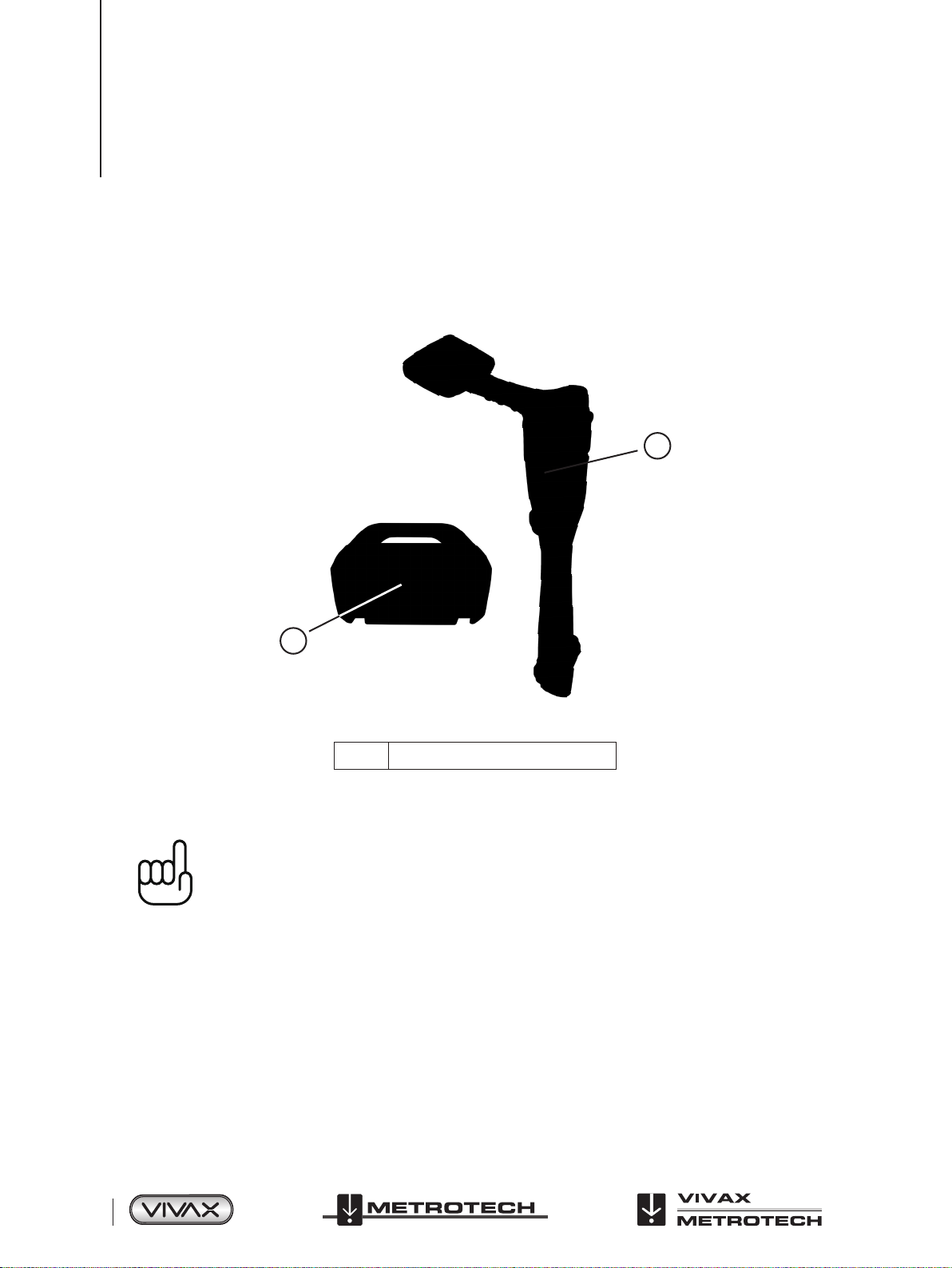
2.1 Serial Number and Software Revision Number
Always quote your receiver and transmitter model number, serial number and software revision number when requesting product
support. They can be found as follows: (for reference only).
1
1
1 Model & Serial Number
NOTE
The transmitter Model & Serial Number can be found at the bottom of the transmitter and inside the
transmitter between the battery tray and the main module of transmitter.
Software Revision Number: On both receiver and transmitter the software revision number is
displayed on the LCD during the startup sequence or can be found in the “About” section of the user
menu.
Page 4 of 75
™

2 Service & Support
2.2 Distributors and Service Centers Closest to You:
World Headquarters, United State of America Central/South America and the Caribbean
Vivax-Metrotech Corporation
3251 Olcott Street,
Santa Clara, CA 95054, USA
Website: www.vivax-metrotech.com
Sales & Sales Support:
T/Free : 800-446-3392
Tel : +1-408-734-1400
Fax : +1-408-734-1415
Email : sales@vxmt.com
Service & Repairs:
T/Free : 800-638-7682
Tel : +1-408-962-9990
Fax : +1-408-734-1799
Email : service@vxmt.com
Australasia
Vivax-Metrotech AUS
Unit 1, 176 South Creek Road,
Cromer NSW 2099, Australia
Ventas para América Latina
3251 Olcott Street,
Santa Clara, CA 95054, USA
T/Free : 800-624-6210
Tel : +1-408-734-1400
Fax : +1-408-743-5597
Website : www.vivax-metrotech.com
Email : VentasparaAmericaLatina@vxmt.com
China
Leidi Utility Supply (Shanghai) Ltd.
No. 780, Tianshan Rd,
Shanghai, China 200051
T/Free : 4008-206-719
Tel : +86-21-5235-3001
Fax : +86-21-5235-8365
Website : www.leidi.cn
Email : info@leidi.cn
Tel : +61-2-9972-9244
Fax : +61-2-9972-9433
Website : www.vivax-metrotechaus.com
Email : sales@vxmtaus.com
service@vxmtaus.com
Canada
Vivax Canada Inc.
41 Courtland Ave Unit 6,
Vaughan, ON L4K 3T3, Canada
Tel : +1-289-846-3010
Fax : +1-905-752-0214
Website : www.vivax-metrotech.com
Email : CanadianSales@vxmt.com
Germany
Metrotech Vertriebs GmbH
Am steinernen Kreuz 10a
D-96110 Schesslitz
Tel : +49 954 277 227 43
Email : serviceGermany@vxmt.com
France
Vivax-Metrotech SAS
Technoparc - 1 allée du Moulin Berger,
69130 Ecully, France
Tel : +33(0)4 72 53 03 03
Fax : +33(0)4 72 53 03 13
Website : www.vivax-metrotech.com
Email : salesfrance@vxmt.com
United Kingdom
Vivax-Metrotech Ltd.
Unit 18-19, Woodside Road,
South Marston Industrial Estate,
Swindon, SN3 4WA, UK
Free Phone: 0800 0281811
Tel : +44(0)1793 822679
Website : www.vivax-metrotech.com
Email : salesUK@vxmt.com
™
Page 5 of 75
3 vLoc3-5000 Receiver
1
2
3
4
5
6
7
8
3. vLoc3-5000 Receiver
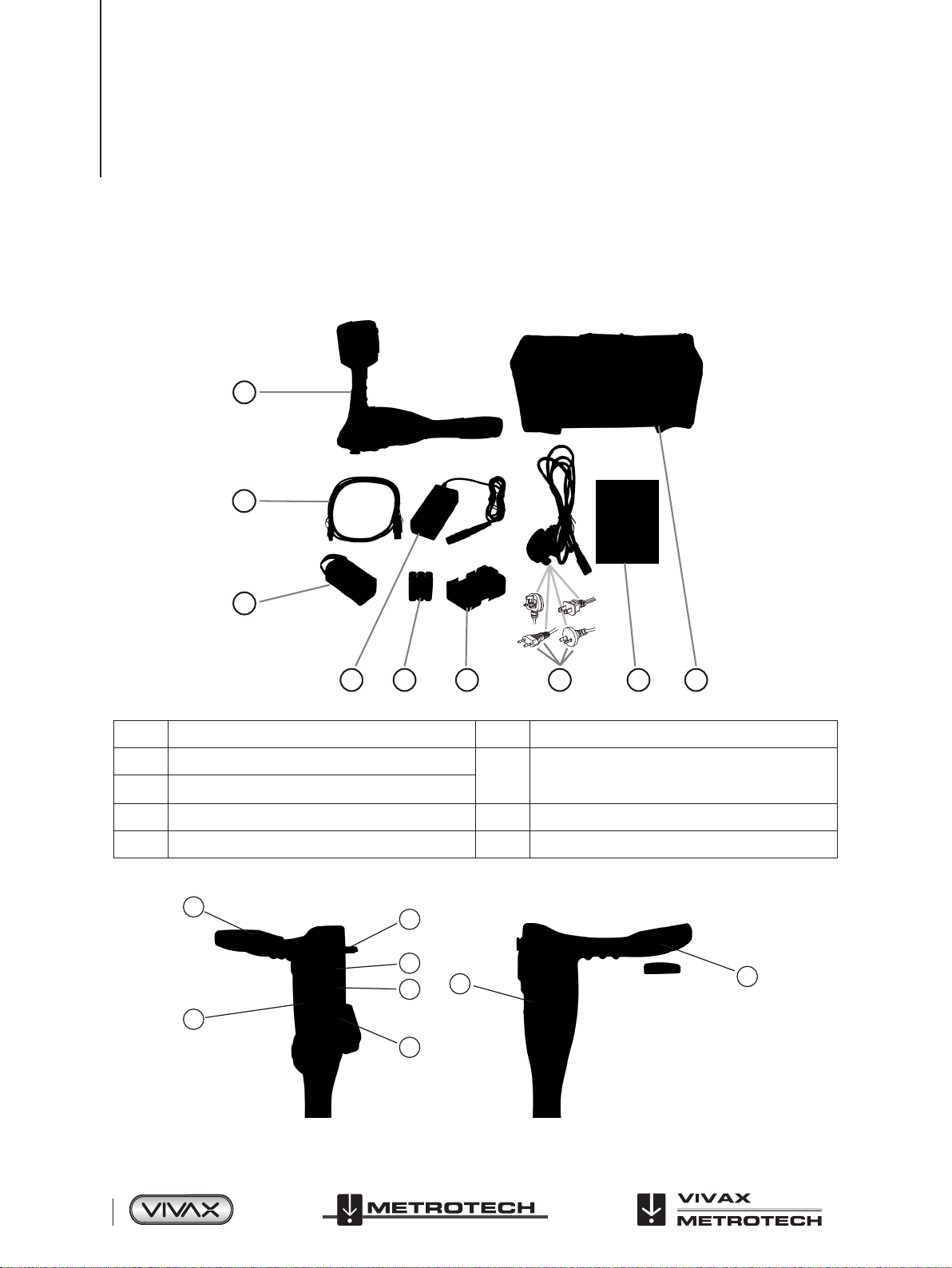
3.1 vLoc3-5000 Receiver Overview
The vLoc3-5000 is a Precision Location System designed to meet the needs of utility companies and their contractors. The
following describes the features and use of the receiver:
1
2
3
4
1 vLoc3-5000 receiver 6 Alkaline battery holder
2 Mini-USB cable
3 Li-ion battery
4 Charger 8 User manual
5 AA alkaline batteries 9 Soft kit carry bag
5
6 7 8 9
Power cable for charger
7
*one of supplied based on geographical location
Page 6 of 75
™
3 vLoc3-5000 Receiver
1 Pushbutton keypad display 5
2 Model# & Serial# 6 Battery compartment cover
3 Battery retaining cover 7 Accessory socket and charging point
4 AA alkaline battery pack/rechargeable battery pack 8
Mini-USB port for data transfer and software
updates
Expansion sockets for additional features such as
the Bluetooth module
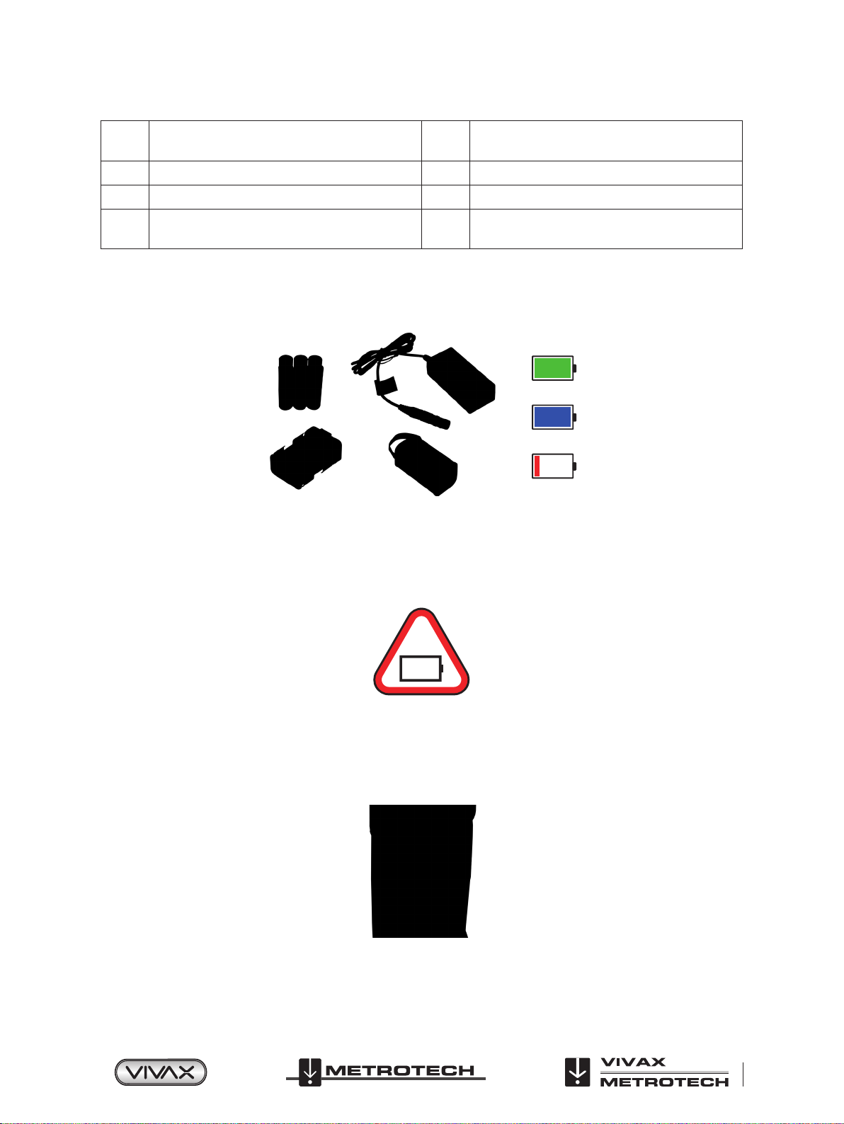
3.2 Charging the Receiver Batteries
The vLoc3-5000 can be used with either alkaline batteries or an interchangeable rechargeable battery pack.
The central illuminated section within the battery icon indicates the amount of charge remaining.
● Blue centre indicates Alkaline batteries.
● Green centre indicates rechargeable batteries.
● When batteries are low the charge remaining section becomes red and will flash
● Just before shutdown the following symbol will be shown:
.
Rechargeable batteries are supplied with a mains charger. This is specific to the batteries, avoid the use of other manufacturers’
chargers as these may damage the battery pack and may result in overheating of the battery pack.
To charge the rechargeable batteries, first make sure the pack is inserted in the receiver battery compartment as charging is
done with the battery inside the receiver.
Connect the charger to the charging/accessory socket of the receiver. Connect the charger to the mains and switch on. The LED
indicator on the charger will illuminate red until the batteries are fully charged at which time the LED will change to green.
™
Page 7 of 75
3 vLoc3-5000 Receiver
WARNING
Rechargeable batteries are supplied with a mains or 12V DC charger. These are specific to the
batteries. Only use the charger that is appropriate for the batteries in the product. If in doubt, call
the Vivax-Metrotech customer service department at +1(800) 446-3392. Failure to use the appropriate
charger could result in damage to the battery pack, locator and in extreme cases cause fire.
Avoid charging the unit in extreme temperature conditions. (i.e. below 0ºC and above 45ºC)
Although Vivax-Metrotech batteries include all the required safety related features, immediately
discontinue use of the charger and battery pack if the battery pack becomes excessively warm.
Return both to where they were purchased for investigation.
Always ensure batteries have at least a partial charge if storing for long periods without use.
Dispose of all batteries in accordance with your company procedures and Federal/State and local
regulations.
Never dismantle batteries, put them in fire, or get wet.
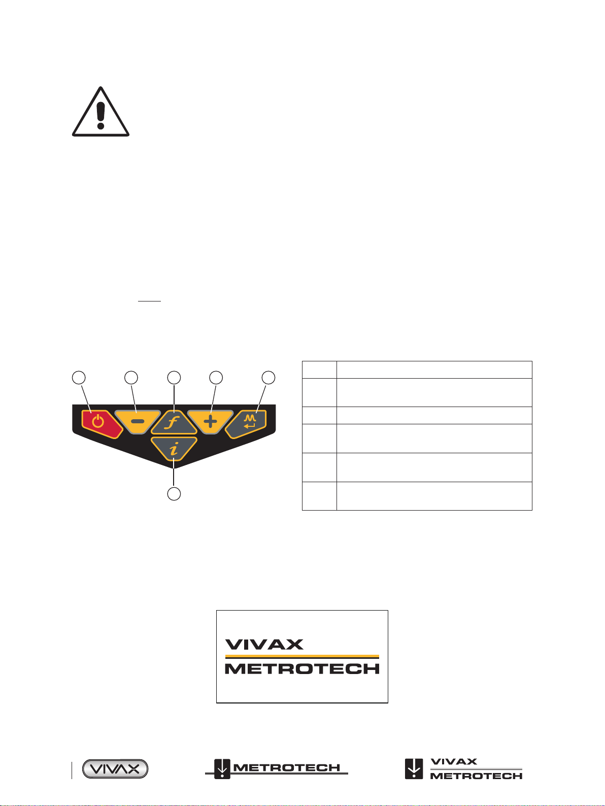
3.3 vLoc3-5000 Receiver Keypad
Keypad:
1 2 543
1 On/Off
Reduce sensitivity
2
(Also scroll up when in User Menu)
3 Select frequency
Increase sensitivity
4
(Also scroll down when in User Menu)
Short press = change antenna response
5
Long press = change operational screen
6
Short press = enter information screen
6
Long press = enter User Set-up options
3.4 User Menu
The vLoc3-5000 has several features that can be switched on and off. These features are accessed through the user menu.
Switch on the unit by pressing and holding the On/Off key until the start-up screen appears. The start-up screen can be
configured to the user’s preference and is described later in the manual. Otherwise the start-up screen will default to the one
below:
Page 8 of 75
™

3 vLoc3-5000 Receiver
Access to the User Menu is via the “ i ” button. Press and hold down the button until the menu appears.
Menu
About
Speaker Volume
Sound Configuration
Backlight
Frequency
Classic Locate
Locate Perspective
Auto
Menu
Self Test
Note that the manual shows three screens but only one is shown on the vLoc3-5000 display at a time.
Note that where you see this sign
it means that pressing the enter button gives access to the sub-menu associated with this
button.
To exit the menu or sub-menu, press the “ i ” button.
Language
Imperial / Metric
Continuous Information
Auto Power Off
Warnings
GPS Source
Bluetooth Pairing
Main Menu
Menu
English
Feet
Depth & current
10 Minutes
Internal
Where the
icon is not shown, the enter button is used to scroll through the options of that feature.
Use the “+” and “ - ” buttons to scroll up and down through the menu.
The features are described below:
3.4.1 About
This section holds the data about the locator such as software revision, calibration data etc.
3.4.2 Speaker Volume
Press the enter button to scroll through the speaker volume settings.
3.4.3 Sound Configuration
Allows configuration of sounds generated in locate modes.
● Active mode:
ο Frequency Modulated (FM) Sound pitch changes with signal strength.
ο Amplitude Modulated (AM) Sound volume changes with signal strength.
● Radio mode: FM or Real (Sound derived directly from received signal).
● Power mode: FM or Real.
3.4.4 Backlight
Press the enter button to change the backlight intensity setting. Note that high backlight setting will affect battery life. Or select
“Auto” which automatically sets backlight depending on ambient light levels.
™
Page 9 of 75
3 vLoc3-5000 Receiver
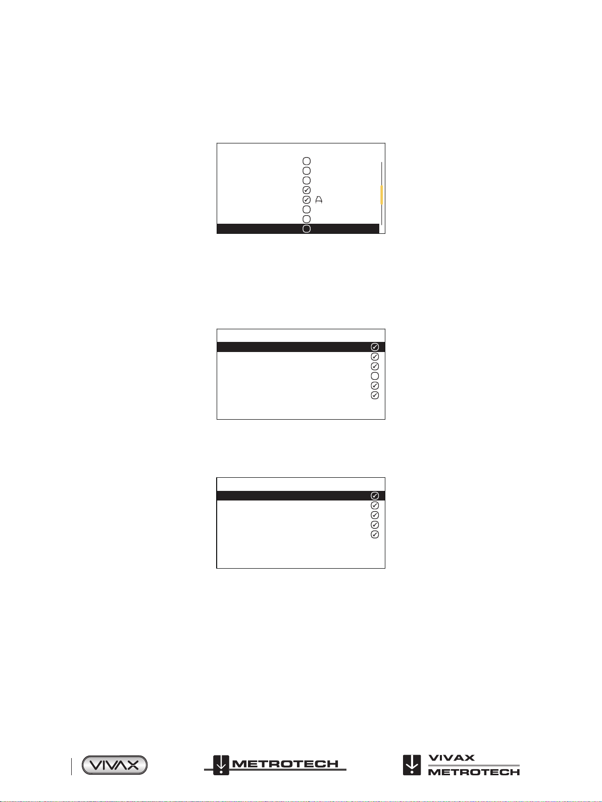
3.4.5 Frequency
Use the enter key to enter the Frequency Sub-Menu. Scroll up and down the table using the “+” and “-” keys. The table contains
all available frequency options. To simplify the operation of the unit, select only the frequencies applicable you your application.
To do this use the enter key to check the boxes on the right. Frequencies not checked will not appear of the locate screen.
Frequency
1.45kHz
2.0kHz
8.01kHz
8.19kHz
8KFF
8.44kHz
9.5kHz
9.8kHz
Note also that certain frequency options have an A-frame icon next to them. This indicates that these frequencies are selected to
be used with the fault find A-frame.
3.4.6 Classic Locate
This option is only shown if the User Menu is entered from the Classic Screen.
Use the enter key to reveal the list of options relating to the Classic Locate modes. Options are:
Classic Locate
Peak
Null
Broad
Delta Null
Omni Directional Peak
Omni Directional Peak
3.4.7 Locate Perspective
Enter this option to be able to select in what graphical format the data is displayed. These displays are described further in the
manual. The options are:
Locate Perspective
Classic Locate
Vector locate
Transverse graph
Plan view
Sonde
3.4.8 Language
The unit may be supplied with different language options. Use the enter key to select the language of choice.
3.4.9 Imperial/Metric
Select either Imperial or Metric measurements
.
3.4.10 Continuous Information
The front Locate Screen can display a continuous reading of either Depth, Current, Both or can be switched off. Use the enter
button to select your preference.
Page 10 of 75
™
3 vLoc3-5000 Receiver
3.4.11 Auto-Power Off
The unit can be set to switch off after a set time. Options are: 5mins, 10mins, Never. Note that when the A-frame is connected
the timer is set to “Never”.
3.4.12 Warnings
Warnings relating to: Shallow cable, Overload, Overhead cable and Signal Overload. Scroll down to the relevant warning and
use the return button to select or de-select.
3.4.13 GPS Source (Internal GPS is a factory fit option)
Use the Enter key to select either “Internal” or “Bluetooth”, Bluetooth means connection to an external Bluetooth enabled GPS.
3.4.14 Bluetooth Pairing (Optional Feature)
Press the enter button to enter the Bluetooth pairing routine. This allows the unit to link with external devices such as
dataloggers and GPS devices that have Bluetooth capability.
3.4.15 Self-Test
Pressing the enter key will initiate a series of self-tests. If any of the tests fail repeat the test in a more interference free site
I.e. away from fluorescent lights, power signal sources etc. If the unit continues to fail, the unit should be returned to VivaxMetrotech Corporation or one of its authorised service centers for repair.
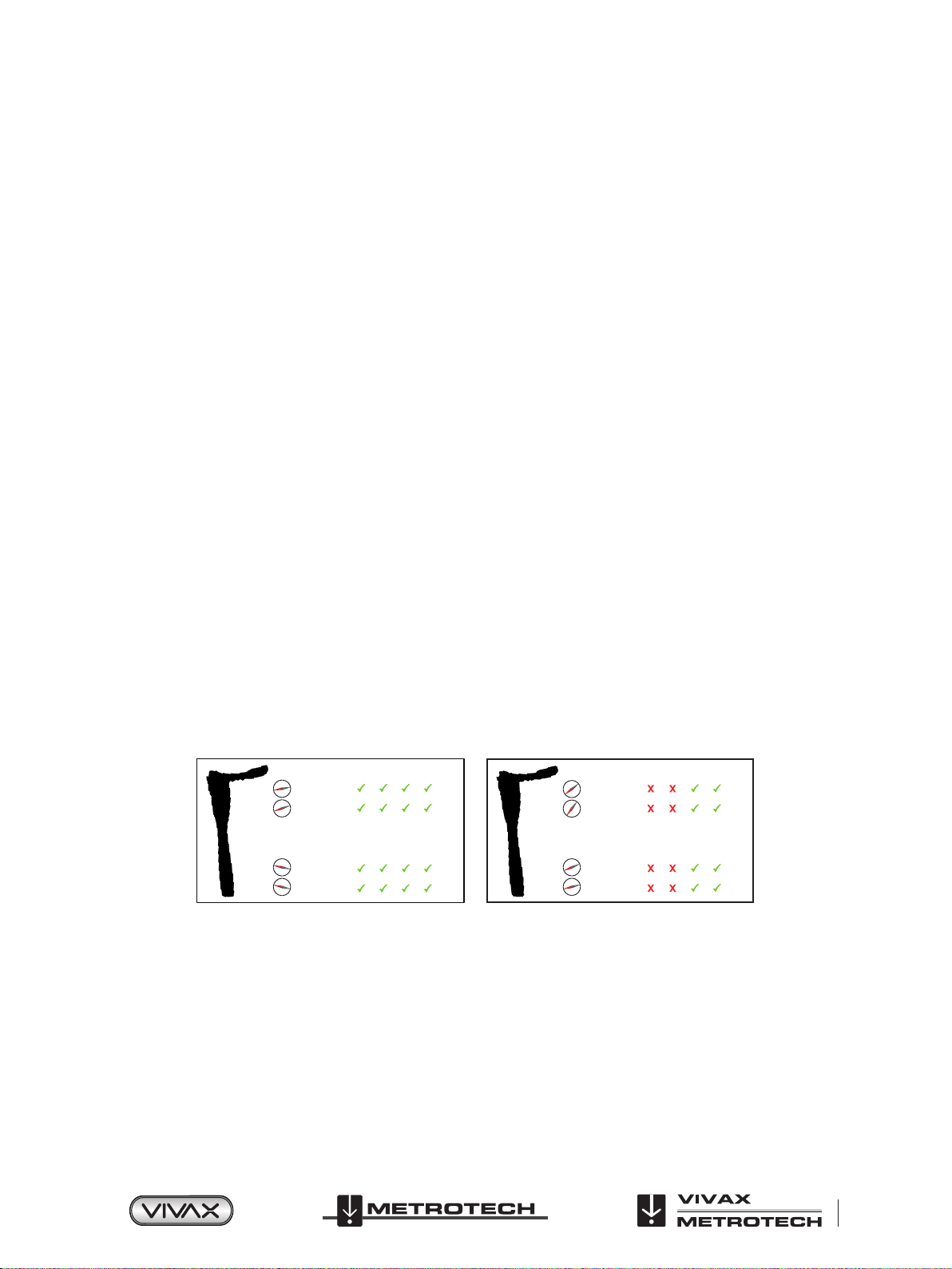
3.5 Self-Test
The vLoc3-5000 has a Self-Test feature. The test confirms that the equipment is fit for use and calibration has not drifted from its
expected settings.
To undertake the test, first find an area free from excessive interference such as overhead fluorescent lighting, large
transformers etc. Also check that any nearby vLoc transmitters are switched off.
Select “Self-Test” from the user menu and press the “Return” button. The test will self-start. Keep the equipment stationary while
the test is completed. After a short while the unit will report a Pass or Fail. Examples are below:
Self Test: PASSED
108.1
63.1
88.6
87.0
If the unit fails the test, try again in a more interference free area. If it continues to fail, return the unit to Vivax-Metrotech or one
of its approved repair centers for investigation and repair.
Self Test: FAILED
108.1
63.1
88.6
87.0
™
Page 11 of 75
3 vLoc3-5000 Receiver
94.6
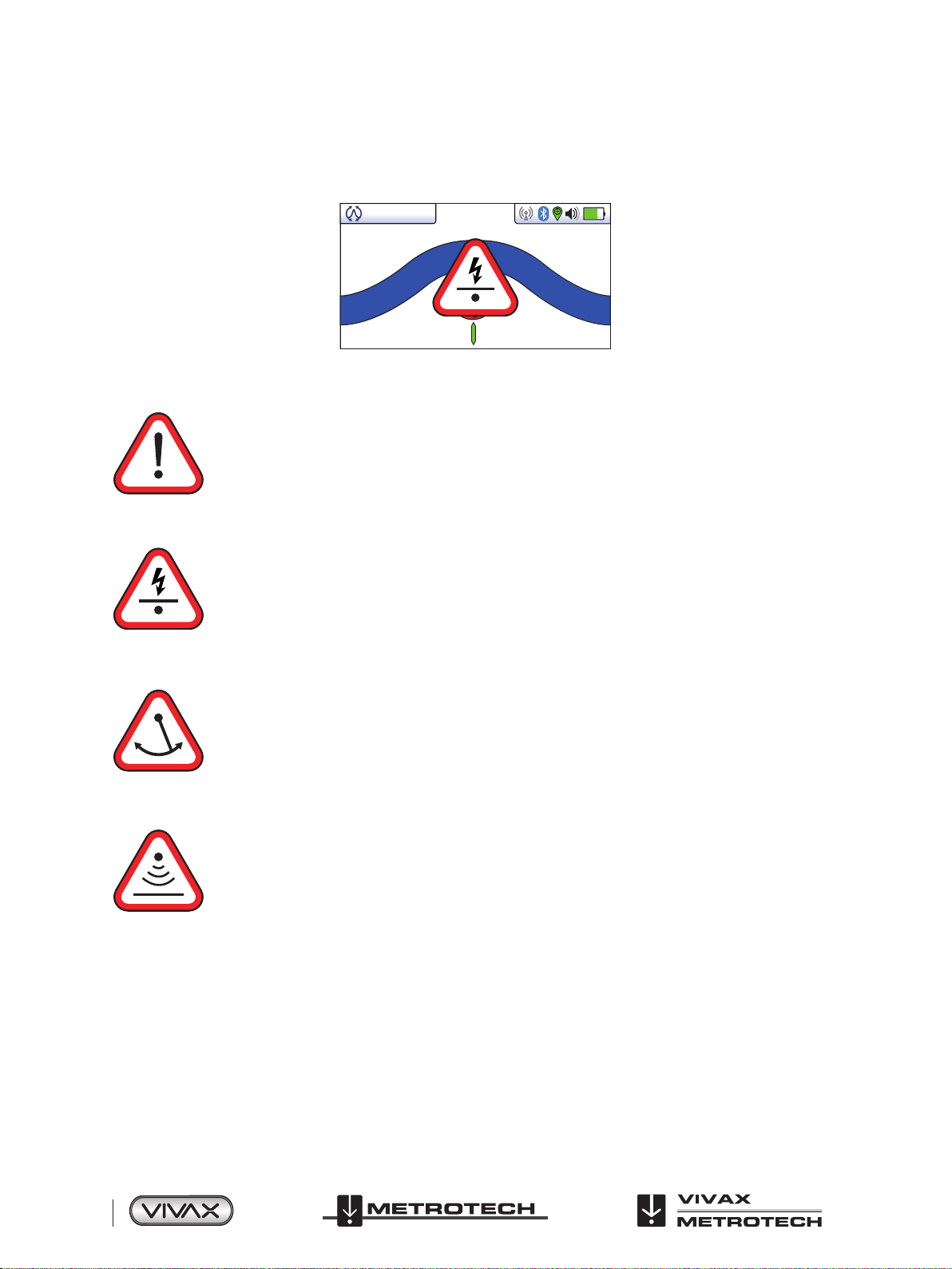
3.6 Warnings
Warnings are displayed in real time across the display as below:
3.6.1 Signal Overload
This a very unusual situation and is usually caused by operating VERY close to a power transformer or
placing the unit very close to a transmitter in the Induction mode. Moving slightly away from the interfering
signal will cure the problem. Signal overload will not cause damage to the instrument.
3.6.2 Shallow Cable
Power 5043dB 0.00mA
This indicates that the locator has detected a cable that is possibly less than 15cm deep. Proceed with
caution.
3.6.3 Swing Alert
This indicates that the operator is swinging the locator excessively and could result in misleading information.
When sweeping the locator across the direction of the line, try to keep it vertical. This will improve accuracy.
3.6.4 Overhead cable
This indicates that the signal is mainly radiating from above. This is usually caused by the signal travelling
along overhead cables.
The warning symbols are accompanied by an audible sound and a vibration in the handle unless configured otherwise (see
MyLocator3). Warnings can also be switched off in the User Set-up menu.
Page 12 of 75
™

3 vLoc3-5000 Receiver
60.0
0.39m
3.7 vLoc3-5000 Receiver Locate Screen Shots
The user interface of the vLoc3-5000 is under continual development. The screen shots described may differ slightly from
current screens.
The vLoc3-5000 gives the user a choice of different locate screens. The choice of screen depends on application and user
preference.
● Classic Screen
● Vector Screen
● Plan view Screen
● Transverse Plot Screen
This manual will first explain the functions of the “Classic Screen” as familiarity of this screen will help understand the functions
of the others.
An overview of the Classic Screen
Classic Screen
4’0”
SIS-491kHz24dB 68mA
Status bar:
All the screens have a status bar at the top which indicates various settings of the locator. The bar is shown below:
3 875 64
21
1 Antenna configuration (meter response) described later in the manual
2 Depth to target line, can also be set to display signal current on line or both
3 Radio link to transmitter status
4 Bluetooth status
5 GPS status
6 Speaker volume setting
7 Battery type and remaining charge
™
Page 13 of 75
3 vLoc3-5000 Receiver
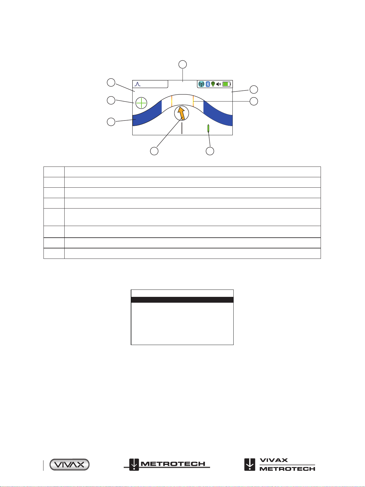
The Classic Screen has all the functions normally seen on a classic cable locator. The main functions being:
1
2
3
4’0”
60.0
SIS-491kHz24dB 68mA
8
7
4
5 6
1 Percentage signal strength (mirrors the bar graph setting)
2 Gain setting
3 Only visible with SiS frequencies, “+” indicates correct line, “ - ” indicates incorrect line
4 Bar graph signal strength indicator
Compass line direction indicator (when using an SiS frequency, arrow points forward on correct line, it will reverse
5
on incorrect line)
6 Line position indicator
7 Red section indicates level of field distortion. This will be empty where distortion is minimal
8 Peak level indicator, red bar and green section shows difference between peak signal and actual signal
Tip:
When in a locate screen, pressing and holding the “ f ” key will bring up the frequency table.
Radio
SD-EUR
8kHz
8KFF
33kHz
83kHz
200kHz
Use the “+” and “ - ” keys to navigate quickly to the desired frequency. Press the “ i ” key to select a highlighted choice and return
to the locate screen.
Page 14 of 75
™
3 vLoc3-5000 Receiver
Screen Icons explained
Classic Screen/Antenna configurations:
Icon Description Function/response
Peak
Null
Broad peak
Dual horizontal antennas giving largest signal over the line with sharp accurate results.
Less affected by distorted signals.
Vertical antenna giving minimum signal over the line with sharp response but more affected
by distorted signals. Can be used to identify distorted signals by comparing results with the
peak mode.
Uses single antenna. Not so accurate as dual peak antennas and more difficult to pinpoint
the line but gives a signal boost from deep lines.
Delta-Null
Omni direction
Uses dual null antennas to minimise the offset effects of field distortion. This mode tends to
be more precise than the Null mode.
When you see the two double ended arrows around an icon, this means that the line is
detectable regardless of locator blade orientation. It is very useful for quickly checking an
area for buried lines.
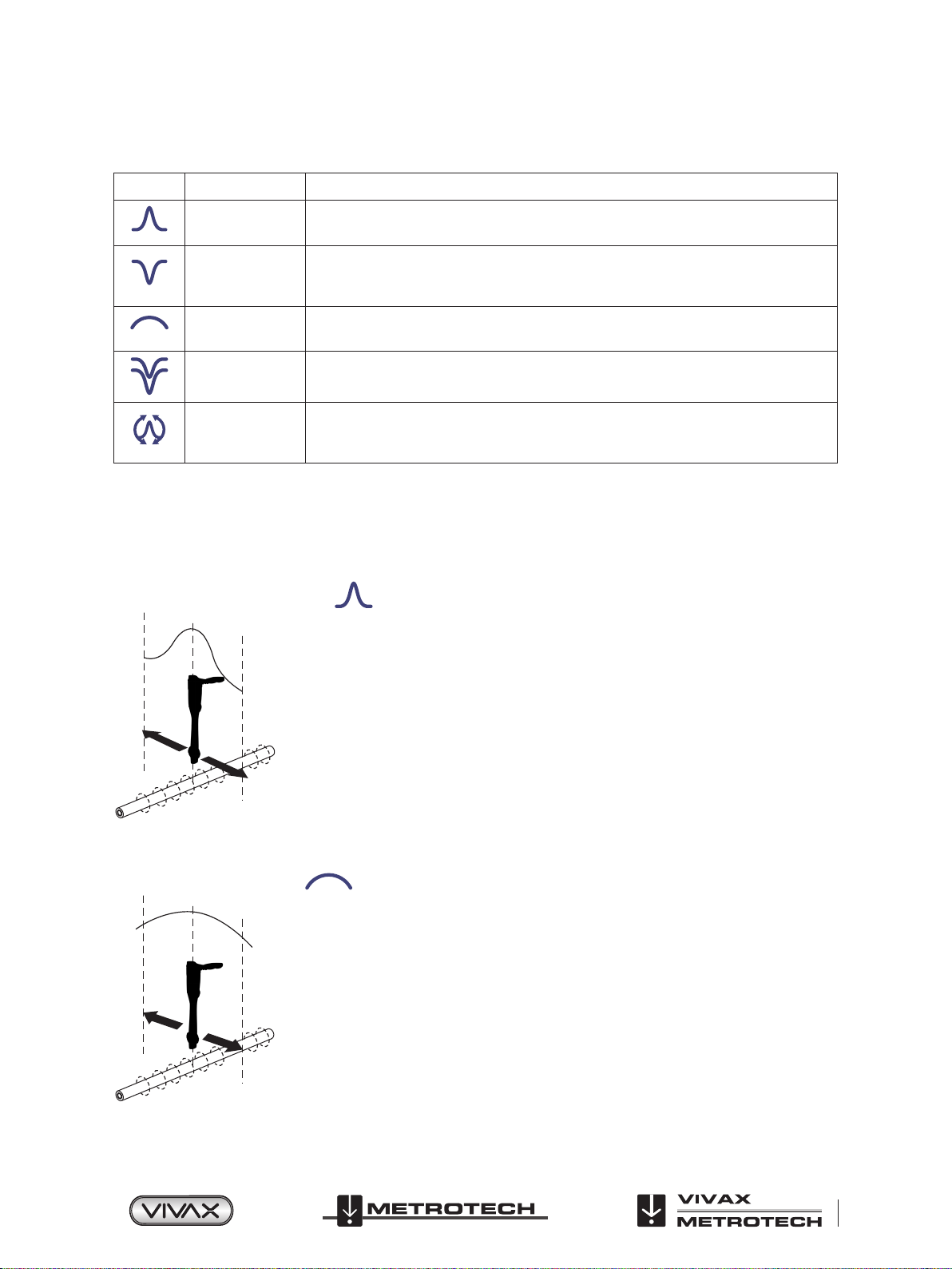
3.8 Classic Locating Modes (Response)
The vLoc3-5000 receiver has an array of six antennas, and these can be toggled through different configurations (modes) to
provide different responses to the signals radiating from buried utilities. The modes are:
3.8.1 Peak Response Mode
Two horizontal antennas provide a “Peak” or maximum signal response over the center of the
buried line. The compass (line direction indicator) aligns itself parallel to the direction of the
cable together with a line position indicator showing which side of the line the locator is (available
in Active modes).
This is an accurate method of the locating as both horizontal antennas are used to provide a
clearly identifiable “Peak”. It is also less prone to the effects of signal distortion.
A Peak Level Indicator is also provided on the bar graph. This indicates the largest signal
detected allowing the user to quickly return to this point.
3.8.2 Broad-Peak Mode
This uses a single horizontal antenna and provides a “Peak” or maximum signal response over
the center of the buried line. The compass (line direction indicator) aligns itself parallel to the
direction of the cable together with a line position indicator showing which side of the line the
locator is (available in Active modes).
This gives a less defined peak than the twin horizontal antenna “Peak” mode – but is useful in
some situations such as deep lines because using a single antenna has the effect of boosting
the received signal.
™
Page 15 of 75
3 vLoc3-5000 Receiver
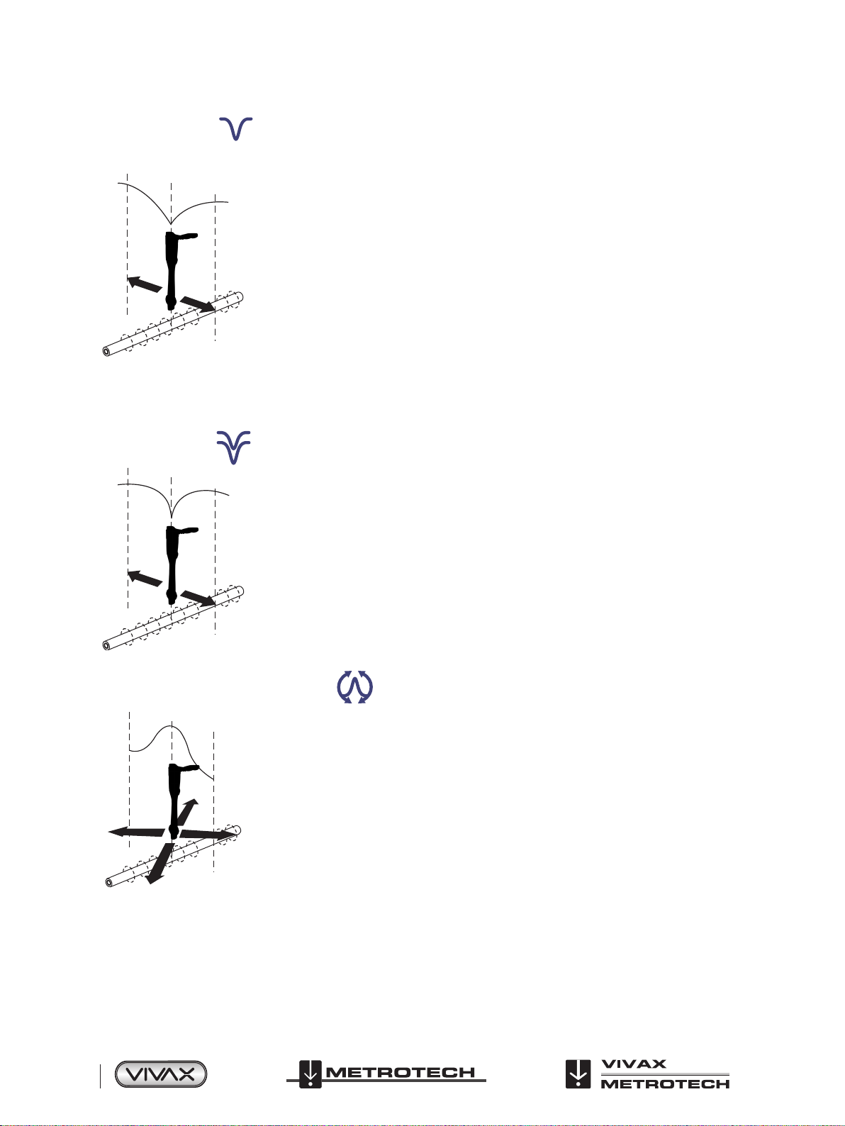
3.8.3 Null Mode
3.8.4 Delta Null
This uses vertical antennas, and provides a minimum or “Null” response over the center of the
buried line.
The compass (line direction indicator) aligns itself parallel to the direction of the cable together
with a line position indicator showing which side of the line the locator is (available in Active
modes).
The null mode works well in uncongested areas but is more prone to inaccuracies due to the
effects of field distortion. This effect can be utilised to detect the presence of distorted fields.
Compare the locate position “Null Mode” with the position “Peak Mode”. If the two positions
do not coincide, this indicates possible distortion. The greater the difference the greater the
distortion.
Left/right indication arrows are also displayed when in “Null” mode. The arrows indicate the
direction to move the receiver to locate the position of the buried line.
This uses dual vertical antennas. This has the advantage that it provides a sharper response
than the “null” mode and is less affected by distorted fields. All other functions are the same as
the “Null” mode.
3.8.5 Omni-Peak Response Mode
When you see the two double ended arrows around an icon, this means that the line is
detectable regardless of locator blade orientation. It is very useful for quickly checking an area
for buried lines using a grid search as one sweep will catch all locatable lines. In the classic
screen the Omni feature is available in the “Peak” and “Broad Peak” modes.
The compass and line position indicators are also shown when the double arrow icon is shown.
Page 16 of 75
™
3 vLoc3-5000 Receiver
3.9 Information Pushbutton (Depth & Current)
50°42′59.90570′′N
3°26′35.54358′′W
27.50m
Pushbutton
0.54m 163mA
Log 2
SD
0
When in a Locate screen, a quick press of the “ i ” (information) pushbutton will display the depth and signal current.
The display shown above shows Longitude/Latitude positional information. To the top right is the hight above sea level. This is
only displayed when the equipment is paired with a valid GPS system and a valid signal is received.
It is also possible to save the data to the internal memory. This is explained in detail in the “Datalogging” section.
IMPORTANT
When locating a cable or pipe (“line”) – depth and current measurements should only be taken with
the bottom of the receiver standing on the ground and directly in line with the target line. Unless the
Omni-direction mode is selected in which case orientation is not important.
The accuracy of depth and current readings depends on the quality of the radiated signal being located. If the signal is
undistorted, the depth reading will be accurate to within 3%. The accuracy also depends on the care taken in pinpointing the
line. A more accurate pinpoint, results in better depth and current measurements.
The SiS icon indicates which button to press to temporally reset the SiS signal reference. This is not normally necessary but is
explained in the SiS/SD section.
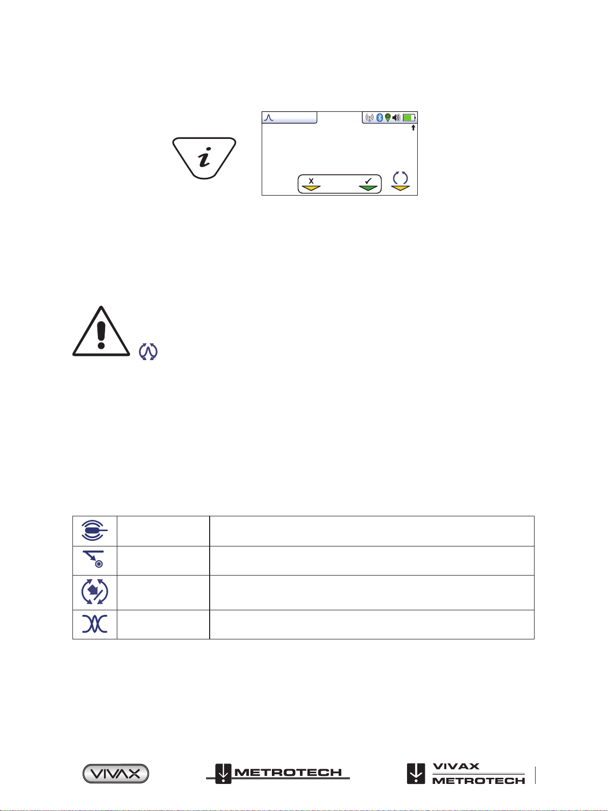
Alternative locate screens
As previously mentioned, the vLoc3-5000 has a number of alternative screens. The following section describes operation these
screens. It is left to the user to decide which is the best screen for a particular application.
To scroll through the available screens, use long key presses on the “return” key.
Sonde Specific mode for detecting and locating sonde transmitters.
Vector configuration Shows a cross section of the ground and line position relative to the locator.
Plan view Gives a plan view as if looking into the ground.
Transverse graph
Shows a graphical representation of the peak and null field shape over a line (Active
modes only) good for analysing signal distortion.
™
Page 17 of 75
3 vLoc3-5000 Receiver
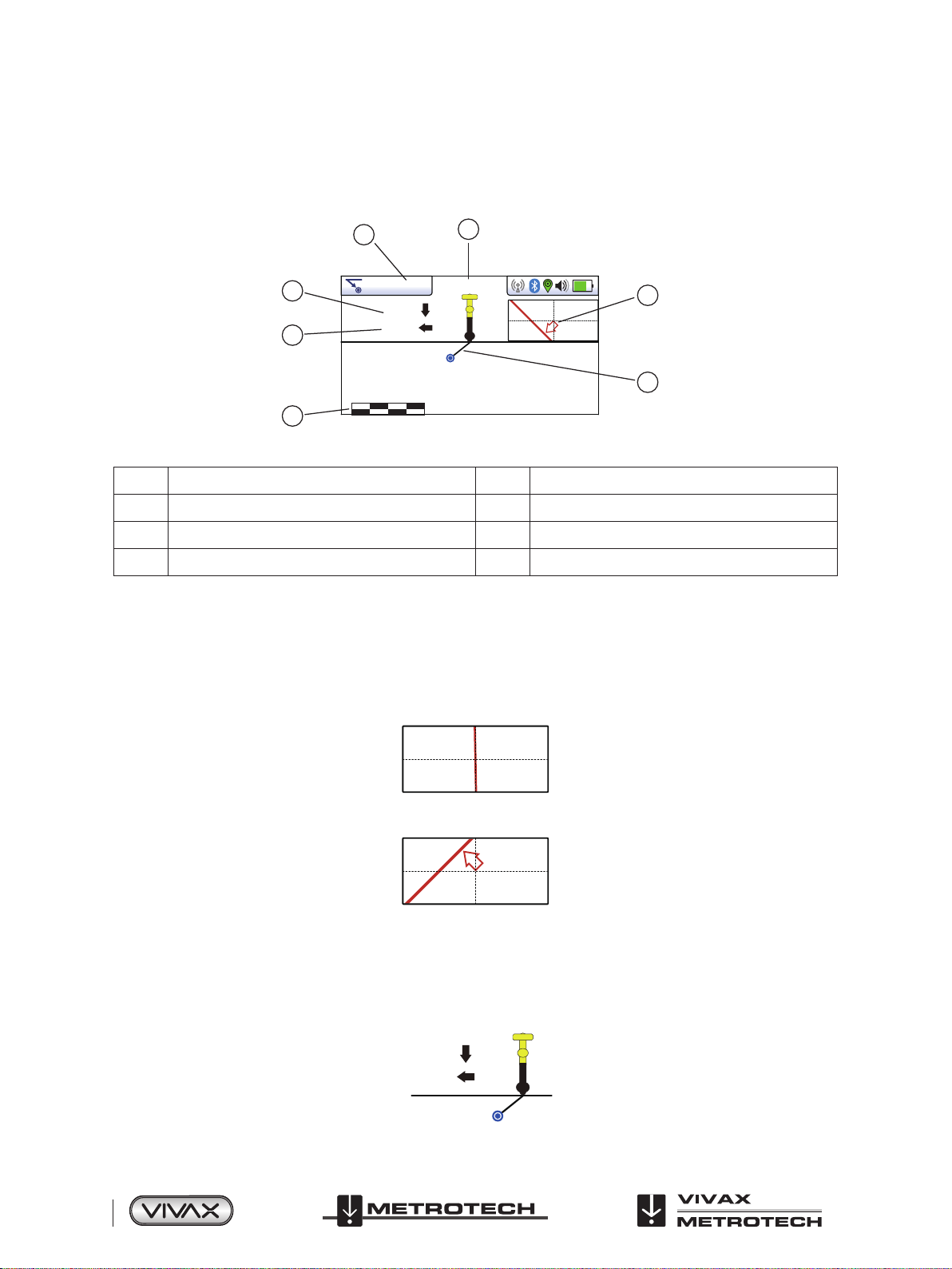
Vector Screen
The Vector Screen shows a cross sectional view through the ground. A plan view is also shown to help orientate the user
over the line. The Vector Screen is particularly useful where access directly over the line is not possible. Depth and horizontal
displacement distances are shown, even when not directly over the line.
2
3
4
85.6mA
1.43m
1.86m
0 2m
1
8.19kHz
6
7
5
1 Frequency selected 5 Scaling (adjust with +/- keys)
2 Signal current 6 Shows plan view of target
3 Vertical distance to target 7 Cross section view that shows vectors to target
4 Horizontal distance to target
Using the Vector screen
1. Apply the signal to the target line in the usual way and select the vector screen by using long presses on the “return” button
until the desired screen appears.
2. Position the locator within the approximate position of the target line. Use the plan view to help guide you towards the target
line. You can imagine that the plan view is giving you a view into the ground.
3. Position yourself so that the red target line is pointing forward/back and is centralized on the screen.
Page 18 of 75
4. If the target is off the screen an arrow will appear on the screen to help direct you to the target line.
5. The cross-sectional section of the screen will respond as the target is approached. Use the “+” and “–” keys to alter the
scaling if necessary.
6. There is a black line leading from the locator to the target line. The target is represented by a blue dot. Around the dot is
a circle, the size of the circle indicates a confidence factor. The larger the circle the less confident the indicated position.
Generally, the actual position of the line will be within the confidence circle.
1.43m
1.86m
™
3 vLoc3-5000 Receiver
The color of the confidence circle also changes depending on the degree of confidence:
Green: - Low distortion/high confidence.
Blue: - Minor distortion/medium confidence, proceed with care.
Red: - Excessive distortion/low confidence, treat all data and measurements with caution.
7. Notice that vertical and horizontal distances from the target line are displayed.
1.43m
1.86m
This must not be mistaken for the distance diagonally to the target, this information is not displayed. The vertical distance is the
true depth from the bottom of the locator. The advantage of this is that the depth and position of the target can be determined
without being directly over the target line. So, in the event of an obstruction at the measuring point, data can still be gathered by
placing the locator to one side of the target.
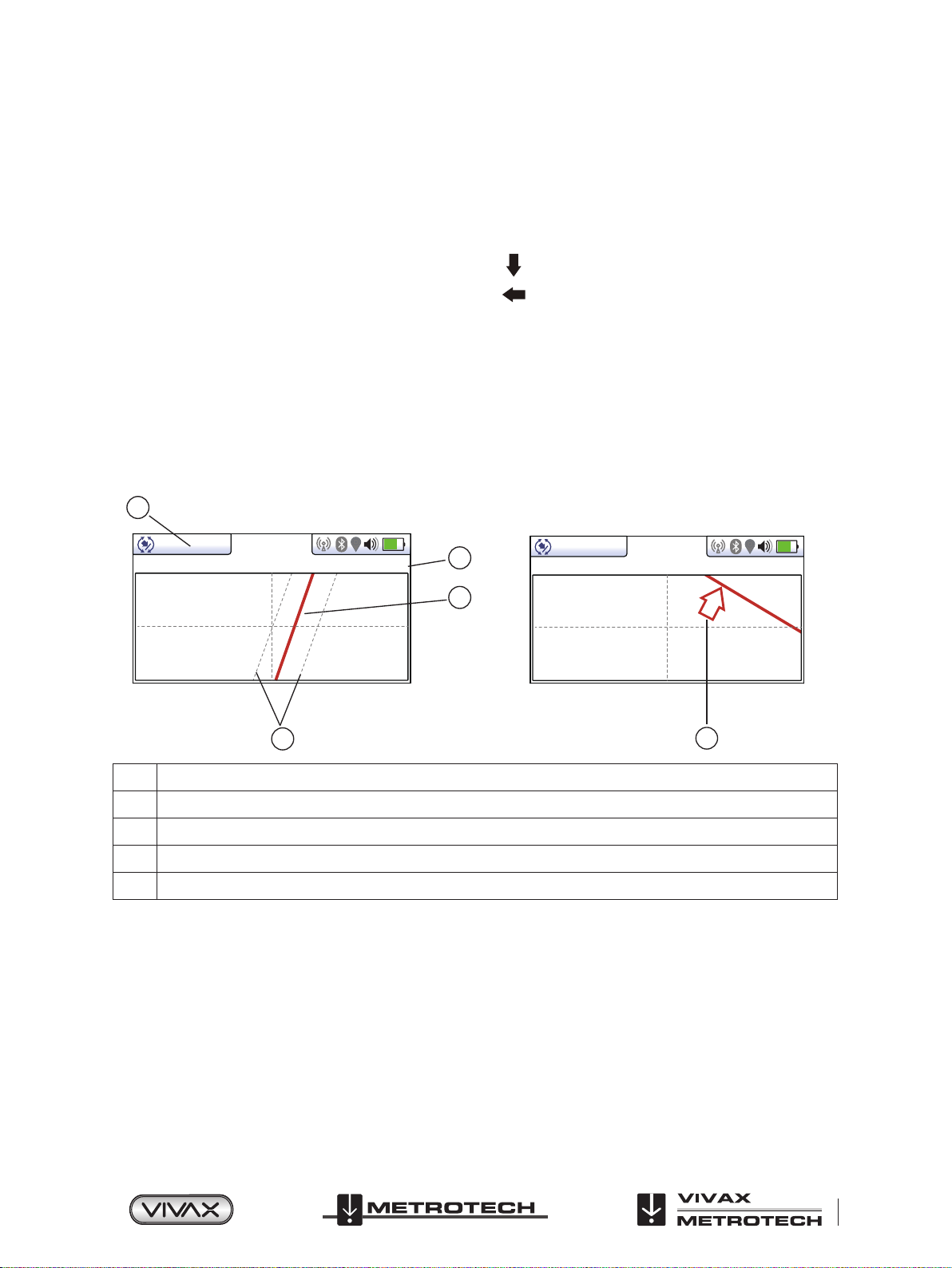
Plan View Screen
The Plan-View Screen shows a picture as if you were viewing the line from above ground. When the line is in the center and
pointing forward/back then you are directly over the line and pointing in the direction of the line.
1
14’5’’
12.9mA 32.8kHz
2
14’5’’
12.9mA 32.8kHz
3
4
1 Depth and current readings
2 Frequency selected
3 Target line
4 Lines of confidence (closer these are to the target line indicates more confidence)
5 Arrow indicates direction to move towards line. It only shows when the distance to the target line is far away.
Using the Plan-View screen
1. Apply the signal to the target line in the usual way and select the Plan-View screen by using long presses on the return
button until the desired screen appears.
2. Position the locator within the approximate position of the target line. Use the plan view to help guide you towards the target
line. You can imagine that the plan view is giving you a view into the ground.
5
™
Page 19 of 75
3 vLoc3-5000 Receiver
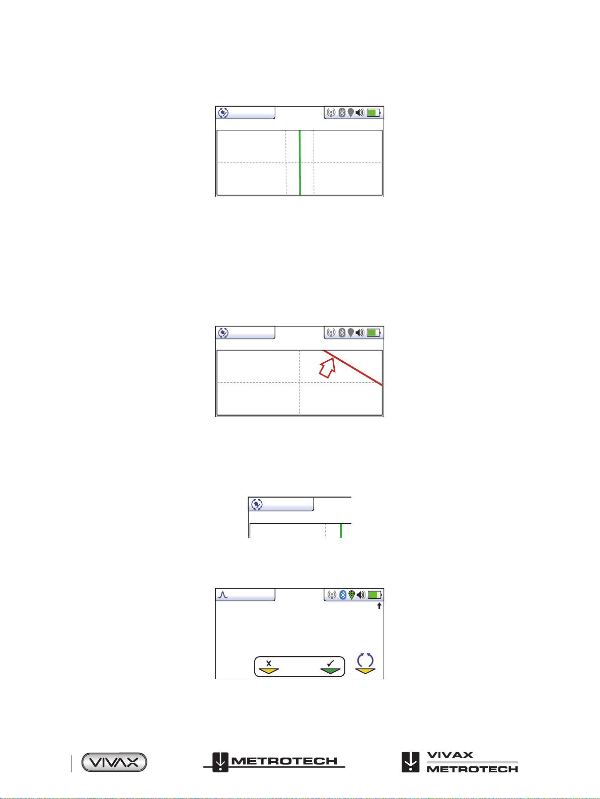
0.18m
32.8kHz
3. Position yourself so that the target line is pointing forward/back and is centralized on the screen.
0.18m
3.59mA 32.8kHz
“Tram” lines either side of the line indicate an area of confidence. The closer the tram lines are together the greater the
confidence.
In addition to the tram lines, the color of the target line also changes depending on the degree of confidence:
Green: - Low distortion/high confidence.
Blue: - Minor distortion/medium confidence, proceed with care.
Red: - Excessive distortion/low confidence, treat all data and measurements with caution.
4. If the target is off the screen an arrow will appear on the screen to help direct you to the target line.
14’5’’
12.9mA 32.8kHz
5. As long as the locator is detecting a valid signal, the depth (or current) will be available regardless of locator orientation i.e.
the locator does not need to be aligned with the target line in the forward back orientation. It is recommended that, in this
mode, the current is always displayed as it is possible signal will bleed off onto other services. Regular checks on the signal
current i.e. checking for large changes, will ensure the correct line is detected.
3.59mA
6. A short press on the info button will display the Information Screen. More information relating to the Information Screen is
described in a previous section “Information Pushbutton (Depth & Current)”.
50°42′59.90570′′N
3°26′35.54358′′W
27.50m
0.54m 163mA
0
Log 2
SD
Page 20 of 75
™
 Loading...